WO2019082902A1 - Dispositif de distribution, appareil de distribution et procédé l'utilisant, et appareil et procédé d'inspection - Google Patents
Dispositif de distribution, appareil de distribution et procédé l'utilisant, et appareil et procédé d'inspectionInfo
- Publication number
- WO2019082902A1 WO2019082902A1 PCT/JP2018/039382 JP2018039382W WO2019082902A1 WO 2019082902 A1 WO2019082902 A1 WO 2019082902A1 JP 2018039382 W JP2018039382 W JP 2018039382W WO 2019082902 A1 WO2019082902 A1 WO 2019082902A1
- Authority
- WO
- WIPO (PCT)
- Prior art keywords
- fluid sample
- dispensing
- accommodation
- inspection
- dispensing device
- Prior art date
- Legal status (The legal status is an assumption and is not a legal conclusion. Google has not performed a legal analysis and makes no representation as to the accuracy of the status listed.)
- Ceased
Links
Images


























Classifications
-
- G—PHYSICS
- G01—MEASURING; TESTING
- G01N—INVESTIGATING OR ANALYSING MATERIALS BY DETERMINING THEIR CHEMICAL OR PHYSICAL PROPERTIES
- G01N35/00—Automatic analysis not limited to methods or materials provided for in any single one of groups G01N1/00 - G01N33/00; Handling materials therefor
- G01N35/08—Automatic analysis not limited to methods or materials provided for in any single one of groups G01N1/00 - G01N33/00; Handling materials therefor using a stream of discrete samples flowing along a tube system, e.g. flow injection analysis
-
- B—PERFORMING OPERATIONS; TRANSPORTING
- B01—PHYSICAL OR CHEMICAL PROCESSES OR APPARATUS IN GENERAL
- B01L—CHEMICAL OR PHYSICAL LABORATORY APPARATUS FOR GENERAL USE
- B01L3/00—Containers or dishes for laboratory use, e.g. laboratory glassware; Droppers
- B01L3/50—Containers for the purpose of retaining a material to be analysed, e.g. test tubes
- B01L3/502—Containers for the purpose of retaining a material to be analysed, e.g. test tubes with fluid transport, e.g. in multi-compartment structures
- B01L3/5027—Containers for the purpose of retaining a material to be analysed, e.g. test tubes with fluid transport, e.g. in multi-compartment structures by integrated microfluidic structures, i.e. dimensions of channels and chambers are such that surface tension forces are important, e.g. lab-on-a-chip
- B01L3/502738—Containers for the purpose of retaining a material to be analysed, e.g. test tubes with fluid transport, e.g. in multi-compartment structures by integrated microfluidic structures, i.e. dimensions of channels and chambers are such that surface tension forces are important, e.g. lab-on-a-chip characterised by integrated valves
-
- G—PHYSICS
- G01—MEASURING; TESTING
- G01N—INVESTIGATING OR ANALYSING MATERIALS BY DETERMINING THEIR CHEMICAL OR PHYSICAL PROPERTIES
- G01N35/00—Automatic analysis not limited to methods or materials provided for in any single one of groups G01N1/00 - G01N33/00; Handling materials therefor
- G01N35/10—Devices for transferring samples or any liquids to, in, or from, the analysis apparatus, e.g. suction devices, injection devices
-
- G—PHYSICS
- G01—MEASURING; TESTING
- G01N—INVESTIGATING OR ANALYSING MATERIALS BY DETERMINING THEIR CHEMICAL OR PHYSICAL PROPERTIES
- G01N37/00—Details not covered by any other group of this subclass
-
- B—PERFORMING OPERATIONS; TRANSPORTING
- B01—PHYSICAL OR CHEMICAL PROCESSES OR APPARATUS IN GENERAL
- B01L—CHEMICAL OR PHYSICAL LABORATORY APPARATUS FOR GENERAL USE
- B01L2200/00—Solutions for specific problems relating to chemical or physical laboratory apparatus
- B01L2200/06—Fluid handling related problems
- B01L2200/0684—Venting, avoiding backpressure, avoid gas bubbles
-
- B—PERFORMING OPERATIONS; TRANSPORTING
- B01—PHYSICAL OR CHEMICAL PROCESSES OR APPARATUS IN GENERAL
- B01L—CHEMICAL OR PHYSICAL LABORATORY APPARATUS FOR GENERAL USE
- B01L2300/00—Additional constructional details
- B01L2300/08—Geometry, shape and general structure
- B01L2300/0803—Disc shape
-
- B—PERFORMING OPERATIONS; TRANSPORTING
- B01—PHYSICAL OR CHEMICAL PROCESSES OR APPARATUS IN GENERAL
- B01L—CHEMICAL OR PHYSICAL LABORATORY APPARATUS FOR GENERAL USE
- B01L2300/00—Additional constructional details
- B01L2300/08—Geometry, shape and general structure
- B01L2300/0861—Configuration of multiple channels and/or chambers in a single devices
- B01L2300/0864—Configuration of multiple channels and/or chambers in a single devices comprising only one inlet and multiple receiving wells, e.g. for separation, splitting
-
- B—PERFORMING OPERATIONS; TRANSPORTING
- B01—PHYSICAL OR CHEMICAL PROCESSES OR APPARATUS IN GENERAL
- B01L—CHEMICAL OR PHYSICAL LABORATORY APPARATUS FOR GENERAL USE
- B01L2300/00—Additional constructional details
- B01L2300/08—Geometry, shape and general structure
- B01L2300/0861—Configuration of multiple channels and/or chambers in a single devices
- B01L2300/087—Multiple sequential chambers
-
- B—PERFORMING OPERATIONS; TRANSPORTING
- B01—PHYSICAL OR CHEMICAL PROCESSES OR APPARATUS IN GENERAL
- B01L—CHEMICAL OR PHYSICAL LABORATORY APPARATUS FOR GENERAL USE
- B01L2400/00—Moving or stopping fluids
- B01L2400/04—Moving fluids with specific forces or mechanical means
- B01L2400/0403—Moving fluids with specific forces or mechanical means specific forces
- B01L2400/0409—Moving fluids with specific forces or mechanical means specific forces centrifugal forces
-
- B—PERFORMING OPERATIONS; TRANSPORTING
- B01—PHYSICAL OR CHEMICAL PROCESSES OR APPARATUS IN GENERAL
- B01L—CHEMICAL OR PHYSICAL LABORATORY APPARATUS FOR GENERAL USE
- B01L2400/00—Moving or stopping fluids
- B01L2400/06—Valves, specific forms thereof
- B01L2400/0688—Valves, specific forms thereof surface tension valves, capillary stop, capillary break
-
- F—MECHANICAL ENGINEERING; LIGHTING; HEATING; WEAPONS; BLASTING
- F16—ENGINEERING ELEMENTS AND UNITS; GENERAL MEASURES FOR PRODUCING AND MAINTAINING EFFECTIVE FUNCTIONING OF MACHINES OR INSTALLATIONS; THERMAL INSULATION IN GENERAL
- F16K—VALVES; TAPS; COCKS; ACTUATING-FLOATS; DEVICES FOR VENTING OR AERATING
- F16K99/00—Subject matter not provided for in other groups of this subclass
- F16K2099/0082—Microvalves adapted for a particular use
- F16K2099/0084—Chemistry or biology, e.g. "lab-on-a-chip" technology
-
- G—PHYSICS
- G01—MEASURING; TESTING
- G01N—INVESTIGATING OR ANALYSING MATERIALS BY DETERMINING THEIR CHEMICAL OR PHYSICAL PROPERTIES
- G01N35/00—Automatic analysis not limited to methods or materials provided for in any single one of groups G01N1/00 - G01N33/00; Handling materials therefor
- G01N35/00029—Automatic analysis not limited to methods or materials provided for in any single one of groups G01N1/00 - G01N33/00; Handling materials therefor provided with flat sample substrates, e.g. slides
- G01N2035/00099—Characterised by type of test elements
- G01N2035/00158—Elements containing microarrays, i.e. "biochip"
-
- G—PHYSICS
- G01—MEASURING; TESTING
- G01N—INVESTIGATING OR ANALYSING MATERIALS BY DETERMINING THEIR CHEMICAL OR PHYSICAL PROPERTIES
- G01N35/00—Automatic analysis not limited to methods or materials provided for in any single one of groups G01N1/00 - G01N33/00; Handling materials therefor
- G01N35/10—Devices for transferring samples or any liquids to, in, or from, the analysis apparatus, e.g. suction devices, injection devices
- G01N2035/1027—General features of the devices
- G01N2035/1034—Transferring microquantities of liquid
- G01N2035/1044—Using pneumatic means
Definitions
- the present invention relates to a dispensing device, a dispensing device and method using the same, and an inspection device and method.
- dispensing operations occur a number of times the number of samples multiplied by the number of reagents.
- dispensing operations occur a number of times the number of samples multiplied by the number of reagents.
- four reagents are required for one sample, as many as 24 dispensing operations are required when testing six samples simultaneously, which is very time-consuming.
- microdevices are required to reduce the amount of sample / reagent, the operation of dispensing a small amount of reagent or the like may be difficult.
- An object of the present invention is to solve the above-mentioned various problems in the prior art and to achieve the following objects. That is, an object of the present invention is to provide a dispensing apparatus capable of dispensing even a small amount of fluid sample in a uniform state in synchronization with each other by a simple mechanism.
- the dispensing apparatus of the present invention is A plurality of first containing portions that are formed in communication with one another and can store the fluid sample transferred by an external force by dividing it; A plurality of second containing sections respectively containing the fluid samples fractionated by the plurality of first containing sections; A transfer unit configured to transfer the fluid sample to the second storage unit after the fluid sample is stored in the plurality of first storage units; Have.
- the dispensing method of the present invention is A first accommodation step of mutually communicatingly formed and accommodating the plurality of first accommodation portions capable of dividing and accommodating the fluid sample transferred by the external force; A second accommodation process for accommodating the fluid samples divided by the plurality of first accommodation units in the first accommodation process in a plurality of second accommodation units that respectively accommodate the fluid samples; A transfer step of transferring the fluid sample to the second storage portion after the fluid sample is stored in the plurality of first storage portions in the first storage step; including.
- the dispensing device of the present invention is An introduction unit into which a fluid sample is introduced;
- a connected container having a plurality of fractionated containers formed in communication with one another and capable of fractionating and containing the fluid sample transferred by an external force;
- a storage container group having a plurality of storage containers each storing the fluid sample fractionated by the connection container;
- the inspection apparatus of the present invention is A dispensing unit comprising the above dispensing apparatus of the present invention; An inspection unit that inspects a plurality of inspection objects using the fluid sample dispensed by the dispensing unit; Have.
- the inspection method of the present invention is A first accommodation step of mutually communicatingly formed and accommodating the plurality of first accommodation portions capable of dividing and accommodating the fluid sample transferred by the external force; A second accommodation process for accommodating the fluid samples divided by the plurality of first accommodation units in the first accommodation process in a plurality of second accommodation units that respectively accommodate the fluid samples; A transfer step of transferring the fluid sample to the second storage portion after the fluid sample is stored in the plurality of first storage portions in the first storage step; An inspection step of inspecting a plurality of inspection objects using the fluid sample accommodated in the second accommodation step; including.
- a simple mechanism makes it possible to dispense even a small amount of fluid sample in a uniform state in synchronization with each other, a dispensing apparatus and a dispensing device, and a simple method, with a small amount of fluid sample It is possible to provide a dispensing method capable of dispensing in synchronization with each other in a homogeneous state, and an inspection apparatus and method using these.
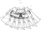
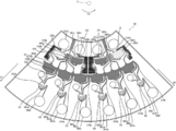
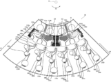
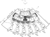
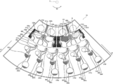
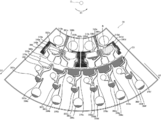
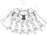
- FIG. 1 is a schematic top view showing an example of a dispensing apparatus.
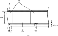
- FIG. 2A is a schematic view showing a cross-sectional structure taken along line L1-L1 of the dispensing device shown in FIG.
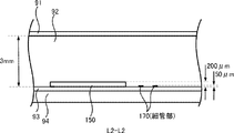
- FIG. 2B is a schematic view showing a cross-sectional structure taken along line L2-L2 of the dispensing device shown in FIG.
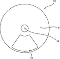
- FIG. 3 is a schematic top view showing an example of a state in which the dispensing device shown in FIG. 1 is mounted on a disk drive.
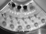
- FIG. 4 is a photograph showing the dispensing apparatus of the present embodiment.
- FIG. 5 is a photograph showing a disk drive on which the dispensing apparatus of the present embodiment is placed.
- FIG. 6A is a schematic view showing the movement of the fluid sample A when the dispensing device shown in FIG. 1 dispenses.
- FIG. 6B is a schematic view showing the movement of the fluid sample A when the dispensing device shown in FIG. 1 dispenses.
- FIG. 6C is a schematic view showing the movement of the fluid sample A when the dispensing device shown in FIG. 1 dispenses.
- FIG. 6D is a schematic view showing the movement of fluid sample A when dispensing by the dispensing device shown in FIG.
- FIG. 6E is a schematic view showing the movement of the fluid sample A when the dispensing device shown in FIG. 1 dispenses.
- FIG. 6F is a schematic view showing the movement of the fluid sample A when the dispensing device shown in FIG.
- FIG. 6G is a schematic view showing the movement of the fluid sample A when the dispensing device shown in FIG. 1 dispenses.
- FIG. 6H is a schematic view showing the movement of the fluid sample A when the dispensing device shown in FIG. 1 dispenses.
- FIG. 6I is a schematic view showing the movement of fluid sample A during dispensing by the dispensing device shown in FIG.
- FIG. 6J is a schematic view showing the movement of the fluid sample A when dispensing by the dispensing device shown in FIG.
- FIG. 6K is a schematic view showing the movement of the fluid sample A when the dispensing device shown in FIG. 1 dispenses.
- FIG. 6G is a schematic view showing the movement of the fluid sample A when the dispensing device shown in FIG. 1 dispenses.
- FIG. 6H is a schematic view showing the movement of the fluid sample A when the dispensing device shown in FIG. 1 dispenses.
- FIG. 6I is a schematic view showing the movement of fluid
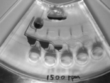
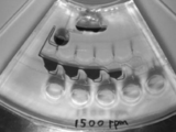
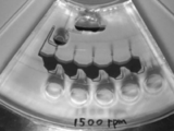
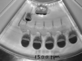
- FIG. 7A is a still image included in moving image data obtained by capturing the movement of the fluid sample A when the dispensing device shown in FIGS. 1 and 6A to 6K actually dispenses.
- FIG. 7B is a still image included in moving image data obtained by capturing the movement of the fluid sample A when the dispensing device shown in FIGS. 1 and 6A to 6K actually dispenses.
- FIG. 7C is a still image included in moving image data obtained by imaging the movement of the fluid sample A when the dispensing device shown in FIGS. 1 and 6A to 6K actually dispenses.
- FIG. 7D is a still image included in moving image data obtained by capturing the movement of the fluid sample A when the dispensing device shown in FIGS.
- FIG. 7E is a still image included in moving image data obtained by capturing the movement of the fluid sample A when the dispensing device shown in FIGS. 1 and 6A to 6K actually dispenses.
- FIG. 7F is a still image included in moving image data obtained by capturing the movement of the fluid sample A when the dispensing device shown in FIGS. 1 and 6A to 6K actually dispenses.
- FIG. 7G is a still image included in moving image data obtained by capturing the movement of the fluid sample A when the dispensing device shown in FIGS. 1 and 6A to 6K actually dispenses.
- FIG. 7E is a still image included in moving image data obtained by capturing the movement of the fluid sample A when the dispensing device shown in FIGS. 1 and 6A to 6K actually dispenses.
- FIG. 7F is a still image included in moving image data obtained by capturing the movement of the fluid sample A when the dispensing device shown in FIGS. 1 and 6A to 6K actually dispenses.
- FIG. 7H is a still image included in moving image data obtained by capturing the movement of the fluid sample A when the dispensing device shown in FIGS. 1 and 6A to 6K actually dispenses.
- FIG. 7I is a still image included in moving image data obtained by capturing the movement of the fluid sample A when the dispensing device shown in FIGS. 1 and 6A to 6K actually dispenses.
- FIG. 7J is a still image included in moving image data obtained by capturing the movement of the fluid sample A when the dispensing device shown in FIGS. 1 and 6A to 6K actually dispenses.
- FIG. 7K is a still image included in moving image data obtained by capturing the movement of the fluid sample A when the dispensing device shown in FIGS.
- FIG. 8 is a graph showing the results of determination of the change coefficient of the amount of fluid sample dispensed by the dispensing apparatus shown in FIGS. 7A to 7K.
- FIG. 9 is a view showing an example of a dispensing apparatus having no transfer means.
- FIG. 10 is a still image included in moving image data obtained by capturing the movement of the fluid sample A when the dispensing device shown in FIG. 9 actually dispenses.
- FIG. 11 is a graph showing the result of finding the change coefficient of the amount of fluid sample dispensed by the dispensing device shown in FIGS. 9 and 10.
- FIG. 12 is a schematic top view showing an example of an inspection apparatus used in an analysis process for detecting a protein.
- FIG. 12 is a schematic top view showing an example of an inspection apparatus used in an analysis process for detecting a protein.
- FIG. 13A is a schematic view showing the movement of each liquid when the test device shown in FIG. 12 tests a protein contained in a sample solution.
- FIG. 13B is a schematic view showing the movement of each liquid when the test device shown in FIG. 12 tests the proteins contained in the sample solution.
- FIG. 13C is a schematic view showing the movement of each liquid when the test device shown in FIG. 12 tests the proteins contained in the sample solution.
- FIG. 13D is a schematic view showing the movement of each liquid when the test device shown in FIG. 12 tests the proteins contained in the sample solution.
- FIG. 13E is a schematic view showing the movement of each liquid when the test device shown in FIG. 12 tests the proteins contained in the sample solution.
- FIG. 13F is a schematic view showing the movement of each liquid when the test device shown in FIG.
- FIG. 13G is a schematic view showing the movement of each liquid when the test device shown in FIG. 12 tests a protein contained in a sample solution.
- FIG. 13H is a schematic view showing the movement of each liquid when the test device shown in FIG. 12 tests a protein contained in a sample solution.
- FIG. 13I is a schematic view showing the movement of each liquid when the test device shown in FIG. 12 tests the proteins contained in the sample solution.
- FIG. 13J is a schematic view showing the movement of each liquid when the test device shown in FIG. 12 tests a protein contained in a sample solution.
- FIG. 13K is a schematic view showing the movement of each liquid when the test device shown in FIG. 12 tests a protein contained in a sample solution.
- FIG. 13L is a schematic view showing the movement of each liquid when the test device shown in FIG. 12 tests a protein contained in a sample solution.
- FIG. 13M is a schematic view showing the movement of each liquid when the test device shown in FIG. 12 tests a protein contained in a sample solution.
- FIG. 13N is a schematic view showing the movement of each liquid when the test device shown in FIG. 12 tests a protein contained in a sample solution.
- FIG. 13O is a schematic view showing the movement of each liquid when the test device shown in FIG. 12 tests a protein contained in a sample solution.
- FIG. 14A is a still image included in moving image data obtained by imaging the movement of each liquid when the inspection apparatus shown in FIGS. 12 and 13A to 13O actually performs inspection.
- FIG. 14A is a still image included in moving image data obtained by imaging the movement of each liquid when the inspection apparatus shown in FIGS. 12 and 13A to 13O actually performs inspection.
- FIG. 14A is a still image included in moving image data obtained by
- FIG. 14B is a still image included in moving image data obtained by capturing the movement of each liquid when the inspection apparatus shown in FIGS. 12 and 13A to 13O actually performs inspection.
- FIG. 14C is a still image included in moving image data obtained by imaging the movement of each liquid when the inspection apparatus shown in FIGS. 12 and 13A to 13O actually performs inspection.
- FIG. 14D is a still image included in moving image data obtained by capturing the movement of each liquid when the inspection apparatus shown in FIGS. 12 and 13A to 13O actually performs inspection.
- FIG. 14E is a still image included in moving image data obtained by imaging the movement of each liquid when the inspection apparatus shown in FIGS. 12 and 13A to 13O actually performs inspection.
- FIG. 14C is a still image included in moving image data obtained by imaging the movement of each liquid when the inspection apparatus shown in FIGS. 12 and 13A to 13O actually performs inspection.
- FIG. 14D is a still image included in moving image data obtained by capturing the movement of each liquid when the inspection apparatus
- FIG. 14F is a still image included in moving image data obtained by capturing the movement of each liquid when the inspection apparatus shown in FIGS. 12 and 13A to 13O actually performs inspection.
- FIG. 14G is a still image included in moving image data obtained by capturing the movement of each liquid when the inspection apparatus shown in FIGS. 12 and 13A to 13O actually performs inspection.
- FIG. 14H is a still image included in moving image data obtained by imaging the movement of each liquid when the inspection apparatus shown in FIGS. 12 and 13A to 13O actually performs inspection.
- FIG. 14I is a still image included in moving image data obtained by capturing the movement of each liquid when the inspection apparatus shown in FIGS. 12 and 13A to 13O actually performs inspection.
- FIG. 14F is a still image included in moving image data obtained by capturing the movement of each liquid when the inspection apparatus shown in FIGS. 12 and 13A to 13O actually performs inspection.
- FIG. 14G is a still image included in moving image data obtained by capturing the movement of each liquid when the
- FIG. 14J is a still image included in moving image data obtained by imaging the movement of each liquid when the inspection apparatus shown in FIGS. 12 and 13A to 13O actually performs inspection.
- FIG. 14K is a still image included in moving image data obtained by capturing the movement of each liquid when the inspection apparatus shown in FIGS. 12 and 13A to 13O actually performs inspection.
- FIG. 14L is a still image included in moving image data obtained by capturing the movement of each liquid when the inspection apparatus shown in FIGS. 12 and 13A to 13O actually performs inspection.
- FIG. 14M is a still image included in moving image data obtained by imaging the movement of each liquid when the inspection apparatus shown in FIGS. 12 and 13A to 13O actually performs inspection.
- FIG. 14K is a still image included in moving image data obtained by imaging the movement of each liquid when the inspection apparatus shown in FIGS. 12 and 13A to 13O actually performs inspection.
- FIG. 14N is a still image included in moving image data obtained by capturing the movement of each liquid when the inspection apparatus shown in FIGS. 12 and 13A to 13O actually performs inspection.
- FIG. 14O is a still image included in moving image data obtained by imaging the movement of each liquid when the inspection apparatus shown in FIGS. 12 and 13A to 13O actually performs inspection.
- FIG. 15 is a photograph showing a scanner image of an inspection apparatus capable of detecting a protein according to the process shown in FIGS. 14A to 14O.
- FIG. 16 is a graph showing the results of analyzing the amount of protein.
- the dispensing apparatus of the present invention has a plurality of first storage units, a plurality of second storage units, and a transfer unit, and further has other units as required.
- the dispensing method of the present invention includes a first storage step, a second storage step, and a transfer step, and further includes other steps as necessary.
- the dispensing method of the present invention can be performed by the dispensing device of the present invention, and the first storage step can be performed by the plurality of first storage sections, and the second storage step can be performed by the plurality of second storage portions.
- the transfer step can be performed by the transfer means, and the other steps can be performed by the other means.
- the dispensing apparatus of the present invention even a small amount of fluid sample can be dispensed in synchronization with each other in a uniform state by a simple mechanism.
- the dispensing method of the present invention even a small amount of fluid sample can be dispensed in synchronization with each other in a uniform state by a simple method.
- the first accommodation step is a step of fractionating and accommodating the fluid sample transferred by the external force, and implemented by the plurality of first accommodation portions.
- the plurality of first accommodating portions are formed in communication with each other and are not particularly limited as long as they can separate and accommodate the fluid sample transferred by the external force, and can be appropriately selected according to the purpose.
- the plurality of first containers formed in communication with each other are formed such that the fluid sample can flow in the upper part of the plurality of first containers in series, and the whole as a single container is a fluid sample It means what can accommodate.
- the plurality of first housing portions are not particularly limited and may be appropriately selected depending on the purpose, but preferably have equal volumes.
- the dispensing apparatus stores (fills) the fluid sample in the entire plurality of first storage units, and then supplies the fluid sample to each of the first storage units.
- the size, shape, structure, number, etc. of the first containing part are not particularly limited as long as they can contain the fluid sample as the first containing part, and may be appropriately selected according to the purpose. it can. It is preferable to have the number of first accommodating parts according to the number to be dispensed as the number of first accommodating parts.
- the plurality of first storage units may be referred to as a “connected container”, and the first storage unit may be referred to as a “fractionation container”. Also, the external force applied to the connection container may be referred to as "external force A”.
- the fluid sample is not particularly limited and may be appropriately selected according to the purpose. Examples thereof include solutions containing blood, proteins, genes and the like, solutions containing solid components such as microorganisms and animal and plant cells, and various chemical substances. Environmental water, soil extraction water etc. are mentioned. Furthermore, as the fluid sample, for example, various reagents used for analysis thereof, buffer solutions, washing water and the like can be mentioned.
- centrifugal force may be applied to the dispensing device to cause force to flow the fluid sample, for example, by rotating a rotating body on which the disk-like dispensing device is mounted.
- the external force is gravity, for example, a columnar dispensing device having a structure capable of dispensing by transferring a fluid sample from one end to the other end, and one end is positioned higher than the other end when dispensing This may produce a force that causes the fluid sample to flow.
- the external force is a magnetic force, for example, a force may be generated to flow the fluid sample having magnetism by disposing an N pole on the upstream side or an S pole on the downstream side of the analyzer.
- the external force is a pressing force, for example, a force may be generated to flow the fluid sample by pressing a container filled with the fluid sample provided in the analyzer with an actuator or the like.
- the second accommodation step is a step of respectively accommodating the fluid samples fractionated in the connection container by an external force, and is performed by the plurality of second accommodation portions.
- the plurality of second accommodation units are not particularly limited, and can be appropriately selected according to the purpose.
- the plurality of second accommodation units are not particularly limited as long as they can respectively accommodate the fluid samples fractionated in the connection container by an external force, and can be appropriately selected according to the purpose.
- As the number of second accommodation units a number corresponding to the number of first accommodation units is preferable.
- the downstream is more preferable than the position of a 1st accommodating part.
- the plurality of second storage units may be referred to as a “storage container group”, and the second storage units may be referred to as a “storage container”. Also, the external force applied to the plurality of second housing portions may be referred to as "external force B”.
- the transfer step after the fluid sample is filled in the first storage step, the external force is used to transfer and store the fluid sample fractionated in the first storage step in the second storage step.
- Process and is performed by the transfer means.
- the transfer means is not particularly limited as long as it can transfer the fractionated fluid sample to the storage vessel group by an external force after the connection sample is filled with the fluid sample, and can be appropriately selected according to the purpose.
- the transfer means may also be referred to as a "transfer mechanism”.
- the external force applied to the transfer means may be referred to as "external force C".
- the transfer means transfers the fluid sample filled in the connection container in synchronization with each other with respect to the storage container group.
- to synchronize and transfer to each other means that the transfer means transfers the fluid sample, which has been filled in the connection container, at a timing that can be stored in all the storage containers. That is, it may be timing when transfer means starts to transfer the fluid sample to another storage container before transferring the fluid sample from the connection container to the one storage container.
- the dispensing device can dispense the same fluid sample filled in the connection container in a homogeneous state to the storage container group.
- a transfer means has the below-mentioned pressurized flow path and siphon structure The method of setting it as a flow path etc. are mentioned.
- a sensor for detecting that the connection container is filled with the fluid sample, and a solenoid valve for causing the connection container to flow out to the storage container group based on a detection signal from the sensor may be provided.
- a timer valve with a timer it is possible to synchronize and open the flow path at the same time when the time to fill the fluid container in the connection container is reached.
- a sensor a liquid pressure sensor, a liquid level sensor, a flow rate sensor etc. are mentioned, for example.
- a position of a solenoid valve or a solenoid valve with a timer the bottom part of each fraction container in a connection container etc.
- the pressurizing unit is not particularly limited as long as a pressure equal to or higher than a predetermined value can be applied to the fluid sample filled in the connection container, and can be appropriately selected according to the purpose.
- a flow path when a pressure higher than a predetermined value is applied to the fluid sample filled in the connection container by the pressurizing unit, there is a particular restriction as long as the fluid sample can be transferred from the connection container to the storage container group under the pressure. It can be selected appropriately according to the purpose.
- the pressure above a predetermined value means the pressure at which the flow path can not hold the fluid sample subjected to the pressure and the flow path transfers the fluid sample.
- a pressurizing part for example, a pump, an actuator, etc. may be mentioned, but from the viewpoint of not requiring a power source for operating the pump or the actuator, it is connected to the upper part of the connection container and is extended and disposed upstream thereof Pressure channels and the like.
- the pressurizing unit is a pressurized flow channel, an external force is applied to the downstream side to the fluid sample stored in the pressurized flow channel, so that the fluid sample filled in the connection container on the downstream side of the pressurized flow channel is pressurized.
- the shape of the pressurizing channel is not particularly limited and may be appropriately selected according to the purpose. For example, a column or the like can be mentioned, but pressurization is immediately started after the completion of the first accommodation step.
- a fluid sample flows into the closed container to transfer a pressurized medium which is at least one of liquid and gas and which is incompatible with the fluid sample, and pressurized.
- the fluid sample filled in the connection container may be pressurized by the pressure of the medium.
- the flow path is not particularly limited as long as it can pressurize the fluid sample filled in the connection container after the pressurizing section pressurizes the fluid sample from the connection container to the storage container group under the application of pressure, depending on the purpose.
- the flow path which has a valve function which can be opened and closed by pressurization of a pressurization part is preferred.
- a flow path which has a valve function a flow path etc. which have at least one of a siphon structure and a capillary structure in part, etc. are mentioned, for example.
- a channel having a siphon structure for example, a channel having a hairpin-shaped bend on the upstream side can be mentioned.
- the pressurizing unit is a pressurizing channel and the channel is a channel having a siphon structure
- the pressure applied from the pressurizing channel to the fluid sample filled in the connection container is a fluid according to the Pascal principle. Transfer to all other parts of the sample. For this reason, the pressure applied to the fluid sample from the pressurized flow channel is uniformly applied to the flow channels having the respective siphon structures. Therefore, if the flow channels having the siphon structures are similar to each other, they are mutually synchronized. Fluid sample can be transported.
- the dispensing apparatus can transfer and dispense the receiving container group from each flow path in synchronization with each other by applying a pressure equal to or higher than a predetermined value to the fluid sample filled in the connection container. .
- ⁇ Other means> As other means, for example, an introducing part, a time adjusting means, a vent and the like can be mentioned.
- the introduction unit is not particularly limited as long as it can introduce and accommodate a fluid sample and can transfer the fluid sample to the connection container by an external force, and can be appropriately selected according to the purpose.
- the time adjustment means is disposed between the respective parts, and the passage time of the fluid sample can be adjusted to be long by making the length of the flow path longer and the diameter smaller than that of the linear flow path.
- a shape of a time adjustment means According to the objective, it can select suitably, For example, what has a zigzag shape, a siphon structure, etc. are mentioned.
- the vent is disposed upstream of each part of the dispensing device and is open to the atmosphere. Thereby, the vent can release the air in each part even if the fluid sample flows into each part, and can transfer the fluid sample smoothly.
- a preparation method of a dispensing apparatus there is no restriction
- connection container a storage container group, and a transfer means may be integral, At least any one is another body Or each may be separate.
- positioned on a rotatable rotary body is preferable, for example, flat form
- the shape may be a disk shape or the like, or may be a shape (so-called "Round shape") cut at a predetermined angle from the center of the disk-like circle.
- a shape of another dispensing apparatus it is good also as stick shape etc., for example from a viewpoint which can use a centrifuge.
- the size of the disk-like dispensing device may be the same as that of a compact disc (CD), a digital video disc (DVD), or the like, from the viewpoint of easy handling by hand.
- the centrifugal force as an external force can be efficiently applied to the dispensing device as the shape of the dispensing device is a shape that can be disposed on the rotatable rotating body.
- the rotating body is not particularly limited and may be appropriately selected according to the purpose.
- the dispensing device is a disc-like disc, one having a mechanism for rotating the disc-like disc, etc. It is suitable. Centrifugal force can be applied to the dispensing device by rotating the rotating body on which the dispensing device is mounted.
- the dispensing device and the inspection device may be connected and set on the rotating body, and the inspection may be automatically performed at one time until the inspection object is inspected using the dispensed fluid sample.
- the inspection can be performed using the dispensed fluid sample in a state in which the same external force as the external force applied to the dispensing device is applied to the inspection by the inspection device.
- the rotating body is controlled by the control means.
- the control means is not particularly limited as long as the operation of the rotating body can be controlled by a motor or the like, and can be appropriately selected according to the purpose. Examples thereof include devices such as sequencers and computers. There is no restriction
- the dispensing apparatus can dispense in synchronization with one another in a homogeneous state even if it is a small amount of fluid sample, by a simple mechanism of the connection container, the storage container group, and the transfer means.
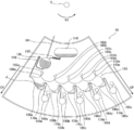
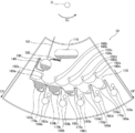
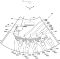
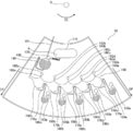
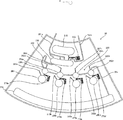
- FIG. 1 is a schematic top view showing an example of the dispensing device 10.
- the dispensing apparatus 10 includes a first reservoir 110, a second reservoir 130, a connection chamber 150 as a connection container, and pressure channels 160a to 160e as pressure units of transfer means. It has siphon structured flow channels 170a to 170e as the flow channels of the transfer means, and storage chambers 180a to 180e as the storage container group. Between the first reservoir 110 and the second reservoir 130, there is a serpentine curved channel 120.
- a siphon flow channel 140 is provided between the second reservoir 130 and the connection chamber 150.
- the dispensing device 10 rotates around the rotational axis position O, and centrifugal force CF as an external force is generated from the rotational axis position O as a starting point. And the opposite side of the rotational axis position O of each part is referred to as the lower or downstream.
- the first reservoir 110 is disposed at the most upstream of the respective parts, and contains the fluid sample A introduced by the user.
- the first reservoir 110 causes the fluid sample A to flow out to the second reservoir 130 via the curved flow passage 120 disposed downstream when centrifugal force is applied.
- a siphon flow channel 140 is provided downstream of the second reservoir 130.
- the bent portion of the siphon flow channel 140 is located above the second reservoir 130. For this reason, in the second reservoir 130, the fluid sample A is measured once. And, when the centrifugal force CF is applied to the second reservoir 130, when the fluid sample A flowing from the first reservoir 110 exceeds the bending portion of the siphon flow channel 140, the siphon structure flow channel 140 is It flows out to the connection chamber 150 via
- the connection chamber 150 has a plurality of fractionating chambers 150a to 150e as a first accommodation portion formed in communication with one another, and fractionates and accommodates the fluid sample A flowing out of the second reservoir 130.
- the fractionation chambers 150a to 150e have equal volumes, respectively, and pressurized flow channels 160a to 160e are provided on the upper portions thereof.
- the pressurizing channels 160a to 160e accommodate the fluid sample A flowing out of the second reservoir 130 after the connection chamber 150 is filled with the fluid sample A. Therefore, when the centrifugal force CF is applied, the centrifugal force CF is applied downstream to the fluid sample A accommodated in the pressurized flow channels 160a to 160e, so that the connection located on the downstream side of the pressurized flow channels 160a to 160e The fluid sample A filled in the chamber 150 is pressurized.
- the siphon structured flow channels 170a to 170e are respectively connected between the fractionation chambers 150a to 150e of the connection chamber 150 disposed on the upstream side and the storage chambers 180a to 180e disposed on the downstream side.
- the bent portions of the siphon structured flow channels 170a to 170e are located below the communication portion of the connection chamber 150, but the diameter is narrowed. Therefore, the connection chamber 150 can accommodate the fluid sample A up to the upper side of the bending portion of the siphon flow channels 170a to 170e even when the centrifugal force CF is applied.
- the siphon structure flow channels 170a to 170e are filled with the fluid sample A flowing from the second reservoir 130, and when the fluid sample A is accommodated in the pressure flow channels 160a to 160e, the fluid filled in the connection chamber 150
- the sample A is pressurized by the fluid sample A accommodated in the pressurizing channels 160a to 160e.
- the meniscus of the fluid sample A passes over the bend of the siphon structured flow channels 170a to 170e, and the fluid sample A filled in the connection chamber 150 is transferred to the storage chambers 180a to 180e by the principle of siphon.
- the storage chambers 180a to 180e respectively store the fluid sample A fractionated in the fractionation chambers 150a to 150e. Thus, dispensing of the fluid sample A is completed.
- the vent 191, the vents 192a to 192e, and the vents 193a to 193e are provided on the upstream side of each part, and even if the fluid sample flows into each part, the air in each part is released. Fluid sample can flow smoothly into each part.
- FIG. 2A is a schematic view showing a cross-sectional structure taken along line L1-L1 of the dispensing device 10 shown in FIG. 1, and shows a cross-sectional structure of the first reservoir 110 and the curved flow passage 120 shown in FIG.
- the dispensing apparatus 10 has a polydimethylsiloxane (PDMS) sheet (PDMS sheet) 93, a PDMS layer 92, and a cover layer 91 laminated in this order on a substrate portion 94. It is a layered structure.
- the PDMS layer 92 is processed by the lithography method to form the first reservoir 110 and the curved flow passage 120.
- the processing depth of the first reservoir 110 is 3 mm as in the thickness of the PDMS layer 92, and the processing depth of the curved flow passage 120 is 100 ⁇ m.
- FIG. 2B is a schematic view showing a cross-sectional structure taken along line L2-L2 of the dispensing device 10 shown in FIG. 1, and shows a cross-sectional structure of the connection chamber 150 and the siphon structure flow channel 170 shown in FIG.
- the cross section of the connection chamber 150 and the siphon flow channel 170 also has the same layer structure as that of FIG. 2A, and the PDMS layer 92 is processed by lithography. Is formed.
- the processing depth of the connection chamber 150 is 200 ⁇ m, and the processing depth of a narrow portion (thin tube portion) of the siphon flow channel 170 is 50 ⁇ m.
- the processing depth of the thick part of the siphon structure flow path 170 is 100 micrometers.
- FIG. 3 is a schematic top view showing an example of a state in which the dispensing device 10 shown in FIG. 1 is mounted on the disk drive device 50.
- the disk drive device 50 has a disk mounting table 51 as a rotating body, and a plurality of dispensing devices 10 can be mounted on the disk mounting table 51.
- a hole 52 for receiving the rotation shaft of the disk drive device 50 for rotating the disk mounting table 51.
- the position of the hole 52 corresponds to the rotation axis position O shown in FIG.
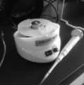
- FIG. 4 is a photograph showing the dispensing apparatus 10 of the present embodiment
- FIG. 5 is a photograph showing a disk drive apparatus on which the dispensing apparatus 10 of the present embodiment is placed.
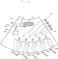
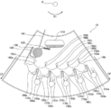
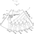
- FIG. 6A to 6K are schematic views showing the movement of the fluid sample A when the dispensing device shown in FIG. 1 dispenses.
- 50 ⁇ L of (0.2% Victoria Blue-containing ion-exchanged water) as fluid sample A is introduced into the first reservoir 110 using a pipette.
- the dispensing device 10 is placed on the disk 90 and fixed (see FIG. 3), and as shown in FIG. 6B, the dispensing device 10 is rotated at 1,500 rpm in the rotational direction R1. Is applied, the fluid sample A flows into the second reservoir 130. At this time, since the second reservoir 130 has the vent 191, the fluid sample A smoothly flows into the second reservoir 130 and reaches the siphon flow channel 140.
- fluid sample A fills the second reservoir 130 and passes through the bent portion of the siphon flow channel 140, whereby the siphon principle works, Since the flow rate discharged from the second reservoir 130 is sufficiently larger than the flow rate injected into the second reservoir 130, the amount of the fluid sample A in the connection chamber 150 is approximately equal to the volume of the second reservoir 130. To flow. Then, as shown in FIGS. 6D to 6H, the fluid sample A is accommodated in the order of the fraction chambers 150a to 150e on the left side of the connection chamber 150. At this time, the fluid sample A also reaches the siphon structured flow channels 170a to 170e disposed on the downstream side of the connection chamber 150, but does not exceed the bends of the siphon structured flow channels 170a to 170e.
- connection chamber 150 When centrifugal force CF continues to be applied, fluid sample A is filled into connection chamber 150 as shown in FIG. 6I. At this time, since the vent 192 is provided at the other end of the pressurizing channel 160, the fluid sample A can smoothly flow into the pressurizing channels 160a to 160e. Then, centrifugal force is applied to the fluid sample A flowing into the pressurizing flow channels 160a to 160e, whereby the fluid sample A flowing into the pressurizing flow channels 160a to 160e pressurizes the fluid sample A filled in the connection chamber 150. Therefore, the fluid sample A in the siphon structured flow channels 170a to 170e flows out of the bending portion toward the storage chambers 180a to 180e (see FIG. 6J).
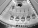
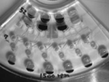
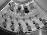
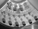
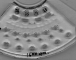
- FIGS. 7A to 7K are still images included in moving image data obtained by imaging the movement of the fluid sample A when the dispensing device shown in FIGS. 1 and 6A to 6K actually dispenses. From these results, it is understood that according to the separation device 10, even a minute amount of fluid sample can be dispensed in synchronization with each other in a uniform state by a simple mechanism.
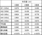
- FIG. 8 is a graph showing the result of finding the change coefficient of the amount of the fluid sample A dispensed by the dispensing device 50 shown in FIGS. 7A to 7K. As shown in FIG. 8, the variation coefficient CV of the fluid sample A dispensed into the storage chambers 180a to 180e was 3.3% to 5.6% when the dispensing was performed three times.
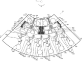
- FIG. 9 is a view showing an example of the dispensing device 20 having no transfer means.
- the dispensing device 20 includes a first reservoir 210, a second reservoir 230, a connection chamber 250, and a storage chamber 280.
- the connection chamber 250 includes connection chambers 250a to 250d, and is formed in communication with the connection chambers 250a to 250d.
- the storage chamber group 280 includes storage chambers 280a to 280d.
- the connection chambers 250a to 250d are respectively connected to the storage chambers 280a to 280d via the curved flow paths 270a to 270d.
- a curved flow path 220 Between the first reservoir 210 and the second reservoir 230, there is a curved flow path 220. Between the second reservoir 230 and the connection chamber 250, a curved flow path 240 is provided. Further, vents 292a to 292d are connected to the connection chambers 250a to 250d on the upstream side, respectively. Vents 293a to 293d are connected upstream of the storage chambers 280a to 280d, respectively. In addition, although the dispensing apparatus 20 was rotated centering
- fluid sample A is introduced into the first reservoir 210 of the dispensing device 20 using a pipette, and then the dispensing device 20 is rotated. When centrifugal force was applied, fluid sample A was dispensed into storage chambers 280a to 280d.
- FIG. 10 is a still image included in moving image data obtained by capturing the movement of the fluid sample A when the dispensing device 20 shown in FIG. 9 actually dispenses. As shown in FIG. 10, according to the dispensing apparatus 20, it can be understood that even a minute amount of fluid sample can be easily dispensed.
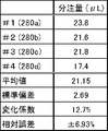
- FIG. 11 is a graph showing the result of finding the change coefficient of the amount of fluid sample A dispensed by the dispensing apparatus 20 shown in FIGS. 9 and 10.
- the variation coefficient CV of the amount of the fluid sample A dispensed into the storage chambers 280a to 280d was 12.7% when the dispensing operation was performed once.
- the variation coefficient CV in the dispensing apparatus 10 having the siphon mechanism shown in FIG. 8 it can be confirmed that the dispensing apparatus 10 having the siphon mechanism has less variation in the dispensing amount.
- the dispensing apparatus is a minute amount of fluid sample by the simple mechanism of the plurality of first storage units (connection containers), the plurality of second storage units (storage container groups), and the transfer means. Even in the homogeneous state, they can be dispensed in synchronization with each other.
- the inspection method of the present invention includes a dispensing step and an inspection step, and further includes other steps as necessary.
- the inspection apparatus of the present invention includes a dispensing unit and an inspection unit, and further includes other units as necessary.
- the inspection method of the present invention can be performed by the inspection apparatus of the present invention, the dispensing process can be performed by the dispensing unit, the inspection process can be performed by the inspection unit, and the other processes are performed by the other units. Can be done by
- a dispensing step including the dispensing method of the present invention can be used, and the contents thereof are as described above.
- the dispensing unit a dispensing unit including the dispensing device of the present invention can be used, and the contents thereof are as described above.
- the inspection process is a process of performing an inspection using the dispensing target dispensed in the dispensing process, and is performed by the inspection unit.
- the inspection unit is not particularly limited as long as it can inspect the dispensing target, and can be appropriately selected according to the purpose. For example, a minute flow path structure or a valve structure is accumulated. A micro integrated system (Micro Total Analysis System: ⁇ TAS) etc. is mentioned suitably.
- the inspection unit preferably performs the inspection using the dispensing target in a state in which the same external force as the external force applied to the dispensing unit is applied. As a result, after the dispensing apparatus dispenses the dispensing target by the dispensing unit, the inspection apparatus can continuously inspect the obtained dispensing target at the examining unit.
- the inspection unit it is preferable to have a flow path for transferring the dispensing target dispensed by the dispensing unit to the inspection unit between the dispensing unit and the inspection unit.
- the plurality of second storage units of the dispensing device may be used as the inspection unit.
- control process etc. are mentioned, for example.
- a control part etc. are mentioned, for example.
- the control unit is not particularly limited as long as the movement of each unit can be controlled, and can be appropriately selected according to the purpose. Examples thereof include devices such as sequencers and computers.
- the inspection apparatus can easily inspect a plurality of inspection objects using the dispensing apparatus.
- the dispensing device of the present invention is the dispensing device of the present invention and the dispensing device used in any of the inspection devices of the present invention.
- the dispensing device includes an introducing unit, a connection container, a container group, a transfer mechanism, and further includes other units as necessary.
- the introducing unit is not particularly limited as long as it can introduce a fluid sample, and can be appropriately selected according to the purpose. Examples thereof include a fluid sample introducing container, a reservoir, and the like.
- the connection container is not particularly limited as long as it has a plurality of fraction containers which are formed in communication with each other and can divide and store the fluid sample transferred by an external force, and may be appropriately selected according to the purpose. For example, it is similar to the plurality of first accommodation units in the dispensing device.
- the storage container group is not particularly limited as long as it has a plurality of storage containers for storing the fluid samples fractionated by the connection container, and can be appropriately selected according to the purpose.
- a dispensing apparatus are the same as the plurality of second housings in The transfer mechanism is not particularly limited as long as the fractionated fluid sample can be transferred to the storage vessel group after the fluid sample is filled in the connection vessel, and can be appropriately selected according to the purpose, for example, dispensing It is similar to the transfer means in the device.
- the transfer mechanism it is preferable to have a pressurized flow channel and a siphon structured flow channel.
- the pressure channel is not particularly limited as long as a pressure equal to or higher than a predetermined value can be applied to the fluid sample after filling the connection container, and can be appropriately selected according to the purpose. For example, pressurization of the dispensing device It is the same as the department.
- the siphon structured flow channel as long as the fluid sample can be discharged from the connection container to the storage container group when a pressure equal to or higher than a predetermined value is applied to the fluid sample filled in the connection container. It can be selected, for example, similar to the flow path of the dispensing device.
- the dispensing device preferably has the above configuration, and is a disposable, disposable item with excellent safety.
- a dispensing device may be combined with a driving device or the like of a rotating body to configure a dispensing device, or an inspection unit configured to be combined with an inspection unit that inspects a dispensing target dispensed by the dispensing device. You can also.
- FIG. 12 is a schematic top view showing an example of an inspection apparatus 30 used in an analysis process for detecting a protein.
- the inspection apparatus 30 includes first reservoirs 310a to 310d, second reservoirs 330a to 330d, a connection chamber 350 as a connection container, and pressure channels 360a to 360a as pressure units of transfer means. 360f, siphon structured flow channels 370a to 370f as flow channels of transfer means, and reaction chambers 382a to 382f as storage container groups. Further, the inspection apparatus 30 has sample introduction chambers 381a to 381f and waste liquid chambers 384a to 384f.
- Bent flow channels 320a to 320d are provided between the first reservoirs 310a to 310d and the second reservoirs 330a to 330d, respectively. Bent flow channels 340a to 340d are provided between the second reservoirs 330a to 330d and the connection chamber 350, respectively. Siphon structured flow channels 383a to 383d are provided between the reaction chambers 382a to 382f and the waste liquid chambers 384a to 384f, respectively.
- the inspection device 30 rotates about the rotational axis position O as in the dispensing device 10, and centrifugal force CF as an external force is generated from the rotational axis position O as a starting point.
- the O side is referred to as the upper side or the upstream side, and the side opposite to the rotational axis position O of each part is referred to as the lower side or the downstream side.
- the first reservoirs 310a to 310d are arranged at the most upstream side among the respective parts.
- 55 ⁇ L of each of the washing solutions C1 to C3 Phosphate Buffered Saline: PBS
- 55 ⁇ L of a chromogenic substrate solution B tetramethylbenzidine (TMBZ)
- TMBZ tetramethylbenzidine
- the viscosity of the washing solutions C1 to C3 is lower than that of the chromogenic substrate solution B.
- the viscosity of the cleaning solutions C1 to C3 is 0.99 mPa ⁇ s
- the viscosity of the color development substrate solution B is 2.03 mPa ⁇ s.
- the cleaning fluid C1, the cleaning fluid C2, the cleaning fluid C3, and the color developing substrate solution B are sequentially distributed downstream from the first reservoirs 310a to 310d in this order.
- the length and diameter of each solution are adjusted in consideration of the viscosity of each solution so that the next solution will flow out after dispensing of the solution that has flowed out to 330 d and further drained earlier in the connection chamber 350 downstream. .
- the second reservoirs 330a to 330d respectively receive the cleaning solutions C1 to C3 and the chromogenic substrate solution B which flow in at the timing adjusted by the curved flow channels 320a to 320d when the centrifugal force CF is applied. Then, the second reservoirs 330a to 330d sequentially flow the stored cleaning solutions C1 to C3 and the chromogenic substrate solution B into the connection chamber 350 through the curved flow paths 340a to 340d.
- connection chamber 350 has a plurality of fraction chambers 350a to 350f as a plurality of first accommodation portions formed in communication with one another.
- the connection chamber 350 separates the washing liquid C1, the washing liquid C2, the washing liquid C3, and the color development substrate solution B in this order when the centrifugal force CF is applied, the timing being adjusted by the curved flow paths 320a to 320d.
- the fractionation chambers 350a to 350f have equal volumes respectively, and pressurized flow channels 360a to 360f are provided on the upper side thereof.
- the siphon structured flow channels 370a to 370f are the same as the siphon structured flow channels 170a to 170e, and the washing liquid C1, the washing liquid C2, the washing liquid C3 and the coloring substrate solution B filled in the connecting chamber 350 in this order It is made to flow out into the reaction chambers 382a to 382f respectively.
- the sample introduction chambers 381a to 381f introduce and store the sample solution, and are disposed on the upstream side of the reaction chambers 382a to 382f.
- the sample introduction chambers 381a to 381f immediately discharge the sample solution to the reaction chambers 382a to 382f when the centrifugal force CF is applied.
- the reaction chambers 382a to 382f are connected to the connection chamber 350 and the sample introduction chambers 381a to 381f on the upstream side, and are connected to the waste fluid chambers 384a to 384f on the downstream side.
- a capture antibody was fixed in advance, and a detection labeled antibody was applied.
- the labeled antibody for detection is one in which an antibody is labeled with an enzyme or a fluorescent dye, and in this example, HRP (Horse Radish Peroxidase) was used.
- the present invention is not limited to this, and an object such as microbeads on which the antibody has been immobilized and blocked in advance may be disposed in the reaction chamber.
- the antibodies are not particularly limited and may be appropriately selected according to the purpose. The same antibody may be immobilized in each reaction chamber, and different antibodies may be immobilized in each reaction chamber. May be
- the waste fluid chambers 384a to 384f are disposed most downstream, and store waste fluid that has flowed out of the reaction chambers 382a to 382f.
- FIG. 13A to 13O are schematic views showing the movement of each liquid when the inspection apparatus 30 shown in FIG. 12 inspects the proteins contained in the sample solutions S1 to S6.
- 7 ⁇ L of rat IgG as sample solutions S1 to S6 was introduced into the sample introduction chambers 381 a to 381 f using a pipette.
- the sample solutions S1 to S6 were introduced in a sufficient amount not more than the volume of the reaction chambers 382a to 382f.
- the sample solutions S1 to S6 were prepared by mixing in advance a detection antibody (HRP-labeled anti-rat IgG antibody) and an antigen (rat IgG) prepared to an arbitrary concentration.
- the inspection device 30 is placed on and fixed to the disk 90, and rotated at 1,500 rpm in the rotational direction R1 as shown in FIG.
- centrifugal force CF When centrifugal force CF is applied, the sample solutions S1 to S6 flow into the reaction chambers 382a to 382f. At this time, since the reaction chambers 382a to 382f have the vents 393, the sample solutions S1 to S6 smoothly flow into the reaction chambers 382a to 382f.
- the centrifugal force CF is applied, the sample solutions S1 to S6 flow into the reaction chambers 382a to 382f, respectively, and the immune reaction is incubated to form an immune complex.
- the time for which the immune reaction is incubated is the time for the wash fluid C1 to flow into the reaction chambers 382a to 382f.
- the cleaning solutions C1 to C3 are sequentially flowed into the reaction chambers 382a to 382f to wash out the sample solutions S1 to S6, thereby cleaning the reaction chambers 382a to 382f.
- the sum of the volume of the cleaning liquid C1 and the volume of the sample solutions S1 to S6 in the reaction chambers 382a to 382f is equal to or more than the volume of the reaction chambers 382a to 382f.
- the cleaning liquid C2 dispensed by the connection chamber 350 is injected into the reaction chambers 382a to 382f.
- the cleaning liquid C2 does not reach the water level above the bending portion of the siphon, and therefore is held in the reaction chambers 382a to 382f.
- the cleaning liquid C3 dispensed by the connection chamber 350 flows into the reaction chambers 382a to 382f, the sum of this volume and the volume of the cleaning liquid 2 in the reaction chambers 382a to 382f becomes greater than or equal to the volume of the reaction chambers 382a to 382f .
- the reaction chambers 382a to 382f are mixed by the washing solution C1 and the sample solution B, the mixed solution is discharged from the reaction chambers 382a to 382f by the siphon structured flow channels 383a to 383d connected downstream of the reaction chambers 382a to 382f. As a result, unbound labeled antibody etc. are removed.
- the test substance attached to the reaction chambers 382a to 382f reacts with the capture antibody and the detection labeled antibody.
- the color development of the substance is promoted, and a color development signal corresponding to the amount of immune complex is obtained. That is, when the concentration of protein increases, the chromogenic substrate develops a blue color.
- scanning is performed in a state in which TMBZ is colored blue in order to perform image analysis.
- TMBZ is taken out and mixed with 1 M (mol / L) sulfuric acid H 2 SO 4 in a 1: 1 ratio to stop the coloring reaction, and the termination treatment is performed.
- the degree of color development is measured by a plate reader while the color development is stopped in this way.
- the image analysis data and the absorbance value obtained by these measurements are plotted to measure the calibration curve of the test substance.
- FIGS. 14A to 14O are still images included in moving image data obtained by imaging the movement of each liquid when the inspection apparatus 30 shown in FIGS. 12 and 13A to 13O actually performs inspection. From these results, according to the inspection device 30, a plurality of inspection objects can be easily inspected using the dispensing device.
- FIG. 15 is a photograph showing a scanner image of the inspection apparatus 30 capable of detecting a protein by the process shown in FIGS. 14A to 14O. Since the test was carried out by increasing the concentration of protein in the order of the sample solutions S1 to S6, it can be seen that the color is developed in the order of the reaction chambers 382a to 382f in a dark order as shown in FIG.
- FIG. 16 is a graph showing the results of analyzing the amount of protein.
- the line plotted by “x” in FIG. 16 indicates the signal strength of R of RGB information obtained by image analysis of the scanner image shown in FIG.
- the line plotted by " ⁇ ” in FIG. 16 shows the result of measuring the optical density (Optical Density: OD value) of the reaction chamber of the inspection apparatus 30 using Multiskan GO manufactured by Thermo fisher scientific.
- OD value optical Density
- the inspection apparatus can easily inspect a plurality of inspection objects using the dispensing apparatus. Further, in the present embodiment, the amount of protein was changed in the sample solution, but the sample solution may be the same without being limited thereto. Furthermore, in the conventional inspection, in order to evaluate the analysis result by interrogating the measured numerical value and the calibration curve measured in advance, it was necessary to match the calibration curve to the environmental conditions under which the calibration curve was measured. When the inspection apparatus of the present invention is used, a calibration curve can be created simultaneously for each measurement, so that the reliability of the inspection can be improved.
- the aspect of the present invention is, for example, as follows.
- a plurality of first containing portions that are formed in communication with each other and can divide and store the fluid sample transferred by an external force;
- a plurality of second containing sections respectively containing the fluid samples fractionated by the plurality of first containing sections;
- a transfer unit configured to transfer the fluid sample to the second storage unit after the fluid sample is stored in the plurality of first storage units;
- It is a dispensing apparatus characterized by having.
- ⁇ 2> The dispensing apparatus according to ⁇ 1>, wherein the plurality of first storage units have equal volumes.
- the transfer means is A pressure unit that applies a pressure equal to or greater than a predetermined value to the fluid sample after being accommodated in the first accommodation unit; When a pressure equal to or greater than the predetermined value is applied to the fluid samples contained in the plurality of first containing parts, the fluid samples are supplied from the plurality of first containing parts to the plurality of second containing parts.
- a channel to transport the It is a dispensing apparatus in any one of said ⁇ 1> to ⁇ 2> which has these.
- ⁇ 5> The dispensing device according to any one of ⁇ 1> to ⁇ 4>, which is disposed on a rotatable rotary body.
- a dispensing unit comprising the dispensing device according to any one of ⁇ 1> to ⁇ 5>, An inspection unit which inspects a plurality of inspection objects using the fluid sample dispensed by the dispensing unit; It is an inspection device characterized by having.
- ⁇ 7> The inspection apparatus according to ⁇ 6>, wherein the inspection unit inspects the plurality of inspection objects in a state where an external force identical to the external force applied to the dispensing unit is applied.
- a connected container having a plurality of fractionated containers formed in communication with one another and capable of fractionating and containing a fluid sample transferred by external force;
- a storage container group having a plurality of storage containers each storing the fluid sample fractionated by the connection container;
- the transfer step Pressure treatment for applying a pressure equal to or greater than a predetermined value to the fluid sample after being accommodated in the first accommodation step; When a pressure equal to or higher than the predetermined value is applied to the fluid samples stored in the plurality of first storage units, the plurality of first storage units in the first storage step are subjected to the second storage.
- the dispensing apparatus according to any one of ⁇ 1> to ⁇ 5>, the inspection apparatus according to any one of ⁇ 6> to ⁇ 7>, the dispensing device according to ⁇ 8>, and ⁇ 9>
- the problems in the related art are solved and the object of the present invention is achieved. can do.
- pressurized flow path connected to the connection container as the pressurizing unit and extending and disposed on the upstream side
- connection container as the pressurizing unit and extending and disposed on the upstream side
- one end (one end of the pressurizing channel) of the pressurizing channel 160a to 160e
- each of the first accommodating portions fraction chambers 150a to 150e
- an external force is applied from each of the dividing chambers.
- the flow path is disposed to extend in the opposite direction to the direction.
- vents may be provided at the other end of the pressurizing channel.
- the centrifugal force CF is continuously applied to the dispensing device 10, and the fluid sample A is filled in the connection chamber 150, and as the fluid sample A flows into the pressurized flow channels 160a to 160e, pressurized flow
- the water head pressure in the paths 160a to 160e increases.
- the pressure channels 160a to 160e function to pressurize the fluid sample A filled in the connection chamber 150 by the increase of the water head pressure.
- the fluid sample flows into the closed vessel to transfer the pressurized medium which is at least one of liquid and gas and is incompatible with the fluid sample, and the connection vessel is filled with the pressure by the pressurized medium.
- air can be suitably used as the pressurizing medium.
- the pressurized air may be introduced into the above-described pressurizing flow path.
- a flow path is disposed from each of the fractionation chambers so as to extend in the direction opposite to the application direction of the external force, and then the pressure mechanism of the air medium is connected to the flow path You should do it.
- the air pressurizing mechanism may be formed on the microdevice or may be connected to an external pressurizing mechanism.
- the connection chamber 350 includes fraction chambers 350a to 350f.
- one end of each of the pressurizing channels 360a to 360f is connected to each of the fractionating chambers 350a to 350f, and vents are respectively provided to the other ends of the pressurizing channels 360a, 360c, 360d, and 360f in the pressurizing channels. 392a, 360c, 360d, and 360f are connected.
- the other ends of the pressurizing flow channels 360 b and 360 e are arranged such that the pressurizing flow channel extends to the end face on the rotation axis position (O) side of the inspection device 30.
- inspection apparatus 110 1st reservoir 130 2nd reservoir 150 connection chamber (a plurality of 1st accommodating parts) 150a to 150e fraction chamber (first container) 160a to 160e Pressurized flow path (pressurizing part of transfer means) 170a to 170e siphon structured flow path (flow path of transfer means) 180a to 180e accommodation chamber (second accommodation unit)
Landscapes
- Chemical & Material Sciences (AREA)
- Health & Medical Sciences (AREA)
- Analytical Chemistry (AREA)
- General Health & Medical Sciences (AREA)
- Immunology (AREA)
- Biochemistry (AREA)
- Life Sciences & Earth Sciences (AREA)
- General Physics & Mathematics (AREA)
- Physics & Mathematics (AREA)
- Pathology (AREA)
- Dispersion Chemistry (AREA)
- Hematology (AREA)
- Clinical Laboratory Science (AREA)
- Chemical Kinetics & Catalysis (AREA)
- Automatic Analysis And Handling Materials Therefor (AREA)
- Sampling And Sample Adjustment (AREA)
Abstract
L'invention concerne un appareil de distribution comprenant : une pluralité de premières parties d'accueil qui sont formées de manière à être en communication entre elles et qui peuvent fractionner et accueillir un échantillon de fluide transféré par une force externe, une pluralité de deuxièmes parties d'accueil destinées à accueillir respectivement les fractions d'échantillon de fluide fractionnées par la pluralité de premières parties d'accueil, et un moyen de transfert destiné, après que l'échantillon de fluide a été accueilli dans la pluralité de premières parties d'accueil, à transférer l'échantillon de fluide vers les deuxièmes parties d'accueil respectives.
Priority Applications (3)
| Application Number | Priority Date | Filing Date | Title |
|---|---|---|---|
| CN201880068183.7A CN111247433B (zh) | 2017-10-23 | 2018-10-23 | 分配设备、使用分配设备的分配装置及方法、以及检查装置及方法 |
| JP2019551166A JP7121244B2 (ja) | 2017-10-23 | 2018-10-23 | 分注デバイス、それを用いた分注装置及び方法、並びに検査装置及び方法 |
| US16/757,136 US20200341021A1 (en) | 2017-10-23 | 2018-10-23 | Dispensing device, dispensing apparatus and method using same, and inspection apparatus and method |
Applications Claiming Priority (2)
| Application Number | Priority Date | Filing Date | Title |
|---|---|---|---|
| JP2017-204602 | 2017-10-23 | ||
| JP2017204602 | 2017-10-23 |
Publications (1)
| Publication Number | Publication Date |
|---|---|
| WO2019082902A1 true WO2019082902A1 (fr) | 2019-05-02 |
Family
ID=66247464
Family Applications (1)
| Application Number | Title | Priority Date | Filing Date |
|---|---|---|---|
| PCT/JP2018/039382 Ceased WO2019082902A1 (fr) | 2017-10-23 | 2018-10-23 | Dispositif de distribution, appareil de distribution et procédé l'utilisant, et appareil et procédé d'inspection |
Country Status (4)
| Country | Link |
|---|---|
| US (1) | US20200341021A1 (fr) |
| JP (1) | JP7121244B2 (fr) |
| CN (1) | CN111247433B (fr) |
| WO (1) | WO2019082902A1 (fr) |
Cited By (1)
| Publication number | Priority date | Publication date | Assignee | Title |
|---|---|---|---|---|
| WO2023120648A1 (fr) * | 2021-12-23 | 2023-06-29 | 国立大学法人豊橋技術科学大学 | Dispositif de distribution de fluides en microcanal et dispositif à microcanaux |
Families Citing this family (1)
| Publication number | Priority date | Publication date | Assignee | Title |
|---|---|---|---|---|
| CN117085754B (zh) * | 2023-10-20 | 2024-07-23 | 天津微纳芯科技股份有限公司 | 微流控基板和微流控芯片 |
Citations (5)
| Publication number | Priority date | Publication date | Assignee | Title |
|---|---|---|---|---|
| JP2007232673A (ja) * | 2006-03-03 | 2007-09-13 | Matsushita Electric Ind Co Ltd | マイクロ流体チップ |
| JP2014021112A (ja) * | 2012-07-11 | 2014-02-03 | Samsung Electronics Co Ltd | 微細流動構造物、これを備えた微細流動装置及び該微細流動装置の制御方法 |
| JP2014032018A (ja) * | 2012-08-01 | 2014-02-20 | Panasonic Corp | 生体化学分析システム、及び、それを用いる温度調整方法 |
| JP2015092182A (ja) * | 2011-03-08 | 2015-05-14 | ユニベルシテ・ラバルUniversite Laval | 流体求心デバイス |
| JP2015206715A (ja) * | 2014-04-22 | 2015-11-19 | 凸版印刷株式会社 | 試料分析チップ |
Family Cites Families (28)
| Publication number | Priority date | Publication date | Assignee | Title |
|---|---|---|---|---|
| US4086060A (en) * | 1976-10-22 | 1978-04-25 | Jocelyn Dickson | Disposable manipulative laboratory device for transferring biological fluids |
| WO2001087487A2 (fr) * | 2000-05-15 | 2001-11-22 | Tecan Trading Ag | Dispositifs microfluidiques centrifuges a ecoulement bidirectionnel |
| US7419638B2 (en) * | 2003-01-14 | 2008-09-02 | Micronics, Inc. | Microfluidic devices for fluid manipulation and analysis |
| US20050032241A1 (en) * | 2003-02-26 | 2005-02-10 | Coassin Peter J. | Reagent dispenser and dispensing method |
| WO2004106894A2 (fr) * | 2003-05-29 | 2004-12-09 | Mds Inc., Doing Business As Mds Sciex | Appareil et procede d'administration de fractions d'une solution contenant une substance a analyser |
| JP2006105638A (ja) * | 2004-10-01 | 2006-04-20 | Hitachi High-Technologies Corp | 化学分析装置 |
| JP3699721B1 (ja) * | 2004-10-28 | 2005-09-28 | 株式会社石川製作所 | 検体試料の遠心分注方法及び遠心分注装置 |
| JP4361879B2 (ja) * | 2005-01-07 | 2009-11-11 | 株式会社日立ハイテクノロジーズ | 化学分析装置及び化学分析カートリッジ |
| JP2006267038A (ja) * | 2005-03-25 | 2006-10-05 | Konica Minolta Medical & Graphic Inc | マイクロ総合分析システム |
| JP2006284451A (ja) * | 2005-04-01 | 2006-10-19 | Konica Minolta Medical & Graphic Inc | 検体中の標的物質を分析するためのマイクロ総合分析システム |
| US7935318B2 (en) * | 2005-06-13 | 2011-05-03 | Hewlett-Packard Development Company, L.P. | Microfluidic centrifugation systems |
| DE602005012519D1 (de) * | 2005-11-08 | 2009-03-12 | Austriamicrosystems Ag | Verstärkeranordnung mit geschalteten Kapazitäten und Verfahren dazu |
| JP2007170972A (ja) * | 2005-12-21 | 2007-07-05 | Olympus Corp | 分注装置、分析装置および分注方法 |
| JP2007240413A (ja) * | 2006-03-10 | 2007-09-20 | Konica Minolta Medical & Graphic Inc | マイクロ流体チップ |
| JPWO2007116909A1 (ja) * | 2006-04-04 | 2009-08-20 | パナソニック株式会社 | 試料液分析用パネル |
| JP2007292629A (ja) * | 2006-04-26 | 2007-11-08 | Matsushita Electric Ind Co Ltd | 液体分注装置 |
| JP2007333716A (ja) * | 2006-06-19 | 2007-12-27 | Ogawa Hiroteru | 分離・秤量チップならびにその使用方法 |
| JP2009014529A (ja) * | 2007-07-05 | 2009-01-22 | Panasonic Corp | 分析用デバイス、分析用デバイスを用いる分析装置、および液体試料成分測定方法 |
| EP3521833B1 (fr) * | 2007-10-30 | 2021-05-26 | PHC Holdings Corporation | Dispositif d'analyse |
| JP2009296967A (ja) * | 2008-06-16 | 2009-12-24 | Hitachi Ltd | 小型遺伝子解析装置 |
| KR101102532B1 (ko) * | 2008-07-10 | 2012-01-03 | 삼성전자주식회사 | 시약 카트리지, 시약 카트리지를 구비하는 미세유동장치, 그 제조방법, 및 이를 이용한 시료분석방법 |
| US8562911B2 (en) * | 2010-02-05 | 2013-10-22 | Medi Medical Engineering Corp. | Centrifugal rotor and method for using the same for delivering biological sample |
| US20120314528A1 (en) * | 2011-06-08 | 2012-12-13 | Albert-Ludwigs-Universitaet Freiburg | Device, fluidic module and method for producing a dilution series |
| TWI475226B (zh) * | 2012-08-01 | 2015-03-01 | Univ Feng Chia | 利用分流結構進行生化檢測之裝置及其運作方法 |
| JP6273510B2 (ja) * | 2012-09-11 | 2018-02-07 | 国立大学法人山梨大学 | 送液方法、遠心分離法、送液装置及び遠心分離装置 |
| AU2015225844B2 (en) * | 2014-03-07 | 2019-10-24 | National Research Council Of Canada | Centrifugal microfluidic chip control |
| DE212016000165U1 (de) * | 2015-08-07 | 2018-04-16 | Poc Medical Systems Inc. | Mikrofluidikvorrichtungen |
| JP6627580B2 (ja) * | 2016-03-07 | 2020-01-08 | 株式会社島津製作所 | マイクロチップ電気泳動装置 |
-
2018
- 2018-10-23 WO PCT/JP2018/039382 patent/WO2019082902A1/fr not_active Ceased
- 2018-10-23 US US16/757,136 patent/US20200341021A1/en not_active Abandoned
- 2018-10-23 CN CN201880068183.7A patent/CN111247433B/zh active Active
- 2018-10-23 JP JP2019551166A patent/JP7121244B2/ja active Active
Patent Citations (5)
| Publication number | Priority date | Publication date | Assignee | Title |
|---|---|---|---|---|
| JP2007232673A (ja) * | 2006-03-03 | 2007-09-13 | Matsushita Electric Ind Co Ltd | マイクロ流体チップ |
| JP2015092182A (ja) * | 2011-03-08 | 2015-05-14 | ユニベルシテ・ラバルUniversite Laval | 流体求心デバイス |
| JP2014021112A (ja) * | 2012-07-11 | 2014-02-03 | Samsung Electronics Co Ltd | 微細流動構造物、これを備えた微細流動装置及び該微細流動装置の制御方法 |
| JP2014032018A (ja) * | 2012-08-01 | 2014-02-20 | Panasonic Corp | 生体化学分析システム、及び、それを用いる温度調整方法 |
| JP2015206715A (ja) * | 2014-04-22 | 2015-11-19 | 凸版印刷株式会社 | 試料分析チップ |
Cited By (1)
| Publication number | Priority date | Publication date | Assignee | Title |
|---|---|---|---|---|
| WO2023120648A1 (fr) * | 2021-12-23 | 2023-06-29 | 国立大学法人豊橋技術科学大学 | Dispositif de distribution de fluides en microcanal et dispositif à microcanaux |
Also Published As
| Publication number | Publication date |
|---|---|
| US20200341021A1 (en) | 2020-10-29 |
| CN111247433A (zh) | 2020-06-05 |
| JPWO2019082902A1 (ja) | 2020-11-12 |
| CN111247433B (zh) | 2023-05-30 |
| JP7121244B2 (ja) | 2022-08-18 |
Similar Documents
| Publication | Publication Date | Title |
|---|---|---|
| KR101608749B1 (ko) | 박막 원심분리 분석 장치 및 이를 이용한 분석 방법 | |
| US10620194B2 (en) | Characterization of reaction variables | |
| JP4351539B2 (ja) | 遠心力及び/又は毛管力によって流体を正確に移動し、操作する方法及び装置 | |
| US10105705B2 (en) | Device and method for chemical, biochemical, biological and physical analysis, re-action, assay and more | |
| US11759781B2 (en) | Integrated fluidic circuit and device for droplet manipulation and methods thereof | |
| Nwankire et al. | At-line bioprocess monitoring by immunoassay with rotationally controlled serial siphoning and integrated supercritical angle fluorescence optics | |
| JP4837725B2 (ja) | サンプル液の検査装置及び方法 | |
| JP7163558B2 (ja) | 分離装置及び分離方法、分離デバイス、並びに検査装置及び検査方法 | |
| US9931630B2 (en) | Autonomous and programmable sequential flow of solutions in capillary microfluidics | |
| Steigert et al. | Direct hemoglobin measurement on a centrifugal microfluidic platform for point-of-care diagnostics | |
| US20160144363A1 (en) | Gas-based microfluidic devices and operating methods thereof | |
| CN114814261B (zh) | 一种自动化化学发光免疫分析芯片及其检测方法 | |
| CN108072764A (zh) | 具有多个计量腔室的可旋转筒 | |
| Ukita et al. | Stacked centrifugal microfluidic device with three-dimensional microchannel networks and multifunctional capillary bundle structures for immunoassay | |
| JP7121244B2 (ja) | 分注デバイス、それを用いた分注装置及び方法、並びに検査装置及び方法 | |
| JP4455014B2 (ja) | 検査用マイクロチップおよび検査装置と検査方法 | |
| US11420203B2 (en) | Point-of-care diagnostic assay cartridge | |
| EP2556887A1 (fr) | Dispositifs microfluidiques améliorés utiles pour l'exposition sélective d'un ou plusieurs échantillons liquides sur une ou plusieurs régions d'échantillon | |
| US20180141038A1 (en) | Single cartridge for multiple detection modalities | |
| Yusoff et al. | Lab-on-a-disk as a potential microfluidic platform for dengue NS1-ELISA | |
| WO2008139382A1 (fr) | Dispositif biocapteur à écoulement continu | |
| WO2004005924A1 (fr) | Microreseau 3d | |
| JP2010063395A (ja) | 生体試料反応用チップ及び生体試料反応方法 | |
| Schwemmer | Advanced centrifugal microfluidics: timing, aliquoting and volume reduction | |
| Machado | Autonomous Capillary Biochip to perform multiplexing immunoassays |
Legal Events
| Date | Code | Title | Description |
|---|---|---|---|
| 121 | Ep: the epo has been informed by wipo that ep was designated in this application |
Ref document number: 18871262 Country of ref document: EP Kind code of ref document: A1 |
|
| DPE2 | Request for preliminary examination filed before expiration of 19th month from priority date (pct application filed from 20040101) | ||
| ENP | Entry into the national phase |
Ref document number: 2019551166 Country of ref document: JP Kind code of ref document: A |
|
| NENP | Non-entry into the national phase |
Ref country code: DE |
|
| 122 | Ep: pct application non-entry in european phase |
Ref document number: 18871262 Country of ref document: EP Kind code of ref document: A1 |