WO2019084720A1 - Antenne, ensemble antenne et station de base - Google Patents
Antenne, ensemble antenne et station de base Download PDFInfo
- Publication number
- WO2019084720A1 WO2019084720A1 PCT/CN2017/108366 CN2017108366W WO2019084720A1 WO 2019084720 A1 WO2019084720 A1 WO 2019084720A1 CN 2017108366 W CN2017108366 W CN 2017108366W WO 2019084720 A1 WO2019084720 A1 WO 2019084720A1
- Authority
- WO
- WIPO (PCT)
- Prior art keywords
- antenna
- radome
- type
- reflector
- reflecting plate
- Prior art date
- Legal status (The legal status is an assumption and is not a legal conclusion. Google has not performed a legal analysis and makes no representation as to the accuracy of the status listed.)
- Ceased
Links
Images



Classifications
-
- H—ELECTRICITY
- H01—ELECTRIC ELEMENTS
- H01Q—ANTENNAS, i.e. RADIO AERIALS
- H01Q1/00—Details of, or arrangements associated with, antennas
- H01Q1/42—Housings not intimately mechanically associated with radiating elements, e.g. radome
-
- H—ELECTRICITY
- H01—ELECTRIC ELEMENTS
- H01Q—ANTENNAS, i.e. RADIO AERIALS
- H01Q1/00—Details of, or arrangements associated with, antennas
- H01Q1/12—Supports; Mounting means
- H01Q1/1207—Supports; Mounting means for fastening a rigid aerial element
- H01Q1/1228—Supports; Mounting means for fastening a rigid aerial element on a boom
-
- H—ELECTRICITY
- H01—ELECTRIC ELEMENTS
- H01Q—ANTENNAS, i.e. RADIO AERIALS
- H01Q1/00—Details of, or arrangements associated with, antennas
- H01Q1/12—Supports; Mounting means
- H01Q1/125—Means for positioning
- H01Q1/1264—Adjusting different parts or elements of an aerial unit
-
- H—ELECTRICITY
- H01—ELECTRIC ELEMENTS
- H01Q—ANTENNAS, i.e. RADIO AERIALS
- H01Q1/00—Details of, or arrangements associated with, antennas
- H01Q1/12—Supports; Mounting means
- H01Q1/22—Supports; Mounting means by structural association with other equipment or articles
- H01Q1/24—Supports; Mounting means by structural association with other equipment or articles with receiving set
- H01Q1/241—Supports; Mounting means by structural association with other equipment or articles with receiving set used in mobile communications, e.g. GSM
- H01Q1/246—Supports; Mounting means by structural association with other equipment or articles with receiving set used in mobile communications, e.g. GSM specially adapted for base stations
-
- H—ELECTRICITY
- H01—ELECTRIC ELEMENTS
- H01Q—ANTENNAS, i.e. RADIO AERIALS
- H01Q1/00—Details of, or arrangements associated with, antennas
- H01Q1/36—Structural form of radiating elements, e.g. cone, spiral, umbrella; Particular materials used therewith
-
- H—ELECTRICITY
- H01—ELECTRIC ELEMENTS
- H01Q—ANTENNAS, i.e. RADIO AERIALS
- H01Q1/00—Details of, or arrangements associated with, antennas
- H01Q1/42—Housings not intimately mechanically associated with radiating elements, e.g. radome
- H01Q1/428—Collapsible radomes; rotatable, tiltable radomes
-
- H—ELECTRICITY
- H01—ELECTRIC ELEMENTS
- H01Q—ANTENNAS, i.e. RADIO AERIALS
- H01Q15/00—Devices for reflection, refraction, diffraction or polarisation of waves radiated from an antenna, e.g. quasi-optical devices
- H01Q15/14—Reflecting surfaces; Equivalent structures
-
- H—ELECTRICITY
- H01—ELECTRIC ELEMENTS
- H01Q—ANTENNAS, i.e. RADIO AERIALS
- H01Q21/00—Antenna arrays or systems
- H01Q21/0006—Particular feeding systems
- H01Q21/0025—Modular arrays
-
- H—ELECTRICITY
- H01—ELECTRIC ELEMENTS
- H01Q—ANTENNAS, i.e. RADIO AERIALS
- H01Q21/00—Antenna arrays or systems
- H01Q21/06—Arrays of individually energised antenna units similarly polarised and spaced apart
- H01Q21/061—Two dimensional planar arrays
-
- H—ELECTRICITY
- H01—ELECTRIC ELEMENTS
- H01Q—ANTENNAS, i.e. RADIO AERIALS
- H01Q21/00—Antenna arrays or systems
- H01Q21/28—Combinations of substantially independent non-interacting antenna units or systems
-
- H—ELECTRICITY
- H01—ELECTRIC ELEMENTS
- H01Q—ANTENNAS, i.e. RADIO AERIALS
- H01Q3/00—Arrangements for changing or varying the orientation or the shape of the directional pattern of the waves radiated from an antenna or antenna system
- H01Q3/02—Arrangements for changing or varying the orientation or the shape of the directional pattern of the waves radiated from an antenna or antenna system using mechanical movement of antenna or antenna system as a whole
-
- H—ELECTRICITY
- H01—ELECTRIC ELEMENTS
- H01Q—ANTENNAS, i.e. RADIO AERIALS
- H01Q3/00—Arrangements for changing or varying the orientation or the shape of the directional pattern of the waves radiated from an antenna or antenna system
- H01Q3/02—Arrangements for changing or varying the orientation or the shape of the directional pattern of the waves radiated from an antenna or antenna system using mechanical movement of antenna or antenna system as a whole
- H01Q3/04—Arrangements for changing or varying the orientation or the shape of the directional pattern of the waves radiated from an antenna or antenna system using mechanical movement of antenna or antenna system as a whole for varying one co-ordinate of the orientation
- H01Q3/06—Arrangements for changing or varying the orientation or the shape of the directional pattern of the waves radiated from an antenna or antenna system using mechanical movement of antenna or antenna system as a whole for varying one co-ordinate of the orientation over a restricted angle
-
- H—ELECTRICITY
- H01—ELECTRIC ELEMENTS
- H01Q—ANTENNAS, i.e. RADIO AERIALS
- H01Q21/00—Antenna arrays or systems
- H01Q21/0006—Particular feeding systems
- H01Q21/0075—Stripline fed arrays
- H01Q21/0081—Stripline fed arrays using suspended striplines
-
- H—ELECTRICITY
- H01—ELECTRIC ELEMENTS
- H01Q—ANTENNAS, i.e. RADIO AERIALS
- H01Q5/00—Arrangements for simultaneous operation of antennas on two or more different wavebands, e.g. dual-band or multi-band arrangements
- H01Q5/40—Imbricated or interleaved structures; Combined or electromagnetically coupled arrangements, e.g. comprising two or more non-connected fed radiating elements
- H01Q5/45—Imbricated or interleaved structures; Combined or electromagnetically coupled arrangements, e.g. comprising two or more non-connected fed radiating elements using two or more feeds in association with a common reflecting, diffracting or refracting device
Definitions
- Embodiments of the present invention relate to the field of antenna technologies, and in particular, to an antenna, an antenna assembly, and a base station.
- the number of antenna combination modules of the base station increases, and the combined module is an overall structure, and each new combination needs to develop a new module, resulting in There are many types of spare parts. If one of the frequency bands is upgraded and evolved, such as 4 to 4 (4T4R) to 8 to 8 (8T8R), the entire antenna needs to be replaced, resulting in waste of customer investment.
- the embodiment of the invention provides a combined antenna and an antenna base station, which can flexibly adapt different frequency band modules on the same antenna for easy replacement.
- An antenna includes a first antenna portion and a second antenna portion, the first antenna portion includes a first radome and a first reflector disposed in the first radome; the second antenna portion a second radome and a second reflector disposed in the second radome, the first radome being detachably coupled to the second radome, the working surface of the first reflector and the first The working faces of the two reflecting plates are kept coplanar; the plurality of antenna elements of the working surface of the first reflecting plate and the plurality of antenna elements on the working surface of the second reflecting plate are according to the configured frequency band and the number of transmitting and receiving channels Used to build different kinds of antennas.
- the first antenna portion and the second antenna portion are independently disposed, and at least two types of frequency band antenna modules can be implemented and one antenna module (antenna type) can be replaced at any time and combined with another antenna module to form a new antenna.
- one antenna module (antenna type) can be replaced at any time and combined with another antenna module to form a new antenna.
- the entire antenna is updated, the antenna design complexity is reduced, and manufacturability is improved. And the other half of the module can be used to protect the value of the customer's investment.
- the antenna array on the first reflector and the antenna array on the second reflector are used to jointly construct a first type antenna; or the antenna array on the first reflector is used to construct a second A type antenna, the antenna element of the second reflector is used to construct a third type of antenna.
- the antenna of this embodiment has two or types of antenna performances.
- the first type of antenna may be a low frequency antenna, and the second type antenna and the third type antenna are high frequency antennas, which may be the same or different frequency bands, and the second type antenna and the first type
- the three types of antennas can exist independently of each other. Or the first type of antenna, the second type of antenna, and the third type of antenna have their own operations at the same time.
- a part of the antenna elements on the first reflector and a part of the antennas of the second reflector are used to jointly construct a first type of antenna, and another part of the antenna of the first reflector Another portion of the antenna array of the two reflectors is used to construct the second type antenna and the third type antenna, respectively.
- a part of the antenna elements on the first reflector and a plurality of antenna elements of the second reflector are used to jointly construct a first type of antenna, and another part of the antenna of the first reflector is used to construct a second Type antenna.
- the first type antenna has a separate operation with the second type antenna or the third type antenna.
- the antenna can replace one type of antenna at any time and combine with another type of antenna to form a new antenna, without updating the entire antenna, reducing the complexity of the antenna design, and improving manufacturability. And the other half of the module can be used to protect the value of the customer's investment.
- phase shifter of the first type of antenna is connected to construct the antenna element of the first type of antenna, and
- the first type antenna is constructed by electrically connecting the phase shifter to a first radio frequency port located on the first radome.
- the first type of antenna may be a low-band antenna, and the signal entered by the first RF port is modulated by the phase shifter to adjust the inclination of the wave and then transmitted to the antenna element of the first type of antenna for radiation.
- the antenna array of the first reflector and the antenna array of the second reflector are arranged at a distance of a straight line at a distance from the first reflector to the second reflector.
- the working surfaces of the first reflector and the second reflector are connected to the phase shifter through a division of labor to facilitate antenna array layout and ensure radiation effects.
- the feed network of the second type antenna is electrically connected by a suspended strip line structure to construct an antenna array of the first reflector of the second type antenna, and the feed network is located at the first radome
- the second RF port is electrically connected.
- the feed network of the third type antenna electrically connects the antenna elements of the second reflection plate of the third type antenna in a suspended strip line structure, and the feed network is located on the second radome
- the second RF port is electrically connected.
- the feed network of the third type antenna is electrically connected by a suspended strip line structure to construct an antenna array of the second reflector of the third type antenna, and the second RF module of the third type antenna is disposed at the
- the first radome is located away from the back of the antenna radiation direction, and the second RF port located on the second radome electrically connects the feed network to the second RF module.
- the second type antenna and the third type antenna may be high frequency antennas, and may be high frequency antennas of the same frequency band or high frequency antennas of different frequency bands.
- the high-band antenna compensates for the insufficient column length of the antenna array in the high-frequency band by suspending the strip-line structure feeding network, thereby reducing the antenna array frequency and ensuring the low-band antenna and the high frequency.
- the respective performance of the antennas in the band are not limited to:
- the feed network includes a division module and a phase shifting module, and the division module is configured to connect the antenna array and the phase shifting module corresponding thereto; the division module is configured according to an antenna array required by the interface and the antenna The number of different lines is set differently, and the signal wave inclination is adjusted by the phase shifting module.
- the antenna element of the first type antenna when the first reflector or the second reflector simultaneously includes an antenna element of the first type antenna and an antenna element of the second type antenna, the antenna element of the first type antenna
- the antenna array with the second type of antenna is interspersed in an arrangement to make full use of the reflector space and to facilitate design.
- the number of second antenna elements in the same column of the same reflector is twice the number of the first antenna array.
- the spacing between the antenna elements of the two antennas of the second type is half the spacing between the antenna elements of two adjacent first type antennas, and can simultaneously satisfy the arrangement of the low frequency and high frequency arrays.
- the first radome is provided with a blind plug male head
- the second radome is provided with a blind plug female plug
- the blind plug male plug is inserted into the blind plug female plug to realize the first type of construction.
- An antenna array on the second reflector of the antenna is electrically coupled to the phase shifter.
- the antenna array on the second reflecting plate is electrically connected to the blind plug female through the branch line of the splitter, and is further connected to the phase shifter.
- the antenna array of the first reflector is electrically connected to the phase shifter through a division of labor, that is, a small circuit board, and the blind plug interconnection is relatively simple.
- the antenna array of the first type of antenna located on the second reflector is connected to the phase shifter by a jumper, and when the number of jumpers is multiple, the length of the jumper is the same;
- the splicing line connecting the several antenna elements is aggregated to one spur line and then electrically connected to the phase shifter through a jumper, and the connection mode is simple.
- the length and width of the first reflector are the same as the length and width of the second reflector, and the number of the first antennas on the first reflector and the length of the column and the second reflector
- the number of upper second antenna elements is the same as the length of the column length; the first antenna element and the second antenna element are long along the first reflector and the second reflector
- the length direction is evenly arranged to integrate the appearance of the antenna.
- the lengths of the first radome and the second radome are 2m or 2.6m, and are equally distributed. This length satisfies the arrangement of the low-band first antenna array. length.
- the size of the antenna array of the second type antenna and the third type antenna is inversely proportional to the radio frequency thereof, and the size of the antenna element of the first type antenna is inversely proportional to the radio frequency.
- the size and number of antenna elements of the second type of antenna and the third type of antenna can be designed according to different design requirements of the radio frequency.
- the first type of antenna includes a first radio frequency module disposed on a back of the first radome facing away from the radiation direction of the antenna, and the first radio frequency module is connected to the first radio frequency port of the first type antenna by a jumper. Or the radio frequency module is connected to the first radio frequency port of the first type antenna through a connector.
- the antenna element of the first type antenna transmits and transmits a signal of the first radio frequency module received by the first radio frequency port.
- the second type of antenna includes a second radio frequency module disposed on the back of the first radome and/or the second radome facing away from the radiation direction of the antenna, and the second radio frequency module and the second type antenna
- the second radio frequency port is a jumper connection, or the second radio frequency module is connected to the second radio frequency port of the second type antenna through a connector.
- the antenna array of the second type antenna transmits and transmits a signal of the second radio frequency module received through the second radio frequency port.
- the first radome and the second radome have the same width dimension, and the first radome and the second radome have the same length dimension and are spaced apart in the length direction.
- the gap error between the first radome and the second radome is less than or equal to 5 mm to ensure that the first antenna ray as the first type of antenna can be equally spaced within the minimum error.
- the first reflector is detachably mounted in the first radome
- the second reflector is detachably mounted in the second radome to facilitate replacement of antenna modules in different frequency bands.
- Replace the reflector In order to replace the reflector, the antenna array of different frequency bands can be replaced.
- the antenna comprises a connecting member
- the connecting member is fixedly connected to the back of the first antenna and the back of the second radome is located at an end position of the middle to make the first reflecting plate and the second reflection
- the working surface of the board is always coplanar;
- the connecting member is a handle, a connecting rod, etc. that is locked between the two radomes.
- An embodiment of the present invention provides an antenna assembly including the antenna and an antenna pole, the antenna includes a connector, the connector is fixedly connected to a back of the first antenna, and a back of the second radome is located at the antenna The end positions of the ends such that the working surfaces of the first reflector and the second reflector are always coplanar;
- the antenna pole includes a rod body and an adjusting arm, a connecting arm and a supporting arm fixed to the rod body in the axial direction of the rod body, and the adjusting arm is connected to the second radome away from the connecting arm An end portion, the support arm is coupled to an end of the first radome remote from the connecting arm to support the first antenna portion and the second antenna portion, and the adjusting arm is telescoped to achieve simultaneous adjustment of the An inclination angle of the first antenna portion and the second antenna portion, the connecting arm adjustably connecting the connecting member to keep the first antenna portion and the second antenna portion in synchronization at all times.
- the connecting arm includes a connecting body fixed to the pole, the connecting body is provided with an inclined sliding slot, the connecting member end is provided with a roller, and the roller is mounted on the connecting rod Sliding or locking in the chute and in the chute.
- the length of the support arm does not change and serves as a fulcrum to extend or shorten the adjustment arm, and the connecting member slides on the connecting arm to be the first antenna portion and the second
- the antenna portion is adapted to adjust the telescopic displacement of the arm and ensure that the first antenna portion and the second antenna portion are synchronously adjusted to ensure the performance of the antenna.
- the present invention provides a base station comprising a base station bracket and the antenna assembly, the poles being detachably fixed to the base station bracket at different angles.
- the base station can adapt to the antennas configured with different frequency bands by using the antenna component without replacing a large number of antennas as a whole, and the two modules of the antenna are stacked and assembled, as long as implemented in one pole, reducing The need for site poles can save base station space and maintenance costs.
- the antenna of the embodiment of the present invention can replace one antenna module at any time when the antenna performance of at least two types of frequency bands can be realized, and form a new antenna with another antenna module, without updating the entire antenna, and is convenient for operation and replacement. .
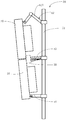
- FIG. 1 is a schematic view showing the internal side structure of an antenna according to a first embodiment of the present invention.
- FIG. 2 is a schematic diagram showing another connection manner of the first antenna portion and the second antenna portion of the antenna shown in FIG. 1.
- FIG. 2 is a schematic diagram showing another connection manner of the first antenna portion and the second antenna portion of the antenna shown in FIG. 1.
- FIG 3 is a schematic view showing the internal side structure of an antenna according to a second embodiment of the present invention.
- FIG. 4 is a schematic view showing the internal side structure of an antenna according to a third embodiment of the present invention.
- FIG. 5 is a front elevational view of the first reflector of the antenna shown in FIG. 4.
- FIG. 5 is a front elevational view of the first reflector of the antenna shown in FIG. 4.
- Fig. 6 is a schematic view showing the internal side structure of an antenna according to a fourth embodiment of the present invention.
- FIG. 7 is a schematic illustration of the antenna assembly of the present invention.
- Figure 8 is a schematic view showing the combined structure of the connecting member and the connecting arm of the antenna of the present invention.
- Embodiments of the present invention provide an antenna and a base station having the antenna.
- the base station may be a terminal network service site.
- An antenna according to an embodiment of the present invention includes: a first antenna portion and a second antenna portion, wherein the first antenna portion includes a first radome and is disposed in the first radome a first reflector; the second antenna cover includes a second radome and a second reflector disposed in the second radome, the first radome being detachably coupled to the second radome,
- the working surface of the first reflecting plate is coplanar with the working surface of the second reflecting plate; the plurality of antenna elements of the working surface of the first reflecting plate and the plurality of antennas on the working surface of the second reflecting plate
- the array is used to construct different kinds of antennas according to the frequency band and the number of transceiver channels configured by the antenna.
- the antenna array on the first reflector and the antenna array on the second reflector are used to jointly construct a first type antenna; or the antenna array on the first reflector is used to construct a second A type antenna, the antenna element of the second reflector is used to construct a third type of antenna.
- the antenna of this embodiment has two or types of antenna performances.
- the first type of antenna may be a low frequency antenna, and the second type antenna and the third type antenna are high frequency antennas, which may be the same or different frequency bands, and the second type antenna and the first type
- the three types of antennas can exist independently of each other. Or the first type of antenna, the second type of antenna, and the third type of antenna have their own operations at the same time.
- a part of the antenna elements on the first reflector and a part of the antennas of the second reflector are used to jointly construct a first type of antenna, and another part of the antenna of the first reflector Another portion of the antenna array of the two reflectors is used to construct the second type antenna and the third type antenna, respectively.
- a part of the antenna elements on the first reflector and a plurality of antenna elements of the second reflector are used to jointly construct a first type of antenna, and another part of the antenna of the first reflector is used to construct a second Type antenna.
- the first antenna portion and the second antenna portion are independently disposed, and at least two types of frequency band antenna modules can be implemented and one antenna module (antenna type) can be replaced at any time and combined with another antenna module to form a new antenna.
- the entire antenna and the enhanced modular combination adaptation station can be diversified, the antenna design complexity is reduced, and manufacturability is improved. And the other half of the module can be used to protect the value of the customer's investment.
- the antenna includes a first antenna portion 10 and a second antenna that is detachably connected to the first antenna portion 10 .
- Department 20 The first antenna portion 10 includes a first radome 11 and a first reflector 12 disposed in the first radome 11; the second antenna portion 20 includes a second radome 21 and is disposed on the second radome 21 a second reflector 22, specifically, the first radome 11 is detachably connected to the first radome 21, such that the working surface 121 of the first reflector 12 and the second reflector The working face 221 of 22 remains coplanar.
- a plurality of antenna arrays arranged in a row are disposed on the working surface 121 of the first reflecting plate 12 and the working surface 221 of the second reflecting plate 22.
- the first radome 11 and the second radome 21 may be transparent covers of the box structure, and the array reflectors constituting the antenna are received therein, and the RF module adapted to the antenna may be carried, and the RF port of the antenna may be set.
- the first radome 11 and the second radome 21 may also be groove-shaped transparent covers that are engaged with the RF module assembly of the antenna to form a box structure as a complete radome, to accommodate the reflector and the antenna of the antenna, and The RF port can be directly placed on the RF module assembly.
- the first radome 11 and the second radome 21 are taken as an example.
- the reflector, the antenna array, the RF port, the phase shifter and the like are disposed in the radome.
- the detachable connection of the first antenna portion 10 and the second antenna portion 20 specifically connects the first radome 11 and the second radome 21 via a connecting member.
- the size of the first radome 11 and the second radome 22 are at least the same in the width dimension.
- the length dimension is also the same, which can be understood as two antennas of exactly the same size.
- the first radome 11 and the second radome 21 are arranged in the longitudinal direction, so that the antenna as a whole can be neat and tidy, has an integrated aesthetic effect, and can fully utilize the base station when installed on the base station. space.
- the gap error between the first radome 11 and the second radome 21 is less than or equal to 5 mm to ensure that the antenna ray as the first type antenna can be equally spaced within the minimum error.
- the transparent cover of the radome is a groove-like structure and the RF module assembly is combined, and the first radome 11 and the second radome 22 are the same size at least in the width dimension, and the length dimension is also identical.
- the first reflector 12 is detachably mounted in the first radome 11, and the second reflector 22 is detachably slidably mounted in the second radome 21;
- the sliding mode can be realized by the simplest method of matching the reflecting plate and the sliding slot.
- the antenna includes a connecting member 30 fixedly connected to the back of the first radome 11 and the back of the second radome 21 and located at a position where the first radome 11 and the second radome 12 are connected So that the working surface 121 of the first reflecting plate 12 and the working surface 221 of the second reflecting plate 22 are always coplanar, that is, kept in the same plane.
- the connecting member 30 may be a suction cup structure locked between the first radome 11 and the second radome 12, a handle or a connecting rod connecting the first radome 11 and the second radome 12, and the like.
- the end of the connecting member 30 is provided with a roller for connecting with a pole supporting the antenna.
- the connector 30 can be detached from the first radome 11 or the second radome 12 alone to replace the first antenna portion 10 or the second antenna portion 20.
- the connecting member 30 is provided with a fastener, and the fastener pressing connector 30 is fixed to the first antenna.
- the cover 11 and the two portions of the second radome 12 connect the first radome 11 and the second radome 12 more closely.
- the connecting member 30 includes a base body (not shown) provided with a roller 32 , and the first fixing a portion 33, a second fixing portion 34, and a fastener 35 connecting the first fixing portion 33 and the second fixing portion 34, wherein the first fixing portion 33 and the second fixing portion 34 are respectively connected to opposite sides of the base body,
- the fastener 35 locks the first fixing portion 33 and the second fixing portion 34 toward the base body through the base body, the first fixing portion 33, and the second fixing portion 34.
- the ends of the first fixing portion 33 and the second fixing portion 34 are respectively provided with connecting plates 36 for fixed connection with the first radome 11 and the second radome 21.
- the antenna array on the first reflector 12 and the second reflector 22 is the first antenna of the first type jointly constructed by the first antenna portion 10 and the second antenna portion 20.
- the antenna array A that is, the first antenna portion 10 and the second antenna portion 20, jointly constructs the antenna, and the number of the plurality of antenna arrays is arranged in accordance with the frequency band and the number of transmission and reception channels configured by the antenna in the present embodiment.
- the first type of antenna includes a first radio frequency module 45 disposed on a back of the first radome 11 facing away from the radiation direction of the antenna, and the first radio frequency module 45 and the first radio frequency of the first type antenna
- the port 44 is a jumper connection, or the first radio frequency module 45 is connected to the first radio frequency port 44 of the first type antenna through a connector to adapt the connection of the radio frequency modules of different transceiver channels.
- the first radio frequency module 45 is configured to implement a transceiving signal of the first antenna element A through the first radio frequency port 44, wherein the signal beam down-tilt angle is adjusted by the phase shifter.
- the first antenna element A of the first type of antenna is set according to the frequency band of the first radio frequency module 45 and the number of transceiver channels configured by the antenna.
- the first antenna element A is arranged in a line at equal intervals between the first reflector 12 and the second reflector 22 in the direction of the second reflector 22 toward the second reflector 22 .
- a column length dimension of a portion of the first antenna element on the first reflector is the same as a column length dimension of another portion of the first antenna element on the second reflector, and the second arrangement facilitates antenna design and Craftsmanship.
- a phase shifter 43 of the first type antenna is disposed in the first radome 11 , and the first antenna element A is electrically connected to the first radome 11 through the phase shifter 43 .
- the first RF port 44 is disposed in the first radome 11 , and the first antenna element A is electrically connected to the first radome 11 through the phase shifter 43 .
- the lengths of the first antenna portion 10 and the second antenna portion 20 may not be equal, that is, the lengths of the first radome and the second radome are not equal, the first reflector 12 and the second
- the column lengths of the antenna elements on the reflector 22 may also be unequal.
- the first type antenna is a low frequency antenna
- the first antenna element A is a low frequency antenna array
- the radio frequency is 1710-2610 GHZ.
- the size of the first antenna element A is inversely proportional to its radio frequency.
- the first radome 11 and the second radome 21 have a length sum of 2 m, and the first radome 11 and the second radome 21 have a length of 1 m. In other embodiments, the first radome 11 and the second radome 21 have a length of 1.3 m.
- the first antenna element A is eight, and is evenly distributed on the first reflector 12 and the second reflector 22. The traces of each two antenna arrays are merged into a branch line and phase shift through the PCB.
- the antenna interface needs to be upgraded, for example, if the number of antenna elements A is increased and the antenna of 2 m is replaced with 2.6 m, the entire antenna does not need to be discarded, and only the first antenna portion 10 or the second antenna portion 20 needs to be replaced, or even only The replacement of the first reflector or the second reflector can be performed, and the operation is simple and cost-saving.
- the first radome 11 is provided with a blind plug male 111
- the second radome 21 is provided with a blind plug female 211
- the blind plug male 111 and the blind plug female 211 The electrical connection between the first antenna element A located on the second reflector 12 and the phase shifter 43 is implemented, and the manner of the blind plug interconnection is relatively simple.
- the first antenna element A on the second reflecting plate 22 and the phase shifter 43 are connected by a jumper 46, and when the number of the jumpers 46 is plural, the jump The length of the line is the same.
- the branch line connecting the plurality of first antenna elements A is concentrated by a division of labor to a branch line and then electrically connected to the phase shifter 43 through a jumper, and the connection mode is simple.
- the antenna array on the first reflector 12 and the antenna array on the second reflector 22 are respectively a second antenna element B of a second type antenna and a third antenna element C of a third type antenna, which are independently formed by one antenna portion 10 and the second antenna portion 20, that is, the first antenna portion 10 and the second antenna portion
- the second type antenna and the third type antenna are respectively constructed, and the second type antenna and the third type antenna can operate independently or together.
- the antenna array as the second antenna element B is set according to the frequency band and the number of transmission and reception channels of the configured radio frequency module of the second type antenna.
- the antenna array as the third antenna element C is a plurality of different antennas set according to the frequency band and the number of transmission and reception channels of the configured RF module of the third type antenna, and is respectively set in the first reflection.
- the board 12 and the second reflector 22 are different in frequency of the first antenna element A and the second antenna element B.
- the second antenna element B is a high-band antenna array.
- the number and arrangement of the second antenna element B on the first reflector 12 and the third antenna frame C on the second reflector 22 may be the same or different to adapt to different multi-dimensional radio frequency adjustments. .
- the size of the second antenna element is inversely proportional to its radio frequency.
- the frequency of the second antenna element B and the third antenna element C can be set according to actual needs.
- the second antenna of the first antenna unit 10 is in the 8T8R mode
- the third antenna of the second antenna 20 is in the 4T4R mode or the 8T8R mode, and may also be the 32T32R mode.
- the second type antenna includes a feed network electrically connecting a plurality of the second antenna elements B in a suspended strip line structure, and the feed network is connected to a second radio frequency on a radome corresponding to the second type antenna port.
- the feed network includes a division module and a phase shift module, and the division module connects the corresponding second type antenna array and the phase shift module, and the division module sets a port corresponding to the second antenna array or
- the port of the two antenna array branch line is used to realize the connection between the second antenna element B and the phase shifting module, and the phase shifting module adjusts the phase of the signal wave.
- the second antenna of the first antenna unit 10 includes a feed network 16 disposed in the first radome 11 and a radio frequency port on the first radome 11 connected to the feed network 16. 17.
- the third type antenna includes a feed network electrically connecting a plurality of the third antenna elements C in a suspended strip line structure, and the feed network is connected to a second radio frequency on a radome corresponding to the third type antenna port.
- the feed network includes a division module and a phase shift module, and the division module connects the corresponding third antenna antenna array and the phase shift module, and the division module sets a port corresponding to the third antenna array or
- the port of the third antenna array branch line is used to realize the connection between the third antenna element C and the phase shifting module, and the phase shifting module adjusts the phase of the signal wave.
- the second antenna of the second antenna unit 20 includes a feed network 26 disposed in the second radome 21 and a second antenna cover 21 connected to the feed network 26.
- the second type antenna and the third type antenna are high frequency antennas, and the antenna array of the high frequency band antenna compensates for insufficient column length of the antenna array in the high frequency band by the suspended strip line structure feeding network, and the antenna array frequency is lowered. Ensure the performance of the low frequency band antenna and the high frequency band antenna.
- the second type antenna includes a second radio frequency module disposed on a back of the first radome facing away from the radiation direction of the antenna, and the second radio frequency module is connected to the radio frequency port of the second type antenna by a jumper. Or the second radio frequency module is connected to the radio frequency port of the second type antenna through a connector.
- the second type antenna configured by the first antenna portion 10 includes a second radio frequency module 18 disposed on the back of the first radome 11 facing away from the radiation direction of the antenna.
- the third type antenna constructed by the second antenna portion 20 includes a second radio frequency module 28 disposed on the back of the second radome 21 facing away from the radiation direction of the antenna.
- the corresponding radio frequency port of the radio frequency module is a jumper connection (not shown), and the radio frequency module transmits the signal to the feed network through the radio frequency port, and the post-path division module adjusts the post-path division module to transmit to each antenna array radiation. Go out.
- the antenna of the embodiment includes two sets of independent second type antennas and third type antennas of the same or different module architectures that can be easily replaced, and can respectively adapt to different RF module requirements of different transceiver channels, and enhance multi-dimensional adjustment of the antenna.
- the enhanced modular combination adaptation site is versatile, reducing the variety of accessories such as antennas and phase shifters, and each sub-antenna can be independently maintained.
- a part of the antenna elements on the first reflecting plate and the plurality of antenna elements of the second reflecting plate are jointly constructed as a first
- the type antenna that is, the partial antenna element on the first reflecting plate 12 and the antenna element of the second reflecting plate 22 are the first antenna element A of the first type antenna constructed together
- the first reflecting plate 12 The upper antenna array is used as the second antenna element B of the second type antenna. That is, the antenna array on the first reflector 12 and the antenna array on the second reflector 22 are set according to the frequency band and the number of transceiver channels of the radio frequency module configured by the antenna of the first type in this embodiment.
- the antenna element of the second antenna element B is set according to the frequency band of the radio frequency module and the number of transmission and reception channels configured by the second type antenna.
- the plurality of antenna elements of the first reflector 12 are two types of antenna arrays and are arranged in a respective form.
- the plurality of antenna elements of the second reflector 22 are formed in the same manner as a part of the antenna array of the first reflector 12.
- the antenna of this embodiment includes the first type antenna and the second type antenna.
- a second type antenna composed of a partial antenna array on the first reflector 12 includes a feed network 160 disposed in the first radome 11 and a first connection to the feed network 160.
- the second radio frequency port 170 and the second radio frequency module 180 in this embodiment are connected by a jumper.
- the phase shifter 430 of the first type antenna is disposed in the first radome 11 and connected to the first antenna element A, and the phase shifter 430 is connected to the radio frequency port 440 on the first radome 11 Port 440 is coupled to a radio frequency module 450 that is matched to the first type of antenna.
- the first type of antenna is a low frequency antenna which may be active or passive.
- the second type of antenna is a high frequency antenna and can be either active or passive.
- the first antenna element A and the second antenna element B are evenly arranged along the length direction of the first reflector 12 and the second reflector 22; the first reflector 12 is simultaneously disposed.
- the spacing between the two adjacent second antenna elements B is between two adjacent first antenna elements A. Half of the spacing to meet the needs of the spacing between the high frequency antenna and the low frequency antenna array.
- a portion of the antenna array and the second reflector on the first reflector are based on the third embodiment.
- Part of the antenna array is used to jointly construct the first type of antenna, and another part of the antenna element of the first reflector and another part of the antenna of the second reflector are used to construct the second type antenna and the third type antenna, respectively.
- the type antenna and the third type antenna may have frequency band differences, and are high frequency antennas of different frequency bands, and may of course be the same frequency band.
- the plurality of antenna elements of the first reflecting plate 12 are two types of antenna elements and are arranged in respective forms
- the plurality of antenna elements of the second reflecting plate 22 are two types of antenna elements and arranged in respective forms.
- the partial antenna elements of the same type on the working surface of the first reflecting plate 12 and the working surface of the second reflecting plate 22 are collectively the first antenna element A of the first type of antenna, and the first reflecting plate 12
- the partial antenna elements of the same type on the working surface are collectively the second antenna element B of the second type antenna
- the partial antenna elements on the working surface of the second reflection plate 22 are the third antenna elements C of the third type antenna.
- the second type of antenna includes a radio frequency port 170 to which the feed network 160 and the feed network 160 are connected, and a radio frequency module 180 to which the radio frequency port 170 is connected.
- Second type The antenna includes a feed port 260 and a radio frequency port 270 connected to the feed network 260 and a radio frequency module 280 connected to the radio frequency port 270.
- the present invention further provides an antenna assembly including the antenna and the antenna pole 50, the antenna including the connecting member 30, and the connecting member 30 fixedly connecting the first radome 11
- the back of the back and the back of the second radome 21 are located at the end positions of the space so that the working faces of the first reflecting plate 12 and the second reflecting plate 22 are always coplanar.
- the antenna performance of the first type of antenna described above can be guaranteed.
- the antenna pole 50 includes a rod body 51 and an adjustment arm 52, a connecting arm 53 and a support arm 54 fixed to the rod body 51 in the axial direction along the rod body 51, and the adjustment arm 52 is connected to the second body.
- the radome 21 is away from the end of the connecting arm 53, and the supporting arm 54 is connected to an end of the first radome 11 away from the connecting arm 53 to support the first antenna portion 10 and the second antenna a portion 20, the telescopic expansion of the adjustment arm 52 to achieve simultaneous adjustment of the inclination angle of the first antenna portion 10 and the second antenna portion 20, the connection arm 53 adjustably connecting the connector 30 to enable the The one antenna portion 10 and the second antenna portion 20 are always kept in synchronization.
- the antenna is fixed to the pole by three mounting points of the adjusting arm 52, the connecting arm 53 to which the connecting member is connected, and the supporting arm 54 to achieve stable balance and to separately split the first antenna portion and the second antenna portion.
- the adjusting arm 52 includes two arm bodies 521 that are rotatably connected by a rotating shaft.
- the free end of one arm body 521 is detachably fixed to the holding rod 51, and the free end of the other arm body 521 can be The detachment is fixed to the back end of the second radome 21.
- the two arm bodies 521 are elongated and shortened by relative rotation of the rotating shaft.
- One end of the support arm 54 is detachably fixed to the pole 51, and the other end is detachably fixed to an end of the first radome 11 away from the second radome 21, and the support arm 54 is adjusted.
- the second radome 21 is moved with an angle, for example, the support arm 54 and the first radome 11 are locked by a rotating shaft and a nut.
- the angle of the first radome 11 can be fixed by a manual adjustment nut.
- the connecting arm 53 includes a connecting body 531 fixed to the pole 51.
- the connecting body 531 is provided with an inclined sliding slot 532, and the roller 32 of the connecting member 30 is mounted on the connecting body 530.
- the sliding groove 532 is slid or locked in the sliding groove 532, and can be locked by a nut.
- the adjustment of the angles of the first antenna portion 10 and the second antenna portion 20 with the adjustment arm 52 is achieved by adjusting the position of the roller of the connecting member 30 in the sliding groove 532.
- the connecting arm 53 further includes a latching frame 533.
- the connecting body 531 is a frame structure, and includes two extending plates and a connecting plate 5312 connecting the two extending plates 5311.
- the extending plate 5311 is provided with the sliding slot 532.
- the latch 533 is bolted to the connecting plate 5312 to be clamped on the pole.
- the present invention also provides a base station comprising a base station bracket and the antenna assembly, the poles being detachably fixed to the base station bracket at different angles.
- the base station is assembled by stacking two modules through the antenna on the antenna component, and can be adapted to configure antennas with different frequency bands of different frequency bands without replacing a large number of antennas as a whole, and as long as implemented in a pole, the station pole is reduced. The need to save base station space and maintenance costs.
Landscapes
- Engineering & Computer Science (AREA)
- Computer Networks & Wireless Communication (AREA)
- Physics & Mathematics (AREA)
- Electromagnetism (AREA)
- Variable-Direction Aerials And Aerial Arrays (AREA)
- Aerials With Secondary Devices (AREA)
Abstract
Priority Applications (7)
| Application Number | Priority Date | Filing Date | Title |
|---|---|---|---|
| EP23168695.7A EP4270658A3 (fr) | 2017-10-30 | 2017-10-30 | Antenne, ensemble antenne et station de base |
| CN202111298798.9A CN114171913A (zh) | 2017-10-30 | 2017-10-30 | 天线、天线组件及基站 |
| PCT/CN2017/108366 WO2019084720A1 (fr) | 2017-10-30 | 2017-10-30 | Antenne, ensemble antenne et station de base |
| BR112020008581-2A BR112020008581B1 (pt) | 2017-10-30 | Antena, conjunto de antena, e estação base | |
| CN201780093923.8A CN111066200B (zh) | 2017-10-30 | 2017-10-30 | 天线、天线组件及基站 |
| EP17931061.0A EP3691032B1 (fr) | 2017-10-30 | 2017-10-30 | Antenne, ensemble antenne et station de base |
| US16/861,425 US11316257B2 (en) | 2017-10-30 | 2020-04-29 | Antenna, antenna assembly, and base station |
Applications Claiming Priority (1)
| Application Number | Priority Date | Filing Date | Title |
|---|---|---|---|
| PCT/CN2017/108366 WO2019084720A1 (fr) | 2017-10-30 | 2017-10-30 | Antenne, ensemble antenne et station de base |
Related Child Applications (1)
| Application Number | Title | Priority Date | Filing Date |
|---|---|---|---|
| US16/861,425 Continuation US11316257B2 (en) | 2017-10-30 | 2020-04-29 | Antenna, antenna assembly, and base station |
Publications (1)
| Publication Number | Publication Date |
|---|---|
| WO2019084720A1 true WO2019084720A1 (fr) | 2019-05-09 |
Family
ID=66333410
Family Applications (1)
| Application Number | Title | Priority Date | Filing Date |
|---|---|---|---|
| PCT/CN2017/108366 Ceased WO2019084720A1 (fr) | 2017-10-30 | 2017-10-30 | Antenne, ensemble antenne et station de base |
Country Status (4)
| Country | Link |
|---|---|
| US (1) | US11316257B2 (fr) |
| EP (2) | EP3691032B1 (fr) |
| CN (2) | CN111066200B (fr) |
| WO (1) | WO2019084720A1 (fr) |
Cited By (5)
| Publication number | Priority date | Publication date | Assignee | Title |
|---|---|---|---|---|
| CN112397886A (zh) * | 2020-11-06 | 2021-02-23 | 康威通信技术股份有限公司 | 一种窄波束定向天线及其制备方法 |
| EP3840117A1 (fr) * | 2019-12-18 | 2021-06-23 | CommScope Technologies LLC | Unités d'antenne de station de base dotées de réseaux ayant de multiples antennes qui sont connectées par des câbles volants |
| CN113708087A (zh) * | 2021-08-30 | 2021-11-26 | 中信科移动通信技术股份有限公司 | 融合天线 |
| EP4047749A4 (fr) * | 2019-11-30 | 2022-11-02 | Huawei Technologies Co., Ltd. | Système d'antennes et station de base |
| WO2023109765A1 (fr) * | 2021-12-16 | 2023-06-22 | 华为技术有限公司 | Système d'antenne et dispositif de communication |
Families Citing this family (18)
| Publication number | Priority date | Publication date | Assignee | Title |
|---|---|---|---|---|
| CN211238513U (zh) * | 2019-12-18 | 2020-08-11 | 康普技术有限责任公司 | 多天线安装装置以及多天线组件 |
| US11532884B1 (en) * | 2020-03-16 | 2022-12-20 | Amazon Technologies, Inc. | Interleaved phased array antennas |
| CN211829184U (zh) * | 2020-05-21 | 2020-10-30 | 康普技术有限责任公司 | 天线安装装置和基站天线系统 |
| US12327930B2 (en) * | 2020-09-29 | 2025-06-10 | T-Mobile Usa, Inc. | Multi-band millimeter wave (MMW) antenna arrays |
| CN213460078U (zh) * | 2020-12-21 | 2021-06-15 | 康普技术有限责任公司 | 基站天线和用于基站天线的板组件 |
| EP4262021B1 (fr) * | 2020-12-31 | 2025-11-26 | Huawei Technologies Co., Ltd. | Module d'antenne et système de station de base |
| CN115458942A (zh) * | 2021-06-08 | 2022-12-09 | 康普技术有限责任公司 | 用于天线总成的天线安装装置和天线系统 |
| WO2022265904A1 (fr) | 2021-06-16 | 2022-12-22 | Commscope Technologies Llc | Antennes de station de base comprenant un module d'antenne active, dispositifs et procédés associés |
| CN113258263B (zh) * | 2021-07-15 | 2021-11-02 | 中兴通讯股份有限公司 | 基站设备 |
| CN117999702A (zh) | 2021-09-22 | 2024-05-07 | 康普技术有限责任公司 | 具有有源天线模块的基站天线以及相关安装系统和方法 |
| CN116111343A (zh) * | 2021-11-11 | 2023-05-12 | 华为技术有限公司 | 馈电网络、天线装置及通信设备 |
| CN116264346A (zh) * | 2021-12-14 | 2023-06-16 | 华为技术有限公司 | 一种天线系统及基站天馈系统 |
| CN119278546A (zh) * | 2022-01-25 | 2025-01-07 | 株式会社Kmw | 小小区基站天线装置 |
| CN118198705A (zh) * | 2022-12-12 | 2024-06-14 | 宏达国际电子股份有限公司 | 天线基座与天线组 |
| CN118198721A (zh) * | 2022-12-14 | 2024-06-14 | 上海华为技术有限公司 | 天线、天线组件和基站 |
| CN116565508A (zh) * | 2023-05-12 | 2023-08-08 | 广东通宇通讯股份有限公司 | 一种新型高增益双拼级联式天线构架 |
| US20250141099A1 (en) * | 2023-10-30 | 2025-05-01 | Hewlett Packard Enterprise Development Lp | Radio frequency connection structure |
| CN120728231A (zh) * | 2024-03-30 | 2025-09-30 | 华为技术有限公司 | 一种天线罩组件、天线及基站 |
Citations (7)
| Publication number | Priority date | Publication date | Assignee | Title |
|---|---|---|---|---|
| CN2641843Y (zh) * | 2003-09-04 | 2004-09-15 | 上海大学 | 车载电话用双频共面振子天线 |
| US20060077102A1 (en) * | 2004-07-23 | 2006-04-13 | Farrokh Mohamadi | Wafer scale beam forming antenna module with distributed amplification |
| US20080030416A1 (en) * | 2006-08-04 | 2008-02-07 | Raytheon Company | Dual band space-fed array |
| CN102522634A (zh) * | 2011-12-13 | 2012-06-27 | 华为技术有限公司 | 天线装置、基站及通信系统 |
| CN102714345A (zh) * | 2012-03-09 | 2012-10-03 | 华为技术有限公司 | 天线系统、基站和通信系统 |
| CN205029023U (zh) * | 2015-10-21 | 2016-02-10 | 深圳市安拓浦科技有限公司 | 一种小型集成天线基站 |
| CN105790860A (zh) * | 2014-12-25 | 2016-07-20 | 中兴通讯股份有限公司 | 天线耦合校准系统 |
Family Cites Families (11)
| Publication number | Priority date | Publication date | Assignee | Title |
|---|---|---|---|---|
| US7639196B2 (en) * | 2001-07-10 | 2009-12-29 | Andrew Llc | Cellular antenna and systems and methods therefor |
| CN102308437B (zh) * | 2009-05-26 | 2013-09-11 | 华为技术有限公司 | 一种天线装置 |
| US20120128040A1 (en) * | 2010-11-23 | 2012-05-24 | Peter Kenington | Module for an Active Antenna System |
| CN201946739U (zh) * | 2010-12-23 | 2011-08-24 | 中国移动通信集团设计院有限公司 | 一种共站址基站天线 |
| US9979078B2 (en) * | 2012-10-25 | 2018-05-22 | Pulse Finland Oy | Modular cell antenna apparatus and methods |
| CN102983387B (zh) * | 2012-12-10 | 2015-04-15 | 华为技术有限公司 | 一种天线安装件 |
| CN103633452B (zh) * | 2013-11-28 | 2016-09-28 | 华为技术有限公司 | 一种天线及无线信号发送、接收方法 |
| KR102074918B1 (ko) * | 2014-02-04 | 2020-03-02 | 삼성전자주식회사 | 가변적인 기지국 안테나 장치 |
| US20160099505A1 (en) * | 2014-10-03 | 2016-04-07 | Nokia Solutions And Networks Oy | Modular active antenna structures and arrangements |
| WO2017008264A1 (fr) * | 2015-07-15 | 2017-01-19 | 华为技术有限公司 | Antenne, système d'antenne et station de base |
| CN114171934B (zh) * | 2017-01-24 | 2025-10-17 | 户外无线网络有限公司 | 基站天线单元及用于安装基站天线单元的方法 |
-
2017
- 2017-10-30 WO PCT/CN2017/108366 patent/WO2019084720A1/fr not_active Ceased
- 2017-10-30 CN CN201780093923.8A patent/CN111066200B/zh active Active
- 2017-10-30 CN CN202111298798.9A patent/CN114171913A/zh active Pending
- 2017-10-30 EP EP17931061.0A patent/EP3691032B1/fr active Active
- 2017-10-30 EP EP23168695.7A patent/EP4270658A3/fr active Pending
-
2020
- 2020-04-29 US US16/861,425 patent/US11316257B2/en active Active
Patent Citations (7)
| Publication number | Priority date | Publication date | Assignee | Title |
|---|---|---|---|---|
| CN2641843Y (zh) * | 2003-09-04 | 2004-09-15 | 上海大学 | 车载电话用双频共面振子天线 |
| US20060077102A1 (en) * | 2004-07-23 | 2006-04-13 | Farrokh Mohamadi | Wafer scale beam forming antenna module with distributed amplification |
| US20080030416A1 (en) * | 2006-08-04 | 2008-02-07 | Raytheon Company | Dual band space-fed array |
| CN102522634A (zh) * | 2011-12-13 | 2012-06-27 | 华为技术有限公司 | 天线装置、基站及通信系统 |
| CN102714345A (zh) * | 2012-03-09 | 2012-10-03 | 华为技术有限公司 | 天线系统、基站和通信系统 |
| CN105790860A (zh) * | 2014-12-25 | 2016-07-20 | 中兴通讯股份有限公司 | 天线耦合校准系统 |
| CN205029023U (zh) * | 2015-10-21 | 2016-02-10 | 深圳市安拓浦科技有限公司 | 一种小型集成天线基站 |
Cited By (11)
| Publication number | Priority date | Publication date | Assignee | Title |
|---|---|---|---|---|
| EP4047749A4 (fr) * | 2019-11-30 | 2022-11-02 | Huawei Technologies Co., Ltd. | Système d'antennes et station de base |
| CN120184592A (zh) * | 2019-11-30 | 2025-06-20 | 华为技术有限公司 | 一种天线系统及基站 |
| EP3840117A1 (fr) * | 2019-12-18 | 2021-06-23 | CommScope Technologies LLC | Unités d'antenne de station de base dotées de réseaux ayant de multiples antennes qui sont connectées par des câbles volants |
| CN114830436A (zh) * | 2019-12-18 | 2022-07-29 | 康普技术有限责任公司 | 具有跨越由跳线电缆连接的多个天线的阵列的基站天线单元 |
| US11589418B2 (en) | 2019-12-18 | 2023-02-21 | Commscope Technologies Llc | Base station antenna units having arrays spanning multiple antennas that are connected by jumper cables |
| US12101853B2 (en) | 2019-12-18 | 2024-09-24 | Outdoor Wireless Networks LLC | Base station antenna units having arrays spanning multiple antennas that are connected by jumper cables |
| CN114830436B (zh) * | 2019-12-18 | 2026-01-06 | 户外无线网络有限公司 | 具有跨越由跳线电缆连接的多个天线的阵列的基站天线单元 |
| CN112397886A (zh) * | 2020-11-06 | 2021-02-23 | 康威通信技术股份有限公司 | 一种窄波束定向天线及其制备方法 |
| CN112397886B (zh) * | 2020-11-06 | 2022-12-16 | 康威通信技术股份有限公司 | 一种窄波束定向天线及其制备方法 |
| CN113708087A (zh) * | 2021-08-30 | 2021-11-26 | 中信科移动通信技术股份有限公司 | 融合天线 |
| WO2023109765A1 (fr) * | 2021-12-16 | 2023-06-22 | 华为技术有限公司 | Système d'antenne et dispositif de communication |
Also Published As
| Publication number | Publication date |
|---|---|
| CN111066200B (zh) | 2021-11-19 |
| CN111066200A (zh) | 2020-04-24 |
| EP3691032A4 (fr) | 2020-10-07 |
| EP3691032A1 (fr) | 2020-08-05 |
| EP3691032B1 (fr) | 2023-05-24 |
| CN114171913A (zh) | 2022-03-11 |
| BR112020008581A2 (pt) | 2020-10-20 |
| EP4270658A3 (fr) | 2024-02-07 |
| EP4270658A2 (fr) | 2023-11-01 |
| US11316257B2 (en) | 2022-04-26 |
| US20200259248A1 (en) | 2020-08-13 |
Similar Documents
| Publication | Publication Date | Title |
|---|---|---|
| WO2019084720A1 (fr) | Antenne, ensemble antenne et station de base | |
| CN111092296B (zh) | 基站天线及其辐射单元 | |
| US11652300B2 (en) | Radiating elements having angled feed stalks and base station antennas including same | |
| US20240332785A1 (en) | Base station antennas having an active antenna module and related devices and methods | |
| CN111786081B (zh) | 具有集成阵列的多频带基站天线 | |
| US10847902B2 (en) | Enhanced phase shifter circuit to reduce RF cables | |
| KR101609665B1 (ko) | 이동통신 기지국 안테나 | |
| US7755559B2 (en) | Dual-band omnidirectional antenna | |
| TWI628861B (zh) | 複合天線 | |
| CN205543221U (zh) | 一种独立可调双频双极化基站天线 | |
| KR101798628B1 (ko) | 기지국용 배열 안테나 | |
| CN113285225A (zh) | 宽带天线、多频带天线单元以及天线阵列 | |
| CN107251318A (zh) | 多频段辐射元件 | |
| CN110622352A (zh) | 天线、阵列天线、扇形天线以及偶极天线 | |
| CN104995792A (zh) | 一种天线装置以及基站 | |
| EP3794675B1 (fr) | Structure d'antenne multibande | |
| JP2013219723A (ja) | アンテナ装置 | |
| CN113497341A (zh) | 天线组件和基站天线 | |
| US20210336355A1 (en) | Co-located antennas with coupled arms | |
| CN102738566A (zh) | 一种小型化三频卫星通信天线 | |
| KR100973489B1 (ko) | 빔 지향각도가 조절되는 내장형 안테나 | |
| CN107845854A (zh) | 复合天线 | |
| CN203760678U (zh) | 多频带天线 | |
| BR112020008581B1 (pt) | Antena, conjunto de antena, e estação base | |
| KR20150011939A (ko) | 이중편파 방사소자어셈블리 및 이를 구비한 이중편파 안테나 |
Legal Events
| Date | Code | Title | Description |
|---|---|---|---|
| 121 | Ep: the epo has been informed by wipo that ep was designated in this application |
Ref document number: 17931061 Country of ref document: EP Kind code of ref document: A1 |
|
| NENP | Non-entry into the national phase |
Ref country code: DE |
|
| ENP | Entry into the national phase |
Ref document number: 2017931061 Country of ref document: EP Effective date: 20200429 |
|
| REG | Reference to national code |
Ref country code: BR Ref legal event code: B01A Ref document number: 112020008581 Country of ref document: BR |
|
| ENP | Entry into the national phase |
Ref document number: 112020008581 Country of ref document: BR Kind code of ref document: A2 Effective date: 20200429 |