WO2019087247A1 - Système, procédé, et programme de génération d'images longues - Google Patents
Système, procédé, et programme de génération d'images longues Download PDFInfo
- Publication number
- WO2019087247A1 WO2019087247A1 PCT/JP2017/039121 JP2017039121W WO2019087247A1 WO 2019087247 A1 WO2019087247 A1 WO 2019087247A1 JP 2017039121 W JP2017039121 W JP 2017039121W WO 2019087247 A1 WO2019087247 A1 WO 2019087247A1
- Authority
- WO
- WIPO (PCT)
- Prior art keywords
- image
- images
- imaging device
- long
- generation system
- Prior art date
- Legal status (The legal status is an assumption and is not a legal conclusion. Google has not performed a legal analysis and makes no representation as to the accuracy of the status listed.)
- Ceased
Links
Images


Classifications
-
- H—ELECTRICITY
- H04—ELECTRIC COMMUNICATION TECHNIQUE
- H04N—PICTORIAL COMMUNICATION, e.g. TELEVISION
- H04N5/00—Details of television systems
- H04N5/76—Television signal recording
- H04N5/765—Interface circuits between an apparatus for recording and another apparatus
- H04N5/77—Interface circuits between an apparatus for recording and another apparatus between a recording apparatus and a television camera
-
- H—ELECTRICITY
- H04—ELECTRIC COMMUNICATION TECHNIQUE
- H04N—PICTORIAL COMMUNICATION, e.g. TELEVISION
- H04N23/00—Cameras or camera modules comprising electronic image sensors; Control thereof
- H04N23/60—Control of cameras or camera modules
- H04N23/698—Control of cameras or camera modules for achieving an enlarged field of view, e.g. panoramic image capture
-
- B—PERFORMING OPERATIONS; TRANSPORTING
- B64—AIRCRAFT; AVIATION; COSMONAUTICS
- B64U—UNMANNED AERIAL VEHICLES [UAV]; EQUIPMENT THEREFOR
- B64U50/00—Propulsion; Power supply
- B64U50/10—Propulsion
- B64U50/19—Propulsion using electrically powered motors
-
- G—PHYSICS
- G03—PHOTOGRAPHY; CINEMATOGRAPHY; ANALOGOUS TECHNIQUES USING WAVES OTHER THAN OPTICAL WAVES; ELECTROGRAPHY; HOLOGRAPHY
- G03B—APPARATUS OR ARRANGEMENTS FOR TAKING PHOTOGRAPHS OR FOR PROJECTING OR VIEWING THEM; APPARATUS OR ARRANGEMENTS EMPLOYING ANALOGOUS TECHNIQUES USING WAVES OTHER THAN OPTICAL WAVES; ACCESSORIES THEREFOR
- G03B15/00—Special procedures for taking photographs; Apparatus therefor
-
- G—PHYSICS
- G03—PHOTOGRAPHY; CINEMATOGRAPHY; ANALOGOUS TECHNIQUES USING WAVES OTHER THAN OPTICAL WAVES; ELECTROGRAPHY; HOLOGRAPHY
- G03B—APPARATUS OR ARRANGEMENTS FOR TAKING PHOTOGRAPHS OR FOR PROJECTING OR VIEWING THEM; APPARATUS OR ARRANGEMENTS EMPLOYING ANALOGOUS TECHNIQUES USING WAVES OTHER THAN OPTICAL WAVES; ACCESSORIES THEREFOR
- G03B37/00—Panoramic or wide-screen photography; Photographing extended surfaces, e.g. for surveying; Photographing internal surfaces, e.g. of pipe
-
- H—ELECTRICITY
- H04—ELECTRIC COMMUNICATION TECHNIQUE
- H04N—PICTORIAL COMMUNICATION, e.g. TELEVISION
- H04N5/00—Details of television systems
- H04N5/222—Studio circuitry; Studio devices; Studio equipment
-
- H—ELECTRICITY
- H04—ELECTRIC COMMUNICATION TECHNIQUE
- H04N—PICTORIAL COMMUNICATION, e.g. TELEVISION
- H04N5/00—Details of television systems
- H04N5/76—Television signal recording
-
- B—PERFORMING OPERATIONS; TRANSPORTING
- B64—AIRCRAFT; AVIATION; COSMONAUTICS
- B64D—EQUIPMENT FOR FITTING IN OR TO AIRCRAFT; FLIGHT SUITS; PARACHUTES; ARRANGEMENT OR MOUNTING OF POWER PLANTS OR PROPULSION TRANSMISSIONS IN AIRCRAFT
- B64D47/00—Equipment not otherwise provided for
- B64D47/08—Arrangements of cameras
-
- B—PERFORMING OPERATIONS; TRANSPORTING
- B64—AIRCRAFT; AVIATION; COSMONAUTICS
- B64U—UNMANNED AERIAL VEHICLES [UAV]; EQUIPMENT THEREFOR
- B64U2101/00—UAVs specially adapted for particular uses or applications
- B64U2101/30—UAVs specially adapted for particular uses or applications for imaging, photography or videography
Definitions
- the present invention relates to a long image generation system, method and program.
- a long image including an imaging device, a movable body on which the imaging device is mounted, and a computer, and superimposing end portions of a plurality of images captured by the imaging device to generate one long image Generation systems are known.
- an irradiation unit that applies a pattern of a predetermined pattern to the surface of the object and the surface of the object to which the pattern of the predetermined pattern is added are divided into a plurality of locations.
- An image acquisition system has been proposed which comprises an imaging unit for capturing images (see Patent Document 2). According to the system described in Patent Document 2, it is possible to provide an image acquisition system capable of acquiring a plurality of images that are easy to connect.
- Patent Document 1 captures an omnidirectional panoramic image while hovering the unmanned aerial vehicle at a predetermined position and rotating the image acquisition device about the first axis.
- an unmanned aerial vehicle moves linearly in a certain direction, it is unclear whether continuous long images can be generated if at least how many images are prepared, and many images are unnecessarily prepared.
- the number of images to be prepared may not be sufficient to generate continuous long images.
- Patent Document 2 is premised on irradiating an object with light, and when the imaging unit and the object are separated, the system described in Patent Document 2 may be adopted. Can not.
- the present invention has been made in view of such a demand, and the moving object moves linearly in a predetermined direction, and the moving object and the object to be photographed are separated by a predetermined distance or more.
- An object of the present invention is to provide a system capable of generating continuous long images with acquisition of as few images as possible.
- the present invention provides the following solutions.
- the invention according to the first feature is A long image comprising an imaging device, a movable body mounted with the imaging device, and a computer, and combining a plurality of images captured by the imaging device with movement of the movable body to obtain a long image
- the computer is An image storage unit that acquires and stores a plurality of images at time intervals that change according to the angle of view of the imaging device and the moving speed of the moving object;
- a long image generation unit that combines a plurality of images stored in the image storage unit to generate a long image; To provide an elongated image generation system.
- the image storage means acquires a plurality of images at time intervals that change according to the angle of view of the imaging device mounted on the moving object and the moving speed of the moving object,
- the long image generation means combines a plurality of images stored in the image storage means to generate a long image.
- the time interval for acquiring a plurality of images can be appropriately adjusted according to the angle of view of the imaging device mounted on the moving object and the moving speed of the moving object, so that the moving object is straight in a certain direction. Even if the moving object and the object to be photographed are separated by a predetermined distance or more, continuous long images can be generated by acquiring as few images as possible.
- the invention according to the second feature is the invention according to the first feature,
- the moving body is a flying body,
- the image storage means provides a long image generation system that acquires a plurality of images at time intervals that change according to the angle of view of the imaging device and the moving speed and altitude of the flying object.
- the moving object is a flying object
- the moving object moves linearly in a certain direction
- the flying object and the object to be photographed are separated by a predetermined distance or more.
- continuous long images can be generated by acquiring as few images as possible.
- the invention according to the third feature is the invention according to the first or second feature
- the computer is An information storage unit in which information indicating the relationship between the angle of view of the imaging device and the moving speed of the moving object and the time interval is stored in advance;
- a time interval setting unit configured to set the time interval according to the angle of view of the imaging device and the moving speed of the moving object from the information stored in the information storage unit;
- Shutter updating means for setting the shutter of the imaging device from the closed state to the open state at the time interval set by the time interval setting means, and for setting the shutter from the open state to the closed state again after a predetermined time has elapsed;
- the image storage means provides a long image generation system that acquires and stores a plurality of images obtained each time the shutter is in an open state.
- the shutter can be opened, and the time interval for acquiring a plurality of images can be appropriately adjusted from the information stored in the information storage means.
- the time interval for acquiring a plurality of images can be appropriately adjusted from the information stored in the information storage means.
- the invention according to the fourth feature is the invention according to the first or second feature, and
- the imaging device captures a first image at a first timing, and captures a second image at a second timing after the first timing.
- the computer determines whether or not a front image occupying a predetermined area forward of the movement direction in the first image and a rear image occupying a predetermined area rearward of the movement direction in the second image overlap by a predetermined degree or more Further comprising means, When it is determined by the determination means that the images overlap with each other by a predetermined degree or more, the image storage means cumulatively stores at least the second image, and sets the second image as the first image. Repeat imaging and determination by the determination means, The long image generation system is provided, in which the imaging of the second image and the determination by the determination unit are performed again when the determination unit does not determine that the images overlap with each other by a predetermined degree or more.
- the front image occupying the predetermined area forward of the movement direction in the first image and the rear image occupying the predetermined area backward in the movement direction of the second image overlap by a predetermined degree or more.
- the image is stored in the image storage means.
- a scale image can be suitably generated.
- the present invention even when the moving body linearly moves in a certain direction and the moving body and the object to be photographed are separated by a predetermined distance or more, acquisition of as few images as possible is continuous. It is possible to provide a system capable of generating a long image.
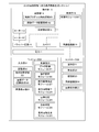
- FIG. 1 is a block diagram showing the hardware configuration and software functions of a long image generation system 1 using a moving object in the first embodiment.
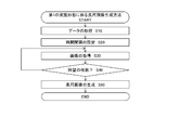
- FIG. 2 is a flowchart showing a method of generating a long image using the long image generation system 1 in the first embodiment.
- FIG. 3 is a chart showing an example of the relationship between the angle of view of the camera, the moving speed and the flying altitude, and the time interval of imaging when the moving object is a flying object.
- FIG. 4 is a block diagram showing a hardware configuration and a software function of a long image generation system 1 'using a moving object in the second embodiment.
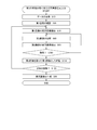
- FIG. 5 is a flowchart showing a method of generating a long image using the long image generation system 1 ′ in the second embodiment.
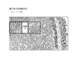
- FIG. 6 is a schematic view showing an algorithm for image acquisition in the second embodiment when the movement direction and the expansion direction of the panoramic image are parallel.
- FIG. 7 is a schematic view showing an algorithm of image acquisition in the second embodiment when the movement direction and the expansion direction of the panoramic image are not parallel.
- FIG. 1 is a block diagram for explaining a hardware configuration and a software function of a long image generation system 1 according to a first embodiment of the present invention.
- the long image generation system 1 is an embodiment of a flying object 10 which is an embodiment of a moving object according to the present invention, and an embodiment of an imaging apparatus according to the present invention, and a camera 17 mounted on the flying object 10
- a controller 20 is connected so as to be capable of wireless communication with the computer 10, and includes a controller 20 for operating the aircraft 10 and a computer 30 for editing an image captured by the camera 17.
- automatic flight control of the flying object 10 is appropriately enabled.
- the controller 20 may be absent.
- the flying object 10 is taken as an example of the moving object, but it may be a moving object moving on the ground.
- the flying object 10 is not particularly limited as long as it is an apparatus capable of capturing an image of an object to be captured from the sky.
- it may be a radio controlled aircraft, a drone called a drone, or may be manned. In the following, it is assumed that the flying object 10 is a drone.
- the flying object 10 includes a rotor 13 for raising and flying the flying object 10, a motor 12 (not shown) for rotating the rotor 13, and a battery 11 (not shown) that functions as a power source for the flying object 10 and supplies power to the motor 12. .
- the flying object 10 is provided with a camera 17 for capturing an image.
- the flying object 10 controls the operation of the flying object 10, the position detecting unit 15 for transmitting positional information of the flying object 10 to the control unit 14, and the motor 12 in accordance with control signals from the control unit 14.
- a driver circuit 16 to be driven, a camera 17 for aerial photographing an object to be photographed according to a control signal from the control unit 14, a control program to be executed by a microcomputer of the control unit 14 and the like are stored in advance
- a storage unit 18 for storing the captured image.
- the flying object 10 includes a wireless communication unit 19 that performs wireless communication with the controller 20.
- main body structure (frame or the like) of a predetermined shape.
- main body structure the same one as a known drone may be employed.
- the battery 11 is a primary battery or a secondary battery, and supplies power to each component in the flying object 10.
- the battery 11 may be fixed to the flying object 10 or may be removable.
- the motor 12 functions as a drive source for rotating the rotor 13 with the power supplied from the battery 11.
- the rotation of the rotor 13 enables the flying object 10 to fly and fly.
- the control unit 14 includes a central processing unit (CPU), a random access memory (RAM), a read only memory (ROM), and the like.
- CPU central processing unit
- RAM random access memory
- ROM read only memory
- control unit 14 realizes the control module 141 by reading a predetermined program.
- the control unit 14 controls the motor 12 to perform flight control (control such as lifting, lowering, horizontal movement, etc.) of the flying object 10. Further, the control unit 14 controls the motor 12 to perform attitude control of the flying object 10 using a gyro (not shown) mounted on the flying object 10.
- flight control control such as lifting, lowering, horizontal movement, etc.
- attitude control of the flying object 10 using a gyro (not shown) mounted on the flying object 10.
- the position detection unit 15 includes LIDAR (Laser Imaging Detection and Ranging) technology and GPS (Global Positioning System) technology. Using the LIDAR technology and the GPS technology in combination, the latitude, longitude, and height of the position where the flying object 10 actually flies is detected.
- LIDAR Laser Imaging Detection and Ranging
- GPS Global Positioning System
- the driver circuit 16 has a function of applying a voltage specified by a control signal from the control unit 14 to the motor 12. Thus, the driver circuit 16 can drive the motor 12 in accordance with the control signal from the control unit 14.
- the camera 17 functions as an imaging device.
- the camera 17 converts (captures) an optical image captured by a lens into an image signal by an imaging device such as a CCD or CMOS.
- the type of camera 17 may be appropriately selected according to the image analysis method of the object to be photographed.
- the storage unit 18 is a device that stores data and files, and includes a data storage unit such as a hard disk, a semiconductor memory, a recording medium, a memory card, and the like.
- the storage unit 18 includes a control program storage area 181 for storing in advance a control program and the like executed by the microcomputer of the control unit 14, and the position detection unit 15 detecting image data captured by the camera 17.
- image data storage area 182 to be stored together with dimensional coordinate data (data of latitude, longitude, and height of a point corresponding to a shooting position of an image shot by the camera 17).
- the image forming the image data may be a still image or a moving image. Also, data stored in the image data storage area can be transferred to the computer 30 through a portable recording medium such as a USB memory or an SD card.
- the wireless communication unit 19 is configured to be capable of wireless communication with the controller 20, and receives a remote control signal from the controller 20.
- the controller 20 has a function of steering the unmanned air vehicle 10.
- the controller 20 stores, in advance, an operation unit 21 used by the user to maneuver the flying object 10, a control unit 22 controlling the operation of the controller 20, and a control program executed by a microcomputer of the control unit 22.
- a wireless communication unit 24 for performing wireless communication with the aircraft 10, and an image display unit 25 for displaying a predetermined image for the user.
- the wireless communication unit 24 is configured to be capable of wireless communication with the airframe 10, and receives a remote control signal toward the airframe 10.
- the image display unit 25 may be integral with a steering device for steering the aircraft 10 or may be separate from the steering device. If it is integral with the control device, the number of devices used by the user can be reduced, and the convenience is enhanced. In the case of being separate from the control device, examples of the image display unit 25 include portable terminal devices such as a smartphone and a tablet terminal that can be wirelessly connected to the wireless communication unit 19 of the flying object 10. In the case of being separate from the control device, even an existing control device without the image display unit 25 has an advantage of being applicable.
- the computer 30 has a function of combining a plurality of images captured by the camera 17 to generate a long image, and a function of setting a shooting timing of the camera 17 for generating a long image.
- the computer 30 stores in advance an input unit 31 for the user to input command information and the like, a control unit 32 for controlling the operation of the computer 30, and a control program to be executed by a microcomputer of the control unit 32 in advance.
- a section 33 and an image display section 34 for displaying a predetermined image to the user.
- the control unit 32 implements a data acquisition module 321, a time interval setting module 322, a shutter update module 323, a number determination module 324, and a long image generation module 325 by reading a predetermined program.
- the time interval setting module 322 is a module for setting a time interval for capturing a plurality of images for generating a long image, and the time interval corresponds to the moving speed of the moving object and the angle of view of the camera 17 Change.
- the storage unit 33 stores an information storage area 331 for storing information on time intervals used by the time interval setting module 322, and a storage of the flying object 10 transferred through a portable recording medium such as a USB memory, an SD card, etc. And an image data storage area 332 for storing the image data stored in the unit 18.
- FIG. 2 is a flowchart showing a method of generating a long image using the long image generation system 1. The respective hardware described above and the processing executed by the software module will be described.
- Step S10 Acquisition of Moving Object Information and Camera Setting Information
- the control unit 32 of the computer 30 of the long image generation system 1 executes the data acquisition module 321 to acquire information on the current moving object and information on the setting value of the camera 17. Specifically, the moving speed of the moving body is acquired as information on the moving body, and the angle of view of the camera 17 is acquired as information on the setting value of the camera 17.
- the flying body is the flying body 10
- the flying height of the flying body 10 is also acquired.
- Step S20 Setting of Time Interval
- the control unit 32 of the computer 30 executes the time interval setting module 322.
- the time interval setting module 322 is executed, the information storage area 331 is read out, and the time interval is set in accordance with the information on the moving object acquired in step S10 and the setting information on the camera 17. Specifically, a predetermined time interval is set according to the moving speed of the moving object and the angle of view of the camera.
- the time interval mentioned here refers to the time interval for obtaining an image by opening the shutter of the camera 17 in the closed state.
- the relationship between the time interval for obtaining an image with the shutter of the camera 17 open and the moving speed of the moving object and the angle of view of the camera is stored in the information storage area 331 in advance. Specifically, the faster the moving speed of the moving object, the shorter the time interval, and the wider the angle of view of the camera, the longer the time interval.
- the time interval stored in the information storage area 331 is read out based on the moving speed of the moving object and the set value of the angle of view of the camera, and is set as the time interval for acquiring an image.
- the relationship between the angle of view of the camera 17, the flight altitude of the flying object 10, the moving speed of the flying object 10, and the time interval for opening the shutter of the camera 17 is in advance stored in the information storage area 331. It is memorized.
- FIG. 3A shows the change of the time interval when the angle of view and the moving speed are fixed and the flying height is changed. As the flight altitude increases, the time interval for opening the shutter increases. This is because the area of the image captured by the camera 17 becomes wider as the flight altitude becomes higher.
- FIG. 3B shows the change of the time interval when the moving angle is changed while the angle of view and the flying height are fixed. As the moving speed increases, the time interval for opening the shutter decreases. This is because the area photographed by the camera 17 moves faster as the moving speed increases.
- FIG. 3C shows the time interval when the flying altitude and the moving speed are the same as in FIG. 3A and only the angle of view is changed. By increasing the angle of view, it is understood that the time interval for opening the shutter becomes longer. This is because when the flying altitude and the moving speed are the same, the larger the angle of view, the wider the area photographed by the camera 7.
- the time interval for acquiring the image is set based on the relationship between the time interval and the information on the moving object and the setting information on the camera 17 stored in advance in the information storage area 331.
- Step S30 Acquisition of Image
- a plurality of images are acquired by changing the shutter of the camera 17 from the closed state to the open state at each time interval set in step S20.
- the shutter once opened is set to be closed again after maintaining the open state for a predetermined time based on the shutter update module 323.
- the shutter is opened again, and an image is acquired.
- the image acquired in this manner is stored in the image data storage area 332 of the computer 30 along with the shooting date and time, and the imaging setting value including the setting value of the angle of view.
- Step S40 Determination of whether the desired number has been acquired
- the number determination module 324 in the control unit 32 of the computer 30 is executed, and when it is determined that the desired number has been obtained, acquisition of the image is ended, and the process proceeds to step S50 to generate a long image.
- the process returns to step S30, and an image is further acquired after the set time interval has elapsed. The above process is repeated until a desired number of images can be obtained.
- Step S50 Generation of Long Image
- the control unit 32 of the computer 30 executes the long image generation module 325.
- the long image generation module 325 combines a plurality of images stored in the image data storage area 332 to generate a long image. At that time, a desired long image can be generated by superimposing the end portions of the plurality of acquired images.
- the long image generation system 1 ends the series of processes of the long image generation method according to the first embodiment.
- FIG. 4 is a block diagram for explaining a hardware configuration and a software function of a long image generation system 1 ′ according to a second embodiment of the present invention.
- the long image generation system 1 'of the second embodiment includes the flying object 10, the camera 17, the controller 20, and the computer 30. Ru.
- the flying object 10 is mentioned as an example of the moving object, but it may be a moving object moving on the ground.
- the control unit 32 of the computer 30 includes an analysis setting module 326 instead of the time interval setting module 322 in the first embodiment. Furthermore, it comprises a forward image extraction module 327, a backward image extraction module 328, and an image comparison module 329.
- the analysis setting module 326 is, similar to the time interval setting module 322, a module for setting a time interval for capturing a plurality of images for generating a long image, and the time interval is the moving speed of the moving object and the camera. It changes according to the angle of view of 17.
- FIG. 6 is a schematic view showing an image acquisition algorithm according to the second embodiment.
- Step S10 Acquisition of Moving Object Information and Camera Setting Information
- the control unit 32 of the computer 30 of the long image generation system 1 ′ executes the data acquisition module 321 to acquire information on the current moving object and information on the setting value of the camera 17. Specifically, the moving speed of the moving body is acquired as information on the moving body, and the angle of view of the camera 17 is acquired as information on the setting value of the camera 17.
- the flying body is the flying body 10
- the flying height of the flying body 10 is also acquired.
- Step S60 Shooting of the First Image
- an image is captured by the camera 17 at a predetermined timing (first timing), and stored in the image data storage area 332 as a first image.
- Step S70 Extraction of Forward Image of First Image
- the forward image extraction module 327 is executed to extract a forward image occupying a predetermined area in the moving direction forward of the first image, and store it in the image data storage area 332 as the forward image A in the first image.
- Step S80 Shooting of Second Image
- Step S90 Extraction of Rear Image of Second Image
- the rear image extraction module 328 is executed to extract a rear image occupying a predetermined area at the rear of the moving direction of the second image.
- Step S100 Comparison between the Forward Image of the First Image and the Rear Image of the Second Image
- the image comparison module 329 is executed to compare the forward image A in the first image with the backward image in the second image to determine whether the two images overlap by a predetermined degree or more.
- Step S110 Acquisition of Second Image
- step S100 when it is determined that the images overlap with each other by a predetermined degree or more, the process proceeds to step S110, and the second image is stored in the image data storage area 332 as a new first image.
- step S100 determines that the region does not overlap with the predetermined area. If it is determined in step S100 that the region does not overlap with the predetermined area, the process returns to step S80, and after the lapse of a minute time, the second image is captured again. Compare with the forward image of one image. The second image is acquired by repeating this until the front image A in the first image and the rear image in the second image overlap by a predetermined degree or more.
- Step S120 Judgment Whether Desired Number is Obtained
- the process proceeds to step S120, and the number determination module 324 in the control unit 32 of the computer 30 is executed. If it is determined that the desired number of sheets has been obtained, acquisition of the image is ended, and the process proceeds to step S50, and a long image is generated. On the other hand, when it is determined that the desired number is not obtained, the process returns to step S70, and the process for acquiring the second image is executed again. In this manner, the process of cumulatively storing the second image is repeated until a desired number of images can be acquired.
- the schematic view in FIG. 6 shows an example in which the moving direction and the spread direction of the panoramic image are parallel, but as shown in FIG. 7, even if the moving direction and the spread direction of the panoramic image are not parallel, A similar algorithm determines the timing of imaging.
- the panoramic image is an image that spreads in the moving direction, not in the width direction of the image.
- the image data storage area 332 acquires a plurality of images at time intervals that change according to the angle of view of the camera 17 mounted on the moving object and the moving speed of the moving object. And remember. Then, the long image generation module 325 combines a plurality of images stored in the image data storage area 332 to generate a long image.
- the time interval for acquiring a plurality of images can be appropriately adjusted according to the angle of view of the imaging device mounted on the moving object and the moving speed of the moving object, so that the moving object is straight in a certain direction. Even if the moving object and the object to be photographed are separated by a predetermined distance or more, continuous long images can be generated by acquiring as few images as possible.
- the moving object when the moving object is the flying object 10, in addition to the angle of view of the camera 17 and the moving speed of the moving object, at time intervals varying according to the flight altitude of the flying object 10, Acquire and store multiple images. Then, the long image generation module 325 combines a plurality of images stored in the image data storage area 332 to generate a long image. As a result, even when the flying object and the imaging target are separated by a predetermined distance or more, continuous long images can be generated by acquiring as few images as possible.
- the information storage area 331 in which information indicating the relationship between the angle of view of the camera 17 and the moving speed of the moving object and the time interval of shooting is stored in advance.
- the shutter of the camera 17 is changed from the closed state to the open state at the time interval set by the time interval setting module 322 which sets the time interval according to the angle of view of the camera 17 and the moving speed of the moving body from the stored information.
- the shutter update module 323 further changes the shutter from the open state to the closed state again after the predetermined time has elapsed, and the image data storage area 332 acquires a plurality of images obtained each time the shutter is opened.
- the first image is captured at the first timing
- the second image is captured at the second timing after the first timing
- the movement direction in the first image is acquired.
- the image comparison module 329 determines whether the front image occupying the predetermined area in front and the rear image occupying the predetermined area behind the movement direction in the second image overlap by a predetermined degree or more, and the predetermined degree or more
- the image data storage area 332 stores the second image in a cumulative manner, and the second image is used as the first image, and the second image is repeatedly taken by the image comparison and image comparison module 329.
- the image storage means is limited to the case where the forward image occupying the predetermined area forward of the movement direction in the first image and the backward image occupying the predetermined area backward in the movement direction of the second image overlap by a predetermined degree or more Image storage is performed.
- a scale image can be suitably generated.
- the above-described means and functions are realized by a computer (including a CPU, an information processing device, and various terminals) reading and executing a predetermined program.
- the program is provided, for example, in the form of being recorded on a computer readable recording medium such as a flexible disk, a CD (CD-ROM etc.), a DVD (DVD-ROM, DVD-RAM etc).
- the computer reads the program from the recording medium, transfers the program to an internal storage device or an external storage device, stores it, and executes it.
- the program may be recorded in advance in a storage device (recording medium) such as, for example, a magnetic disk, an optical disk, or a magneto-optical disk, and may be provided from the storage device to the computer via a communication line.
Landscapes
- Engineering & Computer Science (AREA)
- Multimedia (AREA)
- Signal Processing (AREA)
- Chemical & Material Sciences (AREA)
- Combustion & Propulsion (AREA)
- Aviation & Aerospace Engineering (AREA)
- Physics & Mathematics (AREA)
- General Physics & Mathematics (AREA)
- Studio Devices (AREA)
- Stereoscopic And Panoramic Photography (AREA)
Abstract
Priority Applications (4)
| Application Number | Priority Date | Filing Date | Title |
|---|---|---|---|
| JP2018550475A JP6471272B1 (ja) | 2017-10-30 | 2017-10-30 | 長尺画像生成システム、方法及びプログラム |
| US16/759,882 US10880476B1 (en) | 2017-10-30 | 2017-10-30 | Long image generation system, method and program |
| CN201780096488.4A CN111295874B (zh) | 2017-10-30 | 2017-10-30 | 长条图像生成系统、方法以及存储介质 |
| PCT/JP2017/039121 WO2019087247A1 (fr) | 2017-10-30 | 2017-10-30 | Système, procédé, et programme de génération d'images longues |
Applications Claiming Priority (1)
| Application Number | Priority Date | Filing Date | Title |
|---|---|---|---|
| PCT/JP2017/039121 WO2019087247A1 (fr) | 2017-10-30 | 2017-10-30 | Système, procédé, et programme de génération d'images longues |
Publications (1)
| Publication Number | Publication Date |
|---|---|
| WO2019087247A1 true WO2019087247A1 (fr) | 2019-05-09 |
Family
ID=65356218
Family Applications (1)
| Application Number | Title | Priority Date | Filing Date |
|---|---|---|---|
| PCT/JP2017/039121 Ceased WO2019087247A1 (fr) | 2017-10-30 | 2017-10-30 | Système, procédé, et programme de génération d'images longues |
Country Status (4)
| Country | Link |
|---|---|
| US (1) | US10880476B1 (fr) |
| JP (1) | JP6471272B1 (fr) |
| CN (1) | CN111295874B (fr) |
| WO (1) | WO2019087247A1 (fr) |
Cited By (1)
| Publication number | Priority date | Publication date | Assignee | Title |
|---|---|---|---|---|
| WO2023135910A1 (fr) * | 2022-01-17 | 2023-07-20 | 富士フイルム株式会社 | Dispositif et procédé de capture d'image, et programme associé |
Families Citing this family (1)
| Publication number | Priority date | Publication date | Assignee | Title |
|---|---|---|---|---|
| JP7489914B2 (ja) * | 2020-12-25 | 2024-05-24 | ソフトバンク株式会社 | 制御装置、プログラム、システム、及び制御方法 |
Citations (4)
| Publication number | Priority date | Publication date | Assignee | Title |
|---|---|---|---|---|
| JP2012209775A (ja) * | 2011-03-30 | 2012-10-25 | Casio Comput Co Ltd | 撮像装置、撮像制御方法、及びプログラム |
| JP2013108927A (ja) * | 2011-11-24 | 2013-06-06 | Topcon Corp | 航空写真撮像方法及び航空写真撮像装置 |
| JP2014215304A (ja) * | 2013-04-22 | 2014-11-17 | 株式会社ニコン | 撮像装置 |
| JP2017005353A (ja) * | 2015-06-05 | 2017-01-05 | 株式会社Nttファシリティーズ | 撮影システム、撮影方法及びプログラム |
Family Cites Families (6)
| Publication number | Priority date | Publication date | Assignee | Title |
|---|---|---|---|---|
| JP4752486B2 (ja) * | 2005-12-15 | 2011-08-17 | 株式会社日立製作所 | 撮像装置、映像信号の選択装置、運転支援装置、自動車 |
| CN106029501B (zh) | 2014-12-23 | 2019-05-14 | 深圳市大疆灵眸科技有限公司 | Uav全景成像 |
| CN104639832B (zh) * | 2015-01-23 | 2018-11-27 | 广东欧珀移动通信有限公司 | 一种全景拍照方法及终端 |
| JP6650753B2 (ja) | 2015-12-25 | 2020-02-19 | 大和ハウス工業株式会社 | 画像取得システム及び画像取得方法 |
| EP3410689B1 (fr) | 2016-01-26 | 2021-04-14 | FUJIFILM Corporation | Dispositif d'aide à la photographie et procédé d'aide à la photographie |
| CN105959576A (zh) * | 2016-07-13 | 2016-09-21 | 北京博瑞爱飞科技发展有限公司 | 无人机拍摄全景图的方法及装置 |
-
2017
- 2017-10-30 US US16/759,882 patent/US10880476B1/en active Active
- 2017-10-30 CN CN201780096488.4A patent/CN111295874B/zh active Active
- 2017-10-30 WO PCT/JP2017/039121 patent/WO2019087247A1/fr not_active Ceased
- 2017-10-30 JP JP2018550475A patent/JP6471272B1/ja active Active
Patent Citations (4)
| Publication number | Priority date | Publication date | Assignee | Title |
|---|---|---|---|---|
| JP2012209775A (ja) * | 2011-03-30 | 2012-10-25 | Casio Comput Co Ltd | 撮像装置、撮像制御方法、及びプログラム |
| JP2013108927A (ja) * | 2011-11-24 | 2013-06-06 | Topcon Corp | 航空写真撮像方法及び航空写真撮像装置 |
| JP2014215304A (ja) * | 2013-04-22 | 2014-11-17 | 株式会社ニコン | 撮像装置 |
| JP2017005353A (ja) * | 2015-06-05 | 2017-01-05 | 株式会社Nttファシリティーズ | 撮影システム、撮影方法及びプログラム |
Cited By (1)
| Publication number | Priority date | Publication date | Assignee | Title |
|---|---|---|---|---|
| WO2023135910A1 (fr) * | 2022-01-17 | 2023-07-20 | 富士フイルム株式会社 | Dispositif et procédé de capture d'image, et programme associé |
Also Published As
| Publication number | Publication date |
|---|---|
| US20200412946A1 (en) | 2020-12-31 |
| JPWO2019087247A1 (ja) | 2019-11-14 |
| CN111295874A (zh) | 2020-06-16 |
| JP6471272B1 (ja) | 2019-02-13 |
| CN111295874B (zh) | 2021-08-03 |
| US10880476B1 (en) | 2020-12-29 |
Similar Documents
| Publication | Publication Date | Title |
|---|---|---|
| US11649052B2 (en) | System and method for providing autonomous photography and videography | |
| US20220046177A1 (en) | Control device, camera device, movable object, control method, and program | |
| CN107539477A (zh) | 摄像装置、摄像方法以及记录介质 | |
| JP7136079B2 (ja) | 情報処理装置、情報処理方法および情報処理プログラム | |
| CN111356954B (zh) | 控制装置、移动体、控制方法以及程序 | |
| WO2018198313A1 (fr) | Système, procédé et programme de création de plan d'action de drone | |
| CN111567032B (zh) | 确定装置、移动体、确定方法以及计算机可读记录介质 | |
| JP2019110462A (ja) | 制御装置、システム、制御方法、及びプログラム | |
| JP6471272B1 (ja) | 長尺画像生成システム、方法及びプログラム | |
| JP6641574B1 (ja) | 決定装置、移動体、決定方法、及びプログラム | |
| CN111630838B (zh) | 确定装置、摄像装置、摄像系统、移动体、确定方法以及程序 | |
| JP6495562B1 (ja) | 無人飛行体による空撮システム、方法及びプログラム | |
| JP2021142819A (ja) | 飛行体、車両監視システム、飛行体の制御方法、及び、飛行制御プログラム | |
| JP6790318B2 (ja) | 無人航空機、制御方法、及びプログラム | |
| JP6700868B2 (ja) | 撮影制御装置及びその制御方法 | |
| CN111357271B (zh) | 控制装置、移动体、控制方法 | |
| JP2019205047A (ja) | 制御装置、撮像装置、移動体、制御方法、及びプログラム | |
| JP7003357B2 (ja) | 制御装置、撮像装置、移動体、制御方法、及びプログラム | |
| US20210239939A1 (en) | Control device, imaging device, system, control method, and program | |
| JP6569157B1 (ja) | 制御装置、撮像装置、移動体、制御方法、及びプログラム | |
| JP6495560B2 (ja) | 点群処理システム | |
| JP2021193412A (ja) | 装置、撮像装置、撮像システム、移動体 | |
| JP2019080262A (ja) | 撮像装置 |
Legal Events
| Date | Code | Title | Description |
|---|---|---|---|
| ENP | Entry into the national phase |
Ref document number: 2018550475 Country of ref document: JP Kind code of ref document: A |
|
| 121 | Ep: the epo has been informed by wipo that ep was designated in this application |
Ref document number: 17931052 Country of ref document: EP Kind code of ref document: A1 |
|
| NENP | Non-entry into the national phase |
Ref country code: DE |
|
| 122 | Ep: pct application non-entry in european phase |
Ref document number: 17931052 Country of ref document: EP Kind code of ref document: A1 |
|
| 122 | Ep: pct application non-entry in european phase |
Ref document number: 17931052 Country of ref document: EP Kind code of ref document: A1 |