WO2019087336A1 - Unité d'indice environnemental et système d'étable - Google Patents
Unité d'indice environnemental et système d'étable Download PDFInfo
- Publication number
- WO2019087336A1 WO2019087336A1 PCT/JP2017/039590 JP2017039590W WO2019087336A1 WO 2019087336 A1 WO2019087336 A1 WO 2019087336A1 JP 2017039590 W JP2017039590 W JP 2017039590W WO 2019087336 A1 WO2019087336 A1 WO 2019087336A1
- Authority
- WO
- WIPO (PCT)
- Prior art keywords
- house
- concentration
- livestock
- sensor
- unit
- Prior art date
- Legal status (The legal status is an assumption and is not a legal conclusion. Google has not performed a legal analysis and makes no representation as to the accuracy of the status listed.)
- Ceased
Links
Images



Classifications
-
- A—HUMAN NECESSITIES
- A01—AGRICULTURE; FORESTRY; ANIMAL HUSBANDRY; HUNTING; TRAPPING; FISHING
- A01K—ANIMAL HUSBANDRY; AVICULTURE; APICULTURE; PISCICULTURE; FISHING; REARING OR BREEDING ANIMALS, NOT OTHERWISE PROVIDED FOR; NEW BREEDS OF ANIMALS
- A01K1/00—Housing animals; Equipment therefor
Definitions
- the present invention relates to an environmental index unit and a barn system.
- the livestock barn system is required to maintain a good breeding environment for livestock.
- livestock For example, in a poultry farming system, it is necessary to take measures against cold in winter and heat in summer to maintain a good breeding environment for chickens.
- Patent Document 1 discloses that a large amount of water is sprayed and vaporized to a cold water filter provided at one end of a poultry house, and the inside of the poultry house is cooled with vaporization heat. ing.
- Patent Document 2 discloses that boilers perform hot water supply and heating in livestock facilities such as poultry houses.
- the temperature in the livestock house is adjusted by the producer or the like so that the livestock does not feel uncomfortable. Also, in order to prevent the livestock from feeling uncomfortable, it is preferable to adjust the humidity in the livestock house and the wind speed blown to the livestock.
- a production site such as poultry farming, it is extremely difficult to secure a labor force due to a shortage of successors and an aging population. For this reason, it is very difficult to adjust the adjustment of the temperature in the livestock house, the humidity in the livestock house, and the wind speed blown to the livestock by the producer or the like.
- the present invention has been invented to solve the above problems, and the temperature in the livestock house, the humidity in the livestock house, the wind speed blown against the livestock, the CO 2 concentration in the livestock house, and the inside of the livestock house It is an object of the present invention to provide an environmental index unit and a barn system capable of automatically adjusting the NH 3 concentration to make the livestock feel uncomfortable.
- the environmental index sensor comprising at least one of the home NH 3 concentration sensor for detecting CO 2 CO 2 concentration sensor detects the concentration, and the NH 3 concentration in the house in barn in barn, detected by the environmental index sensor Calculating the discomfort index of the livestock based on at least one of the temperature, the humidity, and the wind speed, and the temperature in the livestock stall so that the calculated discomfort index approaches a desired value the humidity and controls the wind speed, and / or the home when at least one of the CO 2 concentration and the NH 3 concentration in the barn exceeds a predetermined threshold value
- a control unit for at least one of the CO 2 concentration and the NH 3 concentration to control the air-conditioning of the house in the barn to be equal to or less than the threshold value.
- the control unit controls the flow rates of the cold heat and the heat, the drive of the humidifying unit, and the air volume of the supply fan so that the calculated discomfort index approaches a desired value.
- the air volume of the supply fan and the exhaust fan is controlled such that at least one of the CO 2 concentration and the NH 3 concentration is equal to or less than the threshold.
- the environmental index sensor detects the temperature in the barn, the humidity in the barn, the wind speed blown to the livestock, the concentration of CO 2 in the barn, At least one of the NH 3 concentrations in the barn is detected. Further, the control unit calculates the discomfort index based on at least one of the temperature, the humidity, and the wind speed detected by the environment index sensor, so that the calculated discomfort index approaches a desired value. Automatically adjust at least one of temperature, humidity in the barn, and wind speed blowing on the livestock.
- the control unit makes the livestock house so that at least one of the CO 2 concentration and the NH 3 concentration becomes equal to or less than the threshold
- the air conditioning inside is controlled to automatically adjust at least one of the CO 2 concentration and the NH 3 concentration in the livestock house. Therefore, automatically adjusting at least one of the temperature in the barn, the humidity in the barn, the wind speed blowing to the livestock, the concentration of CO 2 in the barn, and the concentration of NH 3 in the barn, It is possible to provide an environmental index unit and a barn system which can make the livestock not feel uncomfortable.
- FIG. 1 It is a systematic diagram showing a poultry farming system concerning this embodiment. It is a systematic diagram showing heat pump of a poultry farming system concerning this embodiment. It is a systematic diagram which shows a poultry farming system when aeration glari and a control board incline downward. It is a block diagram showing composition of an environment index sensor of a poultry farming system concerning this embodiment. It is a block diagram for demonstrating the function of the environmental index unit of the poultry farming system which concerns on this embodiment. It is a schematic perspective view which shows the poultry farming system which concerns on the modification 1.
- FIG. 1 It is a systematic diagram showing a poultry farming system concerning this embodiment. It is a systematic diagram showing heat pump of a poultry farming system concerning this embodiment. It is a systematic diagram which shows a poultry farming system when aeration glari and a control board incline downward. It is a block diagram showing composition of an environment index sensor of a poultry farming system concerning this embodiment. It is a block diagram for demonstrating the function of the environmental index unit of the poultry farming
- FIGS. 1-5 Embodiments of the present invention will be described with reference to FIGS. 1-5.
- the same elements will be denoted by the same reference symbols, without redundant description.
- the dimensional proportions of the drawings are exaggerated for the convenience of the description, and may differ from the actual proportions.
- a poultry farming system for raising chickens will be described as an example of a livestock barn system.
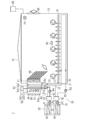
- FIG. 1 is a system diagram showing a poultry farming system (livestock building system) 1 according to the present embodiment.
- FIG. 2 is a systematic diagram which shows the heat pump 20 of the poultry farming system 1 which concerns on this embodiment.
- FIG. 3 is a system diagram showing the poultry farming system 1 when the aeration glari 54 and the adjustment plate 55 are inclined downward.
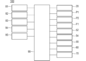
- FIG. 4 is a block diagram showing a configuration of the environment index sensor 80 of the poultry farming system 1 according to the present embodiment.
- FIG. 5 is a block diagram for explaining the function of the environment index unit 100 of the poultry farming system 1 according to the present embodiment.
- the poultry farming system 1 cools the chicken house 10, a heat pump 20 capable of simultaneously taking cold heat and heat, a heating path 30 for heating the inside of the chicken house 10, and a chicken house 10.
- Cooling path 40 Adjustment unit 50 for adjusting temperature and humidity in chicken house 10
- Exhaust fan 60 for exhausting air in chicken house 10
- Sterilizer 70 for sterilizing chicken house 10
- Chicken or chicken It has environmental index sensor 80 which detects a parameter for calculating an discomfort index, and control part 90 which controls various members of poultry farming system 1.
- the environmental index sensor 80 and the control unit 90 constitute an environmental index unit 100.
- Chicken house 10 has floor surface 11, left side wall 12, and right side wall 13 as shown in FIG. For example, a laying straw is placed on the floor surface 11, and chicks and chickens are reared thereon. A heating path 30 is disposed below the floor surface 11.
- the adjustment unit 50 is attached to the left side wall 12. Further, an exhaust fan 60 is attached to the right side wall 13.
- the heat pump 20 is configured to be able to simultaneously take cold heat and heat. Further, the heat pump 20 is configured to be able to take out only heat or only cold together with a heating tank 32 and a cooling tank 42 which will be described later. Since the heat pump 20 is an electric type, it does not use fire and there is no need to worry about fire. Hereinafter, the configuration of the heat pump 20 will be described in detail with reference to FIG.
- the heat pump 20 includes a refrigerant flow path 21 in which the refrigerant circulates, a compressor 22 that compresses the refrigerant, an expansion valve 23 that expands the refrigerant, and a first medium that circulates in the heating path 30.
- a heat exchanger 24 for supplying heat, and a cold heat exchanger 25 for supplying cold heat to a second medium circulating in the cooling passage 40 are provided.
- the refrigerant circulating through the refrigerant channel 21 is not particularly limited, but carbon dioxide can be used, for example.
- the compressor 22 is provided in the refrigerant channel 21. Although the compressor 22 is not particularly limited, for example, a CO 2 compressor can be used. The compression of the refrigerant as it passes through the compressor 22 raises the temperature of the refrigerant.
- the expansion valve 23 is provided in the refrigerant channel 21.
- the expansion valve 23 reduces the temperature of the refrigerant by being expanded when the refrigerant passes through the expansion valve 23.
- the heat exchanger 24 is disposed between the compressor 22 and the expansion valve 23.
- the thermal heat exchanger 24 heats the first medium circulating in the heating path 30 by the high-temperature refrigerant circulating from the compressor 22 toward the expansion valve 23.
- the temperature of the first medium heated by the heat exchanger 24 can be, for example, 65 ° C. or 90 ° C.
- the cold heat exchanger 25 is disposed between the expansion valve 23 and the compressor 22.
- the cold heat exchanger 25 cools the second medium circulating in the cooling path 40 by the low temperature refrigerant circulating from the expansion valve 23 toward the compressor 22.
- the temperature of the second medium cooled by the cold heat exchanger 25 is, for example, 7 to 10 ° C.
- the thermal heat exchanger 24 heats the first medium circulating in the heating path 30, and the cold heat exchanger 25 circulates in the cooling path 40. 2 Cool the medium. For this reason, the heat pump 20 is in a state where it is possible to simultaneously take out heat and cold.
- the heating path 30 heats the inside of the poultry house 10 by the circulation of the first medium heated by the heat taken out of the heat pump 20.
- the heating path 30 includes a first heating path 31 receiving heat from the heat heat exchanger 24, and a heating tank 32 storing the first medium receiving heat from the heat heat exchanger 24.
- a second heating path 33 disposed below the floor of the poultry house 10 and a third heating path 34 of which a portion passes through the inside of the adjustment unit 50 are provided.
- the circulation of the first medium in the first heating path 31 is performed by the first heating pump P1.
- the circulation of the first medium in the second heating path 33 is performed by the second heating pump P2.
- the first medium circulating in the first heating path 31, the second heating path 33, and the third heating path 34 is not particularly limited, and is, for example, water.
- the first medium which has received the heat from the heat exchanger 24 circulates. Then, in the heating tank 32, the first medium which has received the heat from the heat-to-heat heat exchanger 24 is stored. By storing the first medium in the heating tank 32 in this manner, the first medium can be sent to the second heating path 33 at a desired timing.
- the second heating path 33 is branched from the third heating path 34 at the branch portion J1.
- the third heating path 34 merges with the second heating path 33 at the merging portion J2.
- the outer circumference of the pipe constituting the first heating path 31, the second heating path 33, and the third heating path 34 is preferably made to have corrosion resistance.
- the cooling path 40 cools the inside of the poultry house 10 by circulating the second medium cooled by the cold extracted from the heat pump 20.
- the cooling path 40 includes a first cooling path 41 receiving cold heat from the cold heat exchanger 25, a cooling tank 42 in which a second medium receiving cold heat from the cold heat exchanger 25 is stored, and a part of the adjusting unit 50. And a second cooling path 43 passing through the inside.
- the circulation of the second medium in the first cooling path 41 is performed by the first cooling pump P3, as shown in FIG.
- the circulation of the second medium in the second cooling path 43 is performed by the second cooling pump P4.
- the second medium circulating in the first cooling path 41 and the second cooling path 43 is not particularly limited, and is, for example, water.
- a second medium which receives cold heat from the cold heat exchanger 25 circulates. Then, the second medium which has received the cold heat from the cold heat exchanger 25 is stored in the cooling tank 42. By storing the second medium in the cooling tank 42 in this manner, the second medium can be sent to the second cooling path 43 at a desired timing.
- the outer circumference of the pipe constituting the first cooling path 41 and the second cooling path 43 have corrosion resistance.
- heating path 30 and the cooling path 40 are provided as described above, only the heat can be taken out by turning on the second heating pump P2 and turning off the second cooling pump P4. On the other hand, only the cold heat can be taken out by turning off the second heating pump P2 and turning on the second cooling pump P4.
- the adjustment unit 50 adjusts the temperature and humidity in the poultry house 10. As described above, the adjustment unit 50 is configured such that the third heating path 34 and the second cooling path 43 pass through the inside.
- the adjustment unit 50 includes a case 51, a humidification unit 52 for humidifying the inside of the poultry house 10, and a cleaning unit 53 for cleaning the third heating path 34 and the second cooling path 43.
- the humidifying unit 52 sprays water inside the case 51.
- An opening 51 a for passing the third heating path 34 and the second cooling path 43 is formed on the lower surface of the case 51. Further, the lower surface of the case 51 is formed in a tapered shape so as to be directed downward to the right. For this reason, the water which came out of humidification part 52 and washing part 53 moves to the lower right side in the undersurface of adjustment part 50, and is drained from the drainage port (not shown) provided in the lower right side. For this reason, it can prevent that water accumulates in case 51.
- the left side surface 51 b of the case 51 is provided with a ventilation gutter 54 for adjusting the amount of air taken into the poultry house 10.
- a ventilation gutter 54 for adjusting the amount of air taken into the poultry house 10.
- the humidifying unit 52 is provided on the outside (left side in FIG. 1) of the second cooling path 43 passing through the inside of the case 51.
- the humidifying unit 52 includes a first storage unit 521 in which water is stored, and a first supply unit 522 that supplies the water stored in the first storage unit 521 to the inside of the case 51.
- the water supplied from the first supply unit 522 moves downward in the case 51 in the form of a mist.
- the cleaning unit 53 is provided above the third heating path 34 and the second cooling path 43 passing through the inside of the case 51.
- the cleaning unit 53 includes a second storage unit 531 in which water is stored, and a second supply unit 532 that supplies the water stored in the second storage unit 531 toward the third heating path 34 and the second cooling path 43. And.
- the water supplied from the second supply unit 532 may be in the form of a mist or in the form of droplets.
- the water supplied from the second supply unit 532 moves toward the third heating path 34 and the second cooling path 43 passing through the inside of the case 51, and the third heating path 34 and the second cooling path 43 in the case 51. Wash.
- the supply fan F1 is disposed on the right side of the case 51 of the adjustment unit 50.
- the supply fan F ⁇ b> 1 supplies the air in the adjusting unit 50 and misty water into the poultry house 10.
- an adjustment plate 55 is provided which adjusts the direction of the wind supplied into the poultry house 10 by the supply fan F1.
- the adjusting plate 55 is configured to be rotatable so as to rotate clockwise from the state in the horizontal direction shown in FIG. 1 and to be inclined downward on the side shown in FIG.
- the direction of the wind supplied from the adjustment unit 50 into the poultry house 10 is in the horizontal direction. At this time, the wind does not directly hit the chickens or chicks reared in the poultry house 10. Furthermore, at this time, since the wind flows toward the exhaust fan 60, the inside of the poultry house 10 can be suitably ventilated.
- the second heating pump P2 is stopped to turn off the circulation of the third heating path 34 of the first medium, and the second cooling pump P4 is operated to perform the second cooling of the second medium.
- the circulation of the path 43 By turning on the circulation of the path 43, the inside of the poultry house 10 can be cooled.
- the second heating pump P2 is operated to turn on the circulation of the third heating path 34 of the first medium, and the second cooling pump P4 is stopped to perform the second cooling path of the second medium. By turning off the circulation of 43, the house 10 can be heated.
- the second heating pump P2 is stopped to turn off the circulation of the third heating path 34 of the first medium, and the second cooling pump P4 is operated to operate the second cooling path of the second medium.
- the air in the vicinity of the adjustment unit 50 is cooled by the second medium to convert moisture into water droplets and remove condensation, thereby releasing dry air and It can be dehumidified.
- the humidifying unit 52 sprays water into the case 51 so that misty water is supplied into the poultry house 10, whereby the inside of the poultry house 10 can be humidified.
- the sterilizer 70 is provided in the chicken house 10 and sterilizes the chicken house 10.
- an excimer lamp can be used, for example.
- ozone and radicals having good diffusibility are generated to suppress sterilization and the growth of viruses, and the deodorizing effect on odor and NH 3 can be enhanced. Therefore, the NH 3 concentration in the poultry house 10 can be reduced by operating the sterilizer 70, and the growth of salmon can be safely promoted by realizing a comfortable environment.
- the environmental index sensor 80 detects the temperature in the house 10, humidity, and the wind speed blown against the chicken or chicken, which are parameters for calculating the chicken or chicken discomfort index. In addition, the environmental index sensor 80 detects the CO 2 concentration and the NH 3 concentration in the poultry house 10.
- the environmental index sensor 80 is attached to, for example, a feeder or a water feeder of the poultry house 10.
- the environment index sensor 80 may be provided in a ceiling-hanging manner. As shown in FIG. 4, the environmental index sensor 80 is a temperature sensor 81 for detecting the temperature in the poultry house 10, a humidity sensor 82 for detecting the humidity in the poultry house 10, and a wind speed sensor 83 for detecting the wind velocity in the poultry house 10.
- the NH 3 concentration sensor 85 for detecting the NH 3 concentration in poultry house 10
- Well-known sensors can be used as the temperature sensor 81, the humidity sensor 82, the wind speed sensor 83, the CO 2 concentration sensor 84, and the NH 3 concentration sensor 85, respectively.
- Control unit 90 controls the above-described units and performs various processes.
- Control unit 90 includes a CPU and a memory.
- the control unit 90 is based on the temperature in the poultry house 10 detected by the temperature sensor 81, the humidity in the poultry house 10 detected by the humidity sensor 82, and the wind speed blown against the chicken or chick detected by the wind speed sensor 83. Calculate the discomfort index of chicken, chicken or chicks.
- the temperature in the house 10 detected by the temperature sensor 81, the humidity in the house 10 detected by the humidity sensor 82, and the chicken or chick detected by the wind speed sensor 83 when calculating the discomfort index It is not necessary to use all the blowing wind speeds, and can be omitted appropriately according to the external environment. That is, in the present specification, the discomfort index is calculated based on at least one of temperature, humidity, and wind speed.
- the control unit 90 controls the flow rate of cold and warm heat extracted from the heat pump 20, the drive of the humidifying unit 52, and the air volume of the supply fan F1 such that the calculated discomfort index approaches a desired value. More specifically, the control unit 90 includes the heat pump 20, the first heating pump P1, the second heating pump P2, the first cooling pump P3, the second cooling pump P4, the supply fan F1, the humidifying unit 52, the ventilation gutter 54, And by controlling the adjusting plate 55, the discomfort index approaches the desired value.
- the "desired value of the discomfort index” refers to the numerical value of the discomfort index when a chicken or chick feels comfortable. Chickens or chicks generally feel hot when the number of discomfort indices is greater than the desired value and cold when they are less than the desired value.
- each member when the discomfort index calculated in the control unit 90 is larger than the desired value, each member is controlled so that the chicken or chick feels cool. In addition, when the discomfort index calculated in the control unit 90 is smaller than a desired value, each member is controlled so that the chicken or chick feels warm.
- the control unit 90 when the NH 3 concentration detected by the CO 2 concentration and the NH 3 concentration sensor 85 is detected by the CO 2 concentration sensor 84 exceeds a predetermined threshold, CO 2 poultry houses 10
- the supply fan F 1, the ventilation gutter 54, the adjusting plate 55, the exhaust fan 60, and the sterilizer 70 are controlled so that the concentration and the NH 3 concentration become equal to or lower than the threshold.
- the threshold value of the CO 2 concentration is, for example, 3000 ppm
- the threshold value of the NH 3 concentration is, for example, 10 ppm.
- control method of the control part 90 of the poultry farming system 1 which concerns on this embodiment is demonstrated in detail.
- control method of the control unit 90 of the poultry farming system 1 will be described by dividing the season into summer and winter.
- the environmental index sensor 80 detects the temperature in the poultry house 10, the humidity in the poultry house 10, and the wind speed blown against the chicken or chick. Further, the environmental index sensor 80 detects the CO 2 concentration and the NH 3 concentration in the poultry house 10.
- control unit 90 cools or dehumidifies the inside of the poultry house 10 by controlling each part as follows to reduce the discomfort index of the chicken or chick.
- the control unit 90 makes it possible to take out only cold heat by turning off the second heating pump P2 and turning on the second cooling pump P4.
- the control unit 90 tilts the adjusting plate 55 downward as shown in FIG.
- Chickens do not have sweat glands and are covered with feathers, so they can not regulate their body temperature by sweating, so heat is less likely to be dissipated, and heat is likely to build up in the body. For this reason, temperature regulation can not catch up if there is a rapid rise in the outside air temperature. Since the control unit 90 inclines the adjusting plate 55 downward, the cold air directly strikes the chicken, so that the chicken's discomfort index can be made close to a desired value.
- the control unit 90 makes the adjusting plate 55 horizontal as shown in FIG. Since there is less feathers in the cocoon, when the wind is hit directly, there is a risk that the temperature will drop sharply and harm your health.
- the adjustment plate 55 By setting the adjustment plate 55 in the horizontal direction as described above, the cool wind does not hit the eyelid, so that the body temperature of the eyelid can be prevented from sharply decreasing, and the eyelid's discomfort index is desired. It can be close to the value.
- control unit 90 may operate the second heating pump P2 and the second cooling pump P4. At this time, the floor surface 11 can be warmed by floor heating by the second heating path 33. At this time, the adjusting unit 50 can dehumidify the inside of the poultry house 10 as described above. This allows the discomfort index of the eyelids to be close to the desired value.
- control unit 90 when the control unit 90 detects that the concentration of CO 2 and the concentration of NH 3 in the poultry house 10 exceed the threshold, the control unit 90 controls the supply fan F1, the exhaust fan 60, and the ventilation gutter 54. , The adjustment plate 55, and the sterilizer 70 are controlled. Specifically, the control unit 90 turns on the supply fan F1 and the exhaust fan 60, and turns the ventilation grille 54 and the adjustment plate 55 horizontally as shown in FIG. 1, and turns on the sterilizer 70. Do. By this, the CO 2 concentration and the NH 3 concentration in the poultry house 10 can be reduced to the threshold value or less.
- the environmental index sensor 80 detects the temperature in the poultry house 10, the humidity in the poultry house 10, and the wind speed blown against the chicken or chick. Further, the environmental index sensor 80 detects the CO 2 concentration and the NH 3 concentration in the poultry house 10.
- control part 90 heats or humidifies the inside of the poultry house 10 by controlling each part as follows, and increases the discomfort index of a chicken or a chick.
- the control unit 90 turns on the second heating pump P2 and turns off the second cooling pump P4, so that only the heat can be taken out.
- the second heating path 33 heats the inside of the chicken house 10 from under the floor of the chicken house 10. Further, warm air is supplied from the adjustment unit 50 into the chicken house 10 to heat the chicken house 10. This can increase the chicken or chick discomfort index to approach the desired value. This results in a more comfortable environment for chickens or chicks.
- control unit 90 causes the humidifying unit 52 to spray water into the case 51 to supply mist-like water into the chicken house 10, thereby humidifying the inside of the chicken house 10.
- the humidifying unit 52 to spray water into the case 51 to supply mist-like water into the chicken house 10, thereby humidifying the inside of the chicken house 10.
- control method of the control unit 90 in the case where the CO 2 concentration and NH 3 concentration in the poultry house 10, which is detected in the environmental index sensor 80 exceeds the threshold value is the same as the method described in the summer, the description I omit it.
- control unit 90 dehumidifies the inside of the poultry house 10 by turning on the dehumidifying function in the adjustment unit 50.
- the first medium when used to heat the chicken house 10, it is preferable to use, for example, 65 ° C. as the temperature of the first medium.
- the first medium when the first medium is subjected to drying in the poultry house 10 in an open house period, for example, 90 ° C. is preferably used as the temperature of the first medium.
- the drying period can be shortened by raising the temperature of the first medium in the vacant period, and the vacant period can be shortened, for example, for 2 days. Therefore, the productivity of the poultry farming system 1 can be improved.
- the environmental index unit 100 detects the temperature sensor 81 detecting the temperature in the poultry house 10, the humidity sensor 82 detecting the humidity in the poultry house 10, and the wind speed blowing to the chicken or chicks wind sensor 83, the environmental index sensor 80 comprises at least one of NH 3 concentration sensor 85 for detecting the NH 3 concentration in the CO 2 concentration sensor 84, and poultry 10 for detecting the CO 2 concentration in poultry house 10, the environment Based on the temperature, humidity, and wind speed detected by the index sensor 80, the chicken or chick discomfort index is calculated, and the temperature, humidity in the poultry house 10, and the like so that the calculated discomfort index approaches a desired value.
- the environmental index unit 100 configured as described above, the temperature in the chicken house 10, the humidity in the chicken house 10, the wind speed blowing to the chicken or chick, the CO 2 concentration in the chicken house 10, and the chicken house 10
- the NH 3 concentration in the inside is detected.
- the control unit 90 calculates the discomfort index based on the temperature, humidity, and wind speed detected by the environment index sensor 80, and the temperature in the chicken house 10 and the chicken house 10 so that the calculated discomfort index approaches a desired value.
- the control unit 90 controls the air conditioning in the poultry house 10 so that the CO 2 concentration and the NH 3 concentration become lower than the threshold. Then, the CO 2 concentration and the NH 3 concentration in the poultry house 10 are automatically adjusted. Therefore, the temperature in the chicken house 10, the humidity in the chicken house 10, the wind speed blown against the chicken or chick, the CO 2 concentration in the chicken house 10, and the NH 3 concentration in the chicken house 10 are automatically adjusted to An environmental index unit 100 can be provided which can make the eyelids not uncomfortable.
- the poultry farming system 1 is attached to the above-described environmental index unit 100, the heat pump 20 capable of extracting at least one of cold and warm heat, and the chicken house 10
- the exhaust fan 60 for exhausting the air in the poultry house 10 and the control unit 90 causes the heat pump 20 to make the calculated discomfort index approach a desired value.
- the environmental index sensor 80 detects the temperature in the poultry house 10, the humidity in the poultry house 10, and the wind speed blowing to the chicken or chick. Further, the control unit 90 calculates the discomfort index based on the temperature, humidity, and wind speed detected by the environment index sensor 80, and the cold energy and the cold energy extracted from the heat pump 20 so that the calculated discomfort index approaches a desired value.
- the flow rate of the heat, the drive of the humidifying unit 52, and the air volume of the supply fan F1 are controlled to automatically adjust the temperature in the chicken house 10, the humidity in the chicken house 10, and the wind speed blown to the chicken or chick. For this reason, it is possible to automatically adjust the temperature in the chicken house 10, the humidity in the chicken house 10, and the wind speed blowing to the chicken or chicks so that the chicken or chicks do not feel uncomfortable. Can be provided. Also, the CO 2 and NH 3 concentrations in the house 10 can be automatically adjusted to make the chicken or chicks not uncomfortable.
- the poultry farming system 1 further includes a sterilizer 70 for sterilizing the inside of the chicken house 10, and the control unit 90 causes the NH 3 concentration to be equal to or less than the threshold when the NH 3 concentration in the chicken house 10 exceeds a threshold. , Control the sterilizer 70.
- the NH 3 concentration in the poultry house 10 can be adjusted automatically and quickly.
- the adjusting unit 50 is attached with a ventilation grate 54 for adjusting the amount of air taken into the poultry house 10, so that the control unit 90 causes the discomfort index calculated by the control unit 90 to approach a desired value. , Control the degree of opening and closing of the ventilation air 54.
- the temperature in the poultry house 10, the humidity in the poultry house 10, and the wind speed blowing to the chicken or chick can be adjusted automatically and quickly.
- the adjustment board 55 which adjusts the direction of the wind which blows off from the adjustment part 50 is provided inside the house of the chicken house 10 among the adjustment parts 50, and the discomfort index calculated by the control part 90 is The orientation of the adjusting plate 55 is controlled to approach a desired value.
- the temperature in the poultry house 10, the humidity in the poultry house 10, and the wind speed blowing to the chicken or chick can be adjusted automatically and quickly.
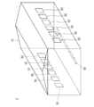
- FIG. 6 is a schematic perspective view showing a poultry farming system 2 according to a first modification.
- the poultry farming system 2 according to the first modification differs from the poultry farming system 1 according to the embodiment in that an adjusting unit 50, an exhaust fan 60, and an environmental index sensor 80 are provided in the longitudinal direction of the poultry house 10.
- a plurality of environmental index sensors 80 are disposed along the longitudinal direction, the temperature and humidity at a plurality of locations where the environmental index sensors 80 are disposed , Wind speed, CO 2 concentration, and NH 3 concentration can be detected. Therefore, since temperature, humidity, wind speed, CO 2 concentration, and NH 3 concentration can be adjusted at each location, it is possible to more reliably prevent chickens or chicks from feeling unpleasant. Furthermore, a plurality of environmental index sensors 80 detect the number of fattenings of the chicken house 10, the location conditions, the size, and the characteristics specific to the chicken house 10 according to the structure (the flow of the wind in the chicken house 10 and the clearance conditions). , It is useful for repair of the chicken house 10 and grasp of the optimum fattening place.
- the present invention is applied to a poultry farming system that breeds chickens as a livestock house system, but can also be applied to breeding of pigs and the like.
- the poultry farming system 1 includes the sterilizer 70, and the control unit 90 controls the sterilizer 70.
- the poultry system may not have a sterilizer.
- the ventilation gutter 54 is attached to the adjustment unit 50, and the control unit 90 controls the ventilation gutter 54.
- the ventilation gutter may not be attached to the adjustment unit.
- the adjusting unit 50 is provided with the adjusting plate 55, and the control unit 90 controls the adjusting plate 55.
- the adjusting plate may not be provided in the adjusting unit.
- the adjusting unit 50, the exhaust fan 60, and the environmental index sensor 80 are provided in the longitudinal direction of the poultry house 10.
- a plurality of adjustment units 50, exhaust fans 60, and environmental index sensors 80 may be provided in the lateral direction of the poultry house 10.
- a hygrometer capable of measuring the humidity of the floor surface 11 may be further disposed on the floor surface 11.
- the chicken excrement excreted during fattening is dried since it is used as a bedding until the shipment of the meat chicken.
- the heating path 30 has the heating tank 32, and the cooling path 40 has the cooling tank 42.
- the heating path may not include the heating tank, and the cooling path may not include the cooling tank.
- a radiator for exhausting the cold heat and the warm heat extracted from the heat pump is provided.
- the adjustment unit 50 is attached to the poultry house 10.
- the adjustment unit 50 may not be directly attached to the poultry house 10, and the temperature and humidity of the poultry house 10 may be adjusted by a duct system.
- the discomfort index was made close to the desired value using the heat and cold which are taken out from the heat pump 20. As shown in FIG. However, the discomfort index may be brought close to the desired value using the heat provided by the boiler and the cold provided by the cold water filter.
- the humidifying unit sprays water to humidify the inside of the chicken house 10, but the humidifying unit may supply water vapor to humidify the chicken house 10.
- the circulation of the first medium in order to dehumidify the inside of the poultry house 10 in the adjustment unit 50, the circulation of the first medium is turned off and the circulation of the second medium is turned on.
- the circulation of the first medium in order to dehumidify the inside of the poultry house 10, the circulation of the first medium may be turned on and the circulation of the second medium may be turned on.
- the dehumidifying mode has been described using a so-called compressor system that dehumidifies using condensation generated by cooling air.
- it may be dehumidified by a so-called desiccant method of dehumidifying by adsorbing the moisture to the desiccant.
Landscapes
- Life Sciences & Earth Sciences (AREA)
- Environmental Sciences (AREA)
- Zoology (AREA)
- Animal Husbandry (AREA)
- Biodiversity & Conservation Biology (AREA)
- Housing For Livestock And Birds (AREA)
Abstract
Le problème décrit par la présente invention est d'obtenir une unité d'indice environnemental qui permet de régler automatiquement la température à l'intérieur d'une étable, l'humidité à l'intérieur de l'étable, la vitesse de l'air soufflant sur le bétail, la concentration en CO2 à l'intérieur de l'étable, et la concentration en NH3 à l'intérieur de l'étable, et de s'assurer ainsi que le bétail ne ressente pas d'inconfort. La solution selon l'invention porte sur une unité d'indice environnemental (100) qui est pourvue : d'un capteur d'indice environnemental (80) qui est équipé d'un capteur de température (81) et/ou d'un capteur d'humidité (82) et/ou d'un capteur de vitesse du vent (83) et/ou d'un capteur de concentration en CO2 (84) et/ou d'un capteur de concentration en NH3 (85) ; et d'une unité de commande (90) qui régule la température, l'humidité et la vitesse du vent à l'intérieur d'une étable de sorte que l'indice de température-humidité s'approche d'une valeur souhaitée, et qui commande la ventilation à l'intérieur de l'étable de sorte que la concentration en CO2 et la concentration en NH3 soient inférieures ou égales à une valeur seuil.
Priority Applications (3)
| Application Number | Priority Date | Filing Date | Title |
|---|---|---|---|
| PCT/JP2017/039590 WO2019087336A1 (fr) | 2017-11-01 | 2017-11-01 | Unité d'indice environnemental et système d'étable |
| PCT/JP2018/040724 WO2019088228A1 (fr) | 2017-11-01 | 2018-11-01 | Unité d'indice environnemental et système de stalle pour le bétail |
| JP2019550486A JP7245781B2 (ja) | 2017-11-01 | 2018-11-01 | 家畜舎システム |
Applications Claiming Priority (1)
| Application Number | Priority Date | Filing Date | Title |
|---|---|---|---|
| PCT/JP2017/039590 WO2019087336A1 (fr) | 2017-11-01 | 2017-11-01 | Unité d'indice environnemental et système d'étable |
Publications (1)
| Publication Number | Publication Date |
|---|---|
| WO2019087336A1 true WO2019087336A1 (fr) | 2019-05-09 |
Family
ID=66331636
Family Applications (2)
| Application Number | Title | Priority Date | Filing Date |
|---|---|---|---|
| PCT/JP2017/039590 Ceased WO2019087336A1 (fr) | 2017-11-01 | 2017-11-01 | Unité d'indice environnemental et système d'étable |
| PCT/JP2018/040724 Ceased WO2019088228A1 (fr) | 2017-11-01 | 2018-11-01 | Unité d'indice environnemental et système de stalle pour le bétail |
Family Applications After (1)
| Application Number | Title | Priority Date | Filing Date |
|---|---|---|---|
| PCT/JP2018/040724 Ceased WO2019088228A1 (fr) | 2017-11-01 | 2018-11-01 | Unité d'indice environnemental et système de stalle pour le bétail |
Country Status (2)
| Country | Link |
|---|---|
| JP (1) | JP7245781B2 (fr) |
| WO (2) | WO2019087336A1 (fr) |
Cited By (4)
| Publication number | Priority date | Publication date | Assignee | Title |
|---|---|---|---|---|
| FR3100316A1 (fr) * | 2019-09-03 | 2021-03-05 | Bhf | Système de renouvellement d’air et de chauffage pour bâtiments d'élevage, notamment d’élevage avicole. |
| CN112450083A (zh) * | 2020-09-09 | 2021-03-09 | 中国农业大学 | 一种畜禽舍通风分区控制方法 |
| CN114279104A (zh) * | 2021-11-15 | 2022-04-05 | 珠海格力电器股份有限公司 | 养殖舍用冷热源机组及养殖舍环控系统 |
| JP2023081692A (ja) * | 2021-12-01 | 2023-06-13 | 人吉アサノ電機株式会社 | 畜舎管理装置、畜舎、及び、畜舎管理方法 |
Families Citing this family (2)
| Publication number | Priority date | Publication date | Assignee | Title |
|---|---|---|---|---|
| WO2021014920A1 (fr) * | 2019-07-25 | 2021-01-28 | パナソニックIpマネジメント株式会社 | Système de commande de ventilation et procédé de commande de ventilation |
| KR20230084234A (ko) * | 2020-10-07 | 2023-06-12 | 씨티비, 인크. | 인클로저에서 동물을 관리하기 위한 장치 및 방법 |
Citations (8)
| Publication number | Priority date | Publication date | Assignee | Title |
|---|---|---|---|---|
| JPS5614941B2 (fr) * | 1978-03-08 | 1981-04-07 | ||
| JPS5616858B2 (fr) * | 1978-09-28 | 1981-04-18 | ||
| JP3077065B2 (ja) * | 1991-04-08 | 2000-08-14 | 清水建設株式会社 | 動物飼育室の空調制御システム |
| JP2004037031A (ja) * | 2002-07-05 | 2004-02-05 | Sumitomo Heavy Industries Construction Crane Co Ltd | 冷却器の開口部調整装置 |
| US8181604B1 (en) * | 2007-05-22 | 2012-05-22 | David Avila | Barn system for housing farm animals |
| JP2013208938A (ja) * | 2012-03-30 | 2013-10-10 | Mitsubishi Heavy Ind Ltd | 車室外熱交換器の着霜回避装置及び車両用空調装置 |
| JP5866547B2 (ja) * | 2013-08-30 | 2016-02-17 | パナソニックIpマネジメント株式会社 | 畜舎 |
| JP6145754B2 (ja) * | 2012-07-02 | 2017-06-14 | 宮崎県 | 家畜体の環境緩和装置 |
Family Cites Families (5)
| Publication number | Priority date | Publication date | Assignee | Title |
|---|---|---|---|---|
| JPH05304832A (ja) * | 1992-04-27 | 1993-11-19 | Nagano Kogen Kinoko Kk | 栽培室、畜舎等の加湿装置 |
| NL1007583C2 (nl) * | 1997-11-19 | 1999-05-20 | Bokalan B V | Stal voorzien van een klimaatregelsysteem, wasorgaan alsmede een werkwijze voor het regelen van het klimaat in een dergelijke stal. |
| JP3954000B2 (ja) | 2003-10-01 | 2007-08-08 | 株式会社高橋工業 | 家畜舎管理システム |
| JP2012047433A (ja) | 2010-08-30 | 2012-03-08 | Biolink:Kk | 空調構造 |
| JP2013143923A (ja) | 2012-01-16 | 2013-07-25 | Toshiba Carrier Corp | 空気調和機 |
-
2017
- 2017-11-01 WO PCT/JP2017/039590 patent/WO2019087336A1/fr not_active Ceased
-
2018
- 2018-11-01 JP JP2019550486A patent/JP7245781B2/ja active Active
- 2018-11-01 WO PCT/JP2018/040724 patent/WO2019088228A1/fr not_active Ceased
Patent Citations (8)
| Publication number | Priority date | Publication date | Assignee | Title |
|---|---|---|---|---|
| JPS5614941B2 (fr) * | 1978-03-08 | 1981-04-07 | ||
| JPS5616858B2 (fr) * | 1978-09-28 | 1981-04-18 | ||
| JP3077065B2 (ja) * | 1991-04-08 | 2000-08-14 | 清水建設株式会社 | 動物飼育室の空調制御システム |
| JP2004037031A (ja) * | 2002-07-05 | 2004-02-05 | Sumitomo Heavy Industries Construction Crane Co Ltd | 冷却器の開口部調整装置 |
| US8181604B1 (en) * | 2007-05-22 | 2012-05-22 | David Avila | Barn system for housing farm animals |
| JP2013208938A (ja) * | 2012-03-30 | 2013-10-10 | Mitsubishi Heavy Ind Ltd | 車室外熱交換器の着霜回避装置及び車両用空調装置 |
| JP6145754B2 (ja) * | 2012-07-02 | 2017-06-14 | 宮崎県 | 家畜体の環境緩和装置 |
| JP5866547B2 (ja) * | 2013-08-30 | 2016-02-17 | パナソニックIpマネジメント株式会社 | 畜舎 |
Cited By (5)
| Publication number | Priority date | Publication date | Assignee | Title |
|---|---|---|---|---|
| FR3100316A1 (fr) * | 2019-09-03 | 2021-03-05 | Bhf | Système de renouvellement d’air et de chauffage pour bâtiments d'élevage, notamment d’élevage avicole. |
| CN112450083A (zh) * | 2020-09-09 | 2021-03-09 | 中国农业大学 | 一种畜禽舍通风分区控制方法 |
| CN114279104A (zh) * | 2021-11-15 | 2022-04-05 | 珠海格力电器股份有限公司 | 养殖舍用冷热源机组及养殖舍环控系统 |
| JP2023081692A (ja) * | 2021-12-01 | 2023-06-13 | 人吉アサノ電機株式会社 | 畜舎管理装置、畜舎、及び、畜舎管理方法 |
| JP7702732B2 (ja) | 2021-12-01 | 2025-07-04 | 人吉アサノ電機株式会社 | 畜舎管理装置、畜舎、及び、畜舎管理方法 |
Also Published As
| Publication number | Publication date |
|---|---|
| JP7245781B2 (ja) | 2023-03-24 |
| JPWO2019088228A1 (ja) | 2020-11-12 |
| WO2019088228A1 (fr) | 2019-05-09 |
Similar Documents
| Publication | Publication Date | Title |
|---|---|---|
| JP7245781B2 (ja) | 家畜舎システム | |
| WO2019087335A1 (fr) | Système d'étable | |
| JP6989614B2 (ja) | 家畜舎システム | |
| ES2713064T3 (es) | Sistema de control climático en un entorno espacial para organismos, entorno espacial adaptado a este, sistema de control y programa para ello | |
| JP2022143985A (ja) | 恒温庫および保温材が装着された被服の初期化方法 | |
| KR101438257B1 (ko) | 육류 숙성을 위한 건조숙성고 | |
| EP1032258B1 (fr) | Ecurie equipee d'un systeme de regulation climatique, et procede de regulation climatique de cette ecurie | |
| JP2002051657A (ja) | 牛体冷房装置 | |
| US20240365742A1 (en) | Livestock-housing ventilation system | |
| JP6548338B2 (ja) | 家畜舎システム | |
| GB2603566A (en) | Livestock-housing ventilation system | |
| Jones et al. | Environmental control for confinement livestock housing | |
| CN113589872B (zh) | 一种猪舍温湿度控制方法、装置、系统及存储介质 | |
| CN206932916U (zh) | 用于牧场的奶牛休息大棚 | |
| KR102556633B1 (ko) | 환기시스템을 갖는 양돈 축사 | |
| CN210094279U (zh) | 家禽养殖专用除湿机 | |
| JP7657429B2 (ja) | 畜舎の冷房システム | |
| KR20150137567A (ko) | 축열식 공기소독 냉열 교환기 | |
| KR20110115265A (ko) | 습도 조절가능한 환기 장치 | |
| CN107295973A (zh) | 具有散热功能的奶牛休息棚 | |
| JP6608274B2 (ja) | 施設園芸用ハウスの湿度管理制御方法 | |
| House et al. | Ventilation options for free-stall barns | |
| KR200261159Y1 (ko) | 계사용 예열공기환풍장치 | |
| Bray et al. | Latest on tunnel barns for cow comfort | |
| Turnbull | Housing and environment for dairy calves |
Legal Events
| Date | Code | Title | Description |
|---|---|---|---|
| 121 | Ep: the epo has been informed by wipo that ep was designated in this application |
Ref document number: 17930458 Country of ref document: EP Kind code of ref document: A1 |
|
| NENP | Non-entry into the national phase |
Ref country code: DE |
|
| 122 | Ep: pct application non-entry in european phase |
Ref document number: 17930458 Country of ref document: EP Kind code of ref document: A1 |
|
| NENP | Non-entry into the national phase |
Ref country code: JP |