WO2019087400A1 - Dispositif de climatisation - Google Patents
Dispositif de climatisation Download PDFInfo
- Publication number
- WO2019087400A1 WO2019087400A1 PCT/JP2017/039977 JP2017039977W WO2019087400A1 WO 2019087400 A1 WO2019087400 A1 WO 2019087400A1 JP 2017039977 W JP2017039977 W JP 2017039977W WO 2019087400 A1 WO2019087400 A1 WO 2019087400A1
- Authority
- WO
- WIPO (PCT)
- Prior art keywords
- control
- indoor
- outdoor
- unit
- outside air
- Prior art date
- Legal status (The legal status is an assumption and is not a legal conclusion. Google has not performed a legal analysis and makes no representation as to the accuracy of the status listed.)
- Ceased
Links
Images

Classifications
-
- F—MECHANICAL ENGINEERING; LIGHTING; HEATING; WEAPONS; BLASTING
- F24—HEATING; RANGES; VENTILATING
- F24F—AIR-CONDITIONING; AIR-HUMIDIFICATION; VENTILATION; USE OF AIR CURRENTS FOR SCREENING
- F24F11/00—Control or safety arrangements
- F24F11/62—Control or safety arrangements characterised by the type of control or by internal processing, e.g. using fuzzy logic, adaptive control or estimation of values
-
- F—MECHANICAL ENGINEERING; LIGHTING; HEATING; WEAPONS; BLASTING
- F24—HEATING; RANGES; VENTILATING
- F24F—AIR-CONDITIONING; AIR-HUMIDIFICATION; VENTILATION; USE OF AIR CURRENTS FOR SCREENING
- F24F11/00—Control or safety arrangements
- F24F11/70—Control systems characterised by their outputs; Constructional details thereof
- F24F11/80—Control systems characterised by their outputs; Constructional details thereof for controlling the temperature of the supplied air
-
- F—MECHANICAL ENGINEERING; LIGHTING; HEATING; WEAPONS; BLASTING
- F24—HEATING; RANGES; VENTILATING
- F24F—AIR-CONDITIONING; AIR-HUMIDIFICATION; VENTILATION; USE OF AIR CURRENTS FOR SCREENING
- F24F11/00—Control or safety arrangements
- F24F11/70—Control systems characterised by their outputs; Constructional details thereof
- F24F11/80—Control systems characterised by their outputs; Constructional details thereof for controlling the temperature of the supplied air
- F24F11/86—Control systems characterised by their outputs; Constructional details thereof for controlling the temperature of the supplied air by controlling compressors within refrigeration or heat pump circuits
-
- F—MECHANICAL ENGINEERING; LIGHTING; HEATING; WEAPONS; BLASTING
- F25—REFRIGERATION OR COOLING; COMBINED HEATING AND REFRIGERATION SYSTEMS; HEAT PUMP SYSTEMS; MANUFACTURE OR STORAGE OF ICE; LIQUEFACTION SOLIDIFICATION OF GASES
- F25B—REFRIGERATION MACHINES, PLANTS OR SYSTEMS; COMBINED HEATING AND REFRIGERATION SYSTEMS; HEAT PUMP SYSTEMS
- F25B1/00—Compression machines, plants or systems with non-reversible cycle
Definitions
- the present disclosure relates to an air conditioner having a plurality of outdoor units.
- an air conditioner configured by connecting a plurality of outdoor units having a compressor and an outdoor heat exchanger, and an indoor unit having an indoor heat exchanger.
- start control involving the start of the compressor is performed, and after the start control is completed, normal control is performed to control the operating capacity of the compressor according to the operating load of the indoor unit. To be done.
- start control the compressors of all the outdoor units are started.
- the pressure (high pressure in the refrigeration cycle) of the refrigerant discharged from the compressor during start control may be rapidly increased (high pressure abnormality).
- An object of the present disclosure is to suppress occurrence of high pressure abnormality at the time of start control in an air conditioner having a plurality of outdoor units.
- An air conditioner includes a refrigerant circuit configured by connecting a plurality of outdoor units having a compressor and an outdoor heat exchanger, and an indoor unit having an indoor heat exchanger, and a compressor And a control unit that controls the The control unit performs start control with starting of the compressor at the start of operation of the air conditioner, and performs normal control to control the operating capacity of the compressor according to the operation load of the indoor unit after the start control is completed. . Then, here, when the control unit determines that the outside air temperature is high and the operation load of the indoor unit is small at the time of start control, only one outdoor unit starts the compressor. Therefore, under conditions where there is a possibility of high pressure abnormality, the number of compressors to be started can be limited to a small number, and the occurrence of high pressure abnormality at the time of start control can be suppressed.
- the control unit determines that the outside air temperature is not high or the operation load of the indoor unit is not small at the time of activation control, the compressors of all the outdoor units are activated. Let For this reason, under conditions where there is no risk of high pressure abnormality, start control can be performed without limiting the number of compressors to be started.
- control unit determines whether the outside air temperature is high depending on whether the outside air temperature is equal to or higher than a predetermined value. Therefore, it can be clearly determined whether the outside air temperature is high.
- the operating load of the indoor unit depends on whether the operating load of the indoor unit at the time of activation control is equal to or less than a predetermined ratio with respect to the total value To determine if is smaller. Therefore, it can be clearly determined whether the operation load of the indoor unit is small.
- the operating load of the indoor units at the time of start control may be the total value of the operating loads of the indoor units.
- each of the outdoor units has an outside air temperature sensor for detecting the outside air temperature
- the control unit is the most out of the outside air temperatures detected by the outside air temperature sensor at the time of activation control.
- one outdoor unit activating the compressor is plural. If one of the plurality of compressors is activated, the compressor is activated. For this reason, under conditions where there is a possibility of high pressure abnormality, even if the outdoor unit has a plurality of compressors, the number of compressors to be started is limited to one, and high pressure abnormality occurs during start control. Can be suppressed.
- the control unit determines that the outside air temperature is high and the operation load of the indoor unit is small at the time of activation control, one outdoor unit that activates the compressor is Rotate each time the air conditioner starts operating. For this reason, under conditions where there is a possibility of high pressure abnormality, the compressor to be started can not be fixed to a specific compressor, and the compressor of each outdoor unit can be used evenly.
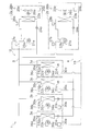
- FIG. 1 It is a schematic block diagram of the air conditioning apparatus concerning one embodiment of this indication. It is a control block diagram of an air conditioning apparatus. It is a flow chart which shows starting control. It is a schematic block diagram of the air conditioning apparatus concerning the modification A.
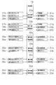
- FIG. 1 It is a schematic block diagram of the air conditioning apparatus concerning one embodiment of this indication. It is a control block diagram of an air conditioning apparatus. It is a flow chart which shows starting control. It is a schematic block diagram of the air conditioning apparatus concerning the modification A.
- FIG. 1 is a schematic refrigerant circuit diagram of an air conditioner 1 according to an embodiment of the present disclosure.
- the air conditioner 1 is a device mainly used for cooling a room such as a building by a vapor compression refrigeration cycle.
- the air conditioning apparatus 1 mainly includes a plurality of (here, two) outdoor units 2a and 2b connected in parallel to one another and a plurality (here, four) indoor units 3a to 3C connected in parallel to one another It has a liquid refrigerant communication pipe 4 and a gas refrigerant communication pipe 5 for connecting the outdoor unit 2 and the indoor units 3a to 3d.
- a vapor compression type refrigerant circuit 10 of the air conditioner 1 is configured. ing.
- Each of the indoor units 3a to 3d is configured to be able to individually turn on / off the operation.
- a refrigerant is sealed in the refrigerant circuit 10.
- the indoor units 3a to 3d are installed in a room such as a building. As described above, the indoor units 3a to 3d are connected to the outdoor units 2a and 2b via the liquid refrigerant communication pipe 4 and the gas refrigerant communication pipe 4, and constitute a part of the refrigerant circuit 10.
- the indoor unit 3a mainly includes an indoor expansion valve 31a and an indoor heat exchanger 32a.
- the indoor unit 3a mainly includes an indoor expansion valve 31a and an indoor heat exchanger 32a.
- the indoor expansion valve 31a is an electric expansion valve that adjusts the flow rate of the refrigerant flowing through the indoor heat exchanger 32a while reducing the pressure of the refrigerant to a low pressure in the refrigeration cycle during cooling operation, and the liquid refrigerant communication pipe 4 and the indoor heat exchanger 32a It is connected between the liquid side end.
- the indoor heat exchanger 32a is a heat exchanger that functions as an evaporator of low-pressure refrigerant in the refrigeration cycle to cool indoor air during cooling operation, and its liquid side end is connected to the indoor expansion valve 31a, and the gas side end Are connected to the gas refrigerant communication pipe 5.
- the indoor unit 3a also includes an indoor fan 33a for supplying indoor air as supply air after the indoor air is sucked into the indoor unit 3a and heat-exchanged with the refrigerant in the indoor heat exchanger 32a. . That is, the indoor unit 3a has the indoor fan 33a as a fan which sends indoor air as a heat source of the refrigerant flowing through the indoor heat exchanger 32a to the indoor heat exchanger 32a.
- the indoor fan 33a is driven by the indoor fan motor 34a.
- the indoor unit 3a includes a heat exchange outlet temperature sensor 35a for detecting the temperature Tga of the refrigerant at the outlet (gas side end) of the indoor heat exchanger 32a, and indoor air taken into the indoor unit 3a.
- An indoor temperature sensor 36a that detects a temperature (that is, an indoor temperature Tra) is provided.
- the indoor unit 3a has the indoor side control part 30a which controls operation
- the indoor control unit 30a has a microcomputer, a memory, and the like provided to control the indoor unit 3a, and exchanges control signals and the like with a remote control (not shown). It is possible to exchange control signals and the like with the outdoor units 2a and 2b.
- the outdoor units 2a and 2b are installed outside a building or the like.
- the outdoor units 2a and 2b are connected to the indoor units 3a to 3d via the liquid refrigerant communication pipe 4 and the gas refrigerant communication pipe 5 as described above, and constitute a part of the refrigerant circuit 10.
- the outdoor unit 2a mainly includes a compressor 21a, an outdoor heat exchanger 23a, and an outdoor expansion valve 24a.
- the compressor 21a is a device that compresses the low pressure refrigerant in the refrigeration cycle to a high pressure.
- a compressor of a closed type in which a positive displacement compression element (not shown) is rotationally driven by the compressor motor 22a is employed.
- the compressor motor 22a can control the number of rotations with an inverter or the like, whereby the compressor 21a is configured to be capable of capacity control (number of rotations control).
- the outdoor heat exchanger 23a is a heat exchanger that functions as a radiator of high-pressure refrigerant in the refrigeration cycle during cooling operation, and its gas side end is connected to the discharge side of the compressor 21a, and the liquid side end is outdoor. It is connected to the expansion valve 24a.
- the outdoor expansion valve 24 a is an electric expansion valve adjusted to an opening degree such as full opening during cooling operation, and is connected between the liquid side end of the outdoor heat exchanger 23 a and the liquid refrigerant communication pipe 4.
- the outdoor unit 2a has an outdoor fan 25a for discharging outdoor air after drawing outdoor air into the outdoor unit 2a and exchanging heat with a refrigerant in the outdoor heat exchanger 23a. That is, the outdoor unit 2a includes the outdoor fan 25a as a fan that sends outdoor air as a cooling source of the refrigerant flowing through the outdoor heat exchanger 23a to the outdoor heat exchanger 23a. The outdoor fan 25a is driven by the outdoor fan motor 26a.
- the outdoor unit 2a includes a suction pressure sensor 27a that detects the suction pressure Pe of the compressor 21a (that is, the low pressure in the refrigeration cycle or the equivalent saturation pressure of the evaporation temperature Te in the refrigeration cycle); A discharge pressure sensor 28a for detecting the discharge pressure Pc 21a (that is, the high pressure in the refrigeration cycle or the equivalent saturation pressure of the condensation temperature Tc in the refrigeration cycle), and the temperature of outdoor air taken into the outdoor unit 2a (that is, An outside air temperature sensor 29a for detecting the outside air temperature To) is provided.
- a suction pressure sensor 27a that detects the suction pressure Pe of the compressor 21a (that is, the low pressure in the refrigeration cycle or the equivalent saturation pressure of the evaporation temperature Te in the refrigeration cycle)
- a discharge pressure sensor 28a for detecting the discharge pressure Pc 21a (that is, the high pressure in the refrigeration cycle or the equivalent saturation pressure of the condensation temperature Tc in the refrigeration cycle)
- An outside air temperature sensor 29a for detecting the outside air temperature To
- the outdoor unit 2a has the outdoor side control part 20a which controls operation
- the outdoor side control part 20a has a microcomputer, a memory, etc. which were provided in order to control the outdoor unit 2a, and exchange of a control signal etc. between the outdoor side control part 20b of the outdoor unit 2b. And exchange of control signals and the like with the indoor side control units 30a to 30d of the indoor units 3a to 3d.
- the refrigerant communication pipes 4 and 5 are refrigerant pipes to be constructed on site when the air conditioning apparatus 1 is installed at an installation place such as a building, and installation conditions such as the installation place and the combination of the outdoor unit and the indoor unit Depending on the length and diameter of the tube are used.
- the air conditioner 1 controls each of the devices from the outdoor units 2a and 2b and the indoor units 3a to 3d by the control unit 19 including the indoor side control units 30a to 30d and the outdoor side control units 20a and 20b. It can be done. That is, the control unit 19 configured to perform operation control of the entire air conditioning apparatus 1 is configured by communication connection between the indoor control units 30a to 30d and the outdoor control units 20a and 20b.
- the control unit 19 is configured to be able to receive detection signals of various sensors such as pressure sensors 27a, 27b, 28a, 28b, temperature sensors 29a, 29b, 35a to 35d, 36a to 36d, etc.
- sensors such as pressure sensors 27a, 27b, 28a, 28b, temperature sensors 29a, 29b, 35a to 35d, 36a to 36d, etc.
- FIG. 2 is a control block diagram of the air conditioner 1.
- a cooling operation which is an operation to cool the room, is performed.
- the control unit 19 performs the start control with the start of the compressors 21a and 21b when the operation of the air conditioner 1 starts, and after the start control ends, the operation of the indoor units 3a to 3d Normal control is performed to control the operating capacities of the compressors 21a and 21b in accordance with the load.
- the refrigerant in the refrigerant circuit 10 is drawn into the compressors 21a and 21b and compressed to a high pressure from a low pressure in the refrigeration cycle and then discharged.
- the refrigerant in the gas state discharged from the compressors 21a and 21b flows into the gas side ends of the outdoor heat exchangers 23a and 23b.
- the refrigerant flowing into the gas side ends of the outdoor heat exchangers 23a and 23b exchanges heat with the outdoor air supplied by the outdoor fans 25a and 25b in the outdoor heat exchangers 23a and 23b, radiates heat, and is in the liquid state It flows out from the liquid side end of outdoor heat exchanger 23a, 23b.
- the refrigerant flowing out from the liquid side ends of the outdoor heat exchangers 23a and 23b is sent to the indoor units 3a to 3d through the outdoor expansion valves 24a and 24b and the liquid refrigerant communication pipe 4.
- the refrigerant sent to the indoor units 3a to 3d is decompressed to around the low pressure in the refrigeration cycle by the indoor expansion valves 31a to 31d.
- the refrigerant after being decompressed by the indoor expansion valves 31a to 31d flows into the liquid side ends of the indoor heat exchangers 32a to 32d.
- the refrigerant that has flowed into the liquid side end of the indoor heat exchangers 32a to 32d exchanges heat with the indoor air supplied by the indoor fans 33a to 33d in the indoor heat exchangers 32a to 32d to evaporate and evaporate the refrigerant in a gas state And flow out from the gas side end of the indoor heat exchangers 32a-32d.
- the indoor air cooled by heat exchange with the refrigerant in the indoor heat exchangers 32a to 32d is supplied into the room to perform cooling of the room.
- the refrigerant that has flowed out from the gas side end of the indoor heat exchangers 32a to 32d is sent to the outdoor units 2a and 2b through the gas refrigerant communication pipe 5.
- the refrigerant sent to the outdoor units 2a and 2b is again sucked into the compressors 21a and 21b.
- control unit 19 circulates the refrigerant in the order of the compressor 21, the outdoor heat exchanger 23, the expansion valves 24, 31a to 31d, and the indoor heat exchangers 32a to 32d. Control the rotation speed of 21b.
- the number of revolutions of the compressors 21a and 21b is controlled according to the operation load of the indoor units 3a to 3d.
- the rotational speeds of the compressors 21a and 21b are such that the low pressure Pea and Peb (here, the pressure of the refrigerant detected by the suction pressure sensors 27a and 27b) in the refrigeration cycle is constant at the low pressure target values Peat and Pebt To be controlled.
- the low pressure Pea, Peb in the refrigeration cycle is higher than the low pressure target value Peat, Pebt
- control is performed such that the number of rotations of the compressors 21a, 21b becomes large.
- the operating load Qr of the indoor unit means the value of the amount of cooling heat required for the indoor unit and a value equivalent thereto, and the indoor temperature Tra to Trd and the target indoor temperature that is the target temperature It is obtained in consideration of the temperature difference between Trat and Trdt, the rated capacity of the indoor unit, and the like. Further, in the case where there are a plurality of indoor units performing the cooling operation, it means the total value of the operating loads of the indoor units performing the cooling operation.
- the low pressure target values Peat and Pebt are set to decrease as the operating load on the indoor units 3a to 3d increases, and increase as the operating load on the indoor units 3a to 3d decreases. For this reason, when the operation load of the indoor units 3a to 3d increases, the low pressure target values Peat and Pebt are set to be low, and control is performed such that the rotational speed of the compressors 21a and 21b increases. On the other hand, when the operation load of the indoor units 3a to 3d decreases, the low pressure target values Peat and Pebt are set to be high, and the rotation speeds of the compressors 21a and 21b are controlled to decrease.
- the cooling operation with the normal control is performed.
- start control involving start of the compressors 21a and 21b is performed.
- start control it is preferable to start the compressors 21a and 21b of all the outdoor units 2a and 2b so that the refrigerant circulates in all the outdoor units 2a and 2b.
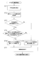
- FIG. 3 is a flowchart showing activation control.
- the control unit 19 detects the outside air temperatures Toa and Tob, and acquires the operation loads of the indoor units 3a to 3d.
- the operating load Qr of the indoor units 3a to 3d is the temperature difference between the indoor temperature Tra to Trd in the indoor unit starting the cooling operation and the target indoor temperature Trat to Trdt as its target temperature, the rated capacity of the indoor unit, etc. In the case where a plurality of indoor units start the cooling operation, it is the total value of the operating loads of these indoor units.
- step ST3 the control unit 19 determines whether the outside air temperatures Toa and Tob are equal to or higher than a predetermined temperature Tox.
- a predetermined temperature Tox it is conceivable to use a specific outside air temperature out of the outside air temperatures Toa, Tob, or to use an average value of the outside air temperatures Toa, Tob, etc.
- the highest temperature value is used among the outside air temperatures Toa, Tob
- the determination in step ST3 is to determine whether or not there is a possibility of high pressure abnormality, and in order to make this determination on the safe side, the variation of the detection values of the outside air temperature sensors 29a and 29b is taken into consideration. It is preferable to use the outside air temperature which shows the highest temperature value.
- the predetermined temperature Tox is an upper limit temperature value that can be determined that there is no risk of occurrence of high pressure abnormality without restricting the outdoor units 2a and 2b activated at the start of operation, for example, 40 to 45 ° C. Set to a high temperature.
- the control unit 19 determines whether the operation load Qr of the indoor units 3a to 3d is equal to or less than a predetermined ratio rQm with respect to the total value Qo of rated capacities of the outdoor units 2a and 2b.
- the rated capacity referred to here means a value equivalent to the nominal capacity described in the product catalog or instruction manual of the outdoor unit 2a, 2b.
- step ST3 the control unit 19 does not set the outside air temperatures Toa and Tob above the predetermined temperature Tox or in step ST4, the operating load Qr of the indoor units 3a to 3d is the rated capacity of the outdoor units 2a and 2b.
- the control unit 19 determines that the outside air temperatures Toa and Tob are not high or the operation load Qr of the indoor units 3a to 3d is not small when the predetermined ratio rQm is not equal to or less than the total value Qo of In step ST5, start control is performed without limiting the outdoor units 2a and 2b to be started.
- step ST3 or step ST4 when the conditions of step ST3 or step ST4 are not satisfied, it is determined that there is no possibility of high pressure abnormality, and the outdoor units 2a and 2b are activated without limitation.
- the control unit 19 activates the compressors 21a and 21b of all the outdoor units 2a and 2b.
- the compressors 21a and 21b at this time are started at the starting rotational speeds Nas and Nbs.
- the starting rotational speeds Nas and Nbs are low rotational speeds near the minimum rotational speeds Nam and Nbm.
- step ST3 the outside air temperatures Toa and Tob are equal to or higher than the predetermined temperature Tox
- step ST4 the operating load Qr of the indoor units 3a to 3d is equal to the total value Qo of the rated capacities of the outdoor units 2a and 2b. If the ratio is lower than the predetermined ratio rQm, the control unit 19 determines that the outside air temperatures Toa and Tob are high and the operation load Qr of the indoor units 3a to 3d is small, and in step ST6 Activation control is performed by limiting the outdoor units 2a and 2b to be activated.
- step ST3 and step ST4 when the conditions of step ST3 and step ST4 are satisfied, it is determined that there is a possibility of high pressure abnormality, and only one of the outdoor units 2a and 2b is activated. Specifically, the control unit 19 activates only the compressor 21a of the outdoor unit 2a or only the compressor 21b of the outdoor unit 2b. At this time, the compressor 21a or the compressor 21b is started at the starting rotation speed Nas or the starting rotation speed Nbs (the starting rotation speed Nas, Nbs is the minimum rotation speed Nam, a low rotation speed near Nbm) as in step ST5. Be done.
- step ST7 After performing the activation control of step ST5 or step ST6, the control unit 19 ends the activation control (step ST7), and shifts to the normal control.
- the number of compressors to be started can be limited to a small number under conditions where there is a risk of high pressure abnormality, and the occurrence of high pressure abnormality during start control can be suppressed.
- control unit 19 determines whether the outside air temperatures Toa and Tob are high depending on whether the outside air temperatures Toa and Tob are equal to or higher than a predetermined value Tox. Therefore, it can be clearly determined whether the outside air temperatures Toa and Tob are high.
- the control unit 19 determines whether the indoor unit 3a to 3d during the start-up control has an operating load Qr equal to or less than a predetermined ratio rQm with respect to the total value Qo of rated capacities of the outdoor units 2a and 2b. It is determined whether the operating load Qr of the units 3a to 3d is small. Therefore, it can be clearly determined whether the operating load Qr of the indoor units 3a to 3d is small.
- the operating load Qr of the indoor units 3a to 3d at the time of start control is the total value of the operating loads of the indoor units 3a to 3d.
- the outdoor units 2a and 2b respectively have the outside air temperature sensors 29a and 29b for detecting the outside air temperatures Toa and Tob, and the control unit 19 detects the outside air temperature sensors 29a and 29b at the time of activation control.
- the highest of the outside air temperatures Toa and Tob is used to determine whether the outside air temperatures Toa and Tob are high. Therefore, it is possible to suppress the occurrence of the high voltage abnormality at the time of the start control by considering the variation of the detected values of the outside air temperatures Toa and Tob in the outdoor units 2a and 2b on the safety side.
- each outdoor unit has a single compressor (that is, the outdoor unit 2a has a single compressor 21a and the outdoor unit 2b has a single compressor 21b).
- the present invention is not limited to this, and the outdoor unit may be configured to have a plurality of compressors.
- the outdoor unit 2a has a plurality of (here, two) compressors 21a
- the outdoor unit 2b has a plurality of (here, two) compressors 21b. It may be
- step ST6 One outdoor unit (here, the outdoor unit 2a or the outdoor unit 2b) starts up one of the plurality of compressors. That is, one of the plurality of compressors 21a of the outdoor unit 2a or one of the plurality of compressors 21b of the outdoor unit 2b is started.
- control unit 19 determines that the outside air temperatures Toa and Tob are not high or the operation load Qr of the indoor units 3a to 3d is not small in steps ST3 and ST4, all the outdoor units in step ST5 (Here, for the outdoor unit 2a and the outdoor unit 2b), one compressor among the plurality of compressors is started. That is, one of the plurality of compressors 21a of the outdoor unit 2a and one of the plurality of compressors 21b of the outdoor unit 2b are activated.
- the number of compressors to be started is limited to one under the condition that there is a possibility of high pressure abnormality, and high pressure abnormality occurs during start control. Can be suppressed.
- step ST6 when the control unit 19 determines that the outside air temperatures Toa and Tob are high and the operation load Qr of the indoor units 3a to 3d is small in steps ST3 and ST4 at the time of activation control.
- step ST6 one of the outdoor units 2a and 2b is activated.
- the outdoor unit activated in step ST6 is fixed, one of the outdoor units 2a and 2b is preferentially activated, and the outdoor units 2a and 2b are not used evenly.
- control unit 19 determines that the outside air temperatures Toa and Tob are high and the operation load Qr of the indoor units 3a to 3d is small in steps ST3 and ST4 at the time of start control, in step ST6.
- One outdoor unit for starting the compressor is rotated each time the operation of the air conditioner 1 is started.
- the compressor to be started can not be fixed to a specific compressor under the condition that there is a possibility of high pressure abnormality, and the compressors 21a and 21b of each outdoor unit 2a and 2b can be used equally. .
- the air conditioner 1 performing the cooling operation has been described as an example, the present invention is not limited to this and has a four-way switching valve or the like for switching the flow of the refrigerant in the refrigerant circuit 10 Therefore, the air conditioner may be capable of switching between the cooling operation and the heating operation.
- the present disclosure is widely applicable to an air conditioner having a plurality of outdoor units.
Landscapes
- Engineering & Computer Science (AREA)
- Mechanical Engineering (AREA)
- General Engineering & Computer Science (AREA)
- Physics & Mathematics (AREA)
- Chemical & Material Sciences (AREA)
- Combustion & Propulsion (AREA)
- Thermal Sciences (AREA)
- Fuzzy Systems (AREA)
- Mathematical Physics (AREA)
- Signal Processing (AREA)
- Air Conditioning Control Device (AREA)
Abstract
L'invention concerne un dispositif de climatisation (1) qui comprend: un circuit de fluide frigorigène (10) constitué par des compresseurs (21a, 21b), des radiateurs (23a, 23b), des détendeurs (31a-31d) et des évaporateurs (32a-32d) qui y sont connectés; et une unité de commande (19) qui commande les compresseurs (21a, 21b). L'unité de commande (19) effectue: une commande de démarrage impliquant le démarrage des compresseurs (21a, 21b), lorsque le fonctionnement du dispositif de climatisation (1) est démarrée; et une commande normale, une fois que la commande de démarrage a été achevée, la capacité de fonctionnement des compresseurs (21a, 21b) étant commandée en fonction de la charge de fonctionnement d'unités internes (3a-3d). Lorsque l'unité de commande (19) détermine, pendant la commande de démarrage, que la température d'air externe est élevée et que la charge de fonctionnement sur les unités internes (3a-3d) est faible, seul un compresseur d'unité externe est démarré.
Priority Applications (1)
| Application Number | Priority Date | Filing Date | Title |
|---|---|---|---|
| PCT/JP2017/039977 WO2019087400A1 (fr) | 2017-11-06 | 2017-11-06 | Dispositif de climatisation |
Applications Claiming Priority (1)
| Application Number | Priority Date | Filing Date | Title |
|---|---|---|---|
| PCT/JP2017/039977 WO2019087400A1 (fr) | 2017-11-06 | 2017-11-06 | Dispositif de climatisation |
Publications (1)
| Publication Number | Publication Date |
|---|---|
| WO2019087400A1 true WO2019087400A1 (fr) | 2019-05-09 |
Family
ID=66331388
Family Applications (1)
| Application Number | Title | Priority Date | Filing Date |
|---|---|---|---|
| PCT/JP2017/039977 Ceased WO2019087400A1 (fr) | 2017-11-06 | 2017-11-06 | Dispositif de climatisation |
Country Status (1)
| Country | Link |
|---|---|
| WO (1) | WO2019087400A1 (fr) |
Cited By (1)
| Publication number | Priority date | Publication date | Assignee | Title |
|---|---|---|---|---|
| CN111981642A (zh) * | 2019-05-21 | 2020-11-24 | 青岛海尔空调电子有限公司 | 热泵空调系统模块机组的能量调节控制方法 |
Citations (5)
| Publication number | Priority date | Publication date | Assignee | Title |
|---|---|---|---|---|
| JP2003343898A (ja) * | 2002-05-23 | 2003-12-03 | Toshiba Kyaria Kk | 空気調和機 |
| JP2004360966A (ja) * | 2003-06-03 | 2004-12-24 | Toshiba Kyaria Kk | 空気調和機 |
| JP2006046782A (ja) * | 2004-08-04 | 2006-02-16 | Samsung Electronics Co Ltd | 空気調和機及び空気調和機の運転方法 |
| JP2010065958A (ja) * | 2008-09-12 | 2010-03-25 | Hitachi Appliances Inc | 空気調和装置 |
| JP2011202888A (ja) * | 2010-03-25 | 2011-10-13 | Daikin Industries Ltd | 空気調和装置 |
-
2017
- 2017-11-06 WO PCT/JP2017/039977 patent/WO2019087400A1/fr not_active Ceased
Patent Citations (5)
| Publication number | Priority date | Publication date | Assignee | Title |
|---|---|---|---|---|
| JP2003343898A (ja) * | 2002-05-23 | 2003-12-03 | Toshiba Kyaria Kk | 空気調和機 |
| JP2004360966A (ja) * | 2003-06-03 | 2004-12-24 | Toshiba Kyaria Kk | 空気調和機 |
| JP2006046782A (ja) * | 2004-08-04 | 2006-02-16 | Samsung Electronics Co Ltd | 空気調和機及び空気調和機の運転方法 |
| JP2010065958A (ja) * | 2008-09-12 | 2010-03-25 | Hitachi Appliances Inc | 空気調和装置 |
| JP2011202888A (ja) * | 2010-03-25 | 2011-10-13 | Daikin Industries Ltd | 空気調和装置 |
Cited By (2)
| Publication number | Priority date | Publication date | Assignee | Title |
|---|---|---|---|---|
| CN111981642A (zh) * | 2019-05-21 | 2020-11-24 | 青岛海尔空调电子有限公司 | 热泵空调系统模块机组的能量调节控制方法 |
| CN111981642B (zh) * | 2019-05-21 | 2022-01-25 | 青岛海尔空调电子有限公司 | 热泵空调系统模块机组的能量调节控制方法 |
Similar Documents
| Publication | Publication Date | Title |
|---|---|---|
| US11867413B2 (en) | HVAC unit with hot gas reheat | |
| CN104718414B (zh) | 空调装置 | |
| US12181168B2 (en) | Air conditioner and control method thereof | |
| JP5300806B2 (ja) | ヒートポンプ装置 | |
| CN104755849B (zh) | 空调装置 | |
| CN107003029B (zh) | 空调装置 | |
| CN105940275B (zh) | 空调装置 | |
| JP6007965B2 (ja) | 空気調和装置 | |
| WO2019087400A1 (fr) | Dispositif de climatisation | |
| WO2019087401A1 (fr) | Dispositif de conditionnement d'air | |
| WO2013172196A1 (fr) | Appareil de conditionnement d'air | |
| JP6353355B2 (ja) | 空気調和装置 | |
| JP2023066634A (ja) | 冷凍サイクル装置 | |
| JP6507598B2 (ja) | 空調システム | |
| JP6519098B2 (ja) | 空気調和装置 | |
| JP5772665B2 (ja) | ヒートポンプ式給湯装置 | |
| WO2023105605A1 (fr) | Dispositif à cycle de réfrigération et procédé de commande |
Legal Events
| Date | Code | Title | Description |
|---|---|---|---|
| 121 | Ep: the epo has been informed by wipo that ep was designated in this application |
Ref document number: 17930931 Country of ref document: EP Kind code of ref document: A1 |
|
| NENP | Non-entry into the national phase |
Ref country code: DE |
|
| 122 | Ep: pct application non-entry in european phase |
Ref document number: 17930931 Country of ref document: EP Kind code of ref document: A1 |
|
| NENP | Non-entry into the national phase |
Ref country code: JP |