WO2019087637A1 - 打込機 - Google Patents
打込機 Download PDFInfo
- Publication number
- WO2019087637A1 WO2019087637A1 PCT/JP2018/036307 JP2018036307W WO2019087637A1 WO 2019087637 A1 WO2019087637 A1 WO 2019087637A1 JP 2018036307 W JP2018036307 W JP 2018036307W WO 2019087637 A1 WO2019087637 A1 WO 2019087637A1
- Authority
- WO
- WIPO (PCT)
- Prior art keywords
- movable member
- weight
- driving machine
- state
- dead center
- Prior art date
- Legal status (The legal status is an assumption and is not a legal conclusion. Google has not performed a legal analysis and makes no representation as to the accuracy of the status listed.)
- Ceased
Links
Images






Classifications
-
- B—PERFORMING OPERATIONS; TRANSPORTING
- B25—HAND TOOLS; PORTABLE POWER-DRIVEN TOOLS; MANIPULATORS
- B25C—HAND-HELD NAILING OR STAPLING TOOLS; MANUALLY OPERATED PORTABLE STAPLING TOOLS
- B25C5/00—Manually operated portable stapling tools; Hand-held power-operated stapling tools; Staple feeding devices therefor
- B25C5/10—Driving means
- B25C5/15—Driving means operated by electric power
-
- B—PERFORMING OPERATIONS; TRANSPORTING
- B25—HAND TOOLS; PORTABLE POWER-DRIVEN TOOLS; MANIPULATORS
- B25C—HAND-HELD NAILING OR STAPLING TOOLS; MANUALLY OPERATED PORTABLE STAPLING TOOLS
- B25C1/00—Hand-held nailing tools; Nail feeding devices
- B25C1/008—Safety devices
-
- B—PERFORMING OPERATIONS; TRANSPORTING
- B25—HAND TOOLS; PORTABLE POWER-DRIVEN TOOLS; MANIPULATORS
- B25C—HAND-HELD NAILING OR STAPLING TOOLS; MANUALLY OPERATED PORTABLE STAPLING TOOLS
- B25C1/00—Hand-held nailing tools; Nail feeding devices
- B25C1/06—Hand-held nailing tools; Nail feeding devices operated by electric power
Definitions
- the present invention relates to a driving machine provided with a first movable member operable in a first direction and a second direction.
- Patent Document 1 describes a driving machine having a first movable member operable in a first direction and a second direction.
- the driving machine described in Patent Document 1 includes a housing, a motor, a plunger, a weight, a coil spring, a drive mechanism, and a nose portion.
- the plunger is actuable downward as a first direction and upward as a second direction.
- a rod is attached to the plunger.
- the plunger and the rod constitute a first movable member.
- the weights are actuable up and down.
- the motor and the drive mechanism are provided in the housing.
- the drive mechanism has a drive gear, a first pulley and a second pulley.
- the drive gear is coupled to the motor.
- the first pulley meshes with the drive gear and the second pulley.
- the first pulley has a plurality of roller cams, and the second pulley has a plurality of roller cams.
- the housing has a handle portion, and the battery is removably attached to the handle portion.
- a trigger is provided on the handle.
- the plunger When the motor is at rest, the plunger is at bottom dead center and the weight is at top dead center.
- the battery supplies power to the motor and the motor rotates.
- the rotational force of the motor is transmitted to the first pulley via the drive gear.
- the rotational force of the first pulley is transmitted to the second pulley.
- the roller cam of the first pulley engages with the plunger, the plunger operates from the bottom dead center toward the top dead center.
- the roller cam of the second pulley engages with the weight, the weight operates from top dead center to bottom dead center.
- the coil spring is compressed by the operation of the plunger and the weight, and the coil spring stores elastic energy.
- the plunger When the roller cam of the first pulley is released from the plunger, the plunger starts its downward operation by the elastic energy of the coil spring. When the roller cam of the second pulley is released from the weight, the weight starts the upward operation by the elastic energy of the coil spring.
- the plunger When the plunger is actuated downward, the rod strikes the nail in the nose and the nail is driven into the workpiece. After the rod strikes the nail, the plunger reaches bottom dead center. Also, the weight reaches the top dead center.
- the inventor of the present application has determined that the timing at which the first movable member starts to operate in the first direction due to a manufacturing error of the elements constituting the drive mechanism of the driving machine or a gap formed between the elements; It has been recognized that there is a possibility that the feel of the impact may change due to the incompatibility of the relationship with the timing at which the movable member starts to operate in the second direction.
- the driving machine includes a first movable member operable in a first direction and a second direction opposite to the first direction, and a second movable operable in the first direction and the second direction.
- a driving mechanism having a member, wherein the first movable member is urged in the first direction, and the second movable member is urged in the second direction;
- a first restricting mechanism that prevents and allows the movable member to operate in the first direction;
- a second restricting mechanism that prevents and allows the second movable member to operate in the second direction;
- the second restriction mechanism permits the operation of the second movable member, a first state in which the second movable member is prevented from operating in the second direction, and the second movable member in the second direction
- a third restricting mechanism having a second state for allowing operation; said first movable portion When the third restriction mechanism is held in the first state when the operation in the first direction is blocked, and the first movable member is allowed to operate in the first direction and operated The third restriction mechanism switches from
- the driving machine can easily stabilize the relationship between the timing at which the first movable member starts to operate in the first direction and the timing at which the second movable member starts to operate in the second direction. Ring improves.
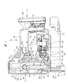
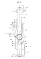
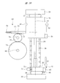
- FIG. 1 is a side cross-sectional view of a driving machine corresponding to some embodiments included in the present invention. It is a perspective view of the striking part provided in the driving machine of FIG. 1, a weight, and a drive mechanism. It is a side view of the striking part provided in the driving machine of FIG. 1, a weight, and a drive mechanism. It is a rear view of the striking part provided in the driving machine of FIG. 1, and a weight. It is a block diagram which shows the control system of the driving machine of FIG. In Embodiment 1 of a driving machine, it is a side view in the state where a striking part is located in a bottom dead center and a weight is located in a top dead center.
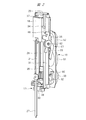
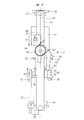
- Embodiment 1 of a driving machine it is a side view in the state where a striking part raises from a bottom dead center and a weight falls from a top dead center. It is a side view in the state where a striking part raises further from the position shown in FIG. 7, and a weight falls further from the position shown in FIG.
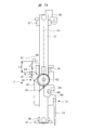
- FIG. 9 is a side view of a state in which the striking part further rises from the position shown in FIG. 8 and the weight has reached the bottom dead center.
- FIG. 10 is a side view of a state in which the striking part further rises from the position shown in FIG. 9 and the weight is stopped at the bottom dead center.
- FIG. 1 It is a side view of a state where a striking part has reached top dead center and a weight has stopped at the bottom dead center. It is a side view in the state where a striking part descends from a top dead center, and a weight has risen from a bottom dead center. It is a time chart which shows the operation example of the plunger of an impact part, and a weight.
- Embodiment 2 of a driving machine it is a side view in the state where a striking part is located in a bottom dead center and a weight is located in a top dead center.
- a striking part raises from a bottom dead center and it is a side view in the state where a weight falls from a top dead center.
- FIG. 1 It is a side view of a state where a striking part has reached top dead center and a weight has stopped at the bottom dead center. It is a side view in the state where a striking part descends from a top dead center, and a weight has risen from a bottom dead center.
- FIG. 16 is a side view of a state where the striking part further rises from the position shown in FIG. 15 and the weight further descends from the position shown in FIG. 15.
- FIG. 17 is a side view of a state in which the weight is further lowered from the position shown in FIG. 16 and the striking portion has reached top dead center.
- FIG. 18 is a side view of a state in which the weight is further lowered from the position shown in FIG. 17 and the striking portion is stopped at the top dead center. It is a side view of a state where a weight reaches bottom dead center and a strike part has stopped at top dead center. It is a side view in the state where a striking part descends from a top dead center, and a weight has risen from a bottom dead center.
- Embodiment 3 of a driving machine it is a side view in the state where a striking part is located in a bottom dead center and a weight is located in a top dead center.
- FIG. 22 is a side view of a state in which the striking part rises from the bottom dead center shown in FIG. 21 and the weight descends from the top dead center shown in FIG. 21. It is a side view of a state where a strike part starts descent
- An exemplary embodiment of the present invention includes a first movable member operable in a first direction and a second direction, and a second movable member operable in a first direction and a second direction.
- a biasing mechanism biasing the first movable member in the first direction and biasing the second movable member in the second direction; and preventing and allowing the first movable member to operate in the first direction
- a first restriction mechanism, a second restriction mechanism that blocks and allows the second movable member to operate in the second direction, a first state that prevents the second movable member from operating in the second direction, and a second state And a second state that allows the movable member to operate in the second direction. Then, when the first movable member operates in the first direction, the third restricting mechanism is switched from the first state to the second state.
- a driving machine 10 shown in FIG. 1 has a housing 11, a striking portion 12, a magazine 13, an electric motor 14, a conversion mechanism 15, a control board 16, a battery pack 17, and a weight 18.
- the housing 11 has a cylindrical main body 19, a handle 20 connected to the main body 19, and a motor case 21 connected to the main body 19.
- the mounting portion 22 is connected to the handle 20 and the motor case 21.
- the injection unit 23 is provided outside the main body unit 19, and the injection unit 23 is fixed to the main body unit 19.
- the injection unit 23 has an injection passage 24. The user can hold the handle 20 by hand and press the tip of the injection unit 23 against the workpiece W1.
- the magazine 13 is supported by the motor case 21 and the ejection unit 23.
- the motor case 21 is disposed between the handle 20 and the magazine 13 in the direction of the axis A1.
- the magazine 13 accommodates a plurality of fasteners 25.
- the fastener 25 includes a nail, and the material of the fastener 25 includes metal, non-ferrous metal, and steel.
- the fasteners 25 are connected to each other by connection elements.
- the connection element may be either a wire, an adhesive or a resin.
- the fastener 25 is rod-shaped.
- the magazine 13 has a feeder. The feeder sends the stopper 25 accommodated in the magazine 13 to the ejection path 24.
- the striking portion 12 is provided across the inside and the outside of the main body portion 19.
- the striking portion 12 has a plunger 26 disposed in the main body portion 19 and a driver blade 27 fixed to the plunger 26.
- the plunger 26 is made of metal or synthetic resin.
- the plunger 26 has a contact portion 32.
- the chamfered portion 33 is formed on the outer surface of the contact portion 32.
- the chamfered portion 33 is curved.
- the driver blade 27 is made of metal.
- a guide shaft 28 is provided in the main body 19.
- the axis A1 passes through the center of the guide shaft 28.
- the material of the guide shaft 28 may be any of metal, nonferrous metal and steel.
- the top holder 29 and the bottom holder 30 are fixedly provided in the housing 11.
- the material of the top holder 29 and the bottom holder 30 may be any of metal, non-ferrous metal and steel.
- the guide shaft 28 is fixed to the top holder 29 and the bottom holder 30.
- a guide bar 31 is provided in the main body 19. Two guide bars 31 are provided, and the two guide bars 31 are fixed to the top holder 29 and the bottom holder 30.
- the two guide bars 31 are both plate-shaped and arranged in parallel to the axis A1.
- the plunger 26 is attached to the outer peripheral surface of the guide shaft 28, and the plunger 26 is operable along the guide shaft 28 in the direction of the axis A 1.
- the guide shaft 28 radially positions the plunger 26 about the axis A1.
- the guide bar 31 positions the plunger 26 circumferentially around the axis A1.
- the driver blade 27 is operable with the plunger 26 parallel to the axis A1.
- the driver blade 27 is operable in the injection path 24.
- the weight 18 suppresses the reaction that the housing 11 receives.
- the material of the weight 18 may be any of metal, nonferrous metal, steel, and ceramic.
- the weight 18 is attached to the guide shaft 28.
- the weight 18 has a cylindrical shape as an example, and the pin 34 and the weight arm portion 35 are provided on the weight 18.
- the weight 18 is operable along the guide shaft 28 in the direction of the axis A1.
- the guide shaft 28 positions the weight 18 in the radial direction with respect to the axis A1.
- the guide bar 31 positions the weight 18 in the circumferential direction about the axis A1.
- a spring 36 is disposed within the body portion 19 and the spring 36 is disposed between the plunger 26 and the weight 18 in the direction of the axis A1.
- the spring 36 can use a metal compression coil spring as an example.
- the spring 36 can expand and contract in the direction of the axis A1.
- the first end of the spring 36 in the direction of the axis A1 directly or indirectly contacts the plunger 26.
- the second end of the spring 36 in the direction of the axis A1 directly or indirectly contacts the weight 18.
- the spring 36 receives elastic pressure in the direction of the axis A1 and stores elastic energy.
- the spring 36 is an example of a biasing mechanism that biases the striking portion 12 and the weight 18.
- the plunger 26 receives from the spring 36 a biasing force in the first direction D1 approaching the bottom holder 30 in the direction of the axis A1.
- the weight 18 receives a biasing force in the second direction D2 approaching the top holder 29 in the direction along the axis A1, from the spring 36.
- the first direction D1 and the second direction D2 are opposite to each other, and the first direction D1 and the second direction D2 are parallel to the axis A1.
- the plunger 26 and the weight 18 receive biasing force from a physically identical element, a spring 36.
- a weight bumper 37 and a plunger bumper 38 are provided in the main body 19.
- the weight bumper 37 is disposed between the top holder 29 and the weight 18.
- the plunger bumper 38 is disposed between the bottom holder 30 and the plunger 26.
- the weight bumper 37 and the plunger bumper 38 are both made of synthetic rubber.
- the driving machine 10 shown in FIG. 1 shows an example in which the axis A1 is in parallel with the vertical line.
- the actuation of the striking portion 12 or the plunger 26 or the weight 18 in the first direction D1 is referred to as descent.
- actuation of the striking portion 12 or the plunger 26 or the weight 18 in the second direction D2 is referred to as lifting.
- the striking portion 12 and the weight 18 can be reciprocated in the direction of the axis A1.
- the battery pack 17 shown in FIG. 1 is attachable to and detachable from the mounting portion 22.
- the battery pack 17 has a housing case 39 and a plurality of battery cells housed in the housing case 39.
- the battery cell is a secondary battery capable of charging and discharging, and the battery cell may be any of a lithium ion battery, a nickel hydrogen battery, a lithium ion polymer battery, and a nickel cadmium battery.
- the battery pack 17 is a DC power supply, and the electric power of the battery pack 17 can be supplied to the electric motor 14.
- the control board 16 shown in FIG. 1 is provided in the mounting portion 22, and the controller 40 and the inverter circuit 41 shown in FIG. 5 are provided on the control board 16.
- the controller 40 is a microcomputer having an input port, an output port, an arithmetic processing unit, and a storage unit.
- the inverter circuit 41 has a plurality of switching elements, and the plurality of switching elements can be turned on and off, respectively.
- the controller 40 outputs a signal for controlling the inverter circuit 41.
- An electric circuit is formed between the battery pack 17 and the electric motor 14.
- the inverter circuit 41 is a part of the electrical circuit, and connects and disconnects the electrical circuit.
- the trigger 42 and the trigger switch 43 are provided on the handle 20, and when the user applies an operating force to the trigger 42, the trigger switch 43 is turned on. When the user releases the operating force applied to the trigger 42, the trigger switch 43 is turned off.
- a position detection sensor 44 shown in FIG. 5 is provided in the housing 11. The position detection sensor 44 estimates the positions of the plunger 26 and the weight 18 in the direction of the axis A1, for example, based on the rotation angle of the electric motor 14, and outputs a signal.
- the controller 40 receives the signal of the trigger switch 43 and the signal of the position detection sensor 44, and outputs a signal for controlling the inverter circuit 41.
- the electric motor 14 has a rotor 84 and a stator 45, and a motor shaft 46 is attached to the rotor 84.
- the electric motor 14 rotates the motor shaft 46 when power is supplied from the battery pack 17.
- a reduction gear 47 is disposed in the motor case 21.
- the reduction gear 47 has a plurality of sets of planetary gear mechanisms, an input element 48 and an output element 49.
- the input element 48 is connected to the motor shaft 46.
- the electric motor 14 and the reduction gear 47 are disposed concentrically about the axis B1.
- the driving machine 10 shown in FIG. 1 shows an example in which the angle between the axis A1 and the axis B1 is 90 degrees.
- the conversion mechanism 15 converts the rotational force of the output element into the actuating force of the striking portion 12 and the actuating force of the weight 18.
- the conversion mechanism 15 has a first gear 50, a second gear 51 and a third gear 52.
- the material of the first gear 50, the second gear 51, and the third gear 52 may be any of metal, nonferrous metal, and steel.
- a holder 53 is provided in the housing 11, and the output element 49 is rotatably supported by the holder 53.
- the first gear 50 is fixed to the output element 49.
- the second gear 51 is rotatably supported by the support shaft 54.
- the third gear 52 is rotatably supported by the support shaft 55.
- the support shafts 54 and 55 are attached to the holder 53.
- the first gear 50 is rotatable about the axis B1
- the second gear 51 is rotatable about the axis B2
- the third gear 52 is rotatable about the axis B3.
- the axes B1, B2 and B3 are arranged at intervals in the direction of the axis A1.
- the axis B2 is disposed between the axis B1 and the axis B3.
- the axes B1, B2, B3 are parallel to one another.
- the third gear 52 is disposed between the second gear 51 and the top holder 29 in the direction of the axis A1.
- the first gear 50 is disposed between the second gear 51 and the magazine 13 in the direction of the axis A1.
- the outer diameter of the first gear 50, the outer diameter of the second gear 51, and the outer diameter of the third gear 52 are the same.
- the second gear 51 meshes with the first gear 50 and the third gear 52.
- the cam roller 57 is provided on the first gear 50, the two cam rollers 58 are provided on the second gear 51, and the two cam rollers 59 are provided on the third gear 52. .
- the cam roller 57 can rotate on the first gear 50.
- the two cam rollers 58 are disposed on the same circumference around the axis B2.
- the two cam rollers 58 can rotate independently with respect to the second gear 51.
- the two cam rollers 59 can rotate on the third gear 52 respectively.
- the two cam rollers 59 are disposed on the same circumference around the axis B3.
- the material of the cam rollers 57, 58, 59 may be any of metal, non-ferrous metal and steel.
- the first arm 85 and the second arm 60 are provided on the plunger 26.
- the first arm 85 and the second arm 60 are made of metal.
- the cam roller 57 can engage and release the first arm portion 85.
- the cam roller 58 can engage and release the second arm portion 60.
- the cam roller 59 can be engaged with and released from the weight arm portion 35.
- the latch 61 is attached to the guide bar 31.
- the latch 61 is rotatable relative to the guide bar 31 about the support shaft 62.
- the support shaft 62 is, as an example, located within the arrangement range of the third gear 52 in the direction of the axis A1.
- a metal spring 63 is attached to the latch 61.
- the spring 63 is, for example, a torsion coil spring, and the first end in the winding direction of the spring 63 is engaged with the latch 61, and the second end in the winding direction of the spring 63 is engaged with the guide bar 31 .
- the spring 63 biases the latch 61 clockwise around the support shaft 62.
- a stopper 64 is provided on the latch 61, and when the stopper 64 contacts the guide bar 31, the latch 61 is stopped.
- the latch 61 has an arm 65 and a hook 66. The arm 65 and the hook 66 are disposed apart from the support shaft 62 in the longitudinal direction of the latch 61.
- the hook 66 is located between the top holder 29 and the support shaft 62 in the direction of the axis A1.
- the arm 65 is located between the bottom holder 30 and the support shaft 62 in the direction of the axis A1.
- the hook 66 is capable of contacting and disengaging the pin 34. Specifically, the hooks 66 can engage and release the pins 34.
- the arm 65 can contact and move away from the contact portion 32.
- a chamfer 67 is formed on the outer surface of the arm 65.
- the chamfered portion 67 is curved.
- the latch 61 and the spring 63 constitute a third restricting mechanism 71.
- the controller 40 detects that the trigger switch 43 is off, the controller 40 does not supply power to the electric motor 14 and stops the motor shaft 46.
- the electric motor 14 is stopped, as shown in FIG. 6, the plunger 26 is stopped at a position where it contacts the plunger bumper 38, that is, at the bottom dead center.
- the weight 18 is biased by the elastic force of the spring 36, and stops at the position where it contacts the weight bumper 37, that is, at the top dead center.
- the controller 40 processes the signal of the position detection sensor 44 to estimate the position of the plunger 26 and the weight 18 in the direction of the axis A1.
- the cam rollers 57, 58 are separated from the second arm portion 60.
- the cam roller 59 is separated from the weight arm portion 35.
- the controller 40 When the user presses the tip of the injection unit 23 against the workpiece W1 and the controller 40 detects that the trigger switch 43 is turned on, the controller 40 supplies power to the electric motor 14 to rotate the motor shaft 46 forward.
- the rotational force of the motor shaft 46 is amplified by the reduction gear 47 and transmitted to the first gear 50, and the first gear 50 rotates counterclockwise in FIG.
- cam roller 57 When the cam roller 57 is engaged with the first arm 85 while the first gear 50 and the second gear 51 are rotating, one cam roller 58 is engaged with the second arm 60. Thereafter, the cam roller 57 is released from the first arm portion 85. Further, when one cam roller 58 is engaged with the second arm portion 60, another cam roller 58 is engaged with the second arm portion 60. Then, the cam roller 58 previously engaged with the second arm 60 is released from the second arm 60.
- the weight 18 reaches the bottom dead center and the plunger 26 is further raised. Also, the contact portion 32 is maintained in contact with the arm 65. Further, the third gear 52 is rotated, and the two cam rollers 59 are both released from the weight arm portion 35. However, since the contact portion 32 is in contact with the arm 65, the latch 61 is at rest. That is, as shown in FIG. 11, the hook 66 is engaged with the pin 34, and the weight 18 is at rest.
- the plunger 26 When the plunger 26 is lowered, that is, when the striking portion 12 is lowered, the driver blade 27 strikes the stopper 25 located in the injection path 24. The stopper 25 is driven into the workpiece W1. After the driver blade 27 strikes the stopper 25, the plunger 26 collides with the plunger bumper 38 as shown in FIG. The plunger bumper 38 absorbs part of the kinetic energy of the striking part 12. Also, the weight 18 collides with the weight bumper 37. The weight bumper 37 absorbs part of the kinetic energy of the weight.
- the weight 18 when the striking part 12 operates in the first direction to strike the stopper 25, the weight 18 operates in the second direction opposite to the first direction. For this reason, it is possible to reduce reaction when the striking portion 12 strikes the stopper 25. Therefore, the relationship between the first timing when the plunger 26 starts actuation from top dead center to bottom dead center and the second timing when the weight 18 starts actuation from bottom dead center to top dead center is stabilized. And, it becomes easy to reduce reaction.
- the controller 40 estimates the position of the plunger 26 in the direction of the axis A1, and stops the electric motor 14 before the plunger 26 starts to descend until it collides with the plunger bumper 38. Therefore, the plunger 26 stops at the bottom dead center in contact with the plunger bumper 38, and the weight 18 stops at the top dead center in contact with the weight bumper 37. Then, when the user releases the operating force to the trigger 42 and applies the operating force to the trigger 42 again, the controller 40 rotates the electric motor 14, and the striking unit 12 and the weight 18 operate in the same manner as described above.
- FIG. 13 is a time chart showing an operation example of the plunger 26 and the weight 18.
- the position of the plunger 26 is indicated by a solid line
- the position of the weight 18 is indicated by a broken line.
- the plunger 26 stops at the bottom dead center before time t1
- the weight 18 stops at the top dead center before time t1.
- the plunger 26 starts its operation from the bottom dead center to the top dead center at time t1.
- the weight 18 is also stopped at the top dead center after time t1.
- the weight 18 starts operating from top dead center to bottom dead center at time t2.
- the weight 18 reaches the bottom dead center at time t3, and the weight 18 stops at the bottom dead center after time t3.
- the hook 66 engages with the pin 34 at time t4, and the latch 61 is in a state capable of holding the weight 18.
- the plunger 26 reaches the top dead center at time t5, and the plunger 26 stops at the top dead center after time t5.
- the plunger 26 starts to descend from the top dead center to the bottom dead center at time t6. Since the latch 61 holds the weight 18 at time t6, the weight 18 is also stopped at the bottom dead center after time t6.
- the weight 18 starts operating from the bottom dead center toward the top dead center. Then, the plunger 26 reaches the bottom dead center at time t8, and the weight 18 reaches the top dead center at time t8. The plunger 26 may reach the bottom dead center at time t8, and the weight 18 may reach the top dead center after time t8.
- the latch 61 operates according to the position in the direction of the axis A1 of the plunger 26 which is an element of the striking portion 12, and the plunger 26 operates from top dead center to bottom dead center. The relationship between the first timing to start and the second timing to start the operation from the bottom dead center to the top dead center is determined.
- the conditions of the driving machine 10 include at least one of the following: variations in the shape or size of the elements constituting the conversion mechanism 15; and variations in the assembly state of the elements constituting the conversion mechanism 15.
- the first embodiment of the driving machine 10 adopts either the configuration for increasing the stroke amount of the weight 18 or the configuration for increasing the mass of the weight 18. I did not. Therefore, at least one of the increase in size and the increase in weight of the driving machine 10 can be avoided.
- the first embodiment of the driving machine 10 can change or adjust the timing at which the plunger 26 rises from the bottom dead center by setting the number of cam rollers 57 and the position of the cam roller 57 in the rotation direction of the first gear 50. .
- the embodiment 1 of the driving machine 10 can change or adjust the timing at which the plunger 26 reaches the top dead center.
- the first embodiment of the driving machine 10 can change or adjust the timing at which the plunger 26 descends from the top dead center by setting the number of cam rollers 58 and the position of the cam roller 58 in the rotation direction of the second gear 51. .
- the first embodiment of the driving machine 10 can change or adjust the timing at which the weight 18 descends from the top dead center by setting the number of cam rollers 59 and the position of the cam roller 59 in the rotational direction of the third gear 52. is there.
- the embodiment 1 of the driving machine 10 can change or adjust the timing at which the weight 18 reaches the bottom dead center.
- the timing at which the weight 18 rises from the bottom dead center can be defined as the required time from the timing at which the plunger 26 descends from the top dead center to the timing at which the weight 18 rises from the bottom dead center.
- the required time corresponds to the time from time t6 to time t7 in the time chart of FIG.
- the length L1 of the arm 65 is a value at which the contact portion 32 blocks the operation of the latch 61 when the arm 65 and the contact portion 32 are in contact with each other. For example, as the length L1 of the arm 65 is set relatively short, the required time becomes relatively short.
- a second embodiment of a driving machine having a third restricting mechanism will be described with reference to FIG.
- a pin 68 is provided on the plunger 26.
- the pin 34 shown in FIG. 6 is not provided to the weight 18 of FIG.
- the contact portion 69 is provided on the weight 18, and the chamfered portion 70 is formed on the outer surface of the contact portion 69.
- the chamfer 70 is curved.
- the contact portion 32 shown in FIG. 6 is not provided on the plunger 26 of FIG.
- the support shaft 62 supporting the latch 61 is disposed at a position closer to the bottom holder 30 than the middle between the top holder 29 and the bottom holder 30 in the direction of the axis A1.
- the arm 65 of the latch 61 is located between the top holder 29 and the support shaft 62 in the direction of the axis A1.
- the hook 66 of the latch 61 is located between the bottom holder 30 and the support shaft 62 in the direction of the axis A1.
- the latch 61 is biased clockwise about the support shaft 62 in FIG.
- the plunger 26, the weight 18 and the latch 61 shown in FIG. 14 can be provided in the driving machine 10 shown in FIG. 1, and the driving machine 10 is the second embodiment.
- the cam roller 57 of the first gear 50 shown in FIG. 4 can be engaged with and released from the first arm portion 85, and the cam roller 58 of the second gear 51 can be used as the second arm portion 60. It can be engaged and released.
- the cam roller 59 of the third gear 52 can be engaged with and released from the weight arm portion 35.
- Embodiment 2 of the driving machine 10 The usage example of Embodiment 2 of the driving machine 10 is demonstrated.
- the electric motor 14 shown in FIG. 1 When the electric motor 14 shown in FIG. 1 is stopped, it stops at the bottom dead center as shown in FIG. 14, and the weight 18 stops at the top dead center. Further, the stopper 64 is in contact with the guide bar 31 and the latch 61 is stopped. Also, the arm 65 is separated from the contact portion 69, and the hook 66 is released from the pin 68.
- the weight 18 When the electric motor 14 shown in FIG. 1 is rotated, the weight 18 operates in the second direction D3 against the biasing force of the spring 36 as shown in FIG. That is, the weight 18 descends. Further, similarly to the first embodiment of the driving machine 10, the plunger 26 shown in FIG. 15 operates in the first direction D4. That is, the plunger 26 ascends.
- the first direction D4 and the second direction D3 are parallel to the axis A1.
- the plunger 26 reaches top dead center and the weight 18 further descends. Also, the contact portion 69 is maintained in contact with the arm 65. Further, the cam roller 58 shown in FIG. 4 is released from the second arm portion 60 shown in FIG. Then, the rotational force of the electric motor 14 shown in FIG. 1 is not transmitted to the plunger 26 shown in FIG. However, the contact portion 69 contacts the arm 65, and the contact portion 69 stops the latch 61. That is, as shown in FIG. 19, the hook 66 remains engaged with the pin 68, and the plunger 26 is at rest.
- the latch 61 operates clockwise by the biasing force of the spring 63. Then, the hook 66 is released from the pin 68, and the plunger 26 is lowered from the top dead center by the biasing force of the spring 36.
- the driver blade 27 strikes the stopper 25 located in the injection path 24. After the driver blade 27 strikes the stopper 25, the plunger 26 collides with the plunger bumper 38 as shown in FIG. Also, the weight 18 collides with the weight bumper 37. Also in the second embodiment of the driving machine 10, it is possible to reduce the reaction when the striking portion 12 strikes the stopper 25.
- the position of the plunger 26 in the second embodiment of the driving machine 10 is indicated by a broken line, and the position of the weight 18 is indicated by a solid line.
- the position of the plunger 26 in the second embodiment of the driving machine 10 corresponds to the position of the weight 18 in the first embodiment of the driving machine 10, and the position of the weight 18 in the second embodiment is the position of the plunger 26 in the first embodiment.
- Embodiment 2 of the driving machine 10 can acquire the same effect as Embodiment 1 of the driving machine 10.
- the second embodiment of the driving machine 10 can change or adjust the timing at which the weight 18 descends from the top dead center by setting the number of cam rollers 59 and the position of the cam roller 59 in the rotation direction of the third gear 52. .
- the embodiment 2 of the driving machine 10 can change or adjust the timing at which the weight 18 reaches the bottom dead center by setting the diameter of the circumscribed circle of the cam roller 59 in the radial direction of the third gear 52.
- the second embodiment of the driving machine 10 can change or adjust the timing at which the plunger 26 ascends from the bottom dead center by setting the number of cam rollers 57 and the position of the cam roller 57 in the rotation direction of the first gear 50. .
- the embodiment 2 of the driving machine 10 can change or adjust the timing at which the plunger 26 reaches the top dead center by setting the diameter of the circumscribed circle of the cam roller 57 in the radial direction of the first gear 50.
- Embodiment 2 of the driving machine 10 can change or adjust the timing at which the plunger 26 descends from the top dead center by setting the length L2 in the direction of the axis A1 of the arm 65 as shown in FIG. is there.
- the timing at which the plunger 26 descends from the top dead center can be defined as the required time from the timing at which the weight 18 rises from the bottom dead center to the timing at which the plunger 26 descends from the top dead center.
- the required time corresponds to the time from time t6 to time t7 in the time chart of FIG.
- the length L2 of the arm 65 is a value that can prevent the contact portion 69 from operating the latch 61 when the arm 65 and the contact portion 69 are in contact with each other. For example, as the length L2 of the arm 65 is set relatively short, the required time becomes relatively short.
- FIG. A pressing member 72 is attached to the plunger 26.
- the pressing member 72 is a metal pin as an example.
- a spring 73 is attached to the plunger 26.
- the spring 73 is a metal compression spring as an example, and the spring 73 biases the pressing member 72 in a direction intersecting the axis A1.
- the pressing member 72 is biased by the spring 73, contacts the stopper, and stops at a position.
- the tip end portion of the pressing member 72 has a sufficient coefficient of friction to convert the actuating force of the pressing member 72 into a driving force of the gear 76, that is, a rotational force, when in contact with the gear 76.
- the configuration for setting the coefficient of friction of the tip of the pressing member 72 in this manner includes selection of the material of at least a part of the pressing member 72 and selection of the shape of the tip of the pressing member 72.
- One example of the selection of the material of at least a part of the pressing member 72 is to make at least a part of the pressing member 72 made of synthetic rubber.
- One example of the selection of the shape of the tip of the pressing member 72 includes a convex portion provided on the tip of the pressing member 72 and a rack-like uneven portion.
- the movable member 74 and the gears 75 and 76 are provided in the housing 11 shown in FIG.
- the movable member 74 is operable in the direction of an axis C1 intersecting with the axis A1.
- the movable member 74 is a metal pin as an example.
- a guide member which supports the movable member 74 in the direction of the axis C1 is provided in the housing 11.
- the movable member 74 has a rack 77 disposed along the direction of the axis C1.
- the outer diameter of the gear 76 is larger than the outer diameter of the gear 75, and the gear 75 and the gear 76 mesh with each other.
- the gear 76 has no teeth on a part of the outer peripheral surface that transmits the driving force by the frictional force when contacting the pressing member 72. Moreover, it is also possible to provide a tooth engaged with the convex portion and the concave and convex portion of the pressing member 72 in a portion of the gear 76 in contact with the tip end portion of the pressing member 72.
- the gear 75 meshes with the rack 77.
- the gear 75 is rotatable about the support shaft 79, and the gear 76 is rotatable about the support shaft 80.
- a spring 78 is provided in the housing 11 and biases the movable member 74 towards the weight 18 in the direction of the axis C1.
- the spring 78 is a metal compression spring as an example.
- the weight 18 is provided with an engaging portion 81.
- the engaging portion 81 is, for example, a recess provided on the outer surface of the weight 18.
- the tip of the movable member 74 is engageable with and disengageable from the engagement portion 81.
- the movable member 74, the gears 75 and 76, and the spring 78 constitute a third restriction mechanism 82.
- the third restriction mechanism 82, the weight 18 and the plunger 26 shown in FIG. 21 can be provided in the driving machine 10 shown in FIG. 1, and the driving machine 10 is the third embodiment.
- the plunger 26 shown in FIG. 21 has a second arm 60.
- the cam roller 57 shown in FIG. 4 is engageable with and releasable from the first arm 85 shown in FIG. 21, and the cam roller 58 is engageable with and releasable from the second arm 60.
- the weight 18 shown in FIG. 21 has a weight arm portion 35.
- the cam roller 59 shown in FIG. 4 can be engaged with and released from the weight arm portion 35 shown in FIG.
- Embodiment 3 of the driving machine 10 is demonstrated.
- the plunger 26 is biased by the spring 36 and stopped at the bottom dead center as shown in FIG.
- the pressing member 72 is separated from the gear 76.
- the weight 18 is biased by the spring 36 and stops at the top dead center. Since the gears 75 and 76 are stopped, the movable member 74 is stopped at a predetermined position in the direction of the axis C1. The movable member 74 is released from the engaging portion 81.
- the downward force of the plunger 26 causes the gear 76 to rotate clockwise by a predetermined angle in FIG.
- the gear 75 rotates counterclockwise in FIG. 23 by a predetermined angle. Therefore, the movable member 74 separates from the weight 18 against the force of the spring 78.
- the pressing member 72 separates from the gear 76, the gears 76 and 75 stop, and the movable member 74 stops at a predetermined position.
- the gears 75 and 76 and the movable member 74 operate according to the position of the plunger 26 in the direction of the axis A1, and the first timing at which the plunger 26 starts to descend from top dead center; The relationship with the second timing at which the weight 18 starts to rise from the bottom dead center is determined. Therefore, the third embodiment of the driving machine 10 can obtain the same effect as the first embodiment of the driving machine 10.
- the third embodiment of the driving machine 10 can change or adjust the timing at which the plunger 26 ascends from the bottom dead center on the same principle as the first embodiment of the driving machine 10.
- the third embodiment of the driving machine 10 can change or adjust the timing at which the plunger 26 reaches the top dead center by the same principle as the first embodiment of the driving machine 10.
- the third embodiment of the driving machine 10 can change or adjust the timing at which the plunger 26 descends from the top dead center on the same principle as the first embodiment of the driving machine 10.
- the third embodiment of the driving machine 10 can change or adjust the timing at which the weight 18 descends from the top dead center on the same principle as the first embodiment of the driving machine 10.
- the third embodiment of the driving machine 10 can change or adjust the timing at which the weight 18 reaches the bottom dead center by the same principle as the first embodiment of the driving machine 10.
- the rotation angle of the gear 76 with respect to the amount of operation of the plunger 26, the transmission ratio when transmitting power from the gear 76 to the gear 75, and the movable member 74 with respect to the rotation angle of the gear 75 can be changed or adjusted based on the amount of operation when the weight 18 moves away from the weight 18.
- the timing at which the weight 18 rises from the bottom dead center can be defined as the required time from the timing at which the plunger 26 descends from the top dead center to the timing at which the weight 18 rises from the bottom dead center.
- the function of the movable member 74 to hold the weight 18 at the bottom dead center becomes easy to be released from the engaging portion 81 as the amount of operation when the movable member 74 moves away from the weight 18 is relatively large. Is more likely to be released.
- the required time becomes shorter as the rotation angle of the gear 76 relative to the amount of actuation of the plunger 26 is relatively larger.
- the required time is shorter as the operation amount of the movable member 74 relative to the change amount of the rotation angle of the gear 75 is relatively larger.
- the required time is shorter as the gear ratio between the gear 76 and the gear 75 is relatively smaller.
- the driving machine 10 is an example of a driving machine.
- the first direction D1 is an example of a first direction
- the second direction D2 is an example of a second direction.
- the striking part 12 is an example of a first movable member
- the weight 18 is an example of a second movable member.
- the spring 36 is an example of a biasing mechanism.
- the second gear 51 and the cam roller 58 are an example of a first restricting mechanism
- the third gear 52 and the cam roller 59 are an example of a second restricting mechanism.
- the drive mechanism 83 is an example of a drive mechanism.
- the third control mechanism 71 is an example of a third control mechanism.
- the support shaft 62 is an example of a support shaft
- the latch 61 is an example of a latch.
- the arm 65 is an example of a first end
- the guide bar 31 and the guide shaft 28 are an example of a support member.
- the hook 66 is an example of the second end. A state in which the arm 65 contacts the contact portion 32 and the hook 66 is engaged with the pin 34 as shown in FIG. 11 is an example of the first state. A state in which the arm 65 is separated from the contact portion 32 and the hook 66 is released from the pin 34 as shown in FIG. 12 is an example of the second state.
- Weight 18 is an example of the 1st movable member.
- the striking part 12 is an example of a second movable member and a striking part.
- the first direction D4 is an example of a first direction
- the second direction D3 is an example of a second direction.
- the second gear 51 and the cam roller 58 are an example of a first restricting mechanism
- the first gear 50 and the cam roller 57 are an example of a second restricting mechanism.
- the state in which the arm 65 contacts the contact portion 69 and the hook 66 is engaged with the pin 68 as shown in FIG. 19 is an example of the first state.
- the state in which the arm 65 is separated from the contact portion 69 and the hook 66 is released from the pin 68 is an example of the second state.
- the other technical meanings in the second embodiment are the same as the technical meanings in the first embodiment.
- the plunger 26 which has the press member 72 is an example of a 1st movable member.
- the third restricting mechanism 82 is an example of a third restricting mechanism, and the gears 75 and 76 are an example of a rotating element.
- the movable member 74 is an example of a restriction shaft, and the spring 78 is an example of an elastic member.
- the state in which the pressing member 72 is in contact with the gear 76 and the movable member 74 is engaged with the engaging portion 81 is an example of the first state of the third restriction mechanism. As shown in FIG.
- the state in which the pressing member 72 is separated from the gear 76 and the movable member 74 is separated from the weight 18 is an example of the second state of the third restriction mechanism.
- the other technical meanings in the third embodiment are the same as the technical meanings in the first embodiment.
- the driving machine is not limited to the above-described embodiment, and various modifications can be made without departing from the scope of the invention.
- the controller 40 stops the striking unit 12 at the bottom dead center and the weight 18 at the top dead center.
- the example which controls the stop position of the electric motor 14 so that it might stop was demonstrated.
- the striking unit 12 stops between the bottom dead center and the top dead center, and the weight 18 stops between the top dead center and the bottom dead center. It is also possible to control the stop position of the electric motor 14 as follows.
- the use state of the driving machine 10 may be either a first use state in which the axis A1 is parallel to the vertical line or a second use state in which the axis A1 intersects the vertical line.
- the second use state may be either a state in which the intersection angle between the axis A1 and the vertical line is 90 degrees, and a state in which the intersection angle between the axis A1 and the vertical line is different from 90 degrees.
- the use state of the driving machine 10 is a third use state in which the striking part 12 is positioned below the weight 18 in the direction of the axis A1, and the fourth example in which the striking part 12 is positioned above the weight 18 in the direction of the axis A1. Any of the use condition and the fifth use condition in which the striking part 12 is positioned at the same height as the weight 18 in the direction of the axis A1 may be used.
- actuation of the striking portion 12 or the weight 18 in the first direction D1 can be defined as “advance”.
- actuation of the striking portion 12 or the weight 18 in the second direction D2 can be defined as "retraction”.
- actuation of the striking portion 12 or the weight 18 in the second direction D3 can be defined as “advance”.
- actuation of the striking portion 12 or the weight 18 in the first direction D4 can be defined as "retraction”.
- actuation of the striking portion 12 or the weight 18 in the first direction D1 can be defined as "raising”. Moreover, it can be defined as “falling” that the striking part 12 or the weight 18 operate
- operation of the striking part 12 or the weight 18 in the second direction D3 can be defined as "raising”.
- actuation of the striking portion 12 or the weight 18 in the first direction D4 can be defined as “descent”.
- the biasing mechanism which biases the first movable member in the first direction and biases the second movable member in the second direction is a spring made of nonferrous metal other than a metal spring, synthetic rubber, gas spring , Including magnetic springs.
- the metal spring or the nonferrous metal spring may be either a compression spring or a tension spring.
- the metal and the non-ferrous metal may be a composite or combined spring.
- the biasing mechanism that biases the first movable member in the first direction and the biasing mechanism that biases the second movable member in the second direction are physically the same member, or physically Include those that are separate members.
- the biasing mechanism actuates the first movable member at a speed capable of striking the stopper and operates the second movable member in the direction opposite to the first movable member. It may be a mechanism.
- the first restriction mechanism directly or indirectly contacts the first movable member to prevent the first movable member from operating in the first direction.
- the principle that the first restriction mechanism blocks the operation of the first movable member may be either an engagement force or a frictional force. Blocking the operation of the first movable member by the first restricting mechanism includes stopping the first movable member and restricting the operation of the first movable member.
- the second restricting mechanism directly or indirectly contacts the second movable member to prevent the second movable member from operating in the second direction.
- the principle by which the second restriction mechanism blocks the operation of the second movable member may be either an engagement force or a frictional force. Blocking the operation of the second movable member by the second restricting mechanism includes stopping the second movable member and restricting the operation of the second movable member. To allow the first movable member or the second movable member to operate means that the first movable member or the second movable member can be operated by the biasing force of the biasing mechanism.
- the respective actuations of the first movable member, the second movable member, the regulating shaft, the rotary element and the latch can also be defined as the respective movements of the first movable member, the second movable member, the regulating shaft, the rotary element and the latch It is.
- the third restricting mechanism acts on the first movable member and the third movable member directly or indirectly to interlock the operation of the first drive member and the second drive member, at least one embodiment. It is not limited to the means for deregulation described in. For example, not only the configuration in which the state of the third restricting mechanism is switched by the operation of the first movable member exemplified in the above embodiment, but also the first restricting mechanism and the third restricting mechanism are engaged directly or indirectly
- the invention also includes a configuration in which the first restriction mechanism permits the operation of the first movable member, and the first restriction mechanism switches the state of the third restriction mechanism.
- the drive mechanism includes a motor as a motive power source, and a power transmission mechanism that transmits the rotational force of the motor.
- the power transmission mechanism includes pulleys, gears, rollers, sprockets, belts, and chains. Also, at least a part of the power transmission mechanism and at least a part of the first actuation mechanism may be common. Furthermore, at least a part of the power transmission mechanism and at least a part of the second actuation mechanism may be common.
- the motor includes an electric motor, a hydraulic motor, a pneumatic motor, and an engine. The power supply of the electric motor may be either a DC power supply or an AC power supply.
- the striking portion may use a piston and a driver blade instead of the plunger and the driver blade.
- the rotating element of the third restriction mechanism includes a gear and a roller.
- the elastic member of the third restriction mechanism may be any of a metal spring, a nonmetal spring, and a synthetic rubber.
- the metal spring or the nonmetal spring may be either a compression spring or a tension spring.
- the third restricting mechanism shown in Embodiment 1 and Embodiment 2 can be provided in at least one of the two guide bars 31.
Landscapes
- Engineering & Computer Science (AREA)
- Mechanical Engineering (AREA)
- Portable Nailing Machines And Staplers (AREA)
Abstract
第1可動部材が第1方向に作動を開始するタイミングと、第2可動部材が第2方向に作動を開始するタイミングとの関係を安定させること可能な打込機を提供する。第1方向(D1)及び第2方向(D2)に作動可能な第1可動部材(12)と、第1方向(D1)及び第2方向(D2)に作動可能な第2可動部材(18)と、を有する打込機であって、第1可動部材(12)及び第2可動部材(18)を付勢する付勢機構(36)と、第1規制機構と、第2規制機構と、第3規制機構(71)と、を有し、第1可動部材(12)が第1方向(D1)への作動が阻止されているときに、第3規制機構(71)を第1状態に保持し、第1可動部材(12)が第1方向(D1)への作動が許容されて作動する際に、第3規制機構(71)が第1状態から第2状態に切り替わる。
Description
本発明は、第1方向及び第2方向に作動可能な第1可動部材を備えた打込機に関する。
第1方向及び第2方向に作動可能な第1可動部材を備えた打込機は、特許文献1に記載されている。特許文献1に記載された打込機は、ハウジング、モータ、プランジャ、ウェイト、コイルスプリング、駆動機構及びノーズ部を備えている。プランジャは、第1方向としての下方向、及び第2方向としての上方向に作動可能である。ロッドがプランジャに取り付けられている。プランジャ及びロッドは、第1可動部材を構成している。ウェイトは、上方向及び下方向に作動可能である。
モータ及び駆動機構は、ハウジング内に設けられている。駆動機構は、駆動ギヤ、第1プーリ及び第2プーリを有する。駆動ギヤはモータに連結されている。第1プーリは、駆動ギヤ及び第2プーリに噛み合っている。第1プーリは、複数のローラカムを有し、第2プーリは、複数のローラカムを有する。ハウジングはハンドル部を有し、電池がハンドル部に着脱自在に取り付けられている。トリガがハンドル部に設けられている。
モータが停止していると、プランジャは下死点で停止し、ウェイトは上死点で停止している。作業者がトリガを引くと、電池はモータに給電し、モータが回転する。モータの回転力は、駆動ギヤを介して第1プーリに伝達される。第1プーリの回転力は第2プーリに伝達される。第1プーリのローラカムがプランジャに係合すると、プランジャは下死点から上死点に向けて作動する。第2プーリのローラカムがウェイトに係合すると、ウェイトは上死点から下死点に向けて作動する。コイルスプリングは、プランジャ及びウェイトの作動により圧縮され、コイルスプリングは弾性エネルギを蓄積する。
第1プーリのローラカムがプランジャから解放されると、プランジャはコイルスプリングの弾性エネルギにより下方への作動を開始する。第2プーリのローラカムがウェイトから解放されると、ウェイトはコイルスプリングの弾性エネルギにより上方への作動を開始する。プランジャが下方へ作動する際、ロッドがノーズ部にある釘を打撃し、釘が被打込材に打ち込まれる。ロッドが釘を打撃した後、プランジャは下死点に到達する。また、ウェイトは上死点に到達する。
本願発明者は、打込機の駆動機構を構成する要素の製造誤差、または、要素同士の間に形成される隙間により、第1可動部材が第1方向に作動を開始するタイミングと、第2可動部材が第2方向に作動を開始するタイミングとの関係が整合しないことにより、打込みのフィーリングが変化する可能性があるという課題を認識した。
本発明の目的は、第1可動部材が第1方向に作動を開始するタイミングと、第2可動部材が第2方向に作動を開始するタイミングとの関係を安定させることにより、打込みフィーリングの向上を実現可能な打込機を提供することにある。
一実施形態の打込機は、第1方向及び前記第1方向とは逆の第2方向に作動可能な第1可動部材と、前記第1方向及び前記第2方向に作動可能な第2可動部材と、を有する打込機であって、前記第1可動部材を前記第1方向に付勢し、かつ、前記第2可動部材を前記第2方向に付勢する付勢機構と、前記第1可動部材が前記第1方向に作動することを阻止及び許容する第1規制機構と、前記第2可動部材が前記第2方向に作動することを阻止及び許容する第2規制機構と、前記第2規制機構が前記第2可動部材の作動を許容する場合において、前記第2可動部材が前記第2方向へ作動することを阻止する第1状態と、前記第2可動部材が前記第2方向へ作動することを許容する第2状態と、を備えた第3規制機構と、を有し、前記第1可動部材が前記第1方向への作動が阻止されているときに、前記第3規制機構を前記第1状態に保持し、前記第1可動部材が前記第1方向への作動が許容されて作動する際に、前記第3規制機構が前記第1状態から前記第2状態に切り替わる。
一実施形態の打込機は、第1可動部材が第1方向に作動を開始するタイミングと、第2可動部材が第2方向に作動を開始するタイミングとの関係を安定させ易くなり、打込みフィーリングが向上する。
本発明に含まれる打込機の代表的な実施形態は、第1方向及び第2方向に作動可能な第1可動部材と、第1方向及び第2方向に作動可能な第2可動部材と、第1可動部材を第1方向に付勢し、かつ、第2可動部材を第2方向に付勢する付勢機構と、第1可動部材が第1方向に作動することを阻止及び許容する第1規制機構と、第2可動部材が第2方向に作動することを阻止及び許容する第2規制機構と、第2可動部材が第2方向へ作動することを阻止する第1状態と、第2可動部材が第2方向へ作動することを許容する第2状態と、を備えた第3規制機構と、を有する。そして、第1可動部材は第1方向に作動する場合に、第3規制機構を第1状態から第2状態に切り替える。
以下、第3規制機構を有する打込機の代表的な実施形態を、図面を参照して説明する。各図において、機能が同じである要素は同じ符号を付してある。
(実施形態1) 図1に示す打込機10は、ハウジング11、打撃部12、マガジン13、電動モータ14、変換機構15、制御基板16、電池パック17及びウェイト18を有する。ハウジング11は、筒形状の本体部19と、本体部19に接続されたハンドル20と、本体部19に接続されたモータケース21と、を有する。装着部22がハンドル20及びモータケース21に接続されている。射出部23が本体部19の外に設けられ、射出部23が本体部19に固定されている。射出部23は射出路24を有する。ユーザは、ハンドル20を手で握り、射出部23の先端を被打込材W1に押し付けることが可能である。
マガジン13は、モータケース21及び射出部23により支持されている。モータケース21は、軸線A1方向でハンドル20とマガジン13との間に配置されている。マガジン13は、止具25を複数収容する。止具25は釘を含み、止具25の材質は、金属、非鉄金属、鋼を含む。止具25同士は接続要素で互いに接続されている。接続要素は、ワイヤ、接着剤、樹脂の何れでもよい。止具25は棒形状である。マガジン13はフィーダを有する。フィーダは、マガジン13に収容された止具25を射出路24に送る。
打撃部12は、本体部19の内外に亘って設けられている。打撃部12は、本体部19内に配置されたプランジャ26と、プランジャ26に固定されたドライバブレード27と、を有する。プランジャ26は、金属製または合成樹脂製である。プランジャ26は接触部32を有する。面取り部33が接触部32の外面に形成されている。面取り部33は湾曲している。
ドライバブレード27は金属製である。ガイドシャフト28が本体部19内に設けられている。軸線A1はガイドシャフト28の中心を通る。ガイドシャフト28の材質は、金属、非鉄金属、鋼の何れでもよい。図2、図3及び図4のように、トップホルダ29及びボトムホルダ30が、ハウジング11内に固定して設けられている。トップホルダ29及びボトムホルダ30の材質は、金属、非鉄金属、鋼の何れでもよい。ガイドシャフト28は、トップホルダ29及びボトムホルダ30に固定されている。ガイドバー31が本体部19内に設けられている。ガイドバー31は2本設けられ、かつ、2本のガイドバー31はトップホルダ29及びボトムホルダ30に固定されている。2本のガイドバー31は、共にプレート状であり、かつ、軸線A1と平行に配置されている。
プランジャ26は、ガイドシャフト28の外周面に取り付けられており、プランジャ26は、ガイドシャフト28に沿って軸線A1方向に作動可能である。ガイドシャフト28は、プランジャ26を軸線A1を中心として径方向に位置決めする。ガイドバー31は、プランジャ26を軸線A1を中心として円周方向に位置決めする。ドライバブレード27はプランジャ26と共に軸線A1に対して平行に作動可能である。ドライバブレード27は射出路24内で作動可能である。
ウェイト18は、ハウジング11が受ける反動を抑制する。ウェイト18の材質は、金属、非鉄金属、鋼、セラミックの何れでもよい。ウェイト18はガイドシャフト28に取り付けられている。ウェイト18は一例として筒形状であり、ピン34及びウェイトアーム部35が、ウェイト18に設けられている。ウェイト18はガイドシャフト28に沿って軸線A1方向に作動可能である。ガイドシャフト28は、ウェイト18を軸線A1に対して径方向に位置決めする。ガイドバー31は、ウェイト18を軸線A1を中心として円周方向に位置決めする。
スプリング36が本体部19内に配置され、スプリング36は、軸線A1方向でプランジャ26とウェイト18との間に配置されている。スプリング36は、一例として金属製の圧縮コイルスプリングを用いることが可能である。スプリング36は、軸線A1方向に伸縮可能である。スプリング36のうち、軸線A1方向における第1端部は、プランジャ26に直接または間接に接触する。スプリング36のうち、軸線A1方向における第2端部は、ウェイト18に直接または間接に接触する。スプリング36は、軸線A1方向の圧縮力を受けて弾性エネルギを蓄積する。スプリング36は、打撃部12及びウェイト18を付勢する付勢機構の一例である。
プランジャ26は、軸線A1方向でボトムホルダ30に近づく第1方向D1の付勢力を、スプリング36から受ける。ウェイト18は、軸線A1に沿った方向でトップホルダ29に近づく第2方向D2の付勢力を、スプリング36から受ける。第1方向D1と第2方向D2とは互いに逆向きであり、第1方向D1及び第2方向D2は、軸線A1と平行である。プランジャ26及びウェイト18は、物理的に同一の要素であるスプリング36から付勢力を受ける。
ウェイトバンパ37及びプランジャバンパ38が、本体部19内に設けられている。ウェイトバンパ37はトップホルダ29とウェイト18との間に配置されている。プランジャバンパ38は、ボトムホルダ30とプランジャ26との間に配置されている。ウェイトバンパ37及びプランジャバンパ38は、共に合成ゴム製である。
図1に示す打込機10は、軸線A1が鉛直線と平行な状態である例を示す。打撃部12またはプランジャ26またはウェイト18が、第1方向D1にそれぞれ作動することを下降と呼ぶ。図1において、打撃部12またはプランジャ26またはウェイト18が、第2方向D2にそれぞれ作動することを上昇と呼ぶ。打撃部12及びウェイト18は、軸線A1方向にそれぞれ往復作動可能である。
図1に示す電池パック17は、装着部22に対して取り付け及び取り外し可能である。電池パック17は、収容ケース39と、収容ケース39内に収容した複数の電池セルとを有する。電池セルは、充電及び放電が可能な二次電池であり、電池セルは、リチウムイオン電池、ニッケル水素電池、リチウムイオンポリマー電池、ニッケルカドミウム電池の何れかを用いることができる。電池パック17は直流電源であり、電池パック17の電力は電動モータ14に供給可能である。
図1に示す制御基板16は、装着部22内に設けられており、図5に示すコントローラ40及びインバータ回路41が、制御基板16に設けられている。コントローラ40は、入力ポート、出力ポート、演算処理部及び記憶部を有するマイクロコンピュータである。インバータ回路41は、複数のスイッチング素子を有し、複数のスイッチング素子は、それぞれオン及びオフが可能である。コントローラ40は、インバータ回路41を制御する信号を出力する。電池パック17と電動モータ14との間に電気回路が形成されている。インバータ回路41は電気回路の一部であり、かつ、電気回路を接続及び遮断する。
図1のように、トリガ42及びトリガスイッチ43がハンドル20に設けられており、ユーザがトリガ42に操作力を加えるとトリガスイッチ43がオンする。ユーザがトリガ42に加えた操作力を解除すると、トリガスイッチ43がオフする。図5に示す位置検出センサ44が、ハウジング11内に設けられている。位置検出センサ44は、例えば、電動モータ14の回転角度に基づいて、軸線A1方向におけるプランジャ26及びウェイト18の位置を推定して信号を出力する。コントローラ40は、トリガスイッチ43の信号、位置検出センサ44の信号を受信し、かつ、インバータ回路41を制御する信号を出力する。
電動モータ14は、ロータ84及びステータ45を有し、モータ軸46がロータ84に取り付けられている。電動モータ14は、電池パック17から電力が供給されるとモータ軸46が回転する。減速機47がモータケース21内に配置されている。減速機47は、複数組の遊星歯車機構、入力要素48及び出力要素49を有する。入力要素48はモータ軸46に接続されている。電動モータ14及び減速機47は、軸線B1を中心として同心状に配置されている。図1に示す打込機10は、軸線A1と軸線B1とのなす角度が90度である例を示す。
変換機構15は、出力要素の回転力を打撃部12の作動力及びウェイト18の作動力に変換する。変換機構15は、第1ギヤ50、第2ギヤ51及び第3ギヤ52を有する。第1ギヤ50、第2ギヤ51及び第3ギヤ52の材質は、金属、非鉄金属、鋼の何れでもよい。ホルダ53がハウジング11内に設けられ、出力要素49はホルダ53により回転可能に支持されている。第1ギヤ50は出力要素49に固定されている。第2ギヤ51は支持軸54により回転可能に支持されている。第3ギヤ52は支持軸55により回転可能に支持されている。支持軸54,55はホルダ53に取り付けられている。第1ギヤ50は軸線B1を中心として回転可能であり、第2ギヤ51は軸線B2を中心として回転可能であり、第3ギヤ52は軸線B3を中心として回転可能である。
図1のように、軸線B1,B2,B3は、軸線A1方向に間隔をおいて配置されている。軸線B2は、軸線B1と軸線B3との間に配置されている。軸線B1,B2,B3は互いに平行である。第3ギヤ52は、軸線A1方向で第2ギヤ51とトップホルダ29との間に配置されている。第1ギヤ50は、軸線A1方向で第2ギヤ51とマガジン13との間に配置されている。図4に示すように、第1ギヤ50の外径と第2ギヤ51の外径と第3ギヤ52の外径とは同一である。第2ギヤ51は、第1ギヤ50及び第3ギヤ52に噛み合っている。
図3及び図4に示すように、カムローラ57が第1ギヤ50に設けられ、2個のカムローラ58が第2ギヤ51に設けられ、2個のカムローラ59が第3ギヤ52に設けられている。カムローラ57は第1ギヤ50に対して自転可能である。2個のカムローラ58は軸線B2を中心として同一円周上に配置されている。2個のカムローラ58は、第2ギヤ51に対してそれぞれ自転可能である。2個のカムローラ59は第3ギヤ52に対してそれぞれ自転可能である。2個のカムローラ59は、軸線B3を中心として同一円周上に配置されている。カムローラ57,58,59の材質は、金属、非鉄金属、鋼の何れでもよい。
電池パック17の電力が電動モータ14に供給されてモータ軸46が正回転すると、モータ軸46の回転力が減速機47を介して第1ギヤ50に伝達される。図4において第1ギヤ50が反時計回りに回転すると、第2ギヤ51は時計回りに回転し、第3ギヤ52は反時計回りに回転する。電動モータ14、減速機47及び変換機構15は、駆動機構83を構成する。
図3及び図4のように、第1アーム部85及び第2アーム部60がプランジャ26に設けられている。第1アーム部85及び第2アーム部60は金属製である。第1ギヤ50が図4で反時計回りに回転すると、カムローラ57は第1アーム部85に係合及び解放可能である。第2ギヤ51が時計回りに回転すると、カムローラ58は第2アーム部60に係合及び解放可能である。第3ギヤ52が回転すると、カムローラ59は、ウェイトアーム部35に係合及び解放可能である。
図1、図2及び図3のように、ラッチ61がガイドバー31に取り付けられている。ラッチ61はガイドバー31に対して支持軸62を中心として回動可能である。支持軸62は、一例として、軸線A1方向で第3ギヤ52の配置範囲内に位置する。
また、図1、図3のように、金属製のスプリング63がラッチ61に取り付けられている。スプリング63は、例えば、ねじりコイルスプリングであり、スプリング63の巻き方向の第1端部はラッチ61に係合され、スプリング63の巻き方向の第2端部はガイドバー31に係合されている。スプリング63は、ラッチ61を支持軸62を中心として時計回りに付勢する。ストッパ64がラッチ61に設けられており、ストッパ64がガイドバー31に接触するとラッチ61が停止する。ラッチ61は、アーム65及びフック66を有する。アーム65及びフック66は、ラッチ61の長手方向で支持軸62を隔てて配置されている。フック66は、軸線A1方向でトップホルダ29と支持軸62との間に位置する。アーム65は、軸線A1方向でボトムホルダ30と支持軸62との間に位置する。フック66は、ピン34に接触及び離反可能である。具体的には、フック66はピン34に係合及び解放可能である。アーム65は、接触部32に接触及び離反可能である。面取り部67がアーム65の外面に形成されている。面取り部67は湾曲している。ラッチ61及びスプリング63は、第3規制機構71を構成する。
次に、打込機10の使用例を説明する。コントローラ40は、トリガスイッチ43のオフを検出していると、電動モータ14に電力を供給せず、モータ軸46を停止している。電動モータ14が停止していると、図6のように、プランジャ26はプランジャバンパ38に接触した位置、つまり、下死点で停止している。また、ウェイト18はスプリング36の弾性力で付勢され、ウェイトバンパ37に接触した位置、つまり、上死点で停止している。
さらに、ストッパ64がガイドバー31に接触し、ラッチ61が停止している。また、アーム65は接触部32から離反し、フック66はピン34から解放されている。コントローラ40は、位置検出センサ44の信号を処理することにより、プランジャ26及びウェイト18の軸線A1方向の位置を推定している。
さらに、プランジャ26が下死点で停止していると、カムローラ57,58は第2アーム部60から離反している。ウェイト18が上死点で停止していると、カムローラ59はウェイトアーム部35から離反している。
ユーザが射出部23の先端を被打込材W1に押し付け、かつ、コントローラ40がトリガスイッチ43をオンを検出すると、コントローラ40は電動モータ14に電力を供給し、モータ軸46を正回転させる。モータ軸46の回転力は、減速機47で増幅されて第1ギヤ50に伝達され、第1ギヤ50が図4で反時計回りに回転する。
第1ギヤ50が反時計回りに回転すると、第2ギヤ51は時計回りに回転し、第3ギヤ52は反時計回りに回転する。第1ギヤ50が反時計回りに回転し、カムローラ57が第1アーム部85に係合すると、図7のように、プランジャ26は、スプリング36の付勢力に抗して第2方向D2で作動する。つまり、打撃部12は上昇する。また、第3ギヤ52は反時計回りに回転し、カムローラ59がウェイトアーム部35に係合すると、ウェイト18は第1方向D1で作動する。つまり、ウェイト18は下降する。
第1ギヤ50及び第2ギヤ51の回転中、カムローラ57が第1アーム部85に係合している際に、1個のカムローラ58が第2アーム部60に係合する。その後、カムローラ57が第1アーム部85から解放される。また、1個のカムローラ58が第2アーム部60に係合している際に、他のカムローラ58が第2アーム部60に係合する。次いで、先に第2アーム部60に係合していたカムローラ58が、第2アーム部60から解放される。
そして、図8のように、ピン34がラッチ61に接触し、かつ、ウェイト18が下降すると、ラッチ61はスプリング63の付勢力に抗して反時計回りに作動する。さらに、プランジャ26が上昇し、図9のように接触部32がアーム65に接触すると、ラッチ61はスプリング63の付勢力に抗して更に反時計回りに作動し、フック66がピン34に係合する。アーム65が接触部32に接触する際、面取り部67と面取り部33とが接触するため、ラッチ61は円滑に反時計回りに作動する。
次いで、図10のようにウェイト18は下死点に到達するとともに、プランジャ26は更に上昇する。また、接触部32はアーム65に接触した状態に維持される。さらに、第3ギヤ52が回転して、2個のカムローラ59が共にウェイトアーム部35から解放される。しかし、接触部32がアーム65に接触しているため、ラッチ61は停止している。つまり、図11のように、フック66はピン34に係合した状態にあり、ウェイト18は停止している。
そして、プランジャ26が上死点に到達すると、2個のカムローラ58が共に第2アーム部60から解放され、プランジャ26はスプリング36の付勢力で下降する。プランジャ26が下降を開始しても、接触部32がアーム65に接触していると、ラッチ61は停止している。このため、フック66がピン34に係合した状態に保持され、ウェイト18は停止している。
プランジャ26が更に下降して、図12のように接触部32がアーム65から離反すると、ラッチ61はスプリング63の付勢力で時計回りに作動する。すると、フック66がピン34から解放され、ウェイト18はスプリング36の付勢力で上昇を開始する。
プランジャ26が下降、つまり、打撃部12が下降すると、ドライバブレード27は射出路24に位置する止具25を打撃する。止具25は被打込材W1に打ち込まれる。ドライバブレード27が止具25を打撃した後、図6のようにプランジャ26がプランジャバンパ38に衝突する。プランジャバンパ38は打撃部12の運動エネルギの一部を吸収する。また、ウェイト18はウェイトバンパ37に衝突する。ウェイトバンパ37はウェイトの運動エネルギの一部を吸収する。
このように、打撃部12が第1方向に作動して止具25を打撃する際、ウェイト18は第1方向とは逆の第2方向に作動する。このため、打撃部12が止具25を打撃する際の反動を低減可能である。したがって、プランジャ26が上死点から下死点に向けて作動を開始する第1タイミングと、ウェイト18が下死点から上死点に向けて作動を開始する第2タイミングとの関係を安定させると、反動を低減し易くなる。
コントローラ40は、プランジャ26の軸線A1方向における位置を推定しており、プランジャ26が下降を開始した時点からプランジャバンパ38に衝突するまでの間に、電動モータ14を停止する。このため、プランジャ26はプランジャバンパ38に接触した下死点で停止し、ウェイト18はウェイトバンパ37に接触した上死点で停止する。そして、ユーザがトリガ42に対する操作力を解除し、再度、トリガ42に操作力を加えると、コントローラ40は電動モータ14を回転し、打撃部12及びウェイト18は、上記と同様に作動する。
図13は、プランジャ26及びウェイト18の作動例を示すタイムチャートである。打込機10の実施形態1においては、プランジャ26の位置を実線で示し、ウェイト18の位置を破線で示す。プランジャ26は時刻t1よりも前に下死点で停止し、ウェイト18は時刻t1よりも前に上死点で停止している。プランジャ26は時刻t1で下死点から上死点に向けて作動を開始している。ウェイト18は時刻t1以降も上死点で停止している。
ウェイト18は時刻t2で上死点から下死点に向けて作動を開始する。ウェイト18は時刻t3で下死点に到達し、ウェイト18は時刻t3以降に下死点で停止している。また、フック66が時刻t4でピン34に係合し、ラッチ61がウェイト18を保持可能な状態にある。プランジャ26は時刻t5で上死点に到達し、プランジャ26は時刻t5以降、上死点に停止している。
プランジャ26は、時刻t6で上死点から下死点に向けて下降を開始している。ラッチ61は、時刻t6の時点でウェイト18を保持しているため、ウェイト18は時刻t6以降も下死点で停止している。
ラッチ61が時刻t7で作動して、ラッチ61がウェイト18の保持を終了すると、ウェイト18は下死点から上死点に向けて作動を開始する。そして、プランジャ26は時刻t8で下死点に到達し、ウェイト18は時刻t8で上死点に到達している。なお、プランジャ26が時刻t8で下死点に到達し、ウェイト18は時刻t8よりも後に上死点に到達する構成とすることも可能である。
打込機10の実施形態1においては、打撃部12の要素であるプランジャ26の軸線A1方向における位置に応じてラッチ61が作動し、プランジャ26が上死点から下死点に向けて作動を開始する第1タイミングと、ウェイト18が下死点から上死点に向けて作動を開始する第2タイミングとの関係が定まる。
具体的に説明すると、カムローラ59がウェイトアーム部35に係合して、ウェイト18が下死点で停止している際に、カムローラ59が全てウェイトアーム部35から解放される。ここで、接触部32がアーム65に接触していると、ラッチ61は停止している。つまり、ラッチ61がウェイト18を下死点に保持する。そして、プランジャ26が上死点から下死点に向けて作動を開始し、プランジャ26が所定位置に到達すると、接触部32がアーム65から離れてラッチ61が作動し、ウェイト18が下死点から上死点に向けて作動を開始する。
このため、打込機10の条件が、第1タイミングと第2タイミングとの関係に影響を及ぼすことを抑制できる。第1タイミングと第2タイミングとの関係に影響を及ぼすこと、は第1タイミングと第2タイミングとの関係が不安定となること、を含む。言い換えると、第1タイミングと第2タイミングとの精度を向上できる。したがって、打込機10の打込みフィーリングの向上を実現可能である。打込機10の条件は、変換機構15を構成する要素の形状または寸法のバラツキ、変換機構15を構成する要素の組付け状態のバラツキ、のうち、少なくとも1つの条件を含む。
また、打込機10の実施形態1は、第1タイミングと第2タイミングとの関係を安定するにあたり、ウェイト18のストローク量を増加する構成、ウェイト18の質量を増加する構成の何れをも採用していない。したがって、打込機10の大型化、大重量化のうちの少なくとも一方を回避できる。
打込機10の実施形態1は、カムローラ57の数、第1ギヤ50の回転方向におけるカムローラ57の位置を設定することにより、プランジャ26が下死点から上昇するタイミングを変更または調整可能である。打込機10の実施形態1は、第2ギヤ51の径方向におけるカムローラ58の外接円の直径を設定することにより、プランジャ26が上死点に到達するタイミングを変更または調整可能である。打込機10の実施形態1は、カムローラ58の数、第2ギヤ51の回転方向におけるカムローラ58の位置を設定することにより、プランジャ26が上死点から下降するタイミングを変更または調整可能である。
打込機10の実施形態1は、カムローラ59の数、第3ギヤ52の回転方向におけるカムローラ59の位置を設定することにより、ウェイト18が、上死点から下降するタイミングを変更または調整可能である。打込機10の実施形態1は、第3ギヤ52の径方向におけるカムローラ59の外接円の直径を設定することにより、ウェイト18が下死点に到達するタイミングを変更または調整可能である。
打込機10の実施形態1は、図11に示すように、アーム65の軸線A1方向における長さをL1を設定することにより、ウェイト18が下死点から上昇するタイミングを変更または調整可能である。ウェイト18が下死点から上昇するタイミングは、プランジャ26が上死点から下降するタイミングから、ウェイト18が下死点から上昇するタイミングまでの所要時間として定義可能である。所要時間は、図13のタイムチャートにおいて、時刻t6から時刻t7までの時間に相当する。アーム65の長さL1は、アーム65と接触部32とが接触していると、接触部32がラッチ61の作動を阻止する値である。例えば、アーム65の長さL1を相対的に短く設定するほど、所要時間が相対的に短くなる。
(実施形態2) 第3規制機構を有する打込機の実施形態2を、図14を参照して説明する。ピン68がプランジャ26に設けられている。図6に示すピン34は、図14のウェイト18に設けられていない。接触部69がウェイト18に設けられ、面取り部70が接触部69の外面に形成されている。面取り部70は湾曲している。図6に示す接触部32は、図14のプランジャ26に設けられていない。
ラッチ61を支持する支持軸62は、軸線A1方向でトップホルダ29とボトムホルダ30との中間よりも、ボトムホルダ30に近い箇所に配置されている。ラッチ61のアーム65は、軸線A1方向でトップホルダ29と支持軸62との間に位置する。ラッチ61のフック66は、軸線A1方向でボトムホルダ30と支持軸62との間に位置する。ラッチ61は、スプリング63により図14で支持軸62を中心として時計回りに付勢される。図14に示すプランジャ26、ウェイト18及びラッチ61は、図1に示す打込機10に設けることが可能であり、その打込機10は実施形態2である。
打込機10の実施形態2は、図4に示す第1ギヤ50のカムローラ57が第1アーム部85に係合及び解放可能であり、第2ギヤ51のカムローラ58が第2アーム部60に係合及び解放可能である。打込機10の実施形態2は、第3ギヤ52のカムローラ59がウェイトアーム部35に係合及び解放可能である。
打込機10の実施形態2の使用例を説明する。図1に示す電動モータ14が停止していると、図14のように下死点で停止し、ウェイト18は上死点で停止している。さらに、ストッパ64がガイドバー31に接触し、ラッチ61が停止している。また、アーム65は接触部69から離反し、フック66はピン68から解放されている。
図1に示す電動モータ14が回転すると、打込機10の実施形態1と同様にして、図15のように、ウェイト18はスプリング36の付勢力に抗して第2方向D3で作動する。つまり、ウェイト18は下降する。また打込機10の実施形態1と同様にして、図15に示すプランジャ26は第1方向D4で作動する。つまり、プランジャ26は上昇する。第1方向D4及び第2方向D3は、軸線A1と平行である。
そして、図16のように、ピン68がラッチ61に接触し、かつ、プランジャ26が上昇すると、ラッチ61はスプリング63の付勢力に抗して反時計回りに作動する。さらに、ウェイト18が下降し、図17のように接触部69がアーム65に接触すると、ラッチ61はスプリング63の付勢力に抗して更に反時計回りに作動し、フック66がピン68に係合する。接触部69がアーム65に接触する際、面取り部70と面取り部67とが接触するため、ラッチ61は円滑に反時計回りに作動する。
次いで、図18のようにプランジャ26は上死点に到達するとともに、ウェイト18は更に下降する。また、接触部69はアーム65に接触した状態に維持される。さらに、図4に示すカムローラ58が、図18に示す第2アーム部60から解放される。すると、図1に示す電動モータ14の回転力は、図18に示すプランジャ26に伝達されなくなる。しかし、接触部69がアーム65に接触し、接触部69がラッチ61を停止させている。つまり、図19のように、フック66はピン68に係合した状態を維持し、プランジャ26は停止している。
そして、ウェイト18が下死点に到達した後、図4に示すカムローラ59が、図19に示すウェイトアーム部35から解放される。すると、図1に示す電動モータ14の回転力は、図19に示すウェイト18に伝達されなくなり、ウェイト18はスプリング36の付勢力で下死点から上昇する。ウェイト18が上昇を開始しても、接触部69がアーム65に接触していると、接触部69はラッチ61を停止させている。このため、フック66はピン68に係合した状態を維持し、プランジャ26は停止している。
ウェイト18が更に下降して、図20のように接触部69がアーム65から離反すると、ラッチ61はスプリング63の付勢力で時計回りに作動する。すると、フック66がピン68から解放され、プランジャ26は、スプリング36の付勢力で上死点から下降する。
プランジャ26が下降すると、ドライバブレード27は射出路24に位置する止具25を打撃する。ドライバブレード27が止具25を打撃した後、図14のようにプランジャ26がプランジャバンパ38に衝突する。また、ウェイト18はウェイトバンパ37に衝突する。打込機10の実施形態2においても、打撃部12が止具25を打撃する際の反動を低減可能である。
打込機10の実施形態2におけるプランジャ26及びウェイト18の作動例を、図13を参照して説明する。打込機10の実施形態2におけるプランジャ26の位置は破線で示し、ウェイト18の位置は実線で示す。打込機10の実施形態2におけるプランジャ26の位置は、打込機10の実施形態1におけるウェイト18の位置に対応し、実施形態2におけるウェイト18の位置は、実施形態1におけるプランジャ26の位置に対応する。
打込機10の実施形態2においては、ウェイト18の軸線A1方向の位置に応じてラッチ61が作動し、ウェイト18が下死点から上昇を開始する第1タイミングと、プランジャ26が上死点から下降を開始する第2タイミングとの関係が定まる。したがって、打込機10の実施形態2は、打込機10の実施形態1と同様の効果を得ることができる。
打込機10の実施形態2は、カムローラ59の数、第3ギヤ52の回転方向におけるカムローラ59の位置を設定することにより、ウェイト18が上死点から下降するタイミングを変更または調整可能である。打込機10の実施形態2は、第3ギヤ52の径方向におけるカムローラ59の外接円の直径を設定することにより、ウェイト18が下死点に到達するタイミングを変更または調整可能である。打込機10の実施形態2は、カムローラ57の数、第1ギヤ50の回転方向におけるカムローラ57の位置を設定することにより、プランジャ26が下死点から上昇するタイミングを変更または調整可能である。
打込機10の実施形態2は、第1ギヤ50の径方向におけるカムローラ57の外接円の直径を設定することにより、プランジャ26が上死点に到達するタイミングを変更または調整可能である。
打込機10の実施形態2は、図19に示すように、アーム65の軸線A1方向における長さをL2を設定することにより、プランジャ26が上死点から下降するタイミングを変更または調整可能である。プランジャ26が上死点から下降するタイミングは、ウェイト18が下死点から上昇するタイミングから、プランジャ26が上死点から下降するタイミングまでの所要時間として定義可能である。所要時間は、図13のタイムチャートにおいて、時刻t6から時刻t7までの時間に相当する。アーム65の長さL2は、アーム65と接触部69とが接触していると、接触部69がラッチ61の作動を防止できる値である。例えば、アーム65の長さL2を相対的に短く設定するほど、所要時間が相対的に短くなる。
(実施形態3) 第3規制機構を有する打込機の実施形態3を、図1及び図21を参照して説明する。押圧部材72がプランジャ26に取り付けられている。押圧部材72は、一例として金属製のピンである。スプリング73がプランジャ26に取り付けられている。スプリング73は、一例として金属製の圧縮スプリングであり、スプリング73は押圧部材72を軸線A1に対して交差する方向に付勢する。押圧部材72はスプリング73に付勢され、ストッパに接触して位置で停止している。
また、押圧部材72の先端部は、ギヤ76と接触した際に、押圧部材72の作動力を、ギヤ76の駆動力、つまり回転力に変換するために十分な摩擦係数を有する。押圧部材72の先端部の摩擦係数を、このように設定する構成は、押圧部材72の少なくとも一部の材料の選択、押圧部材72の先端部の形状の選択を含む。押圧部材72の少なくとも一部の材料の選択の一例は、押圧部材72の少なくとも一部を合成ゴム製とすることである。押圧部材72の先端部の形状の選択の一例は、押圧部材72の先端部に設ける凸部、ラック状の凹凸部を含む。
可動部材74、ギヤ75,76は、図1に示すハウジング11内に設けられている。可動部材74は、軸線A1に対して交差する軸線C1方向に作動可能である。可動部材74は、一例として金属製のピンである。可動部材74を軸線C1方向に作動可能に支持するガイド部材が、ハウジング11内に設けられている。可動部材74は、軸線C1方向に沿って配置されたラック77を有する。一例として、ギヤ76の外径はギヤ75の外径よりも大きく、ギヤ75とギヤ76とが噛み合っている。
ギヤ76は、押圧部材72と接触した際に摩擦力により駆動力を伝える外周面の一部に歯が設けられていない。また、ギヤ76のうち、押圧部材72の先端部と接触する箇所に、押圧部材72の凸部、凹凸部に係合する歯を設けることも可能である。ギヤ75はラック77と噛み合っている。ギヤ75は支持軸79を中心として回転可能であり、ギヤ76は支持軸80を中心として回転可能である。
スプリング78がハウジング11内に設けられ、スプリング78は可動部材74を軸線C1方向でウェイト18に近づく向きで付勢する。スプリング78は、一例として金属製の圧縮スプリングである。また、ウェイト18に係合部81が設けられている。係合部81は一例として、ウェイト18の外面に設けた凹部である。可動部材74の先端は、係合部81に係合及び解放可能である。可動部材74、ギヤ75,76及びスプリング78は、第3規制機構82を構成する。
図21に示す第3規制機構82、ウェイト18及びプランジャ26は、図1に示す打込機10に設けることが可能であり、その打込機10は実施形態3である。図21に示すプランジャ26は、第2アーム部60を有する。図4に示すカムローラ57は、図21に示す第1アーム部85に係合及び解放可能であり、カムローラ58は、第2アーム部60に係合及び解放可能である。図21に示すウェイト18は、ウェイトアーム部35を有する。図4に示すカムローラ59は、図21に示すウェイトアーム部35に係合及び解放可能である。
打込機10の実施形態3の使用例を説明する。図1に示す電動モータ14が停止していると、プランジャ26はスプリング36により付勢され、かつ、図21のように下死点で停止している。また、押圧部材72はギヤ76から離反している。また、ウェイト18はスプリング36により付勢され、かつ、上死点で停止している。ギヤ75,76が停止しているため、可動部材74は軸線C1方向の所定位置で停止している。可動部材74は係合部81から解放されている。
図1に示す電動モータ14の回転力が、図21に示すプランジャ26に伝達されると、プランジャ26は下死点から上昇する。また、打込機10の実施形態1と同様にして、図1に示す電動モータ14の回転力が、図21に示すウェイト18に伝達されると、ウェイト18は上死点から下降する。そして、押圧部材72の先端が、図22のようにギヤ76の外面に接触する。すると、プランジャ26の上昇力でギヤ76が図22で反時計回りに所定角度回転する。また、ギヤ75が図22で時計回りに所定角度回転し、可動部材74は軸線C1方向でウェイト18に接近する。そして、プランジャ26が上死点に到達し、かつ、ウェイト18が下死点に到達すると、可動部材74が係合部81に係合する。
さらに、図4に示すカムローラ59がウェイトアーム部35から解放されると、カムローラ59は、ウェイト18を下死点に保持する機能が解除される。しかし、可動部材74が係合部81に係合しており、可動部材74がウェイト18を下死点に保持する。そして、図4に示すカムローラ58が第2アーム部60から解放されると、図23に示すように、プランジャ26は上死点から下降する。
すると、プランジャ26の下降力でギヤ76が図23で時計回りに所定角度回転する。ギヤ76が回転すると、ギヤ75が図23で反時計回りに所定角度回転する。このため、可動部材74はスプリング78の力に抗してウェイト18から離反する。押圧部材72がギヤ76から離反すると、ギヤ76,75が停止し、かつ、可動部材74が所定位置で停止する。
可動部材74が係合部81から解放されると、ウェイト18がスプリング36の付勢力で下死点から上昇する。さらに、プランジャ26は、図24のように下死点に到達して停止し、ウェイト18は上死点に到達して停止する。
打込機10の実施形態3においては、プランジャ26の軸線A1方向の位置に応じてギヤ75,76及び可動部材74が作動し、プランジャ26が上死点から下降を開始する第1タイミングと、ウェイト18が下死点から上昇を開始する第2タイミングとの関係が定まる。したがって、打込機10の実施形態3は、打込機10の実施形態1と同様の効果を得ることができる。
打込機10の実施形態3は、打込機10の実施形態1と同様の原理により、プランジャ26が下死点から上昇するタイミングを変更または調整可能である。打込機10の実施形態3は、打込機10の実施形態1と同様の原理により、プランジャ26が上死点に到達するタイミングを変更または調整可能である。打込機10の実施形態3は、打込機10の実施形態1と同様の原理により、プランジャ26が上死点から下降するタイミングを変更または調整可能である。
打込機10の実施形態3は、打込機10の実施形態1と同様の原理により、ウェイト18が上死点から下降するタイミングを変更または調整可能である。打込機10の実施形態3は、打込機10の実施形態1と同様の原理により、ウェイト18が下死点に到達するタイミングを変更または調整可能である。
さらに、打込機10の実施形態3は、プランジャ26の作動量に対するギヤ76の回転角度、ギヤ76からギヤ75に動力を伝達する際の変速比、ギヤ75の回転角度に対して可動部材74がウェイト18から離反する際の作動量に基づいて、ウェイト18が下死点から上昇するタイミングを変更または調整可能である。ウェイト18が下死点から上昇するタイミングは、プランジャ26が上死点から下降するタイミングから、ウェイト18が下死点から上昇するタイミングまでの所要時間として定義可能である。そして、可動部材74がウェイト18から離反する際の作動量が相対的に大きくなるほど、可動部材74が係合部81から解放され易くなり、可動部材74がウェイト18を下死点に保持する機能が解除され易くなる。
例えば、プランジャ26の作動量が同じであるとすれば、プランジャ26の作動量に対するギヤ76の回転角度が相対的に大きいほど、所要時間が短くなる。また、プランジャ26の作動量に対するギヤ75の回転角度が同じであれば、ギヤ75の回転角度の変化量に対する可動部材74の作動量が相対的に大きいほど、所要時間が短くなる。さらに、プランジャ26の作動量に対するギヤ75の回転角度が同じであれば、ギヤ76とギヤ75との間の変速比が相対的に小さいほど、所要時間が短くなる。
次に、いくつかの実施形態で説明した事項の技術的意味の一例を説明する。
(実施形態1における技術的意味の一例) 打込機10は、打込機の一例である。第1方向D1は、第1方向の一例であり、第2方向D2は、第2方向の一例である。打撃部12は第1可動部材の一例であり、ウェイト18は第2可動部材の一例である。スプリング36は、付勢機構の一例である。第2ギヤ51及びカムローラ58は、第1規制機構の一例であり、第3ギヤ52及びカムローラ59は、第2規制機構の一例である。駆動機構83は、駆動機構の一例である。
第3規制機構71は、第3規制機構の一例である。支持軸62は支持軸の一例であり、ラッチ61はラッチの一例である。アーム65は第1端部の一例であり、ガイドバー31及びガイドシャフト28は、支持部材の一例である。フック66は第2端部の一例である。図11のように、アーム65が接触部32に接触し、かつ、フック66がピン34に係合している状態が、第1状態の一例である。図12のように、アーム65が接触部32から離間し、かつ、フック66がピン34から解放されている状態が、第2状態の一例である。
(実施形態2における技術的意味の一例) ウェイト18は、第1可動部材の一例である。打撃部12は、第2可動部材及び打撃部の一例である。第1方向D4は、第1方向の一例であり、第2方向D3は、第2方向の一例である。第2ギヤ51及びカムローラ58は、第1規制機構の一例であり、第1ギヤ50 及びカムローラ57は、第2規制機構の一例である。
図19のように、アーム65が接触部69に接触し、かつ、フック66がピン68に係合している状態が、第1状態の一例である。図20のように、アーム65が接触部69から離れ、かつ、フック66がピン68から解放されている状態が、第2状態の一例である。実施形態2におけるこの他の技術的意味は、実施形態1における技術的意味と同じである。
(実施形態3における技術的意味の一例) 押圧部材72を有するプランジャ26は、第1可動部材の一例である。第3規制機構82は、第3規制機構の一例であり、ギヤ75,76は、回転要素の一例である。可動部材74は、規制シャフトの一例であり、スプリング78は、弾性部材の一例である。図22のように、押圧部材72がギヤ76に接触し、かつ、可動部材74が係合部81に係合している状態が、第3規制機構の第1状態の一例である。図23のように、押圧部材72がギヤ76から離間し、かつ、可動部材74がウェイト18から離反している状態が、第3規制機構の第2状態の一例である。実施形態3におけるこの他の技術的意味は、実施形態1における技術的意味と同じである。
打込機は、上記した実施形態に限定されるものではなく、その要旨を逸脱しない範囲で種々変更可能である。例えば、打込機10の実施形態1、2及び3において、コントローラ40は、トリガスイッチ43がオフしている際、打撃部12が下死点で停止し、かつ、ウェイト18が上死点で停止するように、電動モータ14の停止位置を制御する例を説明した。これに対して、トリガスイッチ43がオフしている際、打撃部12が下死点と上死点との間で停止し、かつ、ウェイト18が上死点と下死点との間で停止するように、電動モータ14の停止位置を制御することも可能である。
また、打込機10の使用状態は、軸線A1が鉛直線と平行である第1使用状態、軸線A1が鉛直線に対して交差する第2使用状態の何れでもよい。第2使用状態は、軸線A1と鉛直線との交差角度が90度である状態、軸線A1と鉛直線との交差角度が90度とは異なる状態の何れでもよい。
さらに、打込機10の使用状態は、打撃部12が軸線A1方向でウェイト18よりも下に位置する第3使用状態、打撃部12が軸線A1方向でウェイト18よりも上に位置する第4使用状態、打撃部12が軸線A1方向でウェイト18と同じ高さに位置する第5使用状態、の何れでもよい。
打込機10の第3使用状態または第5使用状態では、打撃部12またはウェイト18が第1方向D1で作動することを、「前進」と定義可能である。また、打撃部12またはウェイト18が第2方向D2で作動することを、「後退」と定義可能である。
打込機10の第3使用状態または第5使用状態では、打撃部12またはウェイト18が第2方向D3で作動することを、「前進」と定義可能である。また、打撃部12またはウェイト18が第1方向D4で作動することを、「後退」と定義可能である。
打込機10の第4使用状態では、打撃部12またはウェイト18が第1方向D1で作動することを、「上昇」と定義可能である。また、打撃部12またはウェイト18が第2方向D2で作動することを、「下降」と定義可能である。
打込機10の第4使用状態では、打撃部12またはウェイト18が第2方向D3で作動することを、「上昇」と定義可能である。また、打撃部12またはウェイト18が第1方向D4で作動することを、「下降」と定義可能である。
第1可動部材を第1方向に付勢し、かつ、第2可動部材を第2方向に付勢する付勢機構は、金属製のスプリングの他、非鉄金属製のスプリング、合成ゴム、ガススプリング、磁気スプリングを含む。金属製のスプリング、または非鉄金属製のスプリングは、圧縮スプリング、引っ張りスプリングの何れでもよい。また、金属及び非鉄金属が、複合、あるいは、併用されたスプリングでもよい。また、第1可動部材を第1方向に付勢する付勢機構と、第2可動部材を第2方向に付勢する付勢機構とが、物理的に同一部材であるもの、または、物理的に別々の部材であるものを含む。すなわち、付勢機構は、付勢力の発生原理は問わず、止具を打撃可能な速度で第1可動部材を作動させ、かつ、第2可動部材を第1可動部材とは逆方向に作動させる機構であればよい。
第1規制機構は、第1可動部材に直接または間接に接触して、第1可動部材が第1方向に作動することを阻止する。第1規制機構が第1可動部材の作動を阻止する原理は、係合力または摩擦力の何れでもよい。第1規制機構が第1可動部材の作動を阻止することは、第1可動部材を停止させておくこと、第1可動部材の作動を規制すること、を含む。
第2規制機構は、第2可動部材に直接または間接に接触して、第2可動部材が第2方向に作動することを阻止する。第2規制機構が第2可動部材の作動を阻止する原理は、係合力または摩擦力の何れでもよい。第2規制機構が第2可動部材の作動を阻止することは、第2可動部材を停止させておくこと、第2可動部材の作動を規制すること、を含む。第1可動部材または第2可動部材が作動することを許容とは、第1可動部材または第2可動部材が、付勢機構の付勢力で作動可能であることを意味する。第1可動部材、第2可動部材、規制シャフト、回転要素及びラッチのそれぞれの作動は、第1可動部材、第2可動部材、規制シャフト、回転要素及びラッチのそれぞれの移動として定義することも可能である。
第3規制機構は、第1可動部材、及び、第3可動部材に直接または間接に作用して、第一駆動部材と第二駆動部材の作動を連動させるものであれば、少なくとも1つの実施形態に記載された規制解除の手段に限定されるものではない。例えば、上記実施形態に例示した第1可動部材が作動することによって第3規制機構の状態を切替える構成のみならず、第1規制機構と第3規制機構とが直接または間接に係合し、第1規制機構が第1可動部材の作動を許容するとともに、第1規制機構が第3規制機構の状態を切替える構成も含まれる。
駆動機構は、動力源としてのモータ、モータの回転力を伝達する動力伝達機構を含む。動力伝達機構は、プーリ、ギヤ、ローラ、スプロケット、ベルト、チェーンを含む。また、動力伝達機構の少なくとも一部の要素と、第1作動機構の少なくとも一部の要素とが、共通であってもよい。さらに、動力伝達機構の少なくとも一部の要素と、第2作動機構の少なくとも一部の要素とが、共通であってもよい。また、モータは、電動モータ、油圧モータ、空気圧モータ、エンジンを含む。電動モータの電源は、直流電源または交流電源の何れでもよい。
打撃部は、プランジャ及びドライバブレードに代えて、ピストン及びドライバブレードを用いることも可能である。第3規制機構の回転要素は、ギヤ、ローラを含む。第3規制機構の弾性部材は、金属製スプリング、非金属製スプリング、合成ゴムの何れでもよい。金属製スプリングまたは非金属製スプリングは、圧縮スプリング、引っ張りスプリングの何れでもよい。実施形態1及び実施形態2に示す第3規制機構は、2本のガイドバー31のうちの少なくとも一方に設けることが可能である。
10…打込機、12…打撃部、18…ウェイト、28…ガイドシャフト、31…ガイドバー、36,78…スプリング、50…第1ギヤ、51…第2ギヤ、52…第3ギヤ、57,58,59…カムローラ、61…ラッチ、62…支持軸、65…アーム、66…フック、71,82…第3規制機構、74…可動部材(規制シャフト)、75,76…ギヤ、83…駆動機構、D1,D4…第1方向、D2,D3…第2方向。
Claims (10)
- 第1方向及び前記第1方向とは逆の第2方向に作動可能な第1可動部材と、前記第1方向及び前記第2方向に作動可能な第2可動部材と、を有する打込機であって、
前記第1可動部材を前記第1方向に付勢し、かつ、前記第2可動部材を前記第2方向に付勢する付勢機構と、
前記第1可動部材が前記第1方向に作動することを阻止及び許容する第1規制機構と、
前記第2可動部材が前記第2方向に作動することを阻止及び許容する第2規制機構と、
前記第2規制機構が前記第2可動部材の作動を許容する場合において、前記第2可動部材が前記第2方向へ作動することを阻止する第1状態と、前記第2可動部材が前記第2方向へ作動することを許容する第2状態と、を備えた第3規制機構と、
を有し、
前記第1可動部材が前記第1方向への作動が阻止されているときに、前記第3規制機構を前記第1状態に保持し、
前記第1可動部材が前記第1方向への作動が許容されて作動する際に、前記第3規制機構が前記第1状態から前記第2状態に切り替わる、打込機。 - 前記第1可動部材が前記第1方向への作動が許容されて作動する際に、前記第1可動部材が、前記第3規制機構を前記第1状態から前記第2状態に切り替える、請求項1記載のの打込機。
- 前記第1可動部材を前記第2方向に作動させ、かつ、前記第2可動部材を前記第1方向に作動させる駆動機構が設けられ、
前記第1規制機構は、前記第1可動部材が前記第2方向に作動した後に、前記第1可動部材が前記第1方向に作動することを阻止及び許容し、
前記第2規制機構は、前記第2可動部材が前記第1方向に作動した後に、前記第2可動部材が前記第2方向に作動することを阻止及び許容する、請求項1または2記載の打込機。 - 前記第1可動部材が前記第2方向に作動し、かつ、前記第2可動部材が前記第1方向に作動すると、前記第1可動部材と前記第2可動部材とが接近し、
前記第1可動部材が前記第1方向に作動し、かつ、前記第2可動部材が前記第2方向に作動すると、前記第1可動部材と前記第2可動部材とが離反する、請求項1乃至3の何れか1項記載の打込機。 - 前記第3規制機構は、前記第2可動部材に接触及び離反可能であり、
前記第3規制機構の前記第1状態は、前記第1可動部材の前記第1方向への作動が阻止されていると、前記第2可動部材に接触して、前記第2可動部材が前記第2方向へ作動することを阻止し、
前記第3規制機構の前記第2状態は、前記第1可動部材の前記第1方向への作動が許容されて前記第1可動部材が前記第1方向に作動すると、前記第2可動部材から離反して前記第2可動部材が前記第2方向へ作動することを許容する、請求項3または4記載の打込機。 - 前記第3規制機構は、支持軸を中心として作動可能なラッチを含み、
前記ラッチは、第1端部及び第2端部を有し、
前記支持軸は、前記ラッチの長手方向で前記第1端部と前記第2端部との間に配置され、
前記第1端部は、前記第1可動部材に接触及び離反可能であり、
前記第2端部は、前記第2可動部材に接触及び離反可能であり、
前記第3規制機構の前記第1状態は、前記第2端部が前記第2可動部材に接触することにより、前記第2可動部材が前記第2方向へ作動することを阻止し、
前記第3規制機構の前記第2状態は、前記第2端部が前記第2可動部材から離反することにより、前記第2可動部材が前記第2方向へ作動されることを許容する、請求項5記載の打込機。 - 前記第3規制機構は、
前記第1可動部材の作動力を回転力に変換する回転要素と、
前記回転要素の回転力で作動し、かつ、前記第2可動部材に接触及び離反可能な規制シャフトと、
前記規制シャフトを前記第2可動部材に近づける向きに付勢する弾性部材と、
を含み、
前記第3規制機構の前記第1状態は、前記規制シャフトが前記第2可動部材に接触して、前記第2可動部材が前記第2方向へ作動することを規制することであり、
前記第3規制機構の前記第2状態は、前記規制シャフトが前記第2可動部材から離反して、前記第2可動部材が前記第2方向へ作動することを許容することである、請求項5記載の打込機。 - 前記第1可動部材を前記第1方向及び前記第2方向に作動可能に支持し、かつ、前記第2可動部材を前記第2方向及び前記第1方向に作動可能に支持する支持部材が設けられており、
前記付勢機構は、前記第1方向及び前記第2方向において前記第1可動部材と前記第2可動部材との間に配置されている、請求項1乃至7の何れか1項記載の打込機。 - 前記第1可動部材は、前記第1方向に作動して止具を打撃する打撃部を含み、
前記第2可動部材は、前記打撃部が前記止具を打撃する際の反動を抑制するウェイトを含む、請求項1乃至8の何れか1項記載の打込機。 - 前記第2可動部材は、前記第2方向に作動して止具を打撃する打撃部を含み、
前記第1可動部材は、前記打撃部が前記止具を打撃する際の反動を抑制するウェイトを含む、請求項1乃至8の何れか1項記載の打込機。
Priority Applications (4)
| Application Number | Priority Date | Filing Date | Title |
|---|---|---|---|
| US16/756,098 US11491625B2 (en) | 2017-10-31 | 2018-09-28 | Driving machine |
| EP18872102.1A EP3705234B1 (en) | 2017-10-31 | 2018-09-28 | Driving machine |
| CN201880071536.9A CN111315537B (zh) | 2017-10-31 | 2018-09-28 | 打入机 |
| JP2019550896A JP6897789B2 (ja) | 2017-10-31 | 2018-09-28 | 打込機 |
Applications Claiming Priority (2)
| Application Number | Priority Date | Filing Date | Title |
|---|---|---|---|
| JP2017-210793 | 2017-10-31 | ||
| JP2017210793 | 2017-10-31 |
Publications (1)
| Publication Number | Publication Date |
|---|---|
| WO2019087637A1 true WO2019087637A1 (ja) | 2019-05-09 |
Family
ID=66331822
Family Applications (1)
| Application Number | Title | Priority Date | Filing Date |
|---|---|---|---|
| PCT/JP2018/036307 Ceased WO2019087637A1 (ja) | 2017-10-31 | 2018-09-28 | 打込機 |
Country Status (6)
| Country | Link |
|---|---|
| US (1) | US11491625B2 (ja) |
| EP (1) | EP3705234B1 (ja) |
| JP (1) | JP6897789B2 (ja) |
| CN (1) | CN111315537B (ja) |
| TW (1) | TWI778163B (ja) |
| WO (1) | WO2019087637A1 (ja) |
Cited By (1)
| Publication number | Priority date | Publication date | Assignee | Title |
|---|---|---|---|---|
| JP2023006687A (ja) * | 2021-06-30 | 2023-01-18 | 工機ホールディングス株式会社 | 作業機 |
Families Citing this family (5)
| Publication number | Priority date | Publication date | Assignee | Title |
|---|---|---|---|---|
| JP6627990B2 (ja) * | 2016-11-30 | 2020-01-08 | 工機ホールディングス株式会社 | 打込機 |
| US11491625B2 (en) * | 2017-10-31 | 2022-11-08 | Koki Holdings Co., Ltd. | Driving machine |
| AT523156B1 (de) * | 2019-12-18 | 2021-06-15 | Rohrmoser Florian | Elektrisch-mechanisch betriebenes Werkzeug zum Eintreiben von Befestigungsmitteln |
| TWI824800B (zh) * | 2022-10-31 | 2023-12-01 | 力肯實業股份有限公司 | 電動打釘機之內轉子式擊釘驅動裝置 |
| TWI869998B (zh) * | 2023-08-29 | 2025-01-11 | 匯寬實業有限公司 | 電動釘槍及其操作方法 |
Citations (5)
| Publication number | Priority date | Publication date | Assignee | Title |
|---|---|---|---|---|
| JP2008260124A (ja) * | 2007-04-13 | 2008-10-30 | Hilti Ag | 打込み装置 |
| US20090078734A1 (en) * | 2007-09-20 | 2009-03-26 | Chin-Hsiun Chang | Counterforce-counteracting device for a nailer |
| JP2012183632A (ja) * | 2011-02-18 | 2012-09-27 | Max Co Ltd | 打ち込み工具 |
| WO2015015967A1 (ja) * | 2013-07-31 | 2015-02-05 | 日立工機株式会社 | 打込機 |
| WO2016031716A1 (ja) | 2014-08-28 | 2016-03-03 | 日立工機株式会社 | 打込機 |
Family Cites Families (40)
| Publication number | Priority date | Publication date | Assignee | Title |
|---|---|---|---|---|
| US2575455A (en) * | 1945-12-12 | 1951-11-20 | Bocjl Corp | Impact tool |
| US3243093A (en) * | 1964-02-04 | 1966-03-29 | United Shoe Machinery Corp | Spring actuated nailers |
| US3589588A (en) * | 1969-07-14 | 1971-06-29 | George O Vasku | Impact tool |
| CA1166401A (en) * | 1981-12-11 | 1984-05-01 | James D. Cunningham | Electrically driven impact tool and method of operating the same |
| US5004140A (en) * | 1989-04-24 | 1991-04-02 | Makita Electric Works, Ltd. | Electrically-operated tacker |
| US5802691A (en) * | 1994-01-11 | 1998-09-08 | Zoltaszek; Zenon | Rotary driven linear actuator |
| JP3676879B2 (ja) * | 1995-07-25 | 2005-07-27 | 株式会社マキタ | 締結具打込み工具 |
| US6604666B1 (en) * | 2001-08-20 | 2003-08-12 | Tricord Solutions, Inc. | Portable electrical motor driven nail gun |
| US6705503B1 (en) * | 2001-08-20 | 2004-03-16 | Tricord Solutions, Inc. | Electrical motor driven nail gun |
| US20040232194A1 (en) * | 2002-03-07 | 2004-11-25 | Pedicini Christopher S. | Enhanced electrical motor driven nail gun |
| US6761299B2 (en) * | 2002-09-18 | 2004-07-13 | Illinois Tool Works Inc. | Magazine clutch assembly |
| ATE467487T1 (de) * | 2003-03-21 | 2010-05-15 | Black & Decker Inc | Schwingungsreduziervorrichtung für kraftbetriebenes werkzeug und solch eine vorrichtung enthaltendes kraftbetriebenes werkzeug |
| US7503400B2 (en) * | 2004-01-30 | 2009-03-17 | Arrow Fastener Co., Inc. | Two shot power nailer |
| US20060091176A1 (en) * | 2004-10-29 | 2006-05-04 | Cannaliato Michael F | Cordless fastening tool nosepiece with integrated contact trip and magazine feed |
| US8505798B2 (en) * | 2005-05-12 | 2013-08-13 | Stanley Fastening Systems, L.P. | Fastener driving device |
| DE102005000062A1 (de) * | 2005-05-18 | 2006-11-23 | Hilti Ag | Elektrisch betriebenes Eintreibgerät |
| DE102005000089B4 (de) * | 2005-07-13 | 2023-02-09 | Hilti Aktiengesellschaft | Handgeführtes Eintreibgerät |
| DE102005000157B3 (de) * | 2005-11-16 | 2007-04-05 | Hilti Ag | Befestigungsmittel-Zuführeinrichtung für ein handgeführtes kraftbetriebenes Eintreibgerät |
| JP4664240B2 (ja) * | 2006-06-12 | 2011-04-06 | 株式会社マキタ | 打込み作業工具 |
| JP2008012615A (ja) * | 2006-07-05 | 2008-01-24 | Hitachi Koki Co Ltd | 打込機 |
| US8875969B2 (en) * | 2007-02-09 | 2014-11-04 | Tricord Solutions, Inc. | Fastener driving apparatus |
| JP4939985B2 (ja) * | 2007-03-16 | 2012-05-30 | 株式会社マキタ | 打込み作業工具 |
| JP5024727B2 (ja) * | 2007-03-26 | 2012-09-12 | 日立工機株式会社 | 打込機 |
| JP5126573B2 (ja) * | 2007-04-18 | 2013-01-23 | 日立工機株式会社 | 打込機 |
| TW200940269A (en) * | 2008-03-31 | 2009-10-01 | Basso Ind Corp | Pneumatic device of screwing gun |
| DE102008042699A1 (de) * | 2008-10-09 | 2010-04-22 | Hilti Aktiengesellschaft | Handgeführtes Eintreibgerät |
| US8840002B2 (en) * | 2009-07-01 | 2014-09-23 | Hitachi Koki Co., Ltd. | Fastener-driving tool |
| EP2681011A2 (en) * | 2011-02-28 | 2014-01-08 | Hitachi Koki Co., Ltd. | Electric tool and method of driving electric tool |
| DE102011089720A1 (de) * | 2011-12-23 | 2013-06-27 | Hilti Aktiengesellschaft | Eintreibvorrichtung |
| JP5991425B2 (ja) * | 2013-03-29 | 2016-09-14 | 日立工機株式会社 | 打込機 |
| EP2886254A1 (de) * | 2013-12-20 | 2015-06-24 | HILTI Aktiengesellschaft | Arbeitsgerät |
| JP6284032B2 (ja) * | 2014-08-28 | 2018-02-28 | 日立工機株式会社 | 打込機 |
| NZ735578A (en) * | 2015-03-30 | 2019-03-29 | Senco Brands Inc | Lift mechanism for framing nailer |
| US20170274513A1 (en) * | 2016-03-28 | 2017-09-28 | Tricord Solutions, Inc. | Fastener driving apparatus |
| US10569403B2 (en) * | 2016-06-21 | 2020-02-25 | Tti (Macao Commercial Offshore) Limited | Gas spring fastener driver |
| DE112018002197T5 (de) * | 2017-04-28 | 2020-01-09 | Koki Holdings Co., Ltd. | Treiber |
| JP7043771B2 (ja) * | 2017-09-29 | 2022-03-30 | マックス株式会社 | 打込み工具 |
| US11491625B2 (en) * | 2017-10-31 | 2022-11-08 | Koki Holdings Co., Ltd. | Driving machine |
| EP3653342B1 (en) * | 2018-10-26 | 2024-01-17 | Max Co., Ltd. | Electric tool |
| JP7200684B2 (ja) * | 2019-01-15 | 2023-01-10 | マックス株式会社 | 打ち込み工具 |
-
2018
- 2018-09-28 US US16/756,098 patent/US11491625B2/en active Active
- 2018-09-28 WO PCT/JP2018/036307 patent/WO2019087637A1/ja not_active Ceased
- 2018-09-28 JP JP2019550896A patent/JP6897789B2/ja active Active
- 2018-09-28 CN CN201880071536.9A patent/CN111315537B/zh active Active
- 2018-09-28 EP EP18872102.1A patent/EP3705234B1/en active Active
- 2018-10-31 TW TW107138509A patent/TWI778163B/zh active
Patent Citations (5)
| Publication number | Priority date | Publication date | Assignee | Title |
|---|---|---|---|---|
| JP2008260124A (ja) * | 2007-04-13 | 2008-10-30 | Hilti Ag | 打込み装置 |
| US20090078734A1 (en) * | 2007-09-20 | 2009-03-26 | Chin-Hsiun Chang | Counterforce-counteracting device for a nailer |
| JP2012183632A (ja) * | 2011-02-18 | 2012-09-27 | Max Co Ltd | 打ち込み工具 |
| WO2015015967A1 (ja) * | 2013-07-31 | 2015-02-05 | 日立工機株式会社 | 打込機 |
| WO2016031716A1 (ja) | 2014-08-28 | 2016-03-03 | 日立工機株式会社 | 打込機 |
Non-Patent Citations (1)
| Title |
|---|
| See also references of EP3705234A4 |
Cited By (2)
| Publication number | Priority date | Publication date | Assignee | Title |
|---|---|---|---|---|
| JP2023006687A (ja) * | 2021-06-30 | 2023-01-18 | 工機ホールディングス株式会社 | 作業機 |
| JP7723250B2 (ja) | 2021-06-30 | 2025-08-14 | 工機ホールディングス株式会社 | 作業機 |
Also Published As
| Publication number | Publication date |
|---|---|
| JPWO2019087637A1 (ja) | 2020-09-24 |
| JP6897789B2 (ja) | 2021-07-07 |
| EP3705234A4 (en) | 2020-10-28 |
| EP3705234A1 (en) | 2020-09-09 |
| US20200282535A1 (en) | 2020-09-10 |
| EP3705234B1 (en) | 2022-03-30 |
| TW201918354A (zh) | 2019-05-16 |
| TWI778163B (zh) | 2022-09-21 |
| CN111315537A (zh) | 2020-06-19 |
| US11491625B2 (en) | 2022-11-08 |
| CN111315537B (zh) | 2022-11-15 |
Similar Documents
| Publication | Publication Date | Title |
|---|---|---|
| WO2019087637A1 (ja) | 打込機 | |
| JP7081595B2 (ja) | 打込機 | |
| JP6915682B2 (ja) | 打込機 | |
| US12434363B2 (en) | Driver | |
| CN112584978B (zh) | 打入机 | |
| US7578420B2 (en) | Chain or belt driven fastener machine | |
| CN101486180B (zh) | 紧固件打入工具 | |
| WO2021176909A1 (ja) | 打込機 | |
| EP3478457A1 (en) | Cordless concrete nailer with improved power take-off mechanism | |
| CN113490574B (zh) | 打入机 | |
| US12109672B2 (en) | Working tool | |
| CN105033951A (zh) | 紧固工具 | |
| JP6766727B2 (ja) | 打込機 | |
| JP7359219B2 (ja) | 打込機 | |
| JP7099138B2 (ja) | 打込機 | |
| JP6790629B2 (ja) | 打込機 | |
| JP2018051724A (ja) | 打込機 | |
| JP2018202509A (ja) | 打込機 | |
| JP2017170530A (ja) | 打込機 | |
| JP7759002B2 (ja) | 作業機 | |
| JP6753341B2 (ja) | 打込機 | |
| JPWO2018159172A1 (ja) | 打込機 | |
| CN121194853A (zh) | 作业机 | |
| JP2021109246A (ja) | 打込機 | |
| JP2021186953A (ja) | 作業機 |
Legal Events
| Date | Code | Title | Description |
|---|---|---|---|
| 121 | Ep: the epo has been informed by wipo that ep was designated in this application |
Ref document number: 18872102 Country of ref document: EP Kind code of ref document: A1 |
|
| ENP | Entry into the national phase |
Ref document number: 2019550896 Country of ref document: JP Kind code of ref document: A |
|
| NENP | Non-entry into the national phase |
Ref country code: DE |
|
| ENP | Entry into the national phase |
Ref document number: 2018872102 Country of ref document: EP Effective date: 20200602 |