WO2019087637A1 - Machine d'entraînement - Google Patents
Machine d'entraînement Download PDFInfo
- Publication number
- WO2019087637A1 WO2019087637A1 PCT/JP2018/036307 JP2018036307W WO2019087637A1 WO 2019087637 A1 WO2019087637 A1 WO 2019087637A1 JP 2018036307 W JP2018036307 W JP 2018036307W WO 2019087637 A1 WO2019087637 A1 WO 2019087637A1
- Authority
- WO
- WIPO (PCT)
- Prior art keywords
- movable member
- weight
- driving machine
- state
- dead center
- Prior art date
- Legal status (The legal status is an assumption and is not a legal conclusion. Google has not performed a legal analysis and makes no representation as to the accuracy of the status listed.)
- Ceased
Links
Images






Classifications
-
- B—PERFORMING OPERATIONS; TRANSPORTING
- B25—HAND TOOLS; PORTABLE POWER-DRIVEN TOOLS; MANIPULATORS
- B25C—HAND-HELD NAILING OR STAPLING TOOLS; MANUALLY OPERATED PORTABLE STAPLING TOOLS
- B25C5/00—Manually operated portable stapling tools; Hand-held power-operated stapling tools; Staple feeding devices therefor
- B25C5/10—Driving means
- B25C5/15—Driving means operated by electric power
-
- B—PERFORMING OPERATIONS; TRANSPORTING
- B25—HAND TOOLS; PORTABLE POWER-DRIVEN TOOLS; MANIPULATORS
- B25C—HAND-HELD NAILING OR STAPLING TOOLS; MANUALLY OPERATED PORTABLE STAPLING TOOLS
- B25C1/00—Hand-held nailing tools; Nail feeding devices
- B25C1/008—Safety devices
-
- B—PERFORMING OPERATIONS; TRANSPORTING
- B25—HAND TOOLS; PORTABLE POWER-DRIVEN TOOLS; MANIPULATORS
- B25C—HAND-HELD NAILING OR STAPLING TOOLS; MANUALLY OPERATED PORTABLE STAPLING TOOLS
- B25C1/00—Hand-held nailing tools; Nail feeding devices
- B25C1/06—Hand-held nailing tools; Nail feeding devices operated by electric power
Definitions
- the present invention relates to a driving machine provided with a first movable member operable in a first direction and a second direction.
- Patent Document 1 describes a driving machine having a first movable member operable in a first direction and a second direction.
- the driving machine described in Patent Document 1 includes a housing, a motor, a plunger, a weight, a coil spring, a drive mechanism, and a nose portion.
- the plunger is actuable downward as a first direction and upward as a second direction.
- a rod is attached to the plunger.
- the plunger and the rod constitute a first movable member.
- the weights are actuable up and down.
- the motor and the drive mechanism are provided in the housing.
- the drive mechanism has a drive gear, a first pulley and a second pulley.
- the drive gear is coupled to the motor.
- the first pulley meshes with the drive gear and the second pulley.
- the first pulley has a plurality of roller cams, and the second pulley has a plurality of roller cams.
- the housing has a handle portion, and the battery is removably attached to the handle portion.
- a trigger is provided on the handle.
- the plunger When the motor is at rest, the plunger is at bottom dead center and the weight is at top dead center.
- the battery supplies power to the motor and the motor rotates.
- the rotational force of the motor is transmitted to the first pulley via the drive gear.
- the rotational force of the first pulley is transmitted to the second pulley.
- the roller cam of the first pulley engages with the plunger, the plunger operates from the bottom dead center toward the top dead center.
- the roller cam of the second pulley engages with the weight, the weight operates from top dead center to bottom dead center.
- the coil spring is compressed by the operation of the plunger and the weight, and the coil spring stores elastic energy.
- the plunger When the roller cam of the first pulley is released from the plunger, the plunger starts its downward operation by the elastic energy of the coil spring. When the roller cam of the second pulley is released from the weight, the weight starts the upward operation by the elastic energy of the coil spring.
- the plunger When the plunger is actuated downward, the rod strikes the nail in the nose and the nail is driven into the workpiece. After the rod strikes the nail, the plunger reaches bottom dead center. Also, the weight reaches the top dead center.
- the inventor of the present application has determined that the timing at which the first movable member starts to operate in the first direction due to a manufacturing error of the elements constituting the drive mechanism of the driving machine or a gap formed between the elements; It has been recognized that there is a possibility that the feel of the impact may change due to the incompatibility of the relationship with the timing at which the movable member starts to operate in the second direction.
- the driving machine includes a first movable member operable in a first direction and a second direction opposite to the first direction, and a second movable operable in the first direction and the second direction.
- a driving mechanism having a member, wherein the first movable member is urged in the first direction, and the second movable member is urged in the second direction;
- a first restricting mechanism that prevents and allows the movable member to operate in the first direction;
- a second restricting mechanism that prevents and allows the second movable member to operate in the second direction;
- the second restriction mechanism permits the operation of the second movable member, a first state in which the second movable member is prevented from operating in the second direction, and the second movable member in the second direction
- a third restricting mechanism having a second state for allowing operation; said first movable portion When the third restriction mechanism is held in the first state when the operation in the first direction is blocked, and the first movable member is allowed to operate in the first direction and operated The third restriction mechanism switches from
- the driving machine can easily stabilize the relationship between the timing at which the first movable member starts to operate in the first direction and the timing at which the second movable member starts to operate in the second direction. Ring improves.
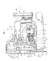
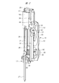
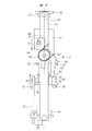
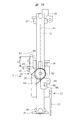
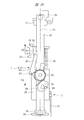
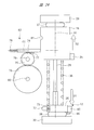
- FIG. 1 is a side cross-sectional view of a driving machine corresponding to some embodiments included in the present invention. It is a perspective view of the striking part provided in the driving machine of FIG. 1, a weight, and a drive mechanism. It is a side view of the striking part provided in the driving machine of FIG. 1, a weight, and a drive mechanism. It is a rear view of the striking part provided in the driving machine of FIG. 1, and a weight. It is a block diagram which shows the control system of the driving machine of FIG. In Embodiment 1 of a driving machine, it is a side view in the state where a striking part is located in a bottom dead center and a weight is located in a top dead center.
- Embodiment 1 of a driving machine it is a side view in the state where a striking part raises from a bottom dead center and a weight falls from a top dead center. It is a side view in the state where a striking part raises further from the position shown in FIG. 7, and a weight falls further from the position shown in FIG.
- FIG. 9 is a side view of a state in which the striking part further rises from the position shown in FIG. 8 and the weight has reached the bottom dead center.
- FIG. 10 is a side view of a state in which the striking part further rises from the position shown in FIG. 9 and the weight is stopped at the bottom dead center.
- FIG. 1 It is a side view of a state where a striking part has reached top dead center and a weight has stopped at the bottom dead center. It is a side view in the state where a striking part descends from a top dead center, and a weight has risen from a bottom dead center. It is a time chart which shows the operation example of the plunger of an impact part, and a weight.
- Embodiment 2 of a driving machine it is a side view in the state where a striking part is located in a bottom dead center and a weight is located in a top dead center.
- a striking part raises from a bottom dead center and it is a side view in the state where a weight falls from a top dead center.
- FIG. 1 It is a side view of a state where a striking part has reached top dead center and a weight has stopped at the bottom dead center. It is a side view in the state where a striking part descends from a top dead center, and a weight has risen from a bottom dead center.
- FIG. 16 is a side view of a state where the striking part further rises from the position shown in FIG. 15 and the weight further descends from the position shown in FIG. 15.
- FIG. 17 is a side view of a state in which the weight is further lowered from the position shown in FIG. 16 and the striking portion has reached top dead center.
- FIG. 18 is a side view of a state in which the weight is further lowered from the position shown in FIG. 17 and the striking portion is stopped at the top dead center. It is a side view of a state where a weight reaches bottom dead center and a strike part has stopped at top dead center. It is a side view in the state where a striking part descends from a top dead center, and a weight has risen from a bottom dead center.
- Embodiment 3 of a driving machine it is a side view in the state where a striking part is located in a bottom dead center and a weight is located in a top dead center.
- FIG. 22 is a side view of a state in which the striking part rises from the bottom dead center shown in FIG. 21 and the weight descends from the top dead center shown in FIG. 21. It is a side view of a state where a strike part starts descent
- An exemplary embodiment of the present invention includes a first movable member operable in a first direction and a second direction, and a second movable member operable in a first direction and a second direction.
- a biasing mechanism biasing the first movable member in the first direction and biasing the second movable member in the second direction; and preventing and allowing the first movable member to operate in the first direction
- a first restriction mechanism, a second restriction mechanism that blocks and allows the second movable member to operate in the second direction, a first state that prevents the second movable member from operating in the second direction, and a second state And a second state that allows the movable member to operate in the second direction. Then, when the first movable member operates in the first direction, the third restricting mechanism is switched from the first state to the second state.
- a driving machine 10 shown in FIG. 1 has a housing 11, a striking portion 12, a magazine 13, an electric motor 14, a conversion mechanism 15, a control board 16, a battery pack 17, and a weight 18.
- the housing 11 has a cylindrical main body 19, a handle 20 connected to the main body 19, and a motor case 21 connected to the main body 19.
- the mounting portion 22 is connected to the handle 20 and the motor case 21.
- the injection unit 23 is provided outside the main body unit 19, and the injection unit 23 is fixed to the main body unit 19.
- the injection unit 23 has an injection passage 24. The user can hold the handle 20 by hand and press the tip of the injection unit 23 against the workpiece W1.
- the magazine 13 is supported by the motor case 21 and the ejection unit 23.
- the motor case 21 is disposed between the handle 20 and the magazine 13 in the direction of the axis A1.
- the magazine 13 accommodates a plurality of fasteners 25.
- the fastener 25 includes a nail, and the material of the fastener 25 includes metal, non-ferrous metal, and steel.
- the fasteners 25 are connected to each other by connection elements.
- the connection element may be either a wire, an adhesive or a resin.
- the fastener 25 is rod-shaped.
- the magazine 13 has a feeder. The feeder sends the stopper 25 accommodated in the magazine 13 to the ejection path 24.
- the striking portion 12 is provided across the inside and the outside of the main body portion 19.
- the striking portion 12 has a plunger 26 disposed in the main body portion 19 and a driver blade 27 fixed to the plunger 26.
- the plunger 26 is made of metal or synthetic resin.
- the plunger 26 has a contact portion 32.
- the chamfered portion 33 is formed on the outer surface of the contact portion 32.
- the chamfered portion 33 is curved.
- the driver blade 27 is made of metal.
- a guide shaft 28 is provided in the main body 19.
- the axis A1 passes through the center of the guide shaft 28.
- the material of the guide shaft 28 may be any of metal, nonferrous metal and steel.
- the top holder 29 and the bottom holder 30 are fixedly provided in the housing 11.
- the material of the top holder 29 and the bottom holder 30 may be any of metal, non-ferrous metal and steel.
- the guide shaft 28 is fixed to the top holder 29 and the bottom holder 30.
- a guide bar 31 is provided in the main body 19. Two guide bars 31 are provided, and the two guide bars 31 are fixed to the top holder 29 and the bottom holder 30.
- the two guide bars 31 are both plate-shaped and arranged in parallel to the axis A1.
- the plunger 26 is attached to the outer peripheral surface of the guide shaft 28, and the plunger 26 is operable along the guide shaft 28 in the direction of the axis A 1.
- the guide shaft 28 radially positions the plunger 26 about the axis A1.
- the guide bar 31 positions the plunger 26 circumferentially around the axis A1.
- the driver blade 27 is operable with the plunger 26 parallel to the axis A1.
- the driver blade 27 is operable in the injection path 24.
- the weight 18 suppresses the reaction that the housing 11 receives.
- the material of the weight 18 may be any of metal, nonferrous metal, steel, and ceramic.
- the weight 18 is attached to the guide shaft 28.
- the weight 18 has a cylindrical shape as an example, and the pin 34 and the weight arm portion 35 are provided on the weight 18.
- the weight 18 is operable along the guide shaft 28 in the direction of the axis A1.
- the guide shaft 28 positions the weight 18 in the radial direction with respect to the axis A1.
- the guide bar 31 positions the weight 18 in the circumferential direction about the axis A1.
- a spring 36 is disposed within the body portion 19 and the spring 36 is disposed between the plunger 26 and the weight 18 in the direction of the axis A1.
- the spring 36 can use a metal compression coil spring as an example.
- the spring 36 can expand and contract in the direction of the axis A1.
- the first end of the spring 36 in the direction of the axis A1 directly or indirectly contacts the plunger 26.
- the second end of the spring 36 in the direction of the axis A1 directly or indirectly contacts the weight 18.
- the spring 36 receives elastic pressure in the direction of the axis A1 and stores elastic energy.
- the spring 36 is an example of a biasing mechanism that biases the striking portion 12 and the weight 18.
- the plunger 26 receives from the spring 36 a biasing force in the first direction D1 approaching the bottom holder 30 in the direction of the axis A1.
- the weight 18 receives a biasing force in the second direction D2 approaching the top holder 29 in the direction along the axis A1, from the spring 36.
- the first direction D1 and the second direction D2 are opposite to each other, and the first direction D1 and the second direction D2 are parallel to the axis A1.
- the plunger 26 and the weight 18 receive biasing force from a physically identical element, a spring 36.
- a weight bumper 37 and a plunger bumper 38 are provided in the main body 19.
- the weight bumper 37 is disposed between the top holder 29 and the weight 18.
- the plunger bumper 38 is disposed between the bottom holder 30 and the plunger 26.
- the weight bumper 37 and the plunger bumper 38 are both made of synthetic rubber.
- the driving machine 10 shown in FIG. 1 shows an example in which the axis A1 is in parallel with the vertical line.
- the actuation of the striking portion 12 or the plunger 26 or the weight 18 in the first direction D1 is referred to as descent.
- actuation of the striking portion 12 or the plunger 26 or the weight 18 in the second direction D2 is referred to as lifting.
- the striking portion 12 and the weight 18 can be reciprocated in the direction of the axis A1.
- the battery pack 17 shown in FIG. 1 is attachable to and detachable from the mounting portion 22.
- the battery pack 17 has a housing case 39 and a plurality of battery cells housed in the housing case 39.
- the battery cell is a secondary battery capable of charging and discharging, and the battery cell may be any of a lithium ion battery, a nickel hydrogen battery, a lithium ion polymer battery, and a nickel cadmium battery.
- the battery pack 17 is a DC power supply, and the electric power of the battery pack 17 can be supplied to the electric motor 14.
- the control board 16 shown in FIG. 1 is provided in the mounting portion 22, and the controller 40 and the inverter circuit 41 shown in FIG. 5 are provided on the control board 16.
- the controller 40 is a microcomputer having an input port, an output port, an arithmetic processing unit, and a storage unit.
- the inverter circuit 41 has a plurality of switching elements, and the plurality of switching elements can be turned on and off, respectively.
- the controller 40 outputs a signal for controlling the inverter circuit 41.
- An electric circuit is formed between the battery pack 17 and the electric motor 14.
- the inverter circuit 41 is a part of the electrical circuit, and connects and disconnects the electrical circuit.
- the trigger 42 and the trigger switch 43 are provided on the handle 20, and when the user applies an operating force to the trigger 42, the trigger switch 43 is turned on. When the user releases the operating force applied to the trigger 42, the trigger switch 43 is turned off.
- a position detection sensor 44 shown in FIG. 5 is provided in the housing 11. The position detection sensor 44 estimates the positions of the plunger 26 and the weight 18 in the direction of the axis A1, for example, based on the rotation angle of the electric motor 14, and outputs a signal.
- the controller 40 receives the signal of the trigger switch 43 and the signal of the position detection sensor 44, and outputs a signal for controlling the inverter circuit 41.
- the electric motor 14 has a rotor 84 and a stator 45, and a motor shaft 46 is attached to the rotor 84.
- the electric motor 14 rotates the motor shaft 46 when power is supplied from the battery pack 17.
- a reduction gear 47 is disposed in the motor case 21.
- the reduction gear 47 has a plurality of sets of planetary gear mechanisms, an input element 48 and an output element 49.
- the input element 48 is connected to the motor shaft 46.
- the electric motor 14 and the reduction gear 47 are disposed concentrically about the axis B1.
- the driving machine 10 shown in FIG. 1 shows an example in which the angle between the axis A1 and the axis B1 is 90 degrees.
- the conversion mechanism 15 converts the rotational force of the output element into the actuating force of the striking portion 12 and the actuating force of the weight 18.
- the conversion mechanism 15 has a first gear 50, a second gear 51 and a third gear 52.
- the material of the first gear 50, the second gear 51, and the third gear 52 may be any of metal, nonferrous metal, and steel.
- a holder 53 is provided in the housing 11, and the output element 49 is rotatably supported by the holder 53.
- the first gear 50 is fixed to the output element 49.
- the second gear 51 is rotatably supported by the support shaft 54.
- the third gear 52 is rotatably supported by the support shaft 55.
- the support shafts 54 and 55 are attached to the holder 53.
- the first gear 50 is rotatable about the axis B1
- the second gear 51 is rotatable about the axis B2
- the third gear 52 is rotatable about the axis B3.
- the axes B1, B2 and B3 are arranged at intervals in the direction of the axis A1.
- the axis B2 is disposed between the axis B1 and the axis B3.
- the axes B1, B2, B3 are parallel to one another.
- the third gear 52 is disposed between the second gear 51 and the top holder 29 in the direction of the axis A1.
- the first gear 50 is disposed between the second gear 51 and the magazine 13 in the direction of the axis A1.
- the outer diameter of the first gear 50, the outer diameter of the second gear 51, and the outer diameter of the third gear 52 are the same.
- the second gear 51 meshes with the first gear 50 and the third gear 52.
- the cam roller 57 is provided on the first gear 50, the two cam rollers 58 are provided on the second gear 51, and the two cam rollers 59 are provided on the third gear 52. .
- the cam roller 57 can rotate on the first gear 50.
- the two cam rollers 58 are disposed on the same circumference around the axis B2.
- the two cam rollers 58 can rotate independently with respect to the second gear 51.
- the two cam rollers 59 can rotate on the third gear 52 respectively.
- the two cam rollers 59 are disposed on the same circumference around the axis B3.
- the material of the cam rollers 57, 58, 59 may be any of metal, non-ferrous metal and steel.
- the first arm 85 and the second arm 60 are provided on the plunger 26.
- the first arm 85 and the second arm 60 are made of metal.
- the cam roller 57 can engage and release the first arm portion 85.
- the cam roller 58 can engage and release the second arm portion 60.
- the cam roller 59 can be engaged with and released from the weight arm portion 35.
- the latch 61 is attached to the guide bar 31.
- the latch 61 is rotatable relative to the guide bar 31 about the support shaft 62.
- the support shaft 62 is, as an example, located within the arrangement range of the third gear 52 in the direction of the axis A1.
- a metal spring 63 is attached to the latch 61.
- the spring 63 is, for example, a torsion coil spring, and the first end in the winding direction of the spring 63 is engaged with the latch 61, and the second end in the winding direction of the spring 63 is engaged with the guide bar 31 .
- the spring 63 biases the latch 61 clockwise around the support shaft 62.
- a stopper 64 is provided on the latch 61, and when the stopper 64 contacts the guide bar 31, the latch 61 is stopped.
- the latch 61 has an arm 65 and a hook 66. The arm 65 and the hook 66 are disposed apart from the support shaft 62 in the longitudinal direction of the latch 61.
- the hook 66 is located between the top holder 29 and the support shaft 62 in the direction of the axis A1.
- the arm 65 is located between the bottom holder 30 and the support shaft 62 in the direction of the axis A1.
- the hook 66 is capable of contacting and disengaging the pin 34. Specifically, the hooks 66 can engage and release the pins 34.
- the arm 65 can contact and move away from the contact portion 32.
- a chamfer 67 is formed on the outer surface of the arm 65.
- the chamfered portion 67 is curved.
- the latch 61 and the spring 63 constitute a third restricting mechanism 71.
- the controller 40 detects that the trigger switch 43 is off, the controller 40 does not supply power to the electric motor 14 and stops the motor shaft 46.
- the electric motor 14 is stopped, as shown in FIG. 6, the plunger 26 is stopped at a position where it contacts the plunger bumper 38, that is, at the bottom dead center.
- the weight 18 is biased by the elastic force of the spring 36, and stops at the position where it contacts the weight bumper 37, that is, at the top dead center.
- the controller 40 processes the signal of the position detection sensor 44 to estimate the position of the plunger 26 and the weight 18 in the direction of the axis A1.
- the cam rollers 57, 58 are separated from the second arm portion 60.
- the cam roller 59 is separated from the weight arm portion 35.
- the controller 40 When the user presses the tip of the injection unit 23 against the workpiece W1 and the controller 40 detects that the trigger switch 43 is turned on, the controller 40 supplies power to the electric motor 14 to rotate the motor shaft 46 forward.
- the rotational force of the motor shaft 46 is amplified by the reduction gear 47 and transmitted to the first gear 50, and the first gear 50 rotates counterclockwise in FIG.
- cam roller 57 When the cam roller 57 is engaged with the first arm 85 while the first gear 50 and the second gear 51 are rotating, one cam roller 58 is engaged with the second arm 60. Thereafter, the cam roller 57 is released from the first arm portion 85. Further, when one cam roller 58 is engaged with the second arm portion 60, another cam roller 58 is engaged with the second arm portion 60. Then, the cam roller 58 previously engaged with the second arm 60 is released from the second arm 60.
- the weight 18 reaches the bottom dead center and the plunger 26 is further raised. Also, the contact portion 32 is maintained in contact with the arm 65. Further, the third gear 52 is rotated, and the two cam rollers 59 are both released from the weight arm portion 35. However, since the contact portion 32 is in contact with the arm 65, the latch 61 is at rest. That is, as shown in FIG. 11, the hook 66 is engaged with the pin 34, and the weight 18 is at rest.
- the plunger 26 When the plunger 26 is lowered, that is, when the striking portion 12 is lowered, the driver blade 27 strikes the stopper 25 located in the injection path 24. The stopper 25 is driven into the workpiece W1. After the driver blade 27 strikes the stopper 25, the plunger 26 collides with the plunger bumper 38 as shown in FIG. The plunger bumper 38 absorbs part of the kinetic energy of the striking part 12. Also, the weight 18 collides with the weight bumper 37. The weight bumper 37 absorbs part of the kinetic energy of the weight.
- the weight 18 when the striking part 12 operates in the first direction to strike the stopper 25, the weight 18 operates in the second direction opposite to the first direction. For this reason, it is possible to reduce reaction when the striking portion 12 strikes the stopper 25. Therefore, the relationship between the first timing when the plunger 26 starts actuation from top dead center to bottom dead center and the second timing when the weight 18 starts actuation from bottom dead center to top dead center is stabilized. And, it becomes easy to reduce reaction.
- the controller 40 estimates the position of the plunger 26 in the direction of the axis A1, and stops the electric motor 14 before the plunger 26 starts to descend until it collides with the plunger bumper 38. Therefore, the plunger 26 stops at the bottom dead center in contact with the plunger bumper 38, and the weight 18 stops at the top dead center in contact with the weight bumper 37. Then, when the user releases the operating force to the trigger 42 and applies the operating force to the trigger 42 again, the controller 40 rotates the electric motor 14, and the striking unit 12 and the weight 18 operate in the same manner as described above.
- FIG. 13 is a time chart showing an operation example of the plunger 26 and the weight 18.
- the position of the plunger 26 is indicated by a solid line
- the position of the weight 18 is indicated by a broken line.
- the plunger 26 stops at the bottom dead center before time t1
- the weight 18 stops at the top dead center before time t1.
- the plunger 26 starts its operation from the bottom dead center to the top dead center at time t1.
- the weight 18 is also stopped at the top dead center after time t1.
- the weight 18 starts operating from top dead center to bottom dead center at time t2.
- the weight 18 reaches the bottom dead center at time t3, and the weight 18 stops at the bottom dead center after time t3.
- the hook 66 engages with the pin 34 at time t4, and the latch 61 is in a state capable of holding the weight 18.
- the plunger 26 reaches the top dead center at time t5, and the plunger 26 stops at the top dead center after time t5.
- the plunger 26 starts to descend from the top dead center to the bottom dead center at time t6. Since the latch 61 holds the weight 18 at time t6, the weight 18 is also stopped at the bottom dead center after time t6.
- the weight 18 starts operating from the bottom dead center toward the top dead center. Then, the plunger 26 reaches the bottom dead center at time t8, and the weight 18 reaches the top dead center at time t8. The plunger 26 may reach the bottom dead center at time t8, and the weight 18 may reach the top dead center after time t8.
- the latch 61 operates according to the position in the direction of the axis A1 of the plunger 26 which is an element of the striking portion 12, and the plunger 26 operates from top dead center to bottom dead center. The relationship between the first timing to start and the second timing to start the operation from the bottom dead center to the top dead center is determined.
- the conditions of the driving machine 10 include at least one of the following: variations in the shape or size of the elements constituting the conversion mechanism 15; and variations in the assembly state of the elements constituting the conversion mechanism 15.
- the first embodiment of the driving machine 10 adopts either the configuration for increasing the stroke amount of the weight 18 or the configuration for increasing the mass of the weight 18. I did not. Therefore, at least one of the increase in size and the increase in weight of the driving machine 10 can be avoided.
- the first embodiment of the driving machine 10 can change or adjust the timing at which the plunger 26 rises from the bottom dead center by setting the number of cam rollers 57 and the position of the cam roller 57 in the rotation direction of the first gear 50. .
- the embodiment 1 of the driving machine 10 can change or adjust the timing at which the plunger 26 reaches the top dead center.
- the first embodiment of the driving machine 10 can change or adjust the timing at which the plunger 26 descends from the top dead center by setting the number of cam rollers 58 and the position of the cam roller 58 in the rotation direction of the second gear 51. .
- the first embodiment of the driving machine 10 can change or adjust the timing at which the weight 18 descends from the top dead center by setting the number of cam rollers 59 and the position of the cam roller 59 in the rotational direction of the third gear 52. is there.
- the embodiment 1 of the driving machine 10 can change or adjust the timing at which the weight 18 reaches the bottom dead center.
- the timing at which the weight 18 rises from the bottom dead center can be defined as the required time from the timing at which the plunger 26 descends from the top dead center to the timing at which the weight 18 rises from the bottom dead center.
- the required time corresponds to the time from time t6 to time t7 in the time chart of FIG.
- the length L1 of the arm 65 is a value at which the contact portion 32 blocks the operation of the latch 61 when the arm 65 and the contact portion 32 are in contact with each other. For example, as the length L1 of the arm 65 is set relatively short, the required time becomes relatively short.
- a second embodiment of a driving machine having a third restricting mechanism will be described with reference to FIG.
- a pin 68 is provided on the plunger 26.
- the pin 34 shown in FIG. 6 is not provided to the weight 18 of FIG.
- the contact portion 69 is provided on the weight 18, and the chamfered portion 70 is formed on the outer surface of the contact portion 69.
- the chamfer 70 is curved.
- the contact portion 32 shown in FIG. 6 is not provided on the plunger 26 of FIG.
- the support shaft 62 supporting the latch 61 is disposed at a position closer to the bottom holder 30 than the middle between the top holder 29 and the bottom holder 30 in the direction of the axis A1.
- the arm 65 of the latch 61 is located between the top holder 29 and the support shaft 62 in the direction of the axis A1.
- the hook 66 of the latch 61 is located between the bottom holder 30 and the support shaft 62 in the direction of the axis A1.
- the latch 61 is biased clockwise about the support shaft 62 in FIG.
- the plunger 26, the weight 18 and the latch 61 shown in FIG. 14 can be provided in the driving machine 10 shown in FIG. 1, and the driving machine 10 is the second embodiment.
- the cam roller 57 of the first gear 50 shown in FIG. 4 can be engaged with and released from the first arm portion 85, and the cam roller 58 of the second gear 51 can be used as the second arm portion 60. It can be engaged and released.
- the cam roller 59 of the third gear 52 can be engaged with and released from the weight arm portion 35.
- Embodiment 2 of the driving machine 10 The usage example of Embodiment 2 of the driving machine 10 is demonstrated.
- the electric motor 14 shown in FIG. 1 When the electric motor 14 shown in FIG. 1 is stopped, it stops at the bottom dead center as shown in FIG. 14, and the weight 18 stops at the top dead center. Further, the stopper 64 is in contact with the guide bar 31 and the latch 61 is stopped. Also, the arm 65 is separated from the contact portion 69, and the hook 66 is released from the pin 68.
- the weight 18 When the electric motor 14 shown in FIG. 1 is rotated, the weight 18 operates in the second direction D3 against the biasing force of the spring 36 as shown in FIG. That is, the weight 18 descends. Further, similarly to the first embodiment of the driving machine 10, the plunger 26 shown in FIG. 15 operates in the first direction D4. That is, the plunger 26 ascends.
- the first direction D4 and the second direction D3 are parallel to the axis A1.
- the plunger 26 reaches top dead center and the weight 18 further descends. Also, the contact portion 69 is maintained in contact with the arm 65. Further, the cam roller 58 shown in FIG. 4 is released from the second arm portion 60 shown in FIG. Then, the rotational force of the electric motor 14 shown in FIG. 1 is not transmitted to the plunger 26 shown in FIG. However, the contact portion 69 contacts the arm 65, and the contact portion 69 stops the latch 61. That is, as shown in FIG. 19, the hook 66 remains engaged with the pin 68, and the plunger 26 is at rest.
- the latch 61 operates clockwise by the biasing force of the spring 63. Then, the hook 66 is released from the pin 68, and the plunger 26 is lowered from the top dead center by the biasing force of the spring 36.
- the driver blade 27 strikes the stopper 25 located in the injection path 24. After the driver blade 27 strikes the stopper 25, the plunger 26 collides with the plunger bumper 38 as shown in FIG. Also, the weight 18 collides with the weight bumper 37. Also in the second embodiment of the driving machine 10, it is possible to reduce the reaction when the striking portion 12 strikes the stopper 25.
- the position of the plunger 26 in the second embodiment of the driving machine 10 is indicated by a broken line, and the position of the weight 18 is indicated by a solid line.
- the position of the plunger 26 in the second embodiment of the driving machine 10 corresponds to the position of the weight 18 in the first embodiment of the driving machine 10, and the position of the weight 18 in the second embodiment is the position of the plunger 26 in the first embodiment.
- Embodiment 2 of the driving machine 10 can acquire the same effect as Embodiment 1 of the driving machine 10.
- the second embodiment of the driving machine 10 can change or adjust the timing at which the weight 18 descends from the top dead center by setting the number of cam rollers 59 and the position of the cam roller 59 in the rotation direction of the third gear 52. .
- the embodiment 2 of the driving machine 10 can change or adjust the timing at which the weight 18 reaches the bottom dead center by setting the diameter of the circumscribed circle of the cam roller 59 in the radial direction of the third gear 52.
- the second embodiment of the driving machine 10 can change or adjust the timing at which the plunger 26 ascends from the bottom dead center by setting the number of cam rollers 57 and the position of the cam roller 57 in the rotation direction of the first gear 50. .
- the embodiment 2 of the driving machine 10 can change or adjust the timing at which the plunger 26 reaches the top dead center by setting the diameter of the circumscribed circle of the cam roller 57 in the radial direction of the first gear 50.
- Embodiment 2 of the driving machine 10 can change or adjust the timing at which the plunger 26 descends from the top dead center by setting the length L2 in the direction of the axis A1 of the arm 65 as shown in FIG. is there.
- the timing at which the plunger 26 descends from the top dead center can be defined as the required time from the timing at which the weight 18 rises from the bottom dead center to the timing at which the plunger 26 descends from the top dead center.
- the required time corresponds to the time from time t6 to time t7 in the time chart of FIG.
- the length L2 of the arm 65 is a value that can prevent the contact portion 69 from operating the latch 61 when the arm 65 and the contact portion 69 are in contact with each other. For example, as the length L2 of the arm 65 is set relatively short, the required time becomes relatively short.
- FIG. A pressing member 72 is attached to the plunger 26.
- the pressing member 72 is a metal pin as an example.
- a spring 73 is attached to the plunger 26.
- the spring 73 is a metal compression spring as an example, and the spring 73 biases the pressing member 72 in a direction intersecting the axis A1.
- the pressing member 72 is biased by the spring 73, contacts the stopper, and stops at a position.
- the tip end portion of the pressing member 72 has a sufficient coefficient of friction to convert the actuating force of the pressing member 72 into a driving force of the gear 76, that is, a rotational force, when in contact with the gear 76.
- the configuration for setting the coefficient of friction of the tip of the pressing member 72 in this manner includes selection of the material of at least a part of the pressing member 72 and selection of the shape of the tip of the pressing member 72.
- One example of the selection of the material of at least a part of the pressing member 72 is to make at least a part of the pressing member 72 made of synthetic rubber.
- One example of the selection of the shape of the tip of the pressing member 72 includes a convex portion provided on the tip of the pressing member 72 and a rack-like uneven portion.
- the movable member 74 and the gears 75 and 76 are provided in the housing 11 shown in FIG.
- the movable member 74 is operable in the direction of an axis C1 intersecting with the axis A1.
- the movable member 74 is a metal pin as an example.
- a guide member which supports the movable member 74 in the direction of the axis C1 is provided in the housing 11.
- the movable member 74 has a rack 77 disposed along the direction of the axis C1.
- the outer diameter of the gear 76 is larger than the outer diameter of the gear 75, and the gear 75 and the gear 76 mesh with each other.
- the gear 76 has no teeth on a part of the outer peripheral surface that transmits the driving force by the frictional force when contacting the pressing member 72. Moreover, it is also possible to provide a tooth engaged with the convex portion and the concave and convex portion of the pressing member 72 in a portion of the gear 76 in contact with the tip end portion of the pressing member 72.
- the gear 75 meshes with the rack 77.
- the gear 75 is rotatable about the support shaft 79, and the gear 76 is rotatable about the support shaft 80.
- a spring 78 is provided in the housing 11 and biases the movable member 74 towards the weight 18 in the direction of the axis C1.
- the spring 78 is a metal compression spring as an example.
- the weight 18 is provided with an engaging portion 81.
- the engaging portion 81 is, for example, a recess provided on the outer surface of the weight 18.
- the tip of the movable member 74 is engageable with and disengageable from the engagement portion 81.
- the movable member 74, the gears 75 and 76, and the spring 78 constitute a third restriction mechanism 82.
- the third restriction mechanism 82, the weight 18 and the plunger 26 shown in FIG. 21 can be provided in the driving machine 10 shown in FIG. 1, and the driving machine 10 is the third embodiment.
- the plunger 26 shown in FIG. 21 has a second arm 60.
- the cam roller 57 shown in FIG. 4 is engageable with and releasable from the first arm 85 shown in FIG. 21, and the cam roller 58 is engageable with and releasable from the second arm 60.
- the weight 18 shown in FIG. 21 has a weight arm portion 35.
- the cam roller 59 shown in FIG. 4 can be engaged with and released from the weight arm portion 35 shown in FIG.
- Embodiment 3 of the driving machine 10 is demonstrated.
- the plunger 26 is biased by the spring 36 and stopped at the bottom dead center as shown in FIG.
- the pressing member 72 is separated from the gear 76.
- the weight 18 is biased by the spring 36 and stops at the top dead center. Since the gears 75 and 76 are stopped, the movable member 74 is stopped at a predetermined position in the direction of the axis C1. The movable member 74 is released from the engaging portion 81.
- the downward force of the plunger 26 causes the gear 76 to rotate clockwise by a predetermined angle in FIG.
- the gear 75 rotates counterclockwise in FIG. 23 by a predetermined angle. Therefore, the movable member 74 separates from the weight 18 against the force of the spring 78.
- the pressing member 72 separates from the gear 76, the gears 76 and 75 stop, and the movable member 74 stops at a predetermined position.
- the gears 75 and 76 and the movable member 74 operate according to the position of the plunger 26 in the direction of the axis A1, and the first timing at which the plunger 26 starts to descend from top dead center; The relationship with the second timing at which the weight 18 starts to rise from the bottom dead center is determined. Therefore, the third embodiment of the driving machine 10 can obtain the same effect as the first embodiment of the driving machine 10.
- the third embodiment of the driving machine 10 can change or adjust the timing at which the plunger 26 ascends from the bottom dead center on the same principle as the first embodiment of the driving machine 10.
- the third embodiment of the driving machine 10 can change or adjust the timing at which the plunger 26 reaches the top dead center by the same principle as the first embodiment of the driving machine 10.
- the third embodiment of the driving machine 10 can change or adjust the timing at which the plunger 26 descends from the top dead center on the same principle as the first embodiment of the driving machine 10.
- the third embodiment of the driving machine 10 can change or adjust the timing at which the weight 18 descends from the top dead center on the same principle as the first embodiment of the driving machine 10.
- the third embodiment of the driving machine 10 can change or adjust the timing at which the weight 18 reaches the bottom dead center by the same principle as the first embodiment of the driving machine 10.
- the rotation angle of the gear 76 with respect to the amount of operation of the plunger 26, the transmission ratio when transmitting power from the gear 76 to the gear 75, and the movable member 74 with respect to the rotation angle of the gear 75 can be changed or adjusted based on the amount of operation when the weight 18 moves away from the weight 18.
- the timing at which the weight 18 rises from the bottom dead center can be defined as the required time from the timing at which the plunger 26 descends from the top dead center to the timing at which the weight 18 rises from the bottom dead center.
- the function of the movable member 74 to hold the weight 18 at the bottom dead center becomes easy to be released from the engaging portion 81 as the amount of operation when the movable member 74 moves away from the weight 18 is relatively large. Is more likely to be released.
- the required time becomes shorter as the rotation angle of the gear 76 relative to the amount of actuation of the plunger 26 is relatively larger.
- the required time is shorter as the operation amount of the movable member 74 relative to the change amount of the rotation angle of the gear 75 is relatively larger.
- the required time is shorter as the gear ratio between the gear 76 and the gear 75 is relatively smaller.
- the driving machine 10 is an example of a driving machine.
- the first direction D1 is an example of a first direction
- the second direction D2 is an example of a second direction.
- the striking part 12 is an example of a first movable member
- the weight 18 is an example of a second movable member.
- the spring 36 is an example of a biasing mechanism.
- the second gear 51 and the cam roller 58 are an example of a first restricting mechanism
- the third gear 52 and the cam roller 59 are an example of a second restricting mechanism.
- the drive mechanism 83 is an example of a drive mechanism.
- the third control mechanism 71 is an example of a third control mechanism.
- the support shaft 62 is an example of a support shaft
- the latch 61 is an example of a latch.
- the arm 65 is an example of a first end
- the guide bar 31 and the guide shaft 28 are an example of a support member.
- the hook 66 is an example of the second end. A state in which the arm 65 contacts the contact portion 32 and the hook 66 is engaged with the pin 34 as shown in FIG. 11 is an example of the first state. A state in which the arm 65 is separated from the contact portion 32 and the hook 66 is released from the pin 34 as shown in FIG. 12 is an example of the second state.
- Weight 18 is an example of the 1st movable member.
- the striking part 12 is an example of a second movable member and a striking part.
- the first direction D4 is an example of a first direction
- the second direction D3 is an example of a second direction.
- the second gear 51 and the cam roller 58 are an example of a first restricting mechanism
- the first gear 50 and the cam roller 57 are an example of a second restricting mechanism.
- the state in which the arm 65 contacts the contact portion 69 and the hook 66 is engaged with the pin 68 as shown in FIG. 19 is an example of the first state.
- the state in which the arm 65 is separated from the contact portion 69 and the hook 66 is released from the pin 68 is an example of the second state.
- the other technical meanings in the second embodiment are the same as the technical meanings in the first embodiment.
- the plunger 26 which has the press member 72 is an example of a 1st movable member.
- the third restricting mechanism 82 is an example of a third restricting mechanism, and the gears 75 and 76 are an example of a rotating element.
- the movable member 74 is an example of a restriction shaft, and the spring 78 is an example of an elastic member.
- the state in which the pressing member 72 is in contact with the gear 76 and the movable member 74 is engaged with the engaging portion 81 is an example of the first state of the third restriction mechanism. As shown in FIG.
- the state in which the pressing member 72 is separated from the gear 76 and the movable member 74 is separated from the weight 18 is an example of the second state of the third restriction mechanism.
- the other technical meanings in the third embodiment are the same as the technical meanings in the first embodiment.
- the driving machine is not limited to the above-described embodiment, and various modifications can be made without departing from the scope of the invention.
- the controller 40 stops the striking unit 12 at the bottom dead center and the weight 18 at the top dead center.
- the example which controls the stop position of the electric motor 14 so that it might stop was demonstrated.
- the striking unit 12 stops between the bottom dead center and the top dead center, and the weight 18 stops between the top dead center and the bottom dead center. It is also possible to control the stop position of the electric motor 14 as follows.
- the use state of the driving machine 10 may be either a first use state in which the axis A1 is parallel to the vertical line or a second use state in which the axis A1 intersects the vertical line.
- the second use state may be either a state in which the intersection angle between the axis A1 and the vertical line is 90 degrees, and a state in which the intersection angle between the axis A1 and the vertical line is different from 90 degrees.
- the use state of the driving machine 10 is a third use state in which the striking part 12 is positioned below the weight 18 in the direction of the axis A1, and the fourth example in which the striking part 12 is positioned above the weight 18 in the direction of the axis A1. Any of the use condition and the fifth use condition in which the striking part 12 is positioned at the same height as the weight 18 in the direction of the axis A1 may be used.
- actuation of the striking portion 12 or the weight 18 in the first direction D1 can be defined as “advance”.
- actuation of the striking portion 12 or the weight 18 in the second direction D2 can be defined as "retraction”.
- actuation of the striking portion 12 or the weight 18 in the second direction D3 can be defined as “advance”.
- actuation of the striking portion 12 or the weight 18 in the first direction D4 can be defined as "retraction”.
- actuation of the striking portion 12 or the weight 18 in the first direction D1 can be defined as "raising”. Moreover, it can be defined as “falling” that the striking part 12 or the weight 18 operate
- operation of the striking part 12 or the weight 18 in the second direction D3 can be defined as "raising”.
- actuation of the striking portion 12 or the weight 18 in the first direction D4 can be defined as “descent”.
- the biasing mechanism which biases the first movable member in the first direction and biases the second movable member in the second direction is a spring made of nonferrous metal other than a metal spring, synthetic rubber, gas spring , Including magnetic springs.
- the metal spring or the nonferrous metal spring may be either a compression spring or a tension spring.
- the metal and the non-ferrous metal may be a composite or combined spring.
- the biasing mechanism that biases the first movable member in the first direction and the biasing mechanism that biases the second movable member in the second direction are physically the same member, or physically Include those that are separate members.
- the biasing mechanism actuates the first movable member at a speed capable of striking the stopper and operates the second movable member in the direction opposite to the first movable member. It may be a mechanism.
- the first restriction mechanism directly or indirectly contacts the first movable member to prevent the first movable member from operating in the first direction.
- the principle that the first restriction mechanism blocks the operation of the first movable member may be either an engagement force or a frictional force. Blocking the operation of the first movable member by the first restricting mechanism includes stopping the first movable member and restricting the operation of the first movable member.
- the second restricting mechanism directly or indirectly contacts the second movable member to prevent the second movable member from operating in the second direction.
- the principle by which the second restriction mechanism blocks the operation of the second movable member may be either an engagement force or a frictional force. Blocking the operation of the second movable member by the second restricting mechanism includes stopping the second movable member and restricting the operation of the second movable member. To allow the first movable member or the second movable member to operate means that the first movable member or the second movable member can be operated by the biasing force of the biasing mechanism.
- the respective actuations of the first movable member, the second movable member, the regulating shaft, the rotary element and the latch can also be defined as the respective movements of the first movable member, the second movable member, the regulating shaft, the rotary element and the latch It is.
- the third restricting mechanism acts on the first movable member and the third movable member directly or indirectly to interlock the operation of the first drive member and the second drive member, at least one embodiment. It is not limited to the means for deregulation described in. For example, not only the configuration in which the state of the third restricting mechanism is switched by the operation of the first movable member exemplified in the above embodiment, but also the first restricting mechanism and the third restricting mechanism are engaged directly or indirectly
- the invention also includes a configuration in which the first restriction mechanism permits the operation of the first movable member, and the first restriction mechanism switches the state of the third restriction mechanism.
- the drive mechanism includes a motor as a motive power source, and a power transmission mechanism that transmits the rotational force of the motor.
- the power transmission mechanism includes pulleys, gears, rollers, sprockets, belts, and chains. Also, at least a part of the power transmission mechanism and at least a part of the first actuation mechanism may be common. Furthermore, at least a part of the power transmission mechanism and at least a part of the second actuation mechanism may be common.
- the motor includes an electric motor, a hydraulic motor, a pneumatic motor, and an engine. The power supply of the electric motor may be either a DC power supply or an AC power supply.
- the striking portion may use a piston and a driver blade instead of the plunger and the driver blade.
- the rotating element of the third restriction mechanism includes a gear and a roller.
- the elastic member of the third restriction mechanism may be any of a metal spring, a nonmetal spring, and a synthetic rubber.
- the metal spring or the nonmetal spring may be either a compression spring or a tension spring.
- the third restricting mechanism shown in Embodiment 1 and Embodiment 2 can be provided in at least one of the two guide bars 31.
Landscapes
- Engineering & Computer Science (AREA)
- Mechanical Engineering (AREA)
- Portable Nailing Machines And Staplers (AREA)
Abstract
L'objectif de la présente invention est de fournir une machine d'entraînement permettant de stabiliser la relation entre la synchronisation d'un premier élément mobile destiné à démarrer une opération dans une première direction et la synchronisation d'un deuxième élément mobile destiné à démarrer une opération dans une deuxième direction. La machine d'entraînement, qui possède un premier élément mobile (12), qui peut fonctionner dans une première direction (D1) et dans une deuxième direction (D2), et un deuxième élément mobile (18), qui peut fonctionner dans la première direction (D1) et dans la deuxième direction (D2), comprend : un mécanisme de sollicitation (36), qui sollicite le premier élément mobile (12) et le deuxième élément mobile (18) ; un premier mécanisme de restriction ; un deuxième mécanisme de restriction ; et un troisième mécanisme de restriction (71), le premier élément mobile (12) étant empêché de fonctionner dans la première direction (D1), le troisième mécanisme de restriction (71) étant maintenu dans un premier état, et lorsque le premier élément mobile (12) est autorisé à fonctionner dans la première direction (D1) et fonctionne, le troisième mécanisme de restriction (71) étant commuté du premier état à un deuxième état.
Priority Applications (4)
| Application Number | Priority Date | Filing Date | Title |
|---|---|---|---|
| US16/756,098 US11491625B2 (en) | 2017-10-31 | 2018-09-28 | Driving machine |
| EP18872102.1A EP3705234B1 (fr) | 2017-10-31 | 2018-09-28 | Machine d'entraînement |
| CN201880071536.9A CN111315537B (zh) | 2017-10-31 | 2018-09-28 | 打入机 |
| JP2019550896A JP6897789B2 (ja) | 2017-10-31 | 2018-09-28 | 打込機 |
Applications Claiming Priority (2)
| Application Number | Priority Date | Filing Date | Title |
|---|---|---|---|
| JP2017-210793 | 2017-10-31 | ||
| JP2017210793 | 2017-10-31 |
Publications (1)
| Publication Number | Publication Date |
|---|---|
| WO2019087637A1 true WO2019087637A1 (fr) | 2019-05-09 |
Family
ID=66331822
Family Applications (1)
| Application Number | Title | Priority Date | Filing Date |
|---|---|---|---|
| PCT/JP2018/036307 Ceased WO2019087637A1 (fr) | 2017-10-31 | 2018-09-28 | Machine d'entraînement |
Country Status (6)
| Country | Link |
|---|---|
| US (1) | US11491625B2 (fr) |
| EP (1) | EP3705234B1 (fr) |
| JP (1) | JP6897789B2 (fr) |
| CN (1) | CN111315537B (fr) |
| TW (1) | TWI778163B (fr) |
| WO (1) | WO2019087637A1 (fr) |
Cited By (1)
| Publication number | Priority date | Publication date | Assignee | Title |
|---|---|---|---|---|
| JP2023006687A (ja) * | 2021-06-30 | 2023-01-18 | 工機ホールディングス株式会社 | 作業機 |
Families Citing this family (5)
| Publication number | Priority date | Publication date | Assignee | Title |
|---|---|---|---|---|
| JP6627990B2 (ja) * | 2016-11-30 | 2020-01-08 | 工機ホールディングス株式会社 | 打込機 |
| US11491625B2 (en) * | 2017-10-31 | 2022-11-08 | Koki Holdings Co., Ltd. | Driving machine |
| AT523156B1 (de) * | 2019-12-18 | 2021-06-15 | Rohrmoser Florian | Elektrisch-mechanisch betriebenes Werkzeug zum Eintreiben von Befestigungsmitteln |
| TWI824800B (zh) * | 2022-10-31 | 2023-12-01 | 力肯實業股份有限公司 | 電動打釘機之內轉子式擊釘驅動裝置 |
| TWI869998B (zh) * | 2023-08-29 | 2025-01-11 | 匯寬實業有限公司 | 電動釘槍及其操作方法 |
Citations (5)
| Publication number | Priority date | Publication date | Assignee | Title |
|---|---|---|---|---|
| JP2008260124A (ja) * | 2007-04-13 | 2008-10-30 | Hilti Ag | 打込み装置 |
| US20090078734A1 (en) * | 2007-09-20 | 2009-03-26 | Chin-Hsiun Chang | Counterforce-counteracting device for a nailer |
| JP2012183632A (ja) * | 2011-02-18 | 2012-09-27 | Max Co Ltd | 打ち込み工具 |
| WO2015015967A1 (fr) * | 2013-07-31 | 2015-02-05 | 日立工機株式会社 | Machine d'enfoncement |
| WO2016031716A1 (fr) | 2014-08-28 | 2016-03-03 | 日立工機株式会社 | Machine de redistribution |
Family Cites Families (40)
| Publication number | Priority date | Publication date | Assignee | Title |
|---|---|---|---|---|
| US2575455A (en) * | 1945-12-12 | 1951-11-20 | Bocjl Corp | Impact tool |
| US3243093A (en) * | 1964-02-04 | 1966-03-29 | United Shoe Machinery Corp | Spring actuated nailers |
| US3589588A (en) * | 1969-07-14 | 1971-06-29 | George O Vasku | Impact tool |
| CA1166401A (fr) * | 1981-12-11 | 1984-05-01 | James D. Cunningham | Outil electromecanique de percussion, et mode d'emploi connexe |
| US5004140A (en) * | 1989-04-24 | 1991-04-02 | Makita Electric Works, Ltd. | Electrically-operated tacker |
| US5802691A (en) * | 1994-01-11 | 1998-09-08 | Zoltaszek; Zenon | Rotary driven linear actuator |
| JP3676879B2 (ja) * | 1995-07-25 | 2005-07-27 | 株式会社マキタ | 締結具打込み工具 |
| US6604666B1 (en) * | 2001-08-20 | 2003-08-12 | Tricord Solutions, Inc. | Portable electrical motor driven nail gun |
| US6705503B1 (en) * | 2001-08-20 | 2004-03-16 | Tricord Solutions, Inc. | Electrical motor driven nail gun |
| US20040232194A1 (en) * | 2002-03-07 | 2004-11-25 | Pedicini Christopher S. | Enhanced electrical motor driven nail gun |
| US6761299B2 (en) * | 2002-09-18 | 2004-07-13 | Illinois Tool Works Inc. | Magazine clutch assembly |
| ATE467487T1 (de) * | 2003-03-21 | 2010-05-15 | Black & Decker Inc | Schwingungsreduziervorrichtung für kraftbetriebenes werkzeug und solch eine vorrichtung enthaltendes kraftbetriebenes werkzeug |
| US7503400B2 (en) * | 2004-01-30 | 2009-03-17 | Arrow Fastener Co., Inc. | Two shot power nailer |
| US20060091176A1 (en) * | 2004-10-29 | 2006-05-04 | Cannaliato Michael F | Cordless fastening tool nosepiece with integrated contact trip and magazine feed |
| US8505798B2 (en) * | 2005-05-12 | 2013-08-13 | Stanley Fastening Systems, L.P. | Fastener driving device |
| DE102005000062A1 (de) * | 2005-05-18 | 2006-11-23 | Hilti Ag | Elektrisch betriebenes Eintreibgerät |
| DE102005000089B4 (de) * | 2005-07-13 | 2023-02-09 | Hilti Aktiengesellschaft | Handgeführtes Eintreibgerät |
| DE102005000157B3 (de) * | 2005-11-16 | 2007-04-05 | Hilti Ag | Befestigungsmittel-Zuführeinrichtung für ein handgeführtes kraftbetriebenes Eintreibgerät |
| JP4664240B2 (ja) * | 2006-06-12 | 2011-04-06 | 株式会社マキタ | 打込み作業工具 |
| JP2008012615A (ja) * | 2006-07-05 | 2008-01-24 | Hitachi Koki Co Ltd | 打込機 |
| US8875969B2 (en) * | 2007-02-09 | 2014-11-04 | Tricord Solutions, Inc. | Fastener driving apparatus |
| JP4939985B2 (ja) * | 2007-03-16 | 2012-05-30 | 株式会社マキタ | 打込み作業工具 |
| JP5024727B2 (ja) * | 2007-03-26 | 2012-09-12 | 日立工機株式会社 | 打込機 |
| JP5126573B2 (ja) * | 2007-04-18 | 2013-01-23 | 日立工機株式会社 | 打込機 |
| TW200940269A (en) * | 2008-03-31 | 2009-10-01 | Basso Ind Corp | Pneumatic device of screwing gun |
| DE102008042699A1 (de) * | 2008-10-09 | 2010-04-22 | Hilti Aktiengesellschaft | Handgeführtes Eintreibgerät |
| US8840002B2 (en) * | 2009-07-01 | 2014-09-23 | Hitachi Koki Co., Ltd. | Fastener-driving tool |
| EP2681011A2 (fr) * | 2011-02-28 | 2014-01-08 | Hitachi Koki Co., Ltd. | Outil électrique et procédé de commande dudit outil électrique |
| DE102011089720A1 (de) * | 2011-12-23 | 2013-06-27 | Hilti Aktiengesellschaft | Eintreibvorrichtung |
| JP5991425B2 (ja) * | 2013-03-29 | 2016-09-14 | 日立工機株式会社 | 打込機 |
| EP2886254A1 (fr) * | 2013-12-20 | 2015-06-24 | HILTI Aktiengesellschaft | Appareil de travail |
| JP6284032B2 (ja) * | 2014-08-28 | 2018-02-28 | 日立工機株式会社 | 打込機 |
| NZ735578A (en) * | 2015-03-30 | 2019-03-29 | Senco Brands Inc | Lift mechanism for framing nailer |
| US20170274513A1 (en) * | 2016-03-28 | 2017-09-28 | Tricord Solutions, Inc. | Fastener driving apparatus |
| US10569403B2 (en) * | 2016-06-21 | 2020-02-25 | Tti (Macao Commercial Offshore) Limited | Gas spring fastener driver |
| DE112018002197T5 (de) * | 2017-04-28 | 2020-01-09 | Koki Holdings Co., Ltd. | Treiber |
| JP7043771B2 (ja) * | 2017-09-29 | 2022-03-30 | マックス株式会社 | 打込み工具 |
| US11491625B2 (en) * | 2017-10-31 | 2022-11-08 | Koki Holdings Co., Ltd. | Driving machine |
| EP3653342B1 (fr) * | 2018-10-26 | 2024-01-17 | Max Co., Ltd. | Outil électrique |
| JP7200684B2 (ja) * | 2019-01-15 | 2023-01-10 | マックス株式会社 | 打ち込み工具 |
-
2018
- 2018-09-28 US US16/756,098 patent/US11491625B2/en active Active
- 2018-09-28 WO PCT/JP2018/036307 patent/WO2019087637A1/fr not_active Ceased
- 2018-09-28 JP JP2019550896A patent/JP6897789B2/ja active Active
- 2018-09-28 CN CN201880071536.9A patent/CN111315537B/zh active Active
- 2018-09-28 EP EP18872102.1A patent/EP3705234B1/fr active Active
- 2018-10-31 TW TW107138509A patent/TWI778163B/zh active
Patent Citations (5)
| Publication number | Priority date | Publication date | Assignee | Title |
|---|---|---|---|---|
| JP2008260124A (ja) * | 2007-04-13 | 2008-10-30 | Hilti Ag | 打込み装置 |
| US20090078734A1 (en) * | 2007-09-20 | 2009-03-26 | Chin-Hsiun Chang | Counterforce-counteracting device for a nailer |
| JP2012183632A (ja) * | 2011-02-18 | 2012-09-27 | Max Co Ltd | 打ち込み工具 |
| WO2015015967A1 (fr) * | 2013-07-31 | 2015-02-05 | 日立工機株式会社 | Machine d'enfoncement |
| WO2016031716A1 (fr) | 2014-08-28 | 2016-03-03 | 日立工機株式会社 | Machine de redistribution |
Non-Patent Citations (1)
| Title |
|---|
| See also references of EP3705234A4 |
Cited By (2)
| Publication number | Priority date | Publication date | Assignee | Title |
|---|---|---|---|---|
| JP2023006687A (ja) * | 2021-06-30 | 2023-01-18 | 工機ホールディングス株式会社 | 作業機 |
| JP7723250B2 (ja) | 2021-06-30 | 2025-08-14 | 工機ホールディングス株式会社 | 作業機 |
Also Published As
| Publication number | Publication date |
|---|---|
| JPWO2019087637A1 (ja) | 2020-09-24 |
| JP6897789B2 (ja) | 2021-07-07 |
| EP3705234A4 (fr) | 2020-10-28 |
| EP3705234A1 (fr) | 2020-09-09 |
| US20200282535A1 (en) | 2020-09-10 |
| EP3705234B1 (fr) | 2022-03-30 |
| TW201918354A (zh) | 2019-05-16 |
| TWI778163B (zh) | 2022-09-21 |
| CN111315537A (zh) | 2020-06-19 |
| US11491625B2 (en) | 2022-11-08 |
| CN111315537B (zh) | 2022-11-15 |
Similar Documents
| Publication | Publication Date | Title |
|---|---|---|
| WO2019087637A1 (fr) | Machine d'entraînement | |
| JP7081595B2 (ja) | 打込機 | |
| JP6915682B2 (ja) | 打込機 | |
| US12434363B2 (en) | Driver | |
| CN112584978B (zh) | 打入机 | |
| US7578420B2 (en) | Chain or belt driven fastener machine | |
| CN101486180B (zh) | 紧固件打入工具 | |
| WO2021176909A1 (fr) | Machine d'entraînement | |
| EP3478457A1 (fr) | Cloueuse à béton sans fil à mécanisme de prise de force amélioré | |
| CN113490574B (zh) | 打入机 | |
| US12109672B2 (en) | Working tool | |
| CN105033951A (zh) | 紧固工具 | |
| JP6766727B2 (ja) | 打込機 | |
| JP7359219B2 (ja) | 打込機 | |
| JP7099138B2 (ja) | 打込機 | |
| JP6790629B2 (ja) | 打込機 | |
| JP2018051724A (ja) | 打込機 | |
| JP2018202509A (ja) | 打込機 | |
| JP2017170530A (ja) | 打込機 | |
| JP7759002B2 (ja) | 作業機 | |
| JP6753341B2 (ja) | 打込機 | |
| JPWO2018159172A1 (ja) | 打込機 | |
| CN121194853A (zh) | 作业机 | |
| JP2021109246A (ja) | 打込機 | |
| JP2021186953A (ja) | 作業機 |
Legal Events
| Date | Code | Title | Description |
|---|---|---|---|
| 121 | Ep: the epo has been informed by wipo that ep was designated in this application |
Ref document number: 18872102 Country of ref document: EP Kind code of ref document: A1 |
|
| ENP | Entry into the national phase |
Ref document number: 2019550896 Country of ref document: JP Kind code of ref document: A |
|
| NENP | Non-entry into the national phase |
Ref country code: DE |
|
| ENP | Entry into the national phase |
Ref document number: 2018872102 Country of ref document: EP Effective date: 20200602 |