WO2019088018A1 - ストラップピン金具 - Google Patents
ストラップピン金具 Download PDFInfo
- Publication number
- WO2019088018A1 WO2019088018A1 PCT/JP2018/040093 JP2018040093W WO2019088018A1 WO 2019088018 A1 WO2019088018 A1 WO 2019088018A1 JP 2018040093 W JP2018040093 W JP 2018040093W WO 2019088018 A1 WO2019088018 A1 WO 2019088018A1
- Authority
- WO
- WIPO (PCT)
- Prior art keywords
- strap
- hole
- strap pin
- pin
- base plate
- Prior art date
- Legal status (The legal status is an assumption and is not a legal conclusion. Google has not performed a legal analysis and makes no representation as to the accuracy of the status listed.)
- Ceased
Links
Images




Classifications
-
- G—PHYSICS
- G10—MUSICAL INSTRUMENTS; ACOUSTICS
- G10G—REPRESENTATION OF MUSIC; RECORDING MUSIC IN NOTATION FORM; ACCESSORIES FOR MUSIC OR MUSICAL INSTRUMENTS NOT OTHERWISE PROVIDED FOR, e.g. SUPPORTS
- G10G5/00—Supports for musical instruments
- G10G5/005—Supports for musical instruments while playing, e.g. cord, strap or harness
-
- A—HUMAN NECESSITIES
- A45—HAND OR TRAVELLING ARTICLES
- A45C—PURSES; LUGGAGE; HAND CARRIED BAGS
- A45C13/00—Details; Accessories
- A45C13/30—Straps; Bands
-
- F—MECHANICAL ENGINEERING; LIGHTING; HEATING; WEAPONS; BLASTING
- F16—ENGINEERING ELEMENTS AND UNITS; GENERAL MEASURES FOR PRODUCING AND MAINTAINING EFFECTIVE FUNCTIONING OF MACHINES OR INSTALLATIONS; THERMAL INSULATION IN GENERAL
- F16B—DEVICES FOR FASTENING OR SECURING CONSTRUCTIONAL ELEMENTS OR MACHINE PARTS TOGETHER, e.g. NAILS, BOLTS, CIRCLIPS, CLAMPS, CLIPS OR WEDGES; JOINTS OR JOINTING
- F16B21/00—Means for preventing relative axial movement of a pin, spigot, shaft or the like and a member surrounding it; Stud-and-socket releasable fastenings
- F16B21/06—Releasable fastening devices with snap-action
- F16B21/07—Releasable fastening devices with snap-action in which the socket has a resilient part
-
- F—MECHANICAL ENGINEERING; LIGHTING; HEATING; WEAPONS; BLASTING
- F16—ENGINEERING ELEMENTS AND UNITS; GENERAL MEASURES FOR PRODUCING AND MAINTAINING EFFECTIVE FUNCTIONING OF MACHINES OR INSTALLATIONS; THERMAL INSULATION IN GENERAL
- F16B—DEVICES FOR FASTENING OR SECURING CONSTRUCTIONAL ELEMENTS OR MACHINE PARTS TOGETHER, e.g. NAILS, BOLTS, CIRCLIPS, CLAMPS, CLIPS OR WEDGES; JOINTS OR JOINTING
- F16B21/00—Means for preventing relative axial movement of a pin, spigot, shaft or the like and a member surrounding it; Stud-and-socket releasable fastenings
- F16B21/09—Releasable fastening devices with a stud engaging a keyhole slot
-
- F—MECHANICAL ENGINEERING; LIGHTING; HEATING; WEAPONS; BLASTING
- F16—ENGINEERING ELEMENTS AND UNITS; GENERAL MEASURES FOR PRODUCING AND MAINTAINING EFFECTIVE FUNCTIONING OF MACHINES OR INSTALLATIONS; THERMAL INSULATION IN GENERAL
- F16B—DEVICES FOR FASTENING OR SECURING CONSTRUCTIONAL ELEMENTS OR MACHINE PARTS TOGETHER, e.g. NAILS, BOLTS, CIRCLIPS, CLAMPS, CLIPS OR WEDGES; JOINTS OR JOINTING
- F16B5/00—Joining sheets or plates, e.g. panels, to one another or to strips or bars parallel to them
- F16B5/06—Joining sheets or plates, e.g. panels, to one another or to strips or bars parallel to them by means of clamps or clips
-
- G—PHYSICS
- G10—MUSICAL INSTRUMENTS; ACOUSTICS
- G10D—STRINGED MUSICAL INSTRUMENTS; WIND MUSICAL INSTRUMENTS; ACCORDIONS OR CONCERTINAS; PERCUSSION MUSICAL INSTRUMENTS; AEOLIAN HARPS; SINGING-FLAME MUSICAL INSTRUMENTS; MUSICAL INSTRUMENTS NOT OTHERWISE PROVIDED FOR
- G10D1/00—General design of stringed musical instruments
- G10D1/04—Plucked or strummed string instruments, e.g. harps or lyres
- G10D1/05—Plucked or strummed string instruments, e.g. harps or lyres with fret boards or fingerboards
- G10D1/08—Guitars
Definitions
- the present invention relates to a strap pin fitting for attaching a strap to an instrument such as a guitar.
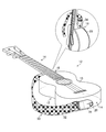
- FIG. 1 is a view showing an example of a strap pin 20 attached to a musical instrument 12.
- an instrument strap hereinafter simply referred to as a "strap" 30 is used. Therefore, the strap pin 20 for attaching the strap 30 is attached to the musical instrument 12.
- the strap 30 is provided with a strip-shaped member 32 which can be adjusted in length, and tongue-shaped mounting portions 34 provided at both ends of the strip-shaped member 32.
- a mounting hole 36 (see FIG. 3) described later is formed in the mounting portion 34, and the strap pin 20 is detachably mounted.
- the strap pins 20 are respectively provided at the end portion 14 of the body 13 of the musical instrument 12 and the heel portion 16 at the junction with the neck 15 on the opposite side of the end portion 14 of the body 13 of the musical instrument 12.
- the structure attached to is shown as an example, it is not limited to this structure.
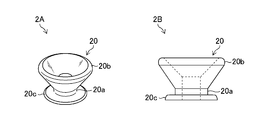
- FIG. 2 is a view showing an example of the strap pin 20.
- reference numeral 2 ⁇ / b> A shows a perspective view of the strap pin 20
- reference numeral 2 ⁇ / b> B shows a side view of the strap pin 20.
- the strap pin 20 spreads outward (in the radial direction orthogonal to the axial direction of the narrowed portion 20a) at the narrowed portion 20a having a circular cross section and the tip of the narrowed portion 20a.
- An enlarged diameter portion 20b having a square shape and an attachment portion (attachment plate) 20c provided on the opposite side of the enlarged diameter portion 20b of the constricted portion 20a and constituting an attachment surface with the musical instrument 12 are provided.
- the strap pins 20 are fixed to the musical instrument 12 by screws (not shown).
- the strap pin 20 may be of various shapes and sizes, but its overall features are substantially the same as those shown in FIG.
- FIG. 3 is a view showing an example of the mounting portion 34 of the strap 30.
- the mounting portion 34 of the strap 30 is provided with a mounting hole 36 for mounting the strap pin 20.
- a slit 38 is formed in connection with the mounting hole 36.
- the mounting hole 36 is expanded by the slit 38, and the enlarged diameter portion 20 b of the strap pin 20 is penetrated through the mounting hole 36 to position the constricted portion 20 a in the mounting hole 36.
- the slit 38 is fixed by narrowing at the constricted portion 20a and fixed by the enlarged diameter portion 20b so that the attached state of the strap 30 to the musical instrument 12 can be maintained.
- the player can use the strap 30 attached to the musical instrument 12 by suspending it with his shoulder when playing while standing.
- Patent Document 1 the reinforcing portion is superimposed on the strap mounting portion, and the strap mounting portion and the reinforcing portion at different positions where slits from the mounting hole (holding hole) are overlapped are mounted on the strap pin. Straps are disclosed.
- the strap disclosed in Patent Document 1 has a structure in which the strap can not be easily detached from the strap pin of the musical instrument as compared to the conventional strap (see FIG. 3), the strap is obtained by adopting this structure. It is difficult for the player to remove, and it is not convenient for the player. In addition, if the strap is repeatedly attached and removed, the attachment hole of the strap is necessarily slackened, the holding power of the instrument is weakened, and the instrument may be dropped.
- the present invention has been made in view of such circumstances, and an object thereof is to provide a strap pin fitting capable of easily attaching and detaching a strap to an instrument.
- a strap pin fitting includes a base plate, a strap holding portion disposed on the base plate for holding the strap, a through hole formed in the base plate and into which the strap pin can be inserted, and the base A holding plate attached to the plate, wherein the through hole is opened to allow insertion of the strap pin into the through hole, and a part of the through hole is closed to extract the strap pin from the through hole And a presser plate movable between a closed position that prevents movement.
- the presser plate is rotatably mounted about a direction orthogonal to the normal direction of the base plate.
- the presser plate is rotatably mounted centering on the normal direction of the base plate.
- a strap pin fitting according to a fourth aspect of the present invention comprises a biasing member for biasing the presser plate to the closed position in the second or third aspect.
- the through holes are formed by connecting a large hole portion and a small hole portion having mutually different hole diameters. Ru.
- the through hole is configured by one round hole.
- attachment and detachment of the strap to the musical instrument can be easily performed.
- FIG showing an example of strap pins attached to an instrument Figure showing an example of strap pin Figure showing an example of the strap attachment part The figure which showed the strap pin metal fitting which concerns on 1st Embodiment.
- the figure for demonstrating the connection method of the strap pin metal fitting and strap pin which concern on 1st Embodiment The figure for demonstrating the connection method of the strap pin metal fitting and strap pin which concern on 1st Embodiment.
- the figure which showed the strap pin metal fitting which is the development example of this invention The figure for demonstrating the connection method of the strap pin metal fitting and the strap pin which is the development example of this invention.
- the figure for demonstrating the connection method of the strap pin metal fitting and the strap pin which is the development example of this invention The figure for demonstrating the connection method of the strap pin metal fitting and the strap pin which is the development example of this invention.
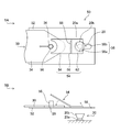
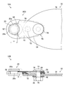
- FIG. 4 is a view showing the strap pin fitting 50 according to the first embodiment.
- reference numeral 4A indicates a plan view of the strap pin fitting 50
- reference numeral 4B indicates a side view of the strap pin fitting 50.
- the strap pin fitting 50 of the present embodiment is a connecting tool which is interposed between the strap pin 20 and the strap 30 to connect them and mainly includes the base plate 52 and the pressing plate 54. , Strap holder 56.
- the base plate 52 is formed of a flat member.
- the base plate 52 is formed with a through hole 58 into which the strap pin 20 can be inserted.
- the through holes 58 are configured by connecting large holes 58 a and small holes 58 b having different hole diameters.
- the large hole portion 58a has a substantially circular shape in a plan view.
- the small hole portion 58b has a long hole shape extending from the large hole portion 58a in the opposite direction to the strap holding portion 56.
- the large hole portion 58a is formed larger than the outer diameter of the enlarged diameter portion 20b of the strap pin 20, and is large enough to allow the enlarged diameter portion 20b of the strap pin 20 to be inserted.
- the small hole portion 58 b is formed larger than the outer diameter of the narrowed portion 20 a of the strap pin 20 and smaller than the outer diameter of the enlarged diameter portion 20 b of the strap pin 20. It has a size that can be inserted.
- the pressing plate 54 has a shape in which the rear side (the strap holding portion 56 side) in the front-rear direction (longitudinal direction of the base plate 52) is bent. That is, when the base plate 52 is viewed from the side, as shown by the reference numeral 4B in FIG. 4, the presser plate 54 has a substantially "H” shaped (substantially "L” shaped) shape. doing.
- the presser plate 54 is configured such that a front end portion 62 on the front side and a rear end portion 64 on the rear side are connected via a bending portion 66 which is a boundary portion.
- the pressing plate 54 is attached to the base plate 52 so as to be rotatable about a direction perpendicular to the normal direction of the base plate 52 as a rotation center.
- the holding plate 54 is mounted on a bending line along a direction orthogonal to the longitudinal direction of the base plate 52 via the hinge portion 68, and can rotate about a direction along the bending line as a rotation center It is in the state.
- the hinge portion 68 is composed of a spring-loaded hinge (corresponding to the “biasing member” of the present invention), and is biased in such a direction that the front end portion 62 of the pressing plate 54 is pressed against the base plate 52 by the biasing force of the spring. It is powered. That is, the front end portion 62 of the pressing plate 54 is urged by the spring of the hinge portion 68 to a closing position where the large hole portion 58a which is a part of the through hole 58 is closed.
- the strap holder 56 is formed of a cylindrical member disposed on the base plate 52.
- the strap holding portion 56 is formed in a size that can be inserted into the attachment hole 36 of the mounting portion 34 of the strap 30.
- the strap 30 is fixed to the strap holding portion 56 by inserting the strap holding portion 56 into the attachment hole 36 of the mounting portion 34 of the strap 30 and tightening and fixing with a screw (not shown).
- the mounting portion 34 of is connected.
- a cap may be fitted and connected to the tip of the strap holding portion 56, or the strap holding portion 56 and the mounting portion 34 of the strap 30 may be connected by a cord or the like.
- the strap holding portion 56 and the mounting portion 34 of the strap 30 may be connected using a pin, an E-ring or the like.
- the strap holding portion 56 is inserted through the mounting hole 36 of the mounting portion 34 of the strap 30 and a screw (not shown) Tighten and fix with.
- the strap pins 20 and the large holes 58a of the through holes 58 aligned the strap pins 20 are inserted through the through holes 58 from the lower surface side of the base plate 52.
- the enlarged diameter portion 20 b of the strap pin 20 can be inserted into the large hole portion 58 a of the through hole 58.
- the pressing plate naturally returns to the closed position where the large hole portion 58a of the through hole 58 is closed by the biasing force. As a result, the strap pin 20 does not fall out of the through hole 58, and the strap pin 50 and the strap pin 20 are securely coupled.
- the rear end portion 64 of the pressing plate 54 is pushed from above onto the base plate 52 to close the large hole 58 a of the through hole 58. Since the front end 62 moves from the closed position to the open position, the strap pin 20 can be slid to the large hole 58a to easily remove the strap pin 20 from the large hole 58a.
- the strap pin bracket 50 of the present embodiment is provided on the base plate 52 and the base plate 52, is formed on the strap holding portion 56 for holding the strap 30, and is formed on the base plate 52. And a holding plate 54 attached to the base plate 52.
- the holding plate 54 opens the through hole 58 to allow insertion of the strap pin 20 into the through hole 58. And the closed position for closing the part of the through hole 58 and blocking the withdrawal operation of the strap pin 20 from the through hole 58, the strap pin 50 and the strap pin 20 Coupling and decoupling can be performed easily and quickly.
- the strap 30 can be easily attached to and removed from the musical instrument 12 by connecting the strap 30 and the strap pin 20 with the strap pin fitting 50 interposed therebetween.
- the pressing plate 54 is biased to the closed position where the through hole 58 is closed by the biasing member (spring of the hinge portion 68).
- the present invention is not limited to this. Between a locked state in which the pressing plate 54 is fixed in the closed position and a non-locked state in which the pressing plate 54 is movable between the closed position and the open position using a locking mechanism (engagement mechanism) not shown. It may be switched.
- the configuration in which the base plate 52 is a flat plate member is shown as an example, but the present invention is not limited thereto.
- the base plate 52 is bent or curved in a mountain shape or valley shape along its longitudinal direction. It may be formed.
- the pressing plate 54 may be bent or curved in a mountain shape or a valley shape depending on the shape of the base plate 52. The same applies to a second embodiment and a development example described later.
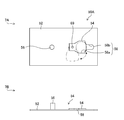
- FIG. 7 is a view showing a strap pin fitting 50A according to the second embodiment.
- components common or similar to those in FIG. 4 are assigned the same reference numerals.
- the second embodiment is the same as the first embodiment except that the configuration of the pressing plate 54 is different.
- the holding plate 54 in the second embodiment functions as an elastically deformable leaf spring.
- the pressing plate 54 is rotatable about the normal direction of the base plate 52 as a rotation center.
- symbol 69 has shown the rotating shaft part of the base board 52. As shown in FIG.
- the strap pin bracket 50A and the strap pin 20 are connected, the strap pin 20 and the large hole 58a of the through hole 58 are aligned as in the first embodiment described above.
- the strap pin 20 is inserted into the large hole portion 58 a of the through hole 58 from the lower surface side of the base plate 52.
- the pressing plate 54 functioning as a plate spring is curved and deformed by its elastic force. Meanwhile, the strap pin 20 can be inserted into the large hole portion 58 a of the through hole 58.
- the pressing plate 54 naturally becomes its original shape by its elastic force. Returning to the closed position where the large hole portion 58a of the through hole 58 is closed. As a result, the strap pin 20 does not fall out of the through hole 58, and the strap pin fitting 50A and the strap pin 20 are securely coupled.
- the pressing plate 54 When releasing the connection between the strap pin 20 and the strap pin bracket 50A, as shown by reference numeral 7A in FIG. 7, the pressing plate 54 is at an open position where the large hole portion 58a of the through hole 58 is opened The strap pin 20 can be removed from the through hole 58 by rotating it to the illustrated position).
- the musical instrument 12 is configured by connecting the strap 30 and the strap pin 20 with the strap pin bracket 50A interposed as in the first embodiment.
- the attachment and removal of the strap 30 can be easily performed.
- the pressing plate 54 has a function of closing the large hole portion 58a which is a part of the through hole 58 so as to prevent the strap pin 20 from coming off, the strength to support the musical instrument 12 is not necessary. It is also possible to cope with a thin plate member made of resin or metal thinner than the presser plate 54 of the first embodiment.
- the pressing plate 54 is configured to be rotatable around the rotation shaft portion 69, but the pressing plate 54 is a large hole portion of the through hole 58 by a biasing member (spring or the like) not shown. It is desirable to be biased in the closed position closing the 58a. Thereby, it is possible to prevent the connection between the strap pin 50A and the strap pin 20 from being released carelessly.
- a biasing member spring or the like
- the pressing plate 54 be provided with an operating portion such as a projection.
- the pressing plate 54 can be easily rotated, and the removal operation can be easily performed.
- the through holes 58 provided in the base plate 52 are configured such that the large holes 58 a and the small holes 58 b having different hole diameters are connected, but the shape of the through holes 58 is not necessarily Even if it is not a combination of large and small holes, it is possible to fulfill the purpose of the present invention.
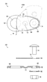
- FIG. 8 is a view showing a strap pin fitting 50B as a development example of the present invention.
- reference numeral 8A shows a plan view of the strap pin bracket 50B
- reference numeral 8B shows an exploded view of the strap pin bracket 50B.
- the same or similar components as or to those in FIG. 4 are denoted by the same reference numerals.
- the strap pin fitting 50B as a development example of the present invention has a generally rounded shape (substantially oval shape) from the viewpoint of design.
- the strap pin fitting 50B includes the base plate 52, the pressing plate 54, and the strap holding portion 56 in common with the above embodiments, but the shape of the through hole 58 formed in the base plate 52 Is a point that is constituted by a round hole in a plan view circular shape, a point that is greatly different from the above-described embodiments.
- the inner diameter of the through hole 58 is larger than the outer diameter of the enlarged diameter portion 20b of the strap pin 20 (see FIGS. 9 and 10).
- the pressing plate 54 has a shape substantially overlapping the base end side region (the region on the strap holding portion 56 side) of the base plate 52 when viewed in a plan view, as shown by reference numeral 8A in FIG. It is possible to rotate around the normal direction of 52 as the center of rotation.
- the pressing plate 54 is configured to close a part of the through hole 58 when disposed at a position (closing position) overlapping the base plate 52.
- the gap H formed between the through hole 58 and the pressing plate 54 is smaller than the outer diameter of the enlarged diameter portion 20 b of the strap pin 20 and larger than the outer diameter of the narrowed portion 20 a of the strap pin 20.
- the positional relationship and the size between the presser plate 54 and the through hole 58 are determined in such a manner as to become (see FIGS. 9 and 10).
- Recesses (recesses) 70 are provided on both sides (side surfaces) of the base plate 52, respectively. A non-overlapping region which does not overlap the base plate 52 is formed in the pressing plate 54 by the recessed portion 70, so that the pressing operation of the pressing plate 54 can be performed by pressing the pressing plate 54 corresponding to this region in the rotation direction. It becomes possible to carry out simply.
- a convex portion 72 having a circular shape in a plan view and protruding toward the side opposite to the pressing plate 54 is formed on the base plate 52 in an intermediate region corresponding to between the strap holding portion 56 and the through hole 58. There is.
- the convex portion 72 functions as a strap support portion that supports the tip end portion of the strap 30 when the strap 30 is attached to the strap pin fitting 50B.
- the strap holding portion 56 is a portion for fixing the strap 30 to the base plate 52 using the bolt 74 and the nut 76.
- the strap 30 When attaching the strap 30 to the strap holding portion 56, as shown in 9A and 9B of FIG. 9, it is provided on the proximal end side of the base plate 52 and the rotation hole 78 provided on the proximal end side of the pressing plate 54.
- the bolt insertion holes 80 and the mounting holes 36 of the straps 30 aligned so as to overlap each other in plan view, the bolts 74 are inserted through the holes from the side of the pressing plate 54 and project from the opposite side
- the tip end of the bolt 74 is tightened and fixed by a nut 76 via a washer 82.
- the nut 76 is tightened to such an extent that the pressing plate 54 can rotate with the rotation hole 78 as a fulcrum.
- the strap pin fitting 50B and the strap 30 are connected, and the pressing plate 54 can be rotated.
- the pressing plate 54 When connecting the strap pin bracket 50B and the strap pin 20, as shown by reference numerals 9A and 9B in FIG. 9, the pressing plate 54 is operated to rotate in a predetermined direction (for example, clockwise direction) to hold the pressing plate 54. Move to the open position. Then, the strap pin 20 is inserted into the through hole 58 of the base plate 52. Next, as shown by reference numerals 10A and 10B in FIG. 10, the pressing plate 54 is rotated in the reverse direction (for example, counterclockwise direction), and the pressing plate 54 is in the original state, that is, the pressing plate 54 is in the closed position. Move it.
- a predetermined direction for example, clockwise direction
- the narrow portion 20a of the strap pin 20 inserted into the through hole 58 of the base plate 52 is disposed in the gap H formed between the through hole 58 and the pressing plate 54, so that the strap pin 20 does not fall out of the through hole 58, and the strap pin fitting 50B and the strap pin 20 are securely coupled.
- the through hole 58 provided in the base plate 52 is configured by one hole portion, and the pressing plate 54 is rotated. 54 can be configured to be switchable between a closed position where the through hole 58 is partially closed and an open position where the through hole 58 is opened. Therefore, attachment and detachment of the strap 30 to the musical instrument 12 can be easily performed by connecting the strap 30 and the strap pin 20 with the strap pin fitting 50B interposed therebetween, and the above-described embodiments. The same effect can be obtained.
- the pressing plate 54 is configured to be switchable between the closing position for closing a part of the through hole 58 and the opening position for opening the through hole 58 by the rotation operation of the pressing plate 54.
- the present invention is not limited to this configuration.
- the presser plate 54 may be formed of a thin resin or metal thin plate member and the presser plate 54 may function as an elastically deformable leaf spring. . According to this configuration, it is possible to connect the strap pin fitting 50B and the strap pin 20 in the same manner as in the second embodiment described above without rotating the pressing plate 54.
- the strap pins 20 are inserted into the through holes 58 from the lower surface side of the base plate 52.
- the pressing plate 54 functioning as a leaf spring bends and deforms the strap pin 20 while being bent and deformed. It can be inserted into the through hole 58.
- the presser plate When the narrow portion 20a of the strap pin 20 is slid to the edge of the through hole 58 (the edge opposite to the strap holding portion 56) after being inserted to the narrow portion 20a of the strap pin 20, the presser plate The spring 54 naturally returns to its original shape due to its elastic force, and returns to the closed position where the through hole 58 is partially closed. As a result, the strap pin 20 does not fall out of the through hole 58, and the strap pin fitting 50B and the strap pin 20 are securely coupled.
- the strap pin 20 can be removed from the through hole 58 by rotating the presser plate 54 as in the above-described embodiment. It becomes.
- the through-hole 58 provided in the base plate 52 is comprised by the round hole of planar view circular shape was shown as an example of a preferable aspect in the development mentioned above, it does not restrict to this, for example, elliptical shape It may be polygonal, or any other shape.
Landscapes
- Engineering & Computer Science (AREA)
- General Engineering & Computer Science (AREA)
- Physics & Mathematics (AREA)
- Acoustics & Sound (AREA)
- Multimedia (AREA)
- Mechanical Engineering (AREA)
- Auxiliary Devices For Music (AREA)
- Purses, Travelling Bags, Baskets, Or Suitcases (AREA)
- Snaps, Bayonet Connections, Set Pins, And Snap Rings (AREA)
- Stringed Musical Instruments (AREA)
Abstract
楽器に対するストラップの取り付け及び取り外しを簡単に行うことができるストラップピン金具を提供する。ストラップピン金具50は、ベース板52と、ベース板52に配設され、ストラップ30を保持するストラップ保持部56と、ベース板52に形成され、ストラップピン20を挿入可能な貫通孔58と、ベース板52に取り付けられた押え板54と、を備える。この押え板54は、貫通孔58を開放して貫通孔58へのストラップピン20の挿入動作を許容する開放位置と、貫通孔58の一部を閉鎖して貫通孔58からストラップピン20の抜出動作を阻止する閉鎖位置との間で移動可能に構成される。
Description
本発明は、ギターなどの楽器にストラップを取り付けるためのストラップピン金具に関するものである。
図1は、楽器12に取り付けられたストラップピン20の一例を示した図である。図1に示すように、ギターなどの楽器12は、立った状態で演奏する場合、楽器用ストラップ(以下、単に「ストラップ」)30が使用される。そのため、楽器12には、ストラップ30を装着するためのストラップピン20が取り付けられている。ストラップ30は、長さ調節可能な帯状部材32と、帯状部材32の両端に設けられた舌片状の装着部34とを備えている。装着部34には後述する取付孔36(図3参照)が形成されており、ストラップピン20が着脱自在に取り付けられる。なお、図1では、ストラップピン20は、楽器12のボディ13のエンド部14と、楽器12のボディ13のエンド部14の反対側で、ネック15との接合部にあるヒール部16とにそれぞれに取り付けられた構成を一例として示したが、この構成に限定されるものではない。
図2は、ストラップピン20の一例を示した図である。図2において、符号2Aはストラップピン20の斜視図を示し、符号2Bはストラップピン20の側面図を示している。図2の符号2A及び2Bに示すように、ストラップピン20は、断面円形状の括れ部20aと、括れ部20aの先端に(括れ部20aの軸方向に直交する径方向の)外向きに広がった形状を有する拡径部20bと、括れ部20aの拡径部20bとは反対側に設けられ、楽器12との取付面を構成する取付部(取付板)20cとを備えている。ストラップピン20は、楽器12に図示しないネジによりネジ止め固定される。なお、ストラップピン20には様々な形状及び大きさのものがあるが、その全体的な特徴は図2に示したものとほぼ同様である。
図3は、ストラップ30の装着部34の一例を示した図である。図3に示すように、ストラップ30の装着部34には、ストラップピン20を取り付けるための取付孔36が設けられている。この取付孔36には、スリット38がつながって形成されている。楽器12にストラップ30を装着する場合には、スリット38で取付孔36を広げつつ、取付孔36にストラップピン20の拡径部20bを貫通させ、取付孔36に括れ部20aを位置させることにより、括れ部20aでスリット38が狭まることで固定し、かつ拡径部20bによって抜け止めを図り、楽器12に対するストラップ30の装着状態を維持することができるようになっている。これにより、演奏者は、立った状態で演奏する場合、楽器12に装着されたストラップ30を肩で吊り下げるようにして使用することができる。
しかしながら、図3に示したストラップ30の装着部34では、ストラップピン20を取り付けるための取付孔36とスリット38とがつながっているため、楽器12に設けられたストラップピン20からストラップ30が外れて脱落しやすい問題がある。
かかる問題に対し、特許文献1では、ストラップ装着部の上に補強部を重ね合わせ、取付孔(保持孔)からのスリットが入る位置が異なるストラップ装着部と補強部とを重ねてストラップピンへ装着する構成としたストラップが開示されている。
ところで、演奏者が演奏を終えて楽器をしまうとき、体に固定した楽器のストラップをストラップピンから外して片づける。そして、再び演奏を始めるときには、ストラップを肩にかけ、ストラップの取付孔を楽器のストラップピンに取り付けて準備をする。同様に、楽器を変える場合にも、ストラップの取り付け及び取り外しが必要になる。
特許文献1に開示されたストラップでは、従来のストラップ(図3参照)に比べて、楽器のストラップピンからストラップが外れ難い構造となっているものの、逆に、この構造を採用したことにより、ストラップの取り外しが困難なものとなっており、演奏者にとって利便性に欠けたものとなっている。また、ストラップの取り付け及び取り外しを繰り返すとどうしても、ストラップの取付孔が弛んでしまい、楽器の保持力が弱くなり、楽器の落下の恐れも出てくる。
本発明は、このような事情に鑑みてなされたもので、楽器に対するストラップの取り付け及び取り外しを簡単に行うことができるストラップピン金具を提供することを目的とする。
上記目的を達成するために、以下の発明を提供する。
本発明の第1態様に係るストラップピン金具は、ベース板と、ベース板に配設され、ストラップを保持するストラップ保持部と、ベース板に形成され、ストラップピンを挿入可能な貫通孔と、ベース板に取り付けられた押え板であって、貫通孔を開放して貫通孔へのストラップピンの挿入動作を許容する開放位置と、貫通孔の一部を閉鎖して貫通孔からストラップピンの抜出動作を阻止する閉鎖位置との間で移動可能な押え板と、を備える。
本発明の第2態様に係るストラップピン金具は、第1態様において、押え板は、ベース板の法線方向に直交する方向を回転中心に回転可能に取り付けられている。
本発明の第3態様に係るストラップピン金具は、第1態様において、押え板は、ベース板の法線方向を回転中心に回転可能に取り付けられている。
本発明の第4態様に係るストラップピン金具は、第2態様又は第3態様において、押え板を閉鎖位置に付勢する付勢部材を備える。
本発明の第5態様に係るストラップピン金具は、第1態様から第4態様のいずれか1つの態様において、貫通孔は、互いに孔径が異なる大孔部と小孔部とが連結して構成される。
本発明の第6態様に係るストラップピン金具は、第1態様から第4態様のいずれか1つの態様において、貫通孔は、1つの丸孔で構成される。
本発明によれば、楽器に対するストラップの取り付け及び取り外しを簡単に行うことができる。
以下、添付図面に従って本発明の好ましい実施の形態について詳説する。
(第1の実施形態)
図4は、第1の実施形態に係るストラップピン金具50を示した図である。図4において、符号4Aはストラップピン金具50の平面図を示し、符号4Bはストラップピン金具50の側面図を示している。
図4は、第1の実施形態に係るストラップピン金具50を示した図である。図4において、符号4Aはストラップピン金具50の平面図を示し、符号4Bはストラップピン金具50の側面図を示している。
図4に示すように、本実施形態のストラップピン金具50は、ストラップピン20とストラップ30との間に介在して両者を接続する接続具であり、主として、ベース板52と、押え板54と、ストラップ保持部56とを備えている。
ベース板52は、平板状部材により構成される。ベース板52には、ストラップピン20を挿入可能な貫通孔58が形成されている。この貫通孔58は、互いに孔径が異なる大孔部58aと小孔部58bとが連結して構成される。図4の符号4Aに示すように、平面視で、大孔部58aは略円形状の形状を有している。また、小孔部58bは、大孔部58aからストラップ保持部56とは反対方向に延びる長孔状の形状を有している。
大孔部58aは、ストラップピン20の拡径部20bの外径よりも大きく形成されており、ストラップピン20の拡径部20bを挿通可能な大きさとなっている。
小孔部58bは、ストラップピン20の括れ部20aの外径よりも大きく、かつストラップピン20の拡径部20bの外径よりも小さく形成されており、ストラップピン20のうち括れ部20aのみを挿通可能な大きさとなっている。
押え板54は、前後方向(ベース板52の長手方向)の後側(ストラップ保持部56側)が屈曲した形状を有している。すなわち、押え板54は、図4の符号4Bに示すように、ベース板52を側方向から見たときに、全体として略「へ」の字状(略「L」字状)の形状を有している。この押え板54は、前側の前端部62と後側の後端部64とがその境界部である屈曲部66を介して接続された構成となっている。
さらに、この押え板54は、ベース板52の法線方向に直交する方向を回転中心に回転可能にベース板52に取り付けられている。具体的には、ベース板52の長手方向に直交する方向に沿った屈曲線上にヒンジ部68を介して押え板54は取り付けられており、その屈曲線に沿った方向を回転中心として回転可能な状態となっている。このヒンジ部68はバネ付きヒンジ(本発明の「付勢部材」に相当)から構成され、そのバネの有する付勢力によって、押え板54の前端部62がベース板52に押さえ付けられる方向に付勢されている。つまり、押え板54の前端部62は、ヒンジ部68のバネにより貫通孔58の一部である大孔部58aを閉鎖する閉鎖位置に付勢された状態となっている。
このように押え板54の前端部62がヒンジ部68のバネにより閉鎖位置に付勢された状態で、そのバネの付勢力に抗して押え板54を押し操作(前端部62を下側から押圧あるいは後端部64を上側から押圧)すると、押え板54の前端部62は、貫通孔58の大孔部58aを開放する開放位置に移動し、貫通孔58の大孔部58aにストラップピン20を挿入可能な状態となる。
ストラップ保持部56は、ベース板52に配設された円柱状部材から構成される。ストラップ保持部56は、ストラップ30の装着部34の取付孔36に挿通可能な大きさに形成されている。ストラップ保持部56にストラップ30を固定する場合には、ストラップ30の装着部34の取付孔36にストラップ保持部56を挿通して図示しないネジで締付け固定することで、ストラップ保持部56にストラップ30の装着部34を連結する。あるいは、ストラップ保持部56の先端にキャップを嵌合して連結してもよいし、紐などでストラップ保持部56とストラップ30の装着部34とを連結してもよい。また、ピンやEリング等を用いてストラップ保持部56とストラップ30の装着部34とを連結してもよい。
以上のような構成を有するストラップピン金具50を用いて楽器12にストラップ30を取り付ける場合には、最初に、ストラップ30の装着部34の取付孔36にストラップ保持部56を挿通して図示しないネジで締付け固定しておく。次に、図5の符号5A及び5Bに示すように、ストラップピン20と貫通孔58の大孔部58aとの位置合わせをした状態で、ベース板52の下面側からストラップピン20を貫通孔58の大孔部58aを挿入する。このとき、ヒンジ部68のバネの有する付勢力によって閉鎖位置に付勢された押え板54の前端部62をストラップピン20で押し込むことで、押え板54の前端部62は開放位置に移動し、貫通孔58の大孔部58aにストラップピン20の拡径部20bを挿入することができる。そして、ストラップピン20の括れ部20aまで差し込んだ後、図6の符号6A及び6Bに示すように、ストラップピン20の括れ部20aを貫通孔58の小孔部58bまでスライド移動させると、バネの付勢力で自然に押え板54は貫通孔58の大孔部58aを閉鎖する閉鎖位置に復帰する。これにより、ストラップピン20は貫通孔58から抜け落ちることなく、ストラップピン金具50とストラップピン20とが確実に連結された状態となる。
また、演奏を終えて楽器12を取り外す時は、押え板54の後端部64を上方からベース板52に向かって押し込むことで、貫通孔58の大孔部58aを塞いでいる押え板54の前端部62が閉鎖位置から開放位置に移動するので、ストラップピン20を大孔部58a側にスライド移動させて、大孔部58aからストラップピン20を容易に取り外すことができる。
以上のとおり、本実施形態のストラップピン金具50は、ベース板52と、ベース板52に配設され、ストラップ30を保持するストラップ保持部56と、ベース板52に形成され、ストラップピン20を挿入可能な貫通孔58と、ベース板52に取り付けられた押え板54とを備え、この押え板54は、貫通孔58を開放して貫通孔58へのストラップピン20の挿入動作を許容する開放位置と、貫通孔58の一部を閉鎖して貫通孔58からストラップピン20の抜出動作を阻止する閉鎖位置との間で移動可能に構成されるので、ストラップピン金具50とストラップピン20との連結及び連結解除を容易かつ迅速に行うことができる。これにより、ストラップ30とストラップピン20との間をストラップピン金具50を介在させて接続した構成とすることにより、楽器12に対するストラップ30の取り付け及び取り外しを簡単に行うことができる。
なお、本実施形態では、押え板54を付勢部材(ヒンジ部68のバネ)により貫通孔58の一部を閉鎖する閉鎖位置に付勢する態様を示したが、これに限らず、例えば、図示しないロック機構(係合機構)を用いて、押え板54を閉鎖位置に固定したロック状態と、押え板54を閉鎖位置と開放位置との間で移動可能とした非ロック状態との間で切り替えられるようにしてもよい。
また、本実施形態では、ベース板52が平板状部材からなる構成を一例として示したが、これに限らず、例えば、ベース板52はその長手方向に沿って山状又は谷状に屈曲又は湾曲して形成されていてもよい。また、押え板54は、ベース板52の形状に応じて山状又は谷状に屈曲又は湾曲して形成されていてもよい。後述する第2の実施形態及び発展例においても同様である。
(第2の実施形態)
次に、本発明の第2の実施形態について説明する。以下、上述した第1の実施形態と共通する部分については説明を省略し、本実施形態の特徴的部分を中心に説明する。
次に、本発明の第2の実施形態について説明する。以下、上述した第1の実施形態と共通する部分については説明を省略し、本実施形態の特徴的部分を中心に説明する。
図7は、第2の実施形態に係るストラップピン金具50Aを示した図である。なお、図7中、図4と共通又は類似する構成要素には同一の番号を付している。
第2の実施形態は、押え板54の構成が異なる点を除いて第1の実施形態と同様である。具体的には、第2の実施形態における押え板54は、弾性変形可能な板バネとして機能するようになっている。また、この押え板54は、ベース板52の法線方向を回転中心に回転可能な状態となっている。なお、符号69は、ベース板52の回転軸部を示している。
本実施形態において、ストラップピン金具50Aとストラップピン20とを連結する場合には、上述した第1の実施形態と同様に、ストラップピン20と貫通孔58の大孔部58aとの位置合わせをした状態で、ベース板52の下面側からストラップピン20を貫通孔58の大孔部58aに挿入する。このとき、ストラップピン20で押え板54を押し込みながら貫通孔58の大孔部58aにストラップピン20を差し込んでいくと、板バネとして機能する押え板54は、その弾性力によって湾曲して変形しながらストラップピン20を貫通孔58の大孔部58aに挿入することができる。そして、ストラップピン20の括れ部20aまで差し込んだ後、ストラップピン20の括れ部20aを貫通孔58の小孔部58bまでスライド移動させると、押え板54はその弾性力によって自然に元の形状に戻り、貫通孔58の大孔部58aを閉鎖する閉鎖位置に復帰する。これにより、ストラップピン20は貫通孔58から抜け落ちることなく、ストラップピン金具50Aとストラップピン20とが確実に連結された状態となる。
ストラップピン20とストラップピン金具50Aとの連結を解除する場合には、図7の符号7Aに示すように、押え板54を貫通孔58の大孔部58aを開放する開放位置(2点鎖線で図示)まで回転させることにより、ストラップピン20を貫通孔58から取り外すことが可能となる。
したがって、本実施形態のストラップピン金具50Aにおいても、第1の実施形態と同様に、ストラップ30とストラップピン20との間をストラップピン金具50Aを介在させて接続した構成とすることにより、楽器12に対するストラップ30の取り付け及び取り外しを簡単に行うことができる。
なお、本実施形態において、押え板54は、ストラップピン20が抜けないように貫通孔58の一部である大孔部58aを閉鎖する機能があれば、楽器12を支える強度は必要ないので、第1の実施形態の押え板54よりも厚みの薄い樹脂製又は金属製の薄板状部材でも対応可能である。
また、本実施形態において、押え板54は回転軸部69を回転中心として回転可能な構成となっているが、押え板54は図示しない付勢部材(バネ等)により貫通孔58の大孔部58aを閉鎖する閉鎖位置に付勢されていることが望ましい。これにより、ストラップピン金具50Aとストラップピン20との連結が不用意に解除されることを防止することができる。
また、本実施形態において、押え板54には突起などの操作部が設けられていることが望ましい。これにより、ストラップピン20からストラップピン金具50Aを取り外す際に、押え板54の回転操作を容易に行うことができ、取り外し作業を簡単に行うことが可能となる。
(発展例)
次に、本発明の発展例を説明する。上述した各実施形態では、ベース板52に設けられる貫通孔58は、互いに孔径が異なる大孔部58aと小孔部58bとが連結された構成としたが、貫通孔58の形状は必ずしもこのような大小の孔部の組み合わせでなくても本発明の目的の機能を果たすことが可能である。
次に、本発明の発展例を説明する。上述した各実施形態では、ベース板52に設けられる貫通孔58は、互いに孔径が異なる大孔部58aと小孔部58bとが連結された構成としたが、貫通孔58の形状は必ずしもこのような大小の孔部の組み合わせでなくても本発明の目的の機能を果たすことが可能である。
図8は、本発明の発展例としてのストラップピン金具50Bを示した図である。図8において、符号8Aはストラップピン金具50Bの平面図を示し、符号8Bはストラップピン金具50Bの分解組立図を示している。なお、図8中、図4と共通又は類似する構成要素には同一の番号を付している。
図8の符号8Aに示すように、本発明の発展例としてのストラップピン金具50Bは、デザイン性の観点から、全体的に丸みをおびた形状のもの(略卵型形状)となっている。
このストラップピン金具50Bは、ベース板52と、押え板54と、ストラップ保持部56とを備える点は上述した各実施形態と共通しているが、ベース板52に形成される貫通孔58の形状が平面視円形状の丸孔によって構成される点が上述した各実施形態とは大きく異なる点である。この貫通孔58の内径は、ストラップピン20の拡径部20bの外径よりも大きく形成されている(図9及び図10参照)。
押え板54は、図8の符号8Aに示すように、平面視したときに、ベース板52の基端側領域(ストラップ保持部56側の領域)とほぼ重なる形状を有し、かつ、ベース板52の法線方向を回転中心に回転可能な状態となっている。この押え板54は、ベース板52と重なる位置(閉鎖位置)に配置されたときには貫通孔58の一部を塞ぐようになっている。このとき、貫通孔58と押え板54との間に形成される隙間Hがストラップピン20の拡径部20bの外径よりも小さく、かつ、ストラップピン20の括れ部20aの外径よりも大きくなるように、押え板54と貫通孔58との位置関係や大きさが定められている(図9及び図10参照)。
したがって、押え板54の回転操作により、押え板54が貫通孔58を開放する開放位置に配置された場合には、貫通孔58へのストラップピン20の挿入動作が許容された状態となる。一方、貫通孔58にストラップピン20が挿入された状態で、押え板54の回転操作により、押え板54が貫通孔58の一部を閉鎖する閉鎖位置に配置された場合には、貫通孔58と押え板54との間に形成される隙間Hが上述した大きさとなるように設定されているので、貫通孔58からストラップピン20の抜出動作が阻止された状態となる。
ベース板52の両脇(両側面)には、それぞれ窪み部(凹部)70が設けられている。この窪み部70により、押え板54にはベース板52と重ならない非重なり領域が形成されるので、この領域に対応する押え板54をその回転方向に押し込むことにより、押え板54の回転操作を簡便に行うことが可能となる。
また、ベース板52には、ストラップ保持部56と貫通孔58との間に相当する中間領域に、押え板54とは反対側に向かって突出する平面視円形状の凸部72が形成されている。この凸部72は、ストラップピン金具50Bにストラップ30が取り付けられた場合に、ストラップ30の先端部を支持するストラップ支持部として機能する。
ストラップ保持部56は、ボルト74とナット76を用いてストラップ30をベース板52に固定する部分である。ストラップ保持部56にストラップ30を取り付ける場合には、図9の9A及び9Bに示すように、押え板54の基端側に設けられた回転孔78と、ベース板52の基端側に設けられたボルト挿通用孔80と、ストラップ30の取付孔36とを、平面視で互いに重なるように位置合わせをした状態で、押え板54側から各孔にボルト74を挿通し、その反対側から突出したボルト74の先端部をワッシャー82を介してナット76によって締め付け固定する。このとき、押え板54が回転孔78を支点として回転可能な程度にナット76を締め付けておく。これにより、ストラップピン金具50Bとストラップ30とが連結された状態となるとともに、押え板54の回転操作が可能となる。
ストラップピン金具50Bとストラップピン20とを連結する場合には、図9の符号9A及び9Bに示すように、押え板54を所定の方向(例えば時計周り方向)に回転操作し、押え板54を開放位置に移動させる。そして、ベース板52の貫通孔58にストラップピン20を挿入する。次に、図10の符号10A及び10Bに示すように、押え板54を逆方向(例えば反時計周り方向)に回転操作し、押え板54を元の状態、すなわち、押え板54を閉鎖位置に移動させる。これにより、ベース板52の貫通孔58に挿入されたストラップピン20の括れ部20aは、貫通孔58と押え板54との間に形成される隙間Hに配置されるようになるので、ストラップピン20は貫通孔58から抜け落ちることなく、ストラップピン金具50Bとストラップピン20とが確実に連結された状態となる。
なお、ストラップピン金具50Bとストラップピン20との連結を解除する場合には、逆の手順を行えばよいので、説明の重複を避けるためその説明を省略する。
以上のように、本発明の発展例であるストラップピン金具50Bによれば、ベース板52に設けられる貫通孔58が1つの孔部で構成されており、押え板54の回転操作により、押え板54を、貫通孔58の一部を閉鎖する閉鎖位置と、貫通孔58を開放する開放位置との間で切り替え可能に構成することができる。したがって、ストラップ30とストラップピン20との間をストラップピン金具50Bを介在させて接続した構成とすることにより、楽器12に対するストラップ30の取り付け及び取り外しを簡単に行うことができ、上述した各実施形態と同様の効果を得ることができる。
また、上述した発展例では、押え板54の回転操作により、押え板54を、貫通孔58の一部を閉鎖する閉鎖位置と、貫通孔58を開放する開放位置との間で切り替え可能に構成したが、この構成に限定されず、例えば、押え板54を厚みの薄い樹脂製又は金属製の薄板状部材で構成し、押え板54を弾性変形可能な板バネとして機能させるようにしてもよい。この構成によれば、押え板54を回転操作することなく、上述した第2の実施形態と同様の手順で、ストラップピン金具50Bとストラップピン20とを連結することが可能である。すなわち、ストラップピン20と貫通孔58との位置合わせをした状態で、ベース板52の下面側からストラップピン20を貫通孔58に挿入する。このとき、ストラップピン20で押え板54を押し込みながら貫通孔58にストラップピン20を差し込んでいくと、板バネとして機能する押え板54は、その弾性力によって湾曲して変形しながらストラップピン20を貫通孔58に挿入することができる。そして、ストラップピン20の括れ部20aまで差し込んだ後、ストラップピン20の括れ部20aを貫通孔58の縁部(ストラップ保持部56側とは反対側の縁部)までスライド移動させると、押え板54はその弾性力によって自然に元の形状に戻り、貫通孔58の一部を閉鎖する閉鎖位置に復帰する。これにより、ストラップピン20は貫通孔58から抜け落ちることなく、ストラップピン金具50Bとストラップピン20とが確実に連結された状態となる。
なお、ストラップピン20とストラップピン金具50Bとの連結を解除する場合には、上述した発展例と同様に、押え板54を回転操作することにより、ストラップピン20を貫通孔58から取り外すことが可能となる。
また、上述した発展例では、好ましい態様の一例として、ベース板52に設けられる貫通孔58が平面視円形状の丸孔によって構成される場合を示したが、これに限らず、例えば、楕円状、多角形状、その他形状であってもよい。
以上、本発明の実施形態及びその発展例について説明したが、本発明は、以上の例には限定されず、本発明の要旨を逸脱しない範囲において、各種の改良や変形を行ってもよいのはもちろんである。
12…楽器、13…ボディ、14…エンド部、15…ネック、16…ヒール部、20…ストラップピン、20a…括れ部、20b…拡径部、20c…取付部、30…ストラップ、32…帯状部材、34…装着部、36…取付孔、38…スリット、50…ストラップピン金具、52…ベース板、54…押え板、56…ストラップ保持部、58…貫通孔、58a…大孔部、58b…小孔部、62…前端部、64…後端部、66…屈曲部、68…ヒンジ部、69…回転軸部、70…窪み部、72…凸部、74…ボルト、76…ナット、78…回転孔、80…ボルト挿通用孔、82…ワッシャー
Claims (6)
- ベース板と、
前記ベース板に配設され、ストラップを保持するストラップ保持部と、
前記ベース板に形成され、ストラップピンを挿入可能な貫通孔と、
前記ベース板に取り付けられた押え板であって、前記貫通孔を開放して前記貫通孔への前記ストラップピンの挿入動作を許容する開放位置と、前記貫通孔の一部を閉鎖して前記貫通孔から前記ストラップピンの抜出動作を阻止する閉鎖位置との間で移動可能な押え板と、
を備える、ストラップピン金具。 - 前記押え板は、前記ベース板の法線方向に直交する方向を回転中心に回転可能に取り付けられている、
請求項1に記載のストラップピン金具。 - 前記押え板は、前記ベース板の法線方向を回転中心に回転可能に取り付けられている、
請求項1に記載のストラップピン金具。 - 前記押え板を前記閉鎖位置に付勢する付勢部材を備える、
請求項2又は3に記載のストラップピン金具。 - 前記貫通孔は、互いに孔径が異なる大孔部と小孔部とが連結して構成される、
請求項1から4のいずれか1項に記載のストラップピン金具。 - 前記貫通孔は、1つの丸孔で構成される、
請求項1から4のいずれか1項に記載のストラップピン金具。
Priority Applications (3)
| Application Number | Priority Date | Filing Date | Title |
|---|---|---|---|
| EP18873621.9A EP3690261A4 (en) | 2017-10-31 | 2018-10-29 | BELT PIN FITTING |
| CN201880070569.1A CN111295526A (zh) | 2017-10-31 | 2018-10-29 | 背带钉金属配件 |
| US16/860,600 US10971120B2 (en) | 2017-10-31 | 2020-04-28 | Strap pin fitting |
Applications Claiming Priority (2)
| Application Number | Priority Date | Filing Date | Title |
|---|---|---|---|
| JP2017-211053 | 2017-10-31 | ||
| JP2017211053A JP6750828B2 (ja) | 2017-10-31 | 2017-10-31 | ストラップピン金具 |
Related Child Applications (1)
| Application Number | Title | Priority Date | Filing Date |
|---|---|---|---|
| US16/860,600 Continuation US10971120B2 (en) | 2017-10-31 | 2020-04-28 | Strap pin fitting |
Publications (1)
| Publication Number | Publication Date |
|---|---|
| WO2019088018A1 true WO2019088018A1 (ja) | 2019-05-09 |
Family
ID=66331807
Family Applications (1)
| Application Number | Title | Priority Date | Filing Date |
|---|---|---|---|
| PCT/JP2018/040093 Ceased WO2019088018A1 (ja) | 2017-10-31 | 2018-10-29 | ストラップピン金具 |
Country Status (5)
| Country | Link |
|---|---|
| US (1) | US10971120B2 (ja) |
| EP (1) | EP3690261A4 (ja) |
| JP (1) | JP6750828B2 (ja) |
| CN (1) | CN111295526A (ja) |
| WO (1) | WO2019088018A1 (ja) |
Cited By (1)
| Publication number | Priority date | Publication date | Assignee | Title |
|---|---|---|---|---|
| USD952734S1 (en) * | 2019-03-21 | 2022-05-24 | Bmg Works, Llc | Guitar strap with tortoiseshell tri-glide adjuster |
Families Citing this family (4)
| Publication number | Priority date | Publication date | Assignee | Title |
|---|---|---|---|---|
| JP6750828B2 (ja) * | 2017-10-31 | 2020-09-02 | 後藤ガット有限会社 | ストラップピン金具 |
| US11540649B2 (en) * | 2020-04-14 | 2023-01-03 | Dorel Juvenile Group, Inc. | Carry handle anchor system |
| JP7276693B2 (ja) * | 2020-09-09 | 2023-05-18 | カシオ計算機株式会社 | 鍵盤楽器 |
| US12272340B2 (en) * | 2022-03-16 | 2025-04-08 | Mark Ranalli | Guitar strap locking system |
Citations (6)
| Publication number | Priority date | Publication date | Assignee | Title |
|---|---|---|---|---|
| US828573A (en) * | 1905-12-18 | 1906-08-14 | I B Kleinert Rubber Co | Garment-hanger. |
| JPS63157324U (ja) * | 1987-04-02 | 1988-10-14 | ||
| JPH09140439A (ja) * | 1995-11-17 | 1997-06-03 | Asahi Optical Co Ltd | ストラップ用吊り金具 |
| JP2004183739A (ja) * | 2002-12-02 | 2004-07-02 | Masatoshi Yasunori | 取付具 |
| JP2013217991A (ja) | 2012-04-05 | 2013-10-24 | Takashi Kunii | 楽器用ストラップ |
| US20170206871A1 (en) * | 2016-01-15 | 2017-07-20 | D'addario & Company, Inc. | Locking Strap Mechanism |
Family Cites Families (24)
| Publication number | Priority date | Publication date | Assignee | Title |
|---|---|---|---|---|
| US808573A (en) * | 1905-03-21 | 1905-12-26 | James S Patten | Journal-box. |
| JPS3523275Y1 (ja) * | 1958-10-28 | 1960-09-14 | Yashica | |
| US3512226A (en) * | 1968-03-12 | 1970-05-19 | Textron Inc | Plastic hook and eye |
| JPS5217597Y2 (ja) * | 1973-03-16 | 1977-04-20 | ||
| JPS5083460U (ja) * | 1973-11-09 | 1975-07-17 | ||
| US4144794A (en) * | 1978-06-09 | 1979-03-20 | Silverman Allen B | Device for and method of removably securing a harness to a musical instrument |
| US4993127A (en) * | 1989-09-29 | 1991-02-19 | Standtastic | Locking attachment for guitar straps and the like |
| JP2780080B2 (ja) * | 1995-06-21 | 1998-07-23 | 後藤ガット有限会社 | ハーネスと弦楽器との連結装置 |
| US6080922A (en) * | 1997-08-28 | 2000-06-27 | Dimbath; Wolfgang | Disengageable belt attachment and in particular shoulder strap for portable musical instruments and for preferably guitars |
| US6032339A (en) * | 1999-03-03 | 2000-03-07 | Innovative Automation, Inc. | Locking fastener for a strap |
| US6259009B1 (en) * | 1999-07-29 | 2001-07-10 | Bolopick | Strap locking and pick storage device |
| CN100364830C (zh) * | 2002-11-21 | 2008-01-30 | 阿普丽佳葛西株式会社 | 育儿用具 |
| US7562422B2 (en) * | 2004-06-28 | 2009-07-21 | Innovative Automation, Inc. | Locking fastener for a strap |
| US20060081112A1 (en) * | 2004-10-18 | 2006-04-20 | Gipson Howard K | Device(s) for and method(s) of adapting and retaining straps |
| US7256337B1 (en) * | 2005-12-30 | 2007-08-14 | Timothy John Walker | Combination guitar pick and shoulder strap lock |
| US7888572B2 (en) * | 2007-01-05 | 2011-02-15 | Gibson Guitar Corp. | Guitar strap lock |
| US7818851B2 (en) * | 2007-07-25 | 2010-10-26 | Chris Perrotta | Strap lock |
| US20110136359A1 (en) * | 2009-12-09 | 2011-06-09 | Ronald Derrick Gregg | Guitar end pin jack plug |
| USD637942S1 (en) * | 2010-08-20 | 2011-05-17 | Ossur Hf | Strap retainer |
| US8920092B2 (en) * | 2011-04-18 | 2014-12-30 | D'addario & Company, Inc. | Rotatable end pin for instrument strap |
| US9589547B2 (en) * | 2014-07-25 | 2017-03-07 | Hogjim, LLC | Releasably securable end piece |
| US9947303B1 (en) * | 2016-02-12 | 2018-04-17 | Michael H. Dulin | Adapter device for attaching a strap to a musical instrument provided with a strap button |
| CN106952635B (zh) * | 2017-05-22 | 2023-08-25 | 东莞市华锦礼品有限公司 | 便携式自锁吉他带头及其自锁方法 |
| JP6750828B2 (ja) * | 2017-10-31 | 2020-09-02 | 後藤ガット有限会社 | ストラップピン金具 |
-
2017
- 2017-10-31 JP JP2017211053A patent/JP6750828B2/ja not_active Expired - Fee Related
-
2018
- 2018-10-29 EP EP18873621.9A patent/EP3690261A4/en not_active Withdrawn
- 2018-10-29 WO PCT/JP2018/040093 patent/WO2019088018A1/ja not_active Ceased
- 2018-10-29 CN CN201880070569.1A patent/CN111295526A/zh active Pending
-
2020
- 2020-04-28 US US16/860,600 patent/US10971120B2/en not_active Expired - Fee Related
Patent Citations (6)
| Publication number | Priority date | Publication date | Assignee | Title |
|---|---|---|---|---|
| US828573A (en) * | 1905-12-18 | 1906-08-14 | I B Kleinert Rubber Co | Garment-hanger. |
| JPS63157324U (ja) * | 1987-04-02 | 1988-10-14 | ||
| JPH09140439A (ja) * | 1995-11-17 | 1997-06-03 | Asahi Optical Co Ltd | ストラップ用吊り金具 |
| JP2004183739A (ja) * | 2002-12-02 | 2004-07-02 | Masatoshi Yasunori | 取付具 |
| JP2013217991A (ja) | 2012-04-05 | 2013-10-24 | Takashi Kunii | 楽器用ストラップ |
| US20170206871A1 (en) * | 2016-01-15 | 2017-07-20 | D'addario & Company, Inc. | Locking Strap Mechanism |
Non-Patent Citations (1)
| Title |
|---|
| See also references of EP3690261A4 * |
Cited By (1)
| Publication number | Priority date | Publication date | Assignee | Title |
|---|---|---|---|---|
| USD952734S1 (en) * | 2019-03-21 | 2022-05-24 | Bmg Works, Llc | Guitar strap with tortoiseshell tri-glide adjuster |
Also Published As
| Publication number | Publication date |
|---|---|
| EP3690261A1 (en) | 2020-08-05 |
| US20200258486A1 (en) | 2020-08-13 |
| EP3690261A4 (en) | 2020-11-25 |
| JP6750828B2 (ja) | 2020-09-02 |
| US10971120B2 (en) | 2021-04-06 |
| CN111295526A (zh) | 2020-06-16 |
| JP2019082635A (ja) | 2019-05-30 |
Similar Documents
| Publication | Publication Date | Title |
|---|---|---|
| WO2019088018A1 (ja) | ストラップピン金具 | |
| JP4832552B2 (ja) | シンバルホルダ及びシンバルスタンド | |
| JP2000214845A (ja) | 楽器用クランプ装置の構造 | |
| JP2004239059A (ja) | ドアヒンジ、取外し可能ドアチェック装置、およびこれを車両ドアヒンジに配置する方法 | |
| CN104571380A (zh) | 锁固机构及箱型设备 | |
| JP2005215217A (ja) | レンズ鏡筒保持装置 | |
| KR100802130B1 (ko) | 커팅인써트의 장착 및 분리를 위한 키 | |
| CN101896677B (zh) | 用于将杆式锁的锁闭杆铰接到杆式锁的操作柄上的转接器 | |
| JP2017110759A (ja) | クランプ装置、クランプセット | |
| JP7587274B2 (ja) | スタンドの脚開き角度変更部材、及びスタンド | |
| TW458910B (en) | Pull with pivoting tie-down hoop | |
| JP6467984B2 (ja) | リベット | |
| JPH10205522A (ja) | 開閉体用のヒンジ装置 | |
| JP5335606B2 (ja) | バネ回動装置 | |
| JP5170738B2 (ja) | 電気機器収納用箱の蝶番構造 | |
| KR100589274B1 (ko) | 글로브박스의 스토퍼 | |
| JP2003307068A (ja) | 開閉物の支持機構 | |
| KR101654783B1 (ko) | 문개폐용 핸들의 잠금구 고정장치 | |
| JP3143945U (ja) | 幟竿 | |
| JP3154741U (ja) | バネ回動装置 | |
| WO2006137313A1 (ja) | 保持装置 | |
| JP2006337669A (ja) | 光ファイバの保護カバー | |
| JP5469560B2 (ja) | 筆記具のクリップ構造 | |
| JP3165550U (ja) | マネキンの手首連結構造 | |
| JP2010021923A (ja) | 導波管接続構造 |
Legal Events
| Date | Code | Title | Description |
|---|---|---|---|
| 121 | Ep: the epo has been informed by wipo that ep was designated in this application |
Ref document number: 18873621 Country of ref document: EP Kind code of ref document: A1 |
|
| NENP | Non-entry into the national phase |
Ref country code: DE |
|
| ENP | Entry into the national phase |
Ref document number: 2018873621 Country of ref document: EP Effective date: 20200430 |