WO2019088096A1 - 電極触媒層及び固体高分子形燃料電池 - Google Patents
電極触媒層及び固体高分子形燃料電池 Download PDFInfo
- Publication number
- WO2019088096A1 WO2019088096A1 PCT/JP2018/040320 JP2018040320W WO2019088096A1 WO 2019088096 A1 WO2019088096 A1 WO 2019088096A1 JP 2018040320 W JP2018040320 W JP 2018040320W WO 2019088096 A1 WO2019088096 A1 WO 2019088096A1
- Authority
- WO
- WIPO (PCT)
- Prior art keywords
- electrode catalyst
- catalyst layer
- mass
- polymer electrolyte
- electrode
- Prior art date
- Legal status (The legal status is an assumption and is not a legal conclusion. Google has not performed a legal analysis and makes no representation as to the accuracy of the status listed.)
- Ceased
Links
Images


Classifications
-
- H—ELECTRICITY
- H01—ELECTRIC ELEMENTS
- H01M—PROCESSES OR MEANS, e.g. BATTERIES, FOR THE DIRECT CONVERSION OF CHEMICAL ENERGY INTO ELECTRICAL ENERGY
- H01M4/00—Electrodes
- H01M4/86—Inert electrodes with catalytic activity, e.g. for fuel cells
- H01M4/8605—Porous electrodes
-
- B—PERFORMING OPERATIONS; TRANSPORTING
- B01—PHYSICAL OR CHEMICAL PROCESSES OR APPARATUS IN GENERAL
- B01J—CHEMICAL OR PHYSICAL PROCESSES, e.g. CATALYSIS OR COLLOID CHEMISTRY; THEIR RELEVANT APPARATUS
- B01J23/00—Catalysts comprising metals or metal oxides or hydroxides, not provided for in group B01J21/00
- B01J23/38—Catalysts comprising metals or metal oxides or hydroxides, not provided for in group B01J21/00 of noble metals
- B01J23/40—Catalysts comprising metals or metal oxides or hydroxides, not provided for in group B01J21/00 of noble metals of the platinum group metals
- B01J23/42—Platinum
-
- H—ELECTRICITY
- H01—ELECTRIC ELEMENTS
- H01M—PROCESSES OR MEANS, e.g. BATTERIES, FOR THE DIRECT CONVERSION OF CHEMICAL ENERGY INTO ELECTRICAL ENERGY
- H01M4/00—Electrodes
- H01M4/86—Inert electrodes with catalytic activity, e.g. for fuel cells
-
- H—ELECTRICITY
- H01—ELECTRIC ELEMENTS
- H01M—PROCESSES OR MEANS, e.g. BATTERIES, FOR THE DIRECT CONVERSION OF CHEMICAL ENERGY INTO ELECTRICAL ENERGY
- H01M4/00—Electrodes
- H01M4/86—Inert electrodes with catalytic activity, e.g. for fuel cells
- H01M4/8663—Selection of inactive substances as ingredients for catalytic active masses, e.g. binders, fillers
-
- H—ELECTRICITY
- H01—ELECTRIC ELEMENTS
- H01M—PROCESSES OR MEANS, e.g. BATTERIES, FOR THE DIRECT CONVERSION OF CHEMICAL ENERGY INTO ELECTRICAL ENERGY
- H01M4/00—Electrodes
- H01M4/86—Inert electrodes with catalytic activity, e.g. for fuel cells
- H01M4/8663—Selection of inactive substances as ingredients for catalytic active masses, e.g. binders, fillers
- H01M4/8673—Electrically conductive fillers
-
- H—ELECTRICITY
- H01—ELECTRIC ELEMENTS
- H01M—PROCESSES OR MEANS, e.g. BATTERIES, FOR THE DIRECT CONVERSION OF CHEMICAL ENERGY INTO ELECTRICAL ENERGY
- H01M4/00—Electrodes
- H01M4/86—Inert electrodes with catalytic activity, e.g. for fuel cells
- H01M4/88—Processes of manufacture
- H01M4/8825—Methods for deposition of the catalytic active composition
- H01M4/8828—Coating with slurry or ink
-
- H—ELECTRICITY
- H01—ELECTRIC ELEMENTS
- H01M—PROCESSES OR MEANS, e.g. BATTERIES, FOR THE DIRECT CONVERSION OF CHEMICAL ENERGY INTO ELECTRICAL ENERGY
- H01M8/00—Fuel cells; Manufacture thereof
- H01M8/10—Fuel cells with solid electrolytes
-
- H—ELECTRICITY
- H01—ELECTRIC ELEMENTS
- H01M—PROCESSES OR MEANS, e.g. BATTERIES, FOR THE DIRECT CONVERSION OF CHEMICAL ENERGY INTO ELECTRICAL ENERGY
- H01M8/00—Fuel cells; Manufacture thereof
- H01M8/10—Fuel cells with solid electrolytes
- H01M8/1004—Fuel cells with solid electrolytes characterised by membrane-electrode assemblies [MEA]
-
- H—ELECTRICITY
- H01—ELECTRIC ELEMENTS
- H01M—PROCESSES OR MEANS, e.g. BATTERIES, FOR THE DIRECT CONVERSION OF CHEMICAL ENERGY INTO ELECTRICAL ENERGY
- H01M8/00—Fuel cells; Manufacture thereof
- H01M8/10—Fuel cells with solid electrolytes
- H01M2008/1095—Fuel cells with polymeric electrolytes
-
- H—ELECTRICITY
- H01—ELECTRIC ELEMENTS
- H01M—PROCESSES OR MEANS, e.g. BATTERIES, FOR THE DIRECT CONVERSION OF CHEMICAL ENERGY INTO ELECTRICAL ENERGY
- H01M4/00—Electrodes
- H01M4/86—Inert electrodes with catalytic activity, e.g. for fuel cells
- H01M4/90—Selection of catalytic material
- H01M4/9075—Catalytic material supported on carriers, e.g. powder carriers
-
- H—ELECTRICITY
- H01—ELECTRIC ELEMENTS
- H01M—PROCESSES OR MEANS, e.g. BATTERIES, FOR THE DIRECT CONVERSION OF CHEMICAL ENERGY INTO ELECTRICAL ENERGY
- H01M4/00—Electrodes
- H01M4/86—Inert electrodes with catalytic activity, e.g. for fuel cells
- H01M4/90—Selection of catalytic material
- H01M4/92—Metals of platinum group
- H01M4/925—Metals of platinum group supported on carriers, e.g. powder carriers
- H01M4/926—Metals of platinum group supported on carriers, e.g. powder carriers on carbon or graphite
-
- Y—GENERAL TAGGING OF NEW TECHNOLOGICAL DEVELOPMENTS; GENERAL TAGGING OF CROSS-SECTIONAL TECHNOLOGIES SPANNING OVER SEVERAL SECTIONS OF THE IPC; TECHNICAL SUBJECTS COVERED BY FORMER USPC CROSS-REFERENCE ART COLLECTIONS [XRACs] AND DIGESTS
- Y02—TECHNOLOGIES OR APPLICATIONS FOR MITIGATION OR ADAPTATION AGAINST CLIMATE CHANGE
- Y02E—REDUCTION OF GREENHOUSE GAS [GHG] EMISSIONS, RELATED TO ENERGY GENERATION, TRANSMISSION OR DISTRIBUTION
- Y02E60/00—Enabling technologies; Technologies with a potential or indirect contribution to GHG emissions mitigation
- Y02E60/30—Hydrogen technology
- Y02E60/50—Fuel cells
Definitions
- the present invention relates to an electrode catalyst layer constituting a membrane electrode assembly for a polymer electrolyte fuel cell, and a polymer electrolyte fuel cell comprising the same.
- a fuel cell oxidizes a fuel such as hydrogen with an oxidant such as oxygen and converts the chemical energy associated with it into electrical energy.
- Fuel cells are classified into alkaline type, phosphoric acid type, polymer type, molten carbonate type, solid oxide type and the like according to the type of electrolyte.
- Solid polymer fuel cells (PEFCs) are expected to be used as portable power sources, household power sources, and automotive power sources because they have low-temperature operation and high output density and can be made smaller and lighter. ing.
- a polymer electrolyte fuel cell comprises a membrane electrode assembly in which a polymer electrolyte membrane, which is an electrolyte membrane, is sandwiched between a pair of electrodes consisting of a fuel electrode (anode) and an air electrode (cathode).
- the fuel gas containing hydrogen is generated by the following electrochemical reaction by supplying the oxidant gas containing oxygen to the air electrode side.
- Anode H 2 ⁇ 2H + + 2e - ⁇ (1)
- Cathode 1/2 O 2 + 2 H + + 2 e ⁇ ⁇ H 2 O (2)
- the anode and the cathode each comprise a laminated structure of an electrode catalyst layer and a gas diffusion layer.
- the fuel gas supplied to the anode side electrode catalyst layer becomes protons and electrons by the electrode catalyst (Reaction 1).
- Protons move to the cathode through the polymer electrolyte and polymer electrolyte membrane in the anode side electrode catalyst layer.
- Electrons travel through the external circuit to the cathode.
- protons, electrons, and an oxidant gas supplied from the outside react to generate water (reaction 2). In this way, electrons are generated by passing through an external circuit.
- Patent Documents 1 and 2 it is described that by containing different carbon materials, pores are generated in the electrode catalyst layer, and improvement in drainage performance and gas diffusivity can be expected.
- the present invention has been made in view of such circumstances, and it is possible to improve drainage and gas diffusibility and to provide an electrode catalyst layer for a polymer electrolyte fuel cell capable of high output, and a solid high-impact layer having the same. It aims at providing a molecular fuel cell.
- one aspect of the present invention is an electrode catalyst layer bonded to a polymer electrolyte membrane, which comprises a catalyst, carbon particles, a polymer electrolyte and a fibrous substance, and has a density of 500 mg / wherein the cm 3 or more 900 mg / cm 3 is in the following range.
- a catalyst layer for a polymer electrolyte fuel cell capable of improving drainage and gas diffusivity and capable of high output, and a polymer electrolyte fuel cell provided with the same.
- FIG. 2 is an exploded cross-sectional view showing a configuration example of a single cell of a polymer electrolyte fuel cell equipped with a membrane electrode assembly.
- the electrode catalyst layers 2 and 3 for a polymer electrolyte fuel cell according to an embodiment of the present invention have a catalyst 13 and carbon particles 14 supporting the catalyst 13;
- the polymer electrolyte 15 and the fibrous material 16 are included.
- the electrode catalyst layers 2 and 3 according to the present embodiment have a density set in the range of 400 mg / cm 3 to 1000 mg / cm 3 , preferably 500 mg / cm 3 to 900 mg / cm 3 .
- the fibrous substance 16 it is possible to prevent generation of cracks during formation and to increase the number of pores in the electrode catalyst layers 2 and 3.
- the density is less than 400 mg / cm 3 , the electrode catalyst layers 2 and 3 become brittle, and the pores may be crushed during operation, resulting in a decrease in drainage performance.
- the density is more than 1000 mg / cm 3 , the number of pores may be small, and drainage may be reduced.
- the lowest density material among commonly used materials is polypropylene, and when a dense (non-porous) layer is formed using polypropylene, the density is about 900 mg / cm 3 to 1000 mg / cm 3. It becomes.
- each of the catalyst 13, the carbon particles 14, the polymer electrolyte 15, and the fibrous substance 16 which constitute the electrode catalyst layers 2 and 3 according to the present embodiment is a material having a density higher than that of polypropylene. Therefore, using the above material, density of 400 mg / cm 3 or more 1000 mg / cm 3 or less, the electrode catalyst of the more strictly 500 mg / cm 3 or more 900 mg / cm 3 the following conditions are met dense (nonporous) It is impossible to produce a layer. That is, since the density of the electrode catalyst layers 2 and 3 according to the present embodiment can not be achieved when a dense layer is formed using a commonly used material, the electrode catalyst layer 2 according to the present embodiment, 3 contains a void.
- the electrode catalyst layers 2 and 3 may be single-layered or multi-layered, and the density may be uniform, non-uniform or different. If the density of the electrode catalyst layers 2 and 3 is large on the polymer electrolyte membrane 1 side and small on the opposite side, drainage performance is improved, which is more preferable.
- the ratio of the fiber diameter of the fibrous material 16 to the particle diameter of the carbon particles 14 (fibrous material 16 / carbon particles 14) is preferably in the range of 0.01 or more and 10 or less, more preferably 0 .1 or more and 8 or less. If it is in the said range, a void
- the fiber diameter of the fibrous material 16 and the particle diameter of the carbon particles 14 are observed by an optical microscope, a scanning electron microscope (SEM), a transmission electron microscope (TEM) or the like, and the fiber diameter of the fibrous material 16 and the particles of the carbon particles 14 It can be calculated by measuring the diameter and taking its average value.
- SEM scanning electron microscope
- TEM transmission electron microscope
- the polymer electrolyte 15 may be any one having ion conductivity, but considering the adhesion between the electrode catalyst layers 2 and 3 and the polymer electrolyte membrane, selecting a material of the same quality as the polymer electrolyte membrane preferable.
- a fluorine-based resin or a hydrocarbon-based resin can be used.
- the fluorine-based resin Nafion (manufactured by DuPont Co., Ltd., registered trademark)
- the hydrocarbon-based resin an engineering plastic or a copolymer of the same into which a sulfonic acid group is introduced can be mentioned.
- the content of the polymer electrolyte 15 is preferably in the range of 10% by mass to 200% by mass with respect to the total mass of the carbon particles 14 and the fibrous substance 16. More preferably, it is in the range of 30% by mass to 150% by mass. If the content of the polymer electrolyte 15 is less than 10% by mass, the proton conductivity may be reduced and the power generation performance may be reduced. Moreover, when content of the polymer electrolyte 15 is larger than 200 mass%, flooding may occur and power generation performance may be reduced.
- platinum group elements for example, platinum group elements, metals or alloys thereof, oxides, double oxides, etc. can be used.
- platinum group elements include platinum, palladium, ruthenium, iridium, rhodium and osmium.
- a metal iron, lead, copper, chromium, cobalt, nickel, manganese, vanadium, molybdenum, gallium, aluminum etc. can be illustrated, for example.
- platinum or a platinum alloy is preferable as the catalyst 13.
- the particle size of the catalyst 13 is too large, the activity of the catalyst 13 may decrease, and when the particle size is too small, the stability of the catalyst 13 may decrease. Therefore, the range of 0.5 nm or more and 20 nm or less is preferable. More preferably, it is in the range of 1 nm to 5 nm.
- the carbon particles 14 may be in any form as long as they are in the form of fine particles and have conductivity and are not used by the catalyst 13. If the particle size of the carbon particles 14 is too small, it may be difficult to form an electron conduction path. On the other hand, when the particle size of the carbon particles 14 is too large, the electrode catalyst layers 2 and 3 become thick and resistance increases, which may result in deterioration of output characteristics. Therefore, the particle size of the carbon particles 14 is preferably in the range of 10 nm or more and 1000 nm or less. More preferably, it is in the range of 10 nm to 100 nm.
- the carbon particles 14 carry a catalyst 13.
- the catalyst 13 By supporting the catalyst 13 on the carbon particles 14 with high surface area, the catalyst 13 can be supported at high density, and the catalytic activity can be improved.
- the mass of the catalyst 13 is preferably in the range of 5% by mass to 80% by mass. More preferably, it is in the range of 10% by mass to 60% by mass. If the mass of the catalyst 13 is more than 80% by mass, the distance between the catalysts is short, so that the catalysts agglomerate and coarsen during operation, and the catalyst activity tends to be reduced. If the mass of the catalyst 13 is less than 5% by mass, the catalyst 13 can not be supported uniformly on the surface of the carbon particles 14, and uneven distribution, aggregation and coarsening of the catalyst 13 occur, and the catalyst activity tends to be reduced.
- electron conductive fibers and proton conductive fibers can be used.
- the fibers shown below only one of the fibers shown below may be used alone, or two or more may be used in combination, and electron conductive fibers and proton conductive fibers may be used in combination.
- a carbon fiber, a carbon nanotube, a carbon nanohorn, a conductive polymer nanofiber etc. can be illustrated, for example.
- carbon nanofibers are preferable in terms of conductivity and dispersibility.
- the use of the electron conductive fiber having a catalytic ability is more preferable because the amount of use of the catalyst made of a noble metal can be reduced.
- the catalyst layer for a polymer electrolyte fuel cell according to the present embodiment is used as an air electrode of a polymer electrolyte fuel cell, for example, a carbon alloy catalyst produced from carbon nanofibers is exemplified as the electron conductive fiber. it can.
- the electrode active material for the oxygen reduction electrode may be processed into a fibrous form, for example, using a material containing at least one transition metal element selected from Ta, Nb, Ti, and Zr. It is also good. Partial oxides of carbonitrides of these transition metal elements, or conductive oxides or conductive oxynitrides of these transition metal elements can be exemplified.
- the proton conductive fiber according to the present embodiment may be any one obtained by processing a polymer electrolyte having proton conductivity into a fiber, and for example, a fluorine-based polymer electrolyte or a hydrocarbon-based polymer electrolyte may be used. it can.
- a fluorine-based polymer electrolyte for example, Nafion (registered trademark) manufactured by DuPont, Flemion (registered trademark) manufactured by Asahi Glass Co., Ltd., Aciplex (registered trademark) manufactured by Asahi Kasei Corporation, Gore Select (registered trademark) manufactured by Gore Etc.
- Nafion registered trademark
- Flemion registered trademark
- Aciplex registered trademark
- Gore Select registered trademark
- hydrocarbon-based polymer electrolyte for example, electrolytes such as sulfonated polyether ketone, sulfonated polyether sulfone, sulfonated polyether ether sulfone, sulfonated polysulfide, sulfonated polyphenylene and the like can be used.
- electrolytes such as sulfonated polyether ketone, sulfonated polyether sulfone, sulfonated polyether ether sulfone, sulfonated polysulfide, sulfonated polyphenylene and the like
- Nafion (registered trademark) -based materials manufactured by DuPont can be suitably used as the polymer electrolyte.
- hydrocarbon-based polymer electrolyte for example, electrolytes such as sulfonated polyether ketone, sulfonated polyether sulfone, sulfonated polyether ether sulfone, sulfonated polysulfide, sulfonated polyphenylene and the like can be used.
- the fiber diameter of the fibrous substance 16 is preferably in the range of 0.5 nm to 500 nm, and more preferably in the range of 10 nm to 300 nm. By setting it as the said range, the void
- the fiber diameter of the fibrous substance 16 can be calculated by observing the fiber diameter of the fibrous substance 16 by observing it with an optical microscope, a scanning electron microscope (SEM), a transmission electron microscope (TEM) or the like and taking the average value. .
- the ratio of the fiber diameter of the fibrous substance 16 to the particle size of the carbon particles 14 (fibrous substance 16 / carbon particles 14) is preferably in the range of 0.001 or more and 50 or less. If it is in the said range, a void
- the fiber length of the fibrous substance 16 is preferably in the range of 1 ⁇ m to 200 ⁇ m, and more preferably in the range of 1 ⁇ m to 50 ⁇ m. By setting it as the said range, the intensity
- the fiber length of the fibrous substance 16 can be calculated by observing the fiber length of the fibrous substance 16 by observing it with an optical microscope, a scanning electron microscope (SEM), a transmission electron microscope (TEM) or the like and taking its average value. .
- the content of the fibrous substance 16 is preferably in the range of 10% by mass to 250% by mass with respect to the mass of the carbon particles 14, and more preferably in the range of 10% by mass to 200% by mass. If the amount is less than 10% by mass with respect to the mass of the carbon particles 14, gas diffusivity and drainage may decrease. If it is more than 250% by mass with respect to the mass of the carbon particles 14, the specific surface area of the conductor (carbon particles 14 and conductive fibers) for supporting the catalyst 13 decreases, and the density of the catalyst 13 can not be increased. May decrease.
- the thickness of the electrode catalyst layers 2 and 3 is preferably in the range of 5 ⁇ m to 30 ⁇ m, and more preferably 5 ⁇ m to 20 ⁇ m. If the thickness of the electrode catalyst layers 2 and 3 is less than 5 ⁇ m, the concentration of water generated by power generation tends to be high in the electrode catalyst layers 2 and 3 to easily cause flooding, which may lower power generation performance. Absent. If the thickness of the electrode catalyst layers 2 and 3 is more than 30 ⁇ m, the resistance of the electrode catalyst layers 2 and 3 may increase and the output may decrease. The thicknesses of the anode electrode catalyst layer 3 and the cathode electrode catalyst layer 2 may be the same or different.
- the thickness of the cathode-side electrode catalyst layer 2 By making the thickness of the cathode-side electrode catalyst layer 2 thicker than the thickness of the anode-side electrode catalyst layer 3, it is possible to further enhance drainage performance.
- the cathode side electrode catalyst layer 2 When the cathode side electrode catalyst layer 2 is thick, it is easy to drain water generated by power generation out of the system.
- the anode electrode catalyst layer 3 since dried fuel is used for the anode, when the anode electrode catalyst layer 3 is thin, the anode electrode catalyst layer 3 is easily dried. Therefore, generated water on the cathode side moves to the anode side through the polymer electrolyte membrane 1. As a result, the amount of water in the cathode side electrode catalyst layer 2 can be appropriately maintained, and drainage can be enhanced.
- the membrane electrode assembly 12 for a polymer electrolyte fuel cell is, for example, a structure as shown in a cross-sectional view as shown in FIG.
- the membrane electrode assembly 12 includes a polymer electrolyte membrane 1, a cathode side electrode catalyst layer 2 formed on one side of the polymer electrolyte membrane 1, and an anode formed on the other side of the polymer electrolyte membrane 1. And a side electrode catalyst layer 3.
- the electrode catalyst layer according to the present embodiment corresponds to one or both of the cathode side electrode catalyst layer 2 and the anode side electrode catalyst layer 3.
- the cathode side gas diffusion layer is opposed to the cathode side electrode catalyst layer 2 and the anode side electrode catalyst layer 3 of the membrane electrode assembly 12. 4 and the fuel electrode side gas diffusion layer 5 are respectively disposed.
- the air electrode 6 is composed of the cathode side electrode catalyst layer 2 and the air electrode side gas diffusion layer 4
- the fuel electrode 7 is composed of the anode side electrode catalyst layer 3 and the fuel electrode side gas diffusion layer 5. Ru. Then, by sandwiching the air electrode 6 and the fuel electrode 7 with a pair of separators 10, a single cell solid polymer electrolyte fuel cell 11 is formed.
- One set of separators 10 is made of an electrically conductive and gas impermeable material, and a gas flow path for reaction gas flow disposed facing the air electrode side gas diffusion layer 4 or the fuel electrode side gas diffusion layer 5 And a cooling water passage 9 for circulating the cooling water disposed on the main surface opposite to the gas passage 8.
- an oxidant such as air or oxygen is supplied to the air electrode 6 through the gas passage 8 of one of the separators 10, and hydrogen is passed through the gas passage 8 of the other separator 10. Is generated by supplying a fuel gas or an organic fuel containing the above to the fuel electrode 7.
- the electrode catalyst layers 2 and 3 can be manufactured by preparing a catalyst layer slurry and coating and drying the prepared catalyst layer slurry on a substrate or the like.
- the slurry for catalyst layer contains catalyst 13, carbon particles 14, polymer electrolyte 15, fibrous substance 16 and a solvent.
- the solvent is not particularly limited, but it is preferable that the polymer electrolyte 15 can be dispersed or dissolved.
- solvents examples include water, methanol, ethanol, 1-propanol, 2-propanol, 1-butanol, 2-butanol, alcohols such as isobutyl alcohol and tert-butyl alcohol, acetone, methyl ethyl ketone, methyl Propyl ketone, methyl butyl ketone, methyl isobutyl ketone, methyl amyl ketone, pentanone, heptanone, cyclohexanone, cyclohexanone, methyl cyclohexanone, acetonyl acetone, diethyl ketone, ketones such as dipropyl ketone, diisobutyl ketone, tetrahydrofuran, tetrahydropyran, dioxane Ethers such as diethylene glycol dimethyl ether, anisole, methoxytoluene, diethyl ether, dipropyl ether, dibutano
- glycol and glycol ether solvents for example, ethylene glycol, diethylene glycol, propylene glycol, ethylene glycol monomethyl ether, ethylene glycol dimethyl ether, ethylene glycol diethyl ether, diacetone alcohol, 1-methoxy-2-propanol, 1-ethoxy -2-propanol and the like.
- Examples of the coating method for the catalyst layer slurry include, but not particularly limited to, doctor blade method, die coating method, dipping method, screen printing method, laminator roll coating method, spray method and the like.
- Examples of the method for drying the catalyst layer slurry include hot air drying and IR drying.
- the drying temperature is in the range of 40 ° C. to 200 ° C., preferably in the range of 40 ° C. to 120 ° C.
- the drying time is in the range of 0.5 minutes to 1 hour, preferably in the range of 1 to 30 minutes.
- the addition amount of the fibrous substance 16, the fiber length, and the heating temperature for drying It is possible to realize by adjusting conditions such as temperature gradient and pressurization in the film thickness direction to be applied until the electrode catalyst layer is dried.
- Method of manufacturing membrane electrode assembly As a method of manufacturing the membrane electrode assembly 12, for example, after forming the electrode catalyst layers 2 and 3 on the transfer base material or the gas diffusion layers 4 and 5, the electrode catalyst layers 2 and 3 are thermocompression bonded to the polymer electrolyte membrane 1. And the method of forming the electrode catalyst layers 2 and 3 directly on the polymer electrolyte membrane 1. The method of directly forming the electrode catalyst layers 2 and 3 on the polymer electrolyte membrane 1 has high adhesion between the polymer electrolyte membrane 1 and the electrode catalyst layers 2 and 3 and has a low risk of crushing the electrode catalyst layers 2 and 3. ,preferable.
- the electrode catalyst layers 2 and 3 according to the present embodiment include the catalyst 13, the carbon particles 14, the polymer electrolyte 15 and the fibrous substance 16 and have a density of 400 mg / cm 3 or more and 1000 mg / cm 3 or less The density is preferably in the range of 500 mg / cm 3 to 900 mg / cm 3 .
- the mass of the polymer electrolyte 15 may be in the range of 20% by mass to 200% by mass with respect to the total mass of the carbon particles 14 and the fibrous substance 16. According to this configuration, it is possible to provide an electrode catalyst layer for a polymer electrolyte fuel cell capable of improving the drainage property and the gas diffusion property and capable of high output.
- the electrode catalyst layers 2 and 3 according to the present embodiment are extremely suitably applied to, for example, a polymer electrolyte fuel cell.
- the catalyst 13 may be supported on the fibrous material 16 and further supported on any of the carbon particles 14 and the fibrous material 16.
- the void formed by the fibrous material 16 can be a discharge path of water generated by power generation.
- an electrode reaction also occurs in the generated water discharge path.
- the density was determined from the mass and thickness of the electrode catalyst layers 2 and 3.
- the mass of the electrode catalyst layers 2 and 3 used the mass calculated from the slurry coating amount for catalyst layers, or the dry mass.
- the solid content (% by mass) of the slurry for the catalyst layer is determined in advance, and is determined from the predetermined coating amount and the solid content mass.
- the electrode catalyst layers 2 and 3 were processed into a predetermined
- a gas diffusion layer (SIGRACET (registered trademark) 35BC, manufactured by SGL) was disposed on the outside of the electrode catalyst layers 2 and 3 to evaluate power generation characteristics using a commercially available JARI standard cell.
- the cell temperature was 80 ° C., and hydrogen (100% RH) was supplied to the anode and air (100% RH) was supplied to the cathode.
- the fiber diameter of the fibrous material 16 and the particle diameter of the carbon particles 14 are calculated by observing the cross section with a scanning electron microscope (magnification: 30000 times) and measuring the fiber diameter of the fibrous material 16 and the particle diameter of the carbon particles 14 , The average value (10 places) was calculated.
- the electrode catalyst layer was formed such that the thickness and density of the electrode catalyst layer were as described in Table 2.
- 20 g of platinum-supporting carbon (TEC 10 E 50 E, manufactured by Tanaka Kikinzoku Co., Ltd.) is placed in a container, water is added and mixed, 1-propanol, an electrolyte (Nafion (registered trademark) dispersion, Wako Pure Chemical Industries) and carbon as a fibrous substance 10 g of nanofibers (manufactured by Showa Denko, trade name "VGCF", fiber diameter about 150 nm, fiber length about 10 ⁇ m) was added and stirred to obtain a slurry for a catalyst layer.
- TEC 10 E 50 E manufactured by Tanaka Kikinzoku Co., Ltd.
- the obtained slurry for catalyst layer was applied to a polymer electrolyte membrane (Nafion 212, manufactured by DuPont) by a die coating method, and dried in an oven at 80 ° C. to have the electrode catalyst layer of Example 1-1.
- a membrane electrode assembly was obtained.
- Embodiment 1-2 A membrane / electrode assembly having the electrode catalyst layer of Example 1-2 in the same manner as Example 1-1 except that carbon nanotubes (fiber diameter: about 1 nm, fiber length: about 1 ⁇ m) was used as the fibrous substance. Obtained.
- Embodiment 1-3 A membrane / electrode assembly having the electrode catalyst layer of Example 1-3 was obtained in the same manner as in Example 1-1 except that the drying temperature was increased.
- Embodiment 1-4 A membrane / electrode assembly having the electrode catalyst layer of Example 1-4 was obtained in the same manner as in Example 1-1 except that the amount of fibrous material was increased.
- Comparative Example 1-1 A membrane / electrode assembly having the electrode catalyst layer of Comparative Example 1-1 was obtained in the same manner as in Example 1-1 except that the solution was coated on a PET substrate and transferred to an electrolyte membrane by thermocompression bonding.
- Comparative Example 1-2 A membrane / electrode assembly having the electrode catalyst layer of Comparative Example 1-2 was obtained in the same manner as in Example 1-1 except that the fibrous substance was not added.
- Comparative Example 1-3 A film having an electrode catalyst layer of Comparative Example 1-3 in the same procedure as Example 1-1 except that no fibrous substance was added, and the solution was coated on a PET substrate and transferred to an electrolyte membrane by thermocompression bonding. An electrode assembly was obtained.
- the electrode catalyst layer 2 is made of the catalyst 13, the carbon particles 14, the polymer electrolyte 15, and the fibrous substance 16 and has a density of 500 mg / cm 3 or more and 900 mg / cm 3 or less. It has been found that, by using 3 and 4, it is possible to provide an electrode catalyst layer for a polymer electrolyte fuel cell capable of high output, with no generation of cracks and improvement in drainage property and gas diffusion property. .
- the power generation performance is reduced compared to the case where the density is 500 mg / cm 3 or more and 900 mg / cm 3 or less, but the power generation performance is improved as compared with the prior art. There is no problem in use.
- the density is 1000 mg / cm 3 or less, the power generation performance is reduced compared to the case where the density is 500 mg / cm 3 or more and 900 mg / cm 3 or less, but the power generation performance is improved compared to the prior art. There is no problem in use.
- the electrode catalyst layer was formed such that the thickness and density of the electrode catalyst layer were as described in Table 3.
- platinum-supporting carbon (TEC10E50E, manufactured by Tanaka Kikinzoku Co., Ltd.) is placed in a container, water is added and mixed, 1-propanol, an electrolyte (Nafion (registered trademark) dispersion, Wako Pure Chemical Industries) and carbon nano particles as a fibrous substance
- a fiber manufactured by Showa Denko, trade name "VGCF", fiber diameter about 150 nm, fiber length about 10 ⁇ m
- VGCF fiber diameter about 150 nm, fiber length about 10 ⁇ m
- the mass of the polymer electrolyte was 75% by mass with respect to the total mass of the carbon particles and the fibrous substance, and the mass of the fibrous substance was 100% by mass with respect to the mass of the carbon particles.
- the obtained slurry for catalyst layer was applied to a polymer electrolyte membrane (manufactured by DuPont, Nafion 212) by a die coating method, and dried in a furnace at 80 ° C. to have the electrode catalyst layer of Example 2-1. A membrane electrode assembly was obtained.
- Embodiment 2-2 The electrode catalyst layer of Example 2-2 was prepared in the same manner as Example 2-1 except that the mass of the polymer electrolyte was added so as to be 100% by mass based on the total mass of the carbon particles and the fibrous substance. A membrane electrode assembly was obtained.
- Example 2-3 The electrode catalyst layer of Example 2-3 was prepared in the same manner as Example 2-1 except that the mass of the polymer electrolyte was 15% by mass with respect to the total mass of the carbon particles and the fibrous substance. A membrane electrode assembly was obtained.
- Example 2-4 A membrane / electrode assembly having the electrode catalyst layer of Example 2-4 in the same manner as in Example 2-1 except that carbon nanotubes (fiber diameter: about 1 nm, fiber length: about 1 ⁇ m) was used as the fibrous substance. Obtained.
- Example 2-5 Example 2 except that the mass of the polymer electrolyte is 42% by mass with respect to the total mass of the carbon particles and the fibrous substance, and the mass of the fibrous substance is 260% by mass with respect to the mass of the carbon particles A membrane / electrode assembly having the electrocatalyst layer of Example 2-5 was obtained in the same manner as -1.
- Embodiment 2-6 Example 2 except that the mass of the polymer electrolyte is 54 mass% with respect to the total mass of the carbon particles and the fibrous substance, and the mass of the fibrous substance is 180 mass% with respect to the mass of the carbon particles A membrane / electrode assembly having the electrocatalyst layer of Example 2-6 was obtained by the same procedure as -1.
- Example 2-7 Example 2 except that the mass of the polymer electrolyte is 100% by mass with respect to the total mass of the carbon particles and the fibrous substance, and the mass of the fibrous substance is 50% by mass with respect to the mass of the carbon particles A membrane / electrode assembly having the electrocatalyst layer of Example 2-7 was obtained by the same procedure as -1.
- Example 2-8 Example 2 except that the mass of the polymer electrolyte is 130% by mass with respect to the total mass of the carbon particles and the fibrous substance, and the mass of the fibrous substance is 15% by mass with respect to the mass of the carbon particles A membrane / electrode assembly having the electrocatalyst layer of Example 2-8 was obtained by the same procedure as -1.
- Example 2-9 Example 2 except that the mass of the polymer electrolyte is 139% by mass with respect to the total mass of the carbon particles and the fibrous substance, and the mass of the fibrous substance is 8% by mass with respect to the mass of the carbon particles
- a membrane / electrode assembly having the electrocatalyst layer of Example 2-9 was obtained by the same procedure as -1.
- Example 2-10 A membrane / electrode assembly having the electrocatalyst layer of Example 2-10 was obtained in the same manner as in Example 2-1, except that TEC10E70 TPM (manufactured by Tanaka Kikinzoku Co., Ltd.) was used as the platinum-supporting carbon.
- Example 2-11 A membrane / electrode assembly having the electrode catalyst layer of Example 2-11 was obtained in the same manner as in Example 2-1, except that TEC 10 E 60 TPM (manufactured by Tanaka Kikinzoku Co., Ltd.) was used as the platinum-supporting carbon.
- Example 2-12 A membrane / electrode assembly having the electrode catalyst layer of Example 2-12 was obtained in the same manner as in Example 2-1 except that TEC 10E40E (manufactured by Tanaka Kikinzoku Co., Ltd.) was used as the platinum-supporting carbon.
- TEC 10E40E manufactured by Tanaka Kikinzoku Co., Ltd.
- Example 2-13 A membrane / electrode assembly having the electrode catalyst layer of Example 2-13 was obtained in the same manner as in Example 2-10, except that the slurry for catalyst layer was dried at 100 ° C.
- Example 2-14 A membrane / electrode assembly having the electrode catalyst layer of Example 2-14 was obtained in the same manner as in Example 2-11, except that the slurry for catalyst layer was dried at 100 ° C.
- Example 2-15 A membrane / electrode assembly having the electrode catalyst layer of Example 2-15 was obtained in the same manner as in Example 2-1 except that the solution was coated on a PET substrate and transferred to an electrolyte membrane by thermocompression bonding.
- Example 2-16 A membrane / electrode assembly having the electrode catalyst layer of Example 2-16 was obtained in the same manner as in Example 2-2 except that the solution was coated on a PET substrate and transferred to an electrolyte membrane by thermocompression bonding.
- Example 2 was performed in the same manner as Example 2-8, except that TEC 10 E 70 TPM (manufactured by Tanaka Kikinzoku Co., Ltd.) was used as platinum-supporting carbon and the coating amount was adjusted so that the thickness of the electrode catalyst layer was 5 ⁇ m or less.
- a membrane electrode assembly having an electrode catalyst layer of -17 was obtained.
- Example 2-18 A membrane / electrode assembly having the electrode catalyst layer of Example 2-18 was obtained in the same manner as in Example 2-1 except that the coating amount was halved.
- Example 2-19 A membrane / electrode assembly having the electrocatalyst layer of Example 2-19 was obtained in the same manner as in Example 2-4, except that carbon particles (particle diameter: about 120 nm) were used as the platinum-supporting carbon.
- Example 2 except that the mass of the polymer electrolyte is 7% by mass with respect to the total mass of the carbon particles and the fibrous substance, and the mass of the fibrous substance is 180% by mass with respect to the mass of the carbon particles
- a membrane / electrode assembly having the electrocatalyst layer of Example 2-20 was obtained by the same procedure as -1.
- Comparative Example 2-1 A membrane / electrode assembly having the electrode catalyst layer of Comparative Example 2-1 was obtained in the same manner as in Example 2-15 except that the pressure for thermocompression bonding was doubled. Comparative Example 2-2 Example 2 except that the mass of the polymer electrolyte is 204% by mass with respect to the total mass of the carbon particles and the fibrous substance, and the mass of the fibrous substance is 8% by mass with respect to the mass of the carbon particles A membrane / electrode assembly having the electrode catalyst layer of Comparative Example 2-2 was obtained in the same manner as in -1.
- Comparative Example 2-3 Example 2 except that the mass of the polymer electrolyte is 150% by mass with respect to the total mass of the carbon particles and the fibrous substance, and the mass of the fibrous substance is 0% by mass with respect to the mass of the carbon particles
- a membrane / electrode assembly having the electrode catalyst layer of Comparative Example 2-3 was obtained in the same manner as in -1. Cracks occurred in the catalyst layer.
- the catalyst 13, the carbon particles 14, the polymer electrolyte 15 and the fibrous substance 16 are included, and the density is in the range of 500 mg / cm 3 to 900 mg / cm 3.
- the mass of the polymer electrolyte 15 is the total mass of the carbon particles 14 and the fibrous material 16
- the electrode catalyst layers 2 and 3 in the range of 10% by mass or more and 200% by mass or less, the membrane / electrode assembly 12 for a polymer electrolyte fuel cell excellent in the power generation performance can be provided.
Landscapes
- Chemical & Material Sciences (AREA)
- Chemical Kinetics & Catalysis (AREA)
- Electrochemistry (AREA)
- General Chemical & Material Sciences (AREA)
- Engineering & Computer Science (AREA)
- Manufacturing & Machinery (AREA)
- Materials Engineering (AREA)
- Life Sciences & Earth Sciences (AREA)
- Sustainable Development (AREA)
- Sustainable Energy (AREA)
- Organic Chemistry (AREA)
- Inert Electrodes (AREA)
- Fuel Cell (AREA)
Abstract
排水性やガス拡散性が向上でき、高出力が可能な固体高分子形燃料電池用の電極触媒層及びそれを備えた固体高分子形燃料電池を提供する。本実施形態に係る電極触媒層(2、3)は、高分子電解質膜(1)に接合される電極触媒層であって、触媒(13)、炭素粒子(14)、高分子電解質(15)及び繊維状物質(16)を有し、密度が500mg/cm3以上900mg/cm3以下である、或いは、密度が400mg/cm3以上1000mg/cm3以下であり、高分子電解質(15)の質量が炭素粒子(14)と繊維状物質(16)の合算質量に対して10質量%以上200質量%以下の範囲内である。
Description
本発明は、固体高分子形燃料電池用の膜電極接合体を構成する電極触媒層及びそれを備えた固体高分子形燃料電池に関する。
近年、環境問題やエネルギー問題の有効な解決策として、燃料電池が注目を浴びている。燃料電池は、水素などの燃料を酸素などの酸化剤を用いて酸化し、これに伴う化学エネルギーを電気エネルギーに変換する。
燃料電池は、電解質の種類によって、アルカリ形、リン酸形、高分子形、溶融炭酸塩形、固体酸化物形などに分類される。固体高分子形燃料電池(PEFC)は、低温作動、高出力密度であり、小型化・軽量化が可能であることから、携帯用電源、家庭用電源、車載用動力源としての応用が期待されている。
燃料電池は、電解質の種類によって、アルカリ形、リン酸形、高分子形、溶融炭酸塩形、固体酸化物形などに分類される。固体高分子形燃料電池(PEFC)は、低温作動、高出力密度であり、小型化・軽量化が可能であることから、携帯用電源、家庭用電源、車載用動力源としての応用が期待されている。
固体高分子形燃料電池(PEFC)は、電解質膜である高分子電解質膜を、燃料極(アノード)と空気極(カソード)からなる一対の電極で挟んだ膜電極接合体を備え、燃料極側に水素を含む燃料ガスを、空気極側に酸素を含む酸化剤ガスを供給することで、下記の電気化学反応により発電する。
アノード:H2 → 2H++ 2e- ・・・(1)
カソード:1/2O2 + 2H++ 2e- → H2O ・・・(2)
アノード及びカソードは、それぞれ電極触媒層とガス拡散層の積層構造からなる。アノード側電極触媒層に供給された燃料ガスは、電極触媒によりプロトンと電子となる(反応1)。プロトンは、アノード側電極触媒層内の高分子電解質、高分子電解質膜を通り、カソードに移動する。電子は、外部回路を通り、カソードに移動する。カソード側の電極触媒層では、プロトンと電子と外部から供給された酸化剤ガスが反応して水を生成する(反応2)。このように、電子が外部回路を通ることにより発電する。
アノード:H2 → 2H++ 2e- ・・・(1)
カソード:1/2O2 + 2H++ 2e- → H2O ・・・(2)
アノード及びカソードは、それぞれ電極触媒層とガス拡散層の積層構造からなる。アノード側電極触媒層に供給された燃料ガスは、電極触媒によりプロトンと電子となる(反応1)。プロトンは、アノード側電極触媒層内の高分子電解質、高分子電解質膜を通り、カソードに移動する。電子は、外部回路を通り、カソードに移動する。カソード側の電極触媒層では、プロトンと電子と外部から供給された酸化剤ガスが反応して水を生成する(反応2)。このように、電子が外部回路を通ることにより発電する。
現在、燃料電池の低コスト化に向けて、高出力特性を示す燃料電池が望まれている。しかし、燃料電池は、高出力運転においては多くの生成水が発生するため、電極触媒層やガス拡散層に水が溢れ、ガスの供給が妨げられるフラッディングが生じる。フラッディングが発生した場合には、燃料電池の出力が著しく低下する課題がある。
上記課題に対し、特許文献1、2では、異なる粒子径のカーボン又はカーボン繊維を含む触媒層が提案されている。
上記課題に対し、特許文献1、2では、異なる粒子径のカーボン又はカーボン繊維を含む触媒層が提案されている。
特許文献1、2では、異なるカーボン材料を含むことにより電極触媒層内に空孔が生じ、排水性やガス拡散性の向上が期待できると記載されている。しかし、カーボン材料の大きさ、形状や含有量についての記載はあるが、触媒層の構造についての記載がなく、その効果については具体的には検証されてはいない。
発明は、このような事情に鑑みてなされたものであって、排水性やガス拡散性が向上でき、高出力が可能な固体高分子形燃料電池用の電極触媒層及びそれを備えた固体高分子形燃料電池を提供することを目的とする。
発明は、このような事情に鑑みてなされたものであって、排水性やガス拡散性が向上でき、高出力が可能な固体高分子形燃料電池用の電極触媒層及びそれを備えた固体高分子形燃料電池を提供することを目的とする。
上記課題を解決するために、本発明の一態様は、高分子電解質膜に接合される電極触媒層であって、触媒、炭素粒子、高分子電解質及び繊維状物質を有し、密度が500mg/cm3以上900mg/cm3以下の範囲内であることを特徴とする。
本発明の一態様によれば、排水性やガス拡散性が向上でき、高出力が可能な固体高分子形燃料電池用触媒層及びそれを備えた固体高分子形燃料電池を提供することができる。
以下、本発明の実施形態について図面を参照しつつ説明する。
なお、本発明は、以下に記載する各実施の形態に限定されうるものではなく、当業者の知識に基づいて設計の変更などの変形を加えることも可能であり、そのような変形が加えられた実施の形態も本発明の範囲に含まれものである。
なお、本発明は、以下に記載する各実施の形態に限定されうるものではなく、当業者の知識に基づいて設計の変更などの変形を加えることも可能であり、そのような変形が加えられた実施の形態も本発明の範囲に含まれものである。
(電極触媒層)
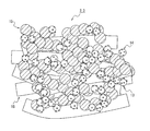
図1に示すように、本発明の実施の形態(以下、本実施形態)に係る固体高分子形燃料電池用の電極触媒層2、3は、触媒13、触媒13を担持する炭素粒子14、高分子電解質15及び繊維状物質16を含む。そして、上記のいずれの構成要素も存在しない部分が空孔となっている。
また、本実施形態に係る電極触媒層2、3は、密度が400mg/cm3以上1000mg/cm3以下の範囲内に設定されており、好ましくは、500mg/cm3以上900mg/cm3以下の範囲内であり、より好ましくは、600mg/cm3以上900mg/cm3以下の範囲内である。繊維状物質16を含むことにより、形成時にクラックが発生せず、また電極触媒層2、3内の空孔を増加させることが可能となる。密度が400mg/cm3より小さいと、電極触媒層2、3が脆く、運転時に空孔が潰れ、排水性が低下することがある。また、密度が1000mg/cm3より大きいと、空孔が少なく、排水性が低下することがある。
図1に示すように、本発明の実施の形態(以下、本実施形態)に係る固体高分子形燃料電池用の電極触媒層2、3は、触媒13、触媒13を担持する炭素粒子14、高分子電解質15及び繊維状物質16を含む。そして、上記のいずれの構成要素も存在しない部分が空孔となっている。
また、本実施形態に係る電極触媒層2、3は、密度が400mg/cm3以上1000mg/cm3以下の範囲内に設定されており、好ましくは、500mg/cm3以上900mg/cm3以下の範囲内であり、より好ましくは、600mg/cm3以上900mg/cm3以下の範囲内である。繊維状物質16を含むことにより、形成時にクラックが発生せず、また電極触媒層2、3内の空孔を増加させることが可能となる。密度が400mg/cm3より小さいと、電極触媒層2、3が脆く、運転時に空孔が潰れ、排水性が低下することがある。また、密度が1000mg/cm3より大きいと、空孔が少なく、排水性が低下することがある。
なお、通常使用される材料のうち最も低密度な材料はポリプロピレンであり、ポリプロピレンを用いて緻密質(無孔質)な層を形成した場合、その密度は900mg/cm3~1000mg/cm3程度となる。これに対し、本実施形態に係る電極触媒層2、3を構成する触媒13、炭素粒子14、高分子電解質15及び繊維状物質16のそれぞれは、ポリプロピレンよりも高密度な材料である。このため、上記材料を用いて、密度が400mg/cm3以上1000mg/cm3以下、より厳密には500mg/cm3以上900mg/cm3以下の条件を満たす緻密質(無孔質)の電極触媒層を製造することは不可能である。つまり、通常使用される材料を用いて緻密質な層を形成した場合には本実施形態に係る電極触媒層2、3の密度を達成し得ないため、本実施形態に係る電極触媒層2、3は空孔を含むものである。
また、電極触媒層2、3は、単層、多層でもよく、密度は均一、不均一、異なっていてもよい。電極触媒層2、3の密度は、高分子電解質膜1側が大きく、その反対側が小さいと、排水性が向上し、より好ましい。
また、繊維状物質16の繊維径と炭素粒子14の粒子径の比(繊維状物質16/炭素粒子14)は、0.01以上10以下の範囲内であることが好ましく、より好ましくは、0.1以上8以下の範囲内である。上記範囲内であれば、電極触媒層2、3内に空孔が形成されやすく、排水性が向上しやすい。繊維状物質16の繊維径及び炭素粒子14の粒子径は、光学顕微鏡、走査電子顕微鏡(SEM)、透過電子顕微鏡(TEM)等により観察し、繊維状物質16の繊維径及び炭素粒子14の粒子径を計測し、その平均値をとることにより算出できる。
また、繊維状物質16の繊維径と炭素粒子14の粒子径の比(繊維状物質16/炭素粒子14)は、0.01以上10以下の範囲内であることが好ましく、より好ましくは、0.1以上8以下の範囲内である。上記範囲内であれば、電極触媒層2、3内に空孔が形成されやすく、排水性が向上しやすい。繊維状物質16の繊維径及び炭素粒子14の粒子径は、光学顕微鏡、走査電子顕微鏡(SEM)、透過電子顕微鏡(TEM)等により観察し、繊維状物質16の繊維径及び炭素粒子14の粒子径を計測し、その平均値をとることにより算出できる。
高分子電解質15としては、イオン伝導性を有するものであればよいが、電極触媒層2、3と高分子電解質膜の密着性を考えると、高分子電解質膜と同質の材料を選択することが好ましい。高分子電解質15には、例えばフッ素系樹脂や炭化水素系樹脂が使用可能できる。例えば、フッ素系樹脂としては、Nafion(デュポン社製、登録商標)、炭化水素系樹脂としては、エンジニアリングプラスチック、又はその共重合体にスルホン酸基を導入したものなどが挙げられる。高分子電解質15の含有量としては、炭素粒子14と繊維状物質16の合算質量に対して10質量%以上200質量%以下の範囲内が好ましい。更に好ましくは、30質量%以上150質量%以下の範囲内である。高分子電解質15の含有量が10質量%より小さいと、プロトン伝導性が低下し、発電性能が低下することがある。また、高分子電解質15の含有量が200質量%より大きいと、フラッディングが起こり、発電性能が低下することがある。
触媒13としては、例えば、白金族元素、金属又はこれらの合金、又は酸化物、複酸化物などが使用できる。白金族元素としては、例えば、白金やパラジウム、ルテニウム、イリジウム、ロジウム、オスミウムがある。金属としては、例えば、鉄、鉛、銅、クロム、コバルト、ニッケル、マンガン、バナジウム、モリブデン、ガリウム、アルミニウムなどが例示できる。その中でも、触媒13としては白金や白金合金が好ましい。また、これらの触媒13の粒径は、大きすぎると触媒13の活性が低下し、小さすぎると触媒13の安定性が低下することがある。そのため、0.5nm以上20nm以下の範囲内が好ましい。更に好ましくは、1nm以上5nm以下の範囲内である。
炭素粒子14としては、微粒子状で導電性を有し、触媒13におかされないものであればどのようなものでも構わない。炭素粒子14の粒径が小さすぎると電子伝導パスが形成されにくくなることがある。一方、炭素粒子14の粒径が大きすぎると電極触媒層2、3が厚くなり抵抗が増加することで、出力特性が低下することがある。そのため炭素粒子14の粒径は、10nm以上1000nm以下の範囲内が好ましい。更に好ましくは、10nm以上100nm以下の範囲内である。
炭素粒子14には、触媒13が担持されていることが好ましい。高表面積の炭素粒子14に触媒13を担持することで、高密度で触媒13が担持でき、触媒活性を向上させることができる。具体的には、炭素粒子14と触媒13との合算質量を100質量%とするとき、触媒13の質量は5質量%以上80質量%以下の範囲内が好ましい。更に好ましくは、10質量%以上60質量%以下の範囲内である。触媒13の質量が80質量%より大きいと、触媒同士の距離が近いため、運転中に触媒同士が凝集・粗大化し、触媒活性が低下しやすい。触媒13の質量が5質量%より小さいと、触媒13を炭素粒子14の表面に均一に担持することができず、触媒13の偏在や凝集・粗大化が起こり、触媒活性が低下しやすい。
繊維状物質16としては、例えば、電子伝導性繊維及びプロトン伝導性繊維が使用できる。繊維状物質16は、以下に示す繊維のうち一種のみを単独で使用してもよいが、二種以上を併用してもよく、電子伝導性繊維とプロトン伝導性繊維を併せて用いてもよい。
本実施形態に係る電子伝導性繊維としては、例えば、カーボンファイバー、カーボンナノチューブ、カーボンナノホーン、導電性高分子ナノファイバーなどが例示できる。特に、導電性や分散性の点でカーボンナノファイバーが好ましい。また、触媒能のある電子伝導性繊維を用いることで、貴金属からなる触媒の使用量を低減できるのでより好ましい。本実施形態に係る固体高分子形燃料電池用触媒層が固体高分子形燃料電池の空気極として用いられる場合には、電子伝導性繊維として、例えば、カーボンナノファイバーから作製したカーボンアロイ触媒が例示できる。また、酸素還元電極用の電極活物質を繊維状に加工したものであってもよく、例えば、Ta、Nb、Ti、Zrから選択される、少なくとも一つの遷移金属元素を含む物質を使用してもよい。これらの遷移金属元素の炭窒化物の部分酸化物、または、これらの遷移金属元素の導電性酸化物や導電性酸窒化物が例示できる。
本実施形態に係る電子伝導性繊維としては、例えば、カーボンファイバー、カーボンナノチューブ、カーボンナノホーン、導電性高分子ナノファイバーなどが例示できる。特に、導電性や分散性の点でカーボンナノファイバーが好ましい。また、触媒能のある電子伝導性繊維を用いることで、貴金属からなる触媒の使用量を低減できるのでより好ましい。本実施形態に係る固体高分子形燃料電池用触媒層が固体高分子形燃料電池の空気極として用いられる場合には、電子伝導性繊維として、例えば、カーボンナノファイバーから作製したカーボンアロイ触媒が例示できる。また、酸素還元電極用の電極活物質を繊維状に加工したものであってもよく、例えば、Ta、Nb、Ti、Zrから選択される、少なくとも一つの遷移金属元素を含む物質を使用してもよい。これらの遷移金属元素の炭窒化物の部分酸化物、または、これらの遷移金属元素の導電性酸化物や導電性酸窒化物が例示できる。
本実施形態に係るプロトン伝導性繊維としては、プロトン伝導性を有する高分子電解質を繊維状に加工したものであればよく、例えば、フッ素系高分子電解質、炭化水素系高分子電解質を用いることができる。フッ素系高分子電解質としては、例えば、デュポン社製Nafion(登録商標)、旭硝子(株)製Flemion(登録商標)、旭化成(株)製Aciplex(登録商標)、ゴア社製Gore Select(登録商標)などを用いることができる。炭化水素系高分子電解質としては、例えば、スルホン化ポリエーテルケトン、スルホン化ポリエーテルスルホン、スルホン化ポリエーテルエーテルスルホン、スルホン化ポリスルフィド、スルホン化ポリフェニレンなどの電解質を用いることができる。中でも、高分子電解質としてデュポン社製Nafion(登録商標)系材料を好適に用いることができる。炭化水素系高分子電解質としては、例えば、スルホン化ポリエーテルケトン、スルホン化ポリエーテルスルホン、スルホン化ポリエーテルエーテルスルホン、スルホン化ポリスルフィド、スルホン化ポリフェニレンなどの電解質を用いることができる。
繊維状物質16の繊維径としては、0.5nm以上500nm以下の範囲が好ましく、10nm以上300nm以下の範囲がより好ましい。上記範囲にすることにより、電極触媒層2、3内の空孔を増加させることができ、高出力化が可能になる。繊維状物質16の繊維径は、光学顕微鏡、走査電子顕微鏡(SEM)、透過電子顕微鏡(TEM)等により観察し、繊維状物質16の繊維径を計測し、その平均値をとることにより算出できる。
また、繊維状物質16の繊維径と炭素粒子14の粒子径の比(繊維状物質16/炭素粒子14)は、0.001以上50以下の範囲内であることが好ましい。上記範囲内であれば、電極触媒層2、3内に空孔が形成されやすく、排水性が向上しやすい。
また、繊維状物質16の繊維径と炭素粒子14の粒子径の比(繊維状物質16/炭素粒子14)は、0.001以上50以下の範囲内であることが好ましい。上記範囲内であれば、電極触媒層2、3内に空孔が形成されやすく、排水性が向上しやすい。
繊維状物質16の繊維長としては1μm以上200μm以下の範囲内が好ましく、1μm以上50μm以下の範囲内がより好ましい。上記範囲にすることにより、電極触媒層2、3の強度を高めることができ、形成時にクラックが生じることを抑制できる。また、電極触媒層2、3内の空孔を増加させることができ、高出力化が可能になる。繊維状物質16の繊維長は、光学顕微鏡、走査電子顕微鏡(SEM)、透過電子顕微鏡(TEM)等により観察し、繊維状物質16の繊維長を計測し、その平均値をとることにより算出できる。
繊維状物質16の含有量は、炭素粒子14の質量に対して10質量%以上250質量%以下の範囲内が好ましく、10質量%以上200質量%以下の範囲内がより好ましい。炭素粒子14の質量に対して10質量%より小さいと、ガス拡散性や排水性が低下することがある。炭素粒子14の質量に対して250質量%より大きいと、触媒13を担持させるための導電体(炭素粒子14及び導電性繊維)の比表面積が減少し、触媒13を高密化できず、触媒活性が低下することがある。
電極触媒層2、3の厚さは、5μm以上30μm以下の範囲内が好ましく、5μm以上20μm以下がより好ましい。電極触媒層2、3の厚さが5μmより小さいと、電極触媒層内2、3において、発電による生成水濃度が高くなり易く、フラッディングが生じ易く、発電性能が低下することがあるため、好ましくない。電極触媒層2、3の厚さが30μmより大きいと、電極触媒層2、3の抵抗が大きくなり、出力が低下することがある。
また、アノード側電極触媒層3とカソード側電極触媒層2の厚さは、同じでもよく、異なっていてもよい。カソード側電極触媒層2の厚さをアノード側電極触媒層3の厚さより厚くすることで、より排水性を高めることができる。カソード側電極触媒層2が厚いと、発電により生成した水を系外に排水しやすい。また、アノードには乾燥した燃料が用いられるため、アノード側電極触媒層3が薄いと、アノード側電極触媒層3が乾燥しやすい。そのため、カソード側の生成水が高分子電解質膜1を通してアノード側に移動する。その結果、カソード側電極触媒層2内の水分量が適度に保たれ、排水性を高めることができる。
また、アノード側電極触媒層3とカソード側電極触媒層2の厚さは、同じでもよく、異なっていてもよい。カソード側電極触媒層2の厚さをアノード側電極触媒層3の厚さより厚くすることで、より排水性を高めることができる。カソード側電極触媒層2が厚いと、発電により生成した水を系外に排水しやすい。また、アノードには乾燥した燃料が用いられるため、アノード側電極触媒層3が薄いと、アノード側電極触媒層3が乾燥しやすい。そのため、カソード側の生成水が高分子電解質膜1を通してアノード側に移動する。その結果、カソード側電極触媒層2内の水分量が適度に保たれ、排水性を高めることができる。
(膜電極接合体)
本実施形態に係る固体高分子形燃料電池用の膜電極接合体12は、例えば図2に示すよう断面図のような構造体となっている。この膜電極接合体12は、高分子電解質膜1と、高分子電解質膜1の一方の面に形成されたカソード側電極触媒層2と、高分子電解質膜1の他方の面に形成されたアノード側電極触媒層3と、を備えた構造となっている。本実施形態に係る電極触媒層は、カソード側電極触媒層2及びアノード側電極触媒層3の一方若しくは両方に該当する。
本実施形態に係る固体高分子形燃料電池用の膜電極接合体12は、例えば図2に示すよう断面図のような構造体となっている。この膜電極接合体12は、高分子電解質膜1と、高分子電解質膜1の一方の面に形成されたカソード側電極触媒層2と、高分子電解質膜1の他方の面に形成されたアノード側電極触媒層3と、を備えた構造となっている。本実施形態に係る電極触媒層は、カソード側電極触媒層2及びアノード側電極触媒層3の一方若しくは両方に該当する。
(固体高分子形燃料電池)
本実施形態に係る固体高分子形燃料電池は、図3に示すように、膜電極接合体12のカソード側電極触媒層2及びアノード側電極触媒層3と対向して、空気極側ガス拡散層4及び燃料極側ガス拡散層5がそれぞれ配置されている。これにより、カソード側電極触媒層2と空気極側ガス拡散層4とから空気極6が構成されると共に、アノード側電極触媒層3と燃料極側ガス拡散層5とで燃料極7が構成される。そして、空気極6及び燃料極7を一組のセパレータ10により挟持することで、単セルの固体高分子形燃料電池11が構成される。一組のセパレータ10は、導電性でかつガス不透過性の材料からなり、空気極側ガス拡散層4又は燃料極側ガス拡散層5に面して配置された反応ガス流通用のガス流路8と、ガス流路8と相対する主面に配置された冷却水流通用の冷却水流路9とを備える。
この固体高分子形燃料電池11は、一方のセパレータ10のガス流路8を通って空気や酸素などの酸化剤が空気極6に供給され、他方のセパレータ10のガス流路8を通って水素を含む燃料ガス若しくは有機物燃料が燃料極7に供給されることによって、発電するようになっている。
本実施形態に係る固体高分子形燃料電池は、図3に示すように、膜電極接合体12のカソード側電極触媒層2及びアノード側電極触媒層3と対向して、空気極側ガス拡散層4及び燃料極側ガス拡散層5がそれぞれ配置されている。これにより、カソード側電極触媒層2と空気極側ガス拡散層4とから空気極6が構成されると共に、アノード側電極触媒層3と燃料極側ガス拡散層5とで燃料極7が構成される。そして、空気極6及び燃料極7を一組のセパレータ10により挟持することで、単セルの固体高分子形燃料電池11が構成される。一組のセパレータ10は、導電性でかつガス不透過性の材料からなり、空気極側ガス拡散層4又は燃料極側ガス拡散層5に面して配置された反応ガス流通用のガス流路8と、ガス流路8と相対する主面に配置された冷却水流通用の冷却水流路9とを備える。
この固体高分子形燃料電池11は、一方のセパレータ10のガス流路8を通って空気や酸素などの酸化剤が空気極6に供給され、他方のセパレータ10のガス流路8を通って水素を含む燃料ガス若しくは有機物燃料が燃料極7に供給されることによって、発電するようになっている。
(電極触媒層の製造方法)
電極触媒層2、3は、触媒層用スラリーを作製し、作製した触媒層用スラリーを基材などに塗工・乾燥することで製造できる。
触媒層用スラリーは、触媒13、炭素粒子14、高分子電解質15、繊維状物質16及び溶媒を含む。溶媒としては、特に限定しないが、高分子電解質15を分散又は溶解できるものがよい。一般的に用いられる溶媒としては、例えば、水、メタノール、エタノール、1-プロパノール、2-プロパノール、1-ブタノール、2-ブタノール、イソブチルアルコール、tert-ブチルアルコールなどのアルコール類、アセトン、メチルエチルケトン、メチルプロピルケトン、メチルブチルケトン、メチルイゾブチルケトン、メチルアミルケトン、ペンタノン、へプタノン、シクロヘキサノン、メチルシクロヘキサノン、アセトニルアセトン、ジエチルケトン、ジプロピルケトン、ジイソブチルケトンなどのケトン類、テトラヒドロフラン、テトラヒドロピラン、ジオキサン、ジエチレングリコールジメチルエーテル、アニソール、メトキシトルエン、ジエチルエーテル、ジプロピルエーテル、ジブチルエーテルなどのエーテル類、イソプロピルアミン、ブチルアミン、イソブチルアミン、シクロヘキシルアミン、ジエチルアミン、アニリンなどのアミン類、蟻酸プロピル、蟻酸イソブチル、蟻酸アミル、酢酸メチル、酢酸エチル、酢酸プロピル、酢酸ブチル、酢酸イソブチル、酢酸ペンチル、酢酸イソペンチル、プロピオン酸メチル、プロピオン酸エチル、プロピオン酸ブチルなどのエステル類、その他酢酸、プロピオン酸、ジメチルホルムアミド、ジメチルアセトアミド、N-メチルピロリドンなどが挙げられる。また、グリコール、グリコールエーテル系溶媒としては、例えば、エチレングリコール、ジエチレングリコール、プロピレングリコール、エチレングリコールモノメチルエーテル、エチレングリコールジメチルエーテル、エチレングリコールジエチルエーテル、ジアセトンアルコール、1-メトキシ-2-プロパノール、1-エトキシ-2-プロパノールなどが挙げられる。
電極触媒層2、3は、触媒層用スラリーを作製し、作製した触媒層用スラリーを基材などに塗工・乾燥することで製造できる。
触媒層用スラリーは、触媒13、炭素粒子14、高分子電解質15、繊維状物質16及び溶媒を含む。溶媒としては、特に限定しないが、高分子電解質15を分散又は溶解できるものがよい。一般的に用いられる溶媒としては、例えば、水、メタノール、エタノール、1-プロパノール、2-プロパノール、1-ブタノール、2-ブタノール、イソブチルアルコール、tert-ブチルアルコールなどのアルコール類、アセトン、メチルエチルケトン、メチルプロピルケトン、メチルブチルケトン、メチルイゾブチルケトン、メチルアミルケトン、ペンタノン、へプタノン、シクロヘキサノン、メチルシクロヘキサノン、アセトニルアセトン、ジエチルケトン、ジプロピルケトン、ジイソブチルケトンなどのケトン類、テトラヒドロフラン、テトラヒドロピラン、ジオキサン、ジエチレングリコールジメチルエーテル、アニソール、メトキシトルエン、ジエチルエーテル、ジプロピルエーテル、ジブチルエーテルなどのエーテル類、イソプロピルアミン、ブチルアミン、イソブチルアミン、シクロヘキシルアミン、ジエチルアミン、アニリンなどのアミン類、蟻酸プロピル、蟻酸イソブチル、蟻酸アミル、酢酸メチル、酢酸エチル、酢酸プロピル、酢酸ブチル、酢酸イソブチル、酢酸ペンチル、酢酸イソペンチル、プロピオン酸メチル、プロピオン酸エチル、プロピオン酸ブチルなどのエステル類、その他酢酸、プロピオン酸、ジメチルホルムアミド、ジメチルアセトアミド、N-メチルピロリドンなどが挙げられる。また、グリコール、グリコールエーテル系溶媒としては、例えば、エチレングリコール、ジエチレングリコール、プロピレングリコール、エチレングリコールモノメチルエーテル、エチレングリコールジメチルエーテル、エチレングリコールジエチルエーテル、ジアセトンアルコール、1-メトキシ-2-プロパノール、1-エトキシ-2-プロパノールなどが挙げられる。
触媒層用スラリーの塗工方法としては、例えば、ドクターブレード法、ダイコーティング法、ディッピング法、スクリーン印刷法、ラミネータロールコーティング法、スプレー法などが挙げられるが、特に限定しない。
触媒層用スラリーの乾燥方法としては、例えば、温風乾燥、IR乾燥などが挙げられる。乾燥温度は、40℃以上200℃以下の範囲内、好ましくは40℃以上120℃以下の範囲内である。乾燥時間は、0.5分以上1時間以下の範囲内、好ましくは1以上30分以下の範囲内である。
ここで、電極触媒層2、3は、密度が400mg/cm3以上1000mg/cm3以下の範囲内に設定するには、繊維状物質16の添加量や繊維長、乾燥のための加熱温度、温度勾配、電極触媒層が乾燥されるまでに付与される膜厚方向の加圧などの条件を調整することで実現することが可能である。
触媒層用スラリーの乾燥方法としては、例えば、温風乾燥、IR乾燥などが挙げられる。乾燥温度は、40℃以上200℃以下の範囲内、好ましくは40℃以上120℃以下の範囲内である。乾燥時間は、0.5分以上1時間以下の範囲内、好ましくは1以上30分以下の範囲内である。
ここで、電極触媒層2、3は、密度が400mg/cm3以上1000mg/cm3以下の範囲内に設定するには、繊維状物質16の添加量や繊維長、乾燥のための加熱温度、温度勾配、電極触媒層が乾燥されるまでに付与される膜厚方向の加圧などの条件を調整することで実現することが可能である。
(膜電極接合体の製造方法)
膜電極接合体12の製造方法としては、例えば、転写基材又はガス拡散層4、5に電極触媒層2、3を形成した後、高分子電解質膜1に熱圧着で電極触媒層2、3を形成する方法や高分子電解質膜1に直接電極触媒層2、3を形成する方法が挙げられる。高分子電解質膜1に直接電極触媒層2、3を形成する方法は、高分子電解質膜1と電極触媒層2、3との密着性が高く、電極触媒層2、3が潰れる恐れが低いため、好ましい。
膜電極接合体12の製造方法としては、例えば、転写基材又はガス拡散層4、5に電極触媒層2、3を形成した後、高分子電解質膜1に熱圧着で電極触媒層2、3を形成する方法や高分子電解質膜1に直接電極触媒層2、3を形成する方法が挙げられる。高分子電解質膜1に直接電極触媒層2、3を形成する方法は、高分子電解質膜1と電極触媒層2、3との密着性が高く、電極触媒層2、3が潰れる恐れが低いため、好ましい。
以上説明したように、本実施形態に係る電極触媒層2、3は、触媒13、炭素粒子14、高分子電解質15及び繊維状物質16を含み、密度が400mg/cm3以上1000mg/cm3以下の範囲内、好ましくは密度が500mg/cm3以上900mg/cm3以下の範囲内である。また、高分子電解質15の質量を炭素粒子14と繊維状物質16の合算質量に対して20質量%以上200質量%以下の範囲内としてもよい。
この構成によれば、排水性やガス拡散性が向上でき、高出力が可能な固体高分子形燃料電池用の電極触媒層を提供することができる。
そして、本実施形態に係る電極触媒層2、3は、例えば、固体高分子形燃料電池に適用することが極めて好適である。
この構成によれば、排水性やガス拡散性が向上でき、高出力が可能な固体高分子形燃料電池用の電極触媒層を提供することができる。
そして、本実施形態に係る電極触媒層2、3は、例えば、固体高分子形燃料電池に適用することが極めて好適である。
なお、本実施形態では触媒13を炭素粒子14に担持させた場合について説明したが、触媒13を繊維状物質16に担持させてもよく、さらに炭素粒子14及び繊維状物質16のいずれにも担持させてもよい。繊維状物質16で形成された空隙は発電による生成水の排出経路とすることができる。ここで、繊維状物質16に触媒13を担持させた場合は、生成水の排出経路内で電極反応も起こる。一方で、触媒13を炭素粒子14に担持させることで、炭素粒子14と触媒13とガスとに起因する三相界面による反応点と、繊維状物質16により形成された空間による生成水の排出経路とを区別でき、触媒電極層の排水性を向上することができるため好ましい。
次に、本発明に基づく実施例について説明する。
[密度の算出]
密度は、電極触媒層2、3の質量と厚さから求めた。電極触媒層2、3の質量は、触媒層用スラリー塗工量から求めた質量又は乾燥質量を用いた。電極触媒層2、3の質量を塗工量から求める場合は、予め触媒層用スラリーの固形分(質量%)を求めておき、所定の塗工量と固形分質量から求めた。また、電極触媒層2、3の質量を乾燥質量から求める場合は、電極触媒層2、3を所定の大きさに加工し、その質量を計量し求めた。電極触媒層2、3の厚さは、走査電子顕微鏡(倍率:2000倍)で断面を観察し、電極触媒層2、3の厚さを計測し、その平均値求めた。
[密度の算出]
密度は、電極触媒層2、3の質量と厚さから求めた。電極触媒層2、3の質量は、触媒層用スラリー塗工量から求めた質量又は乾燥質量を用いた。電極触媒層2、3の質量を塗工量から求める場合は、予め触媒層用スラリーの固形分(質量%)を求めておき、所定の塗工量と固形分質量から求めた。また、電極触媒層2、3の質量を乾燥質量から求める場合は、電極触媒層2、3を所定の大きさに加工し、その質量を計量し求めた。電極触媒層2、3の厚さは、走査電子顕微鏡(倍率:2000倍)で断面を観察し、電極触媒層2、3の厚さを計測し、その平均値求めた。
[発電特性の評価]
電極触媒層2、3の外側にガス拡散層(SIGRACET(登録商標) 35BC、SGL社製)を配置して、市販のJARI標準セルを用いて発電特性の評価を行った。セル温度は、80℃として、アノードに水素(100%RH)、カソードに空気(100%RH)を供給した。
電極触媒層2、3の外側にガス拡散層(SIGRACET(登録商標) 35BC、SGL社製)を配置して、市販のJARI標準セルを用いて発電特性の評価を行った。セル温度は、80℃として、アノードに水素(100%RH)、カソードに空気(100%RH)を供給した。
[繊維状物質の繊維径および炭素粒子の粒子径の算出]
繊維状物質16の繊維径および炭素粒子14の粒子径の算出は、走査電子顕微鏡(倍率:30000倍)で断面を観察し、繊維状物質16の繊維径および炭素粒子14の粒子径を計測し、その平均値(10箇所)を求めた。
繊維状物質16の繊維径および炭素粒子14の粒子径の算出は、走査電子顕微鏡(倍率:30000倍)で断面を観察し、繊維状物質16の繊維径および炭素粒子14の粒子径を計測し、その平均値(10箇所)を求めた。
<第1実施例>
[実施例1-1]
電極触媒層の厚さおよび密度が表2に記載の値になるように電極触媒層を形成した。
まず、白金担持カーボン(TEC10E50E、田中貴金属社製)20gを容器にとり、水を加えて混合後、1-プロパノール、電解質(Nafion(登録商標)分散液、和光純薬工業)と繊維状物質としてカーボンナノファイバー(昭和電工社製、商品名「VGCF」、繊維径約150nm、繊維長約10μm)10gを加えて撹拌して、触媒層用スラリーを得た。
得られた触媒層用スラリーを高分子電解質膜(デュポン社製、Nafion212)にダイコーティング法で塗工し、80℃の炉内で乾燥することで実施例1-1の電極触媒層を有した膜電極接合体を得た。
[実施例1-1]
電極触媒層の厚さおよび密度が表2に記載の値になるように電極触媒層を形成した。
まず、白金担持カーボン(TEC10E50E、田中貴金属社製)20gを容器にとり、水を加えて混合後、1-プロパノール、電解質(Nafion(登録商標)分散液、和光純薬工業)と繊維状物質としてカーボンナノファイバー(昭和電工社製、商品名「VGCF」、繊維径約150nm、繊維長約10μm)10gを加えて撹拌して、触媒層用スラリーを得た。
得られた触媒層用スラリーを高分子電解質膜(デュポン社製、Nafion212)にダイコーティング法で塗工し、80℃の炉内で乾燥することで実施例1-1の電極触媒層を有した膜電極接合体を得た。
[実施例1-2]
繊維状物質としてカーボンナノチューブ(繊維径約1nm、繊維長約1μm)を用いた以外は、実施例1-1と同様の手順で実施例1-2の電極触媒層を有した膜電極接合体を得た。
[実施例1-3]
乾燥温度を高くした以外は、実施例1-1と同様の手順で実施例1-3の電極触媒層を有した膜電極接合体を得た。
[実施例1-4]
繊維状物質の量を増加させた以外は、実施例1-1と同様の手順で実施例1-4の電極触媒層を有した膜電極接合体を得た。
繊維状物質としてカーボンナノチューブ(繊維径約1nm、繊維長約1μm)を用いた以外は、実施例1-1と同様の手順で実施例1-2の電極触媒層を有した膜電極接合体を得た。
[実施例1-3]
乾燥温度を高くした以外は、実施例1-1と同様の手順で実施例1-3の電極触媒層を有した膜電極接合体を得た。
[実施例1-4]
繊維状物質の量を増加させた以外は、実施例1-1と同様の手順で実施例1-4の電極触媒層を有した膜電極接合体を得た。
[比較例1-1]
PET基材に塗工し、熱圧着により電解質膜に転写した以外は、実施例1-1と同様の手順で比較例1-1の電極触媒層を有した膜電極接合体を得た。
[比較例1-2]
繊維状物質を加えないこと以外は、実施例1-1と同様の手順で比較例1-2の電極触媒層を有した膜電極接合体を得た。
[比較例1-3]
繊維状物質を加えず、またPET基材に塗工し、熱圧着により電解質膜に転写した以外は、実施例1-1と同様の手順で比較例1-3の電極触媒層を有した膜電極接合体を得た。
PET基材に塗工し、熱圧着により電解質膜に転写した以外は、実施例1-1と同様の手順で比較例1-1の電極触媒層を有した膜電極接合体を得た。
[比較例1-2]
繊維状物質を加えないこと以外は、実施例1-1と同様の手順で比較例1-2の電極触媒層を有した膜電極接合体を得た。
[比較例1-3]
繊維状物質を加えず、またPET基材に塗工し、熱圧着により電解質膜に転写した以外は、実施例1-1と同様の手順で比較例1-3の電極触媒層を有した膜電極接合体を得た。
実施例1-1~1-4、比較例1-1~1-3の触媒層について、顕微鏡(倍率:200倍)で観察して10μm以上クラックの有無について評価した。その評価結果を表1に示す。

表1に示す通り、繊維状物質を加えない場合(比較例1-2)は、PETフィルムにクラックなしで塗工できたが、高分子電解質膜でクラックが多く発生した。これに対して、実施例1-1~1-4及び比較例1-1のように繊維状物質を加えた場合は、クラックがない電極触媒層であった。
また実施例1-1~1-4、比較例1-1~1-3の電極触媒層について、電極触媒層の密度及び発電特性を評価した。その評価結果を表2に示す。
ここで、各電極触媒層において、配合する触媒の質量が同じになるように調整しているが、他の構成が異なるため、各電極触媒層の厚さが異なっている。
また実施例1-1~1-4、比較例1-1~1-3の電極触媒層について、電極触媒層の密度及び発電特性を評価した。その評価結果を表2に示す。
ここで、各電極触媒層において、配合する触媒の質量が同じになるように調整しているが、他の構成が異なるため、各電極触媒層の厚さが異なっている。
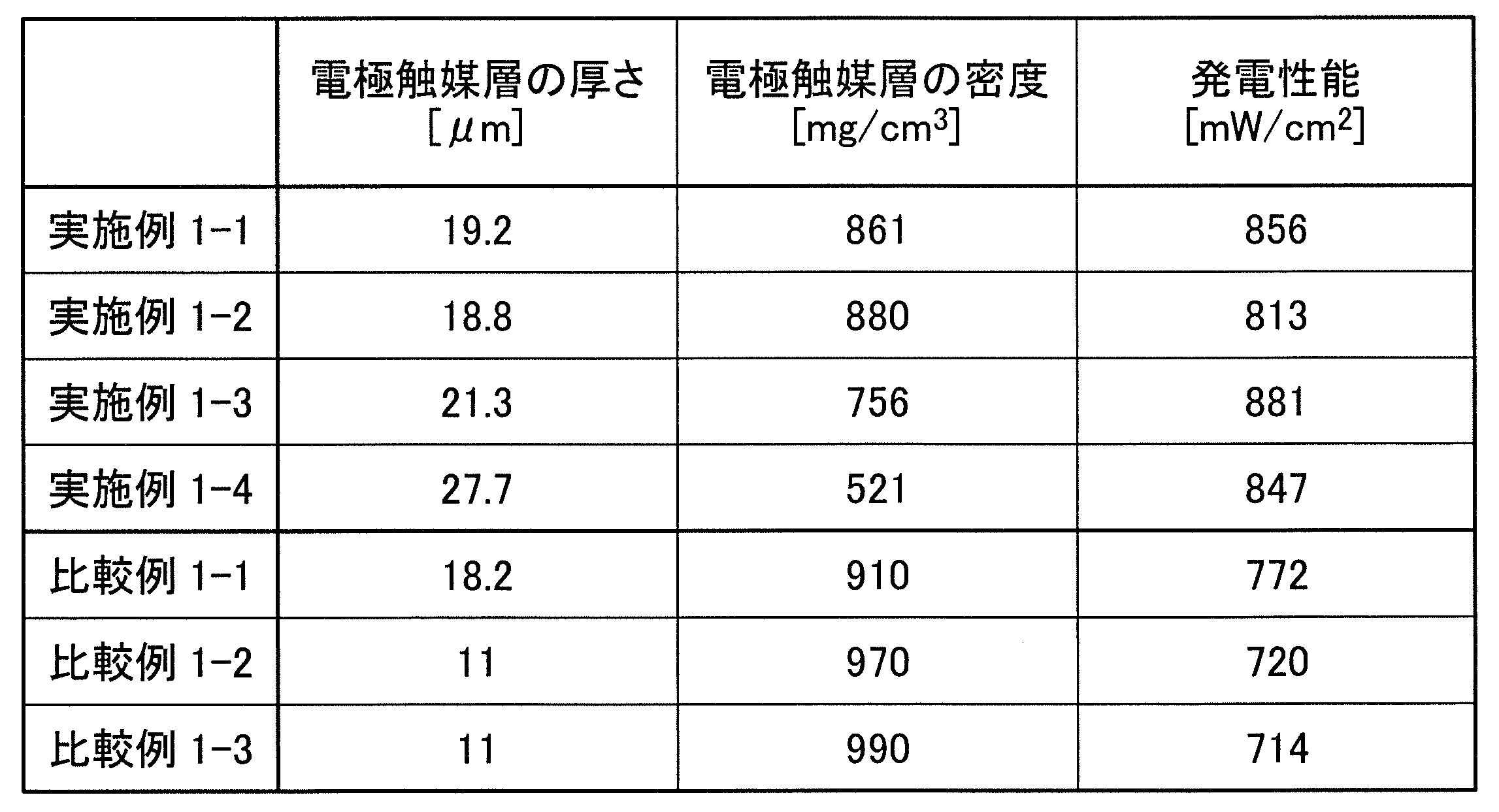
表1及び表2から、繊維状物質を加えないと本発明の密度よりも密度が高くてもクラックが発生しやすくなることが分かる。
以上より、本実施形態によれば、触媒13、炭素粒子14、高分子電解質15及び繊維状物質16からなり、密度が500mg/cm3以上900mg/cm3以下の範囲内である電極触媒層2、3を使用することで、クラックが発生せず、排水性やガス拡散性が向上して、高出力が可能な固体高分子形燃料電池用の電極触媒層を提供することができることが分かった。
以上より、本実施形態によれば、触媒13、炭素粒子14、高分子電解質15及び繊維状物質16からなり、密度が500mg/cm3以上900mg/cm3以下の範囲内である電極触媒層2、3を使用することで、クラックが発生せず、排水性やガス拡散性が向上して、高出力が可能な固体高分子形燃料電池用の電極触媒層を提供することができることが分かった。
なお、密度が400mg/cm3以上であれば、密度が500mg/cm3以上900mg/cm3以下の場合と比較して、発電性能は低下するものの、従来技術と比較すると、発電性能は向上しており、使用上問題はない。
また、密度が1000mg/cm3以下であれば、密度が500mg/cm3以上900mg/cm3以下の場合と比較して、発電性能は低下するものの、従来技術と比較すると、発電性能は向上しており、使用上問題はない。
また、密度が1000mg/cm3以下であれば、密度が500mg/cm3以上900mg/cm3以下の場合と比較して、発電性能は低下するものの、従来技術と比較すると、発電性能は向上しており、使用上問題はない。
<第2実施例>
[実施例2-1]
電極触媒層の厚さおよび密度が表3に記載の値になるように電極触媒層を形成した。
まず、白金担持カーボン(TEC10E50E、田中貴金属社製)を容器にとり、水を加えて混合後、1-プロパノール、電解質(Nafion(登録商標)分散液、和光純薬工業)と繊維状物質としてカーボンナノファイバー(昭和電工社製、商品名「VGCF」、繊維径約150nm、繊維長約10μm)を加えて撹拌して、触媒層用スラリーを得た。なお、高分子電解質の質量は炭素粒子と繊維状物質の合算質量に対して75質量%、繊維状物質の質量は炭素粒子の質量に対して100質量%となるように加えた。
得られた触媒層用スラリーを高分子電解質膜(デュポン社製、Nafion212)にダイコーティング法で塗工し、80℃の炉内で乾燥することで実施例2-1の電極触媒層を有した膜電極接合体を得た。
[実施例2-1]
電極触媒層の厚さおよび密度が表3に記載の値になるように電極触媒層を形成した。
まず、白金担持カーボン(TEC10E50E、田中貴金属社製)を容器にとり、水を加えて混合後、1-プロパノール、電解質(Nafion(登録商標)分散液、和光純薬工業)と繊維状物質としてカーボンナノファイバー(昭和電工社製、商品名「VGCF」、繊維径約150nm、繊維長約10μm)を加えて撹拌して、触媒層用スラリーを得た。なお、高分子電解質の質量は炭素粒子と繊維状物質の合算質量に対して75質量%、繊維状物質の質量は炭素粒子の質量に対して100質量%となるように加えた。
得られた触媒層用スラリーを高分子電解質膜(デュポン社製、Nafion212)にダイコーティング法で塗工し、80℃の炉内で乾燥することで実施例2-1の電極触媒層を有した膜電極接合体を得た。
[実施例2-2]
高分子電解質の質量を炭素粒子と繊維状物質の合算質量に対して100質量%となるように加えた以外は、実施例2-1と同様の手順で実施例2-2の電極触媒層を有した膜電極接合体を得た。
[実施例2-3]
高分子電解質の質量を炭素粒子と繊維状物質の合算質量に対して15質量%となるように加えた以外は、実施例2-1と同様の手順で実施例2-3の電極触媒層を有した膜電極接合体を得た。
[実施例2-4]
繊維状物質としてカーボンナノチューブ(繊維径約1nm、繊維長約1μm)を用いた以外は、実施例2-1と同様の手順で実施例2-4の電極触媒層を有した膜電極接合体を得た。
高分子電解質の質量を炭素粒子と繊維状物質の合算質量に対して100質量%となるように加えた以外は、実施例2-1と同様の手順で実施例2-2の電極触媒層を有した膜電極接合体を得た。
[実施例2-3]
高分子電解質の質量を炭素粒子と繊維状物質の合算質量に対して15質量%となるように加えた以外は、実施例2-1と同様の手順で実施例2-3の電極触媒層を有した膜電極接合体を得た。
[実施例2-4]
繊維状物質としてカーボンナノチューブ(繊維径約1nm、繊維長約1μm)を用いた以外は、実施例2-1と同様の手順で実施例2-4の電極触媒層を有した膜電極接合体を得た。
[実施例2-5]
高分子電解質の質量を炭素粒子と繊維状物質の合算質量に対して42質量%、繊維状物質の質量を炭素粒子の質量に対して260質量%となるように加えた以外は、実施例2-1と同様の手順で実施例2-5の電極触媒層を有した膜電極接合体を得た。
[実施例2-6]
高分子電解質の質量を炭素粒子と繊維状物質の合算質量に対して54質量%、繊維状物質の質量を炭素粒子の質量に対して180質量%となるように加えた以外は、実施例2-1と同様の手順で実施例2-6の電極触媒層を有した膜電極接合体を得た。
[実施例2-7]
高分子電解質の質量を炭素粒子と繊維状物質の合算質量に対して100質量%、繊維状物質の質量を炭素粒子の質量に対して50質量%となるように加えた以外は、実施例2-1と同様の手順で実施例2-7の電極触媒層を有した膜電極接合体を得た。
高分子電解質の質量を炭素粒子と繊維状物質の合算質量に対して42質量%、繊維状物質の質量を炭素粒子の質量に対して260質量%となるように加えた以外は、実施例2-1と同様の手順で実施例2-5の電極触媒層を有した膜電極接合体を得た。
[実施例2-6]
高分子電解質の質量を炭素粒子と繊維状物質の合算質量に対して54質量%、繊維状物質の質量を炭素粒子の質量に対して180質量%となるように加えた以外は、実施例2-1と同様の手順で実施例2-6の電極触媒層を有した膜電極接合体を得た。
[実施例2-7]
高分子電解質の質量を炭素粒子と繊維状物質の合算質量に対して100質量%、繊維状物質の質量を炭素粒子の質量に対して50質量%となるように加えた以外は、実施例2-1と同様の手順で実施例2-7の電極触媒層を有した膜電極接合体を得た。
[実施例2-8]
高分子電解質の質量を炭素粒子と繊維状物質の合算質量に対して130質量%、繊維状物質の質量を炭素粒子の質量に対して15質量%となるように加えた以外は、実施例2-1と同様の手順で実施例2-8の電極触媒層を有した膜電極接合体を得た。
[実施例2-9]
高分子電解質の質量を炭素粒子と繊維状物質の合算質量に対して139質量%、繊維状物質の質量を炭素粒子の質量に対して8質量%となるように加えた以外は、実施例2-1と同様の手順で実施例2-9の電極触媒層を有した膜電極接合体を得た。
高分子電解質の質量を炭素粒子と繊維状物質の合算質量に対して130質量%、繊維状物質の質量を炭素粒子の質量に対して15質量%となるように加えた以外は、実施例2-1と同様の手順で実施例2-8の電極触媒層を有した膜電極接合体を得た。
[実施例2-9]
高分子電解質の質量を炭素粒子と繊維状物質の合算質量に対して139質量%、繊維状物質の質量を炭素粒子の質量に対して8質量%となるように加えた以外は、実施例2-1と同様の手順で実施例2-9の電極触媒層を有した膜電極接合体を得た。
[実施例2-10]
白金担持カーボンとしてTEC10E70TPM(田中貴金属社製)を用いた以外は、実施例2-1と同様の手順で実施例2-10の電極触媒層を有した膜電極接合体を得た。
[実施例2-11]
白金担持カーボンとしてTEC10E60TPM(田中貴金属社製)を用いた以外は、実施例2-1と同様の手順で実施例2-11の電極触媒層を有した膜電極接合体を得た。
[実施例2-12]
白金担持カーボンとしてTEC10E40E(田中貴金属社製)を用いた以外は、実施例2-1と同様の手順で実施例2-12の電極触媒層を有した膜電極接合体を得た。
白金担持カーボンとしてTEC10E70TPM(田中貴金属社製)を用いた以外は、実施例2-1と同様の手順で実施例2-10の電極触媒層を有した膜電極接合体を得た。
[実施例2-11]
白金担持カーボンとしてTEC10E60TPM(田中貴金属社製)を用いた以外は、実施例2-1と同様の手順で実施例2-11の電極触媒層を有した膜電極接合体を得た。
[実施例2-12]
白金担持カーボンとしてTEC10E40E(田中貴金属社製)を用いた以外は、実施例2-1と同様の手順で実施例2-12の電極触媒層を有した膜電極接合体を得た。
[実施例2-13]
触媒層用スラリーを100℃で乾燥した以外は、実施例2-10と同様の手順で実施例2-13の電極触媒層を有した膜電極接合体を得た。
[実施例2-14]
触媒層用スラリーを100℃で乾燥した以外は、実施例2-11と同様の手順で実施例2-14の電極触媒層を有した膜電極接合体を得た。
[実施例2-15]
PET基材に塗工し、熱圧着により電解質膜に転写した以外は、実施例2-1と同様の手順で実施例2-15の電極触媒層を有した膜電極接合体を得た。
触媒層用スラリーを100℃で乾燥した以外は、実施例2-10と同様の手順で実施例2-13の電極触媒層を有した膜電極接合体を得た。
[実施例2-14]
触媒層用スラリーを100℃で乾燥した以外は、実施例2-11と同様の手順で実施例2-14の電極触媒層を有した膜電極接合体を得た。
[実施例2-15]
PET基材に塗工し、熱圧着により電解質膜に転写した以外は、実施例2-1と同様の手順で実施例2-15の電極触媒層を有した膜電極接合体を得た。
[実施例2-16]
PET基材に塗工し、熱圧着により電解質膜に転写した以外は、実施例2-2と同様の手順で実施例2-16の電極触媒層を有した膜電極接合体を得た。
[実施例2-17]
白金担持カーボンとしてTEC10E70TPM(田中貴金属社製)を用いて、電極触媒層の厚さが5μm以下となるように塗工量を調整した以外は、実施例2-8と同様の手順で実施例2-17の電極触媒層を有した膜電極接合体を得た。
PET基材に塗工し、熱圧着により電解質膜に転写した以外は、実施例2-2と同様の手順で実施例2-16の電極触媒層を有した膜電極接合体を得た。
[実施例2-17]
白金担持カーボンとしてTEC10E70TPM(田中貴金属社製)を用いて、電極触媒層の厚さが5μm以下となるように塗工量を調整した以外は、実施例2-8と同様の手順で実施例2-17の電極触媒層を有した膜電極接合体を得た。
[実施例2-18]
塗工量を半分にした以外は、実施例2-1と同様の手順で実施例2-18の電極触媒層を有した膜電極接合体を得た。
[実施例2-19]
白金担持カーボンとして、炭素粒子(粒子径約120nm)を用いた以外は、実施例2-4と同様の手順で実施例2-19の電極触媒層を有した膜電極接合体を得た。
[実施例2-20]
高分子電解質の質量を炭素粒子と繊維状物質の合算質量に対して7質量%、繊維状物質の質量を炭素粒子の質量に対して180質量%となるように加えた以外は、実施例2-1と同様の手順で実施例2-20の電極触媒層を有した膜電極接合体を得た。
塗工量を半分にした以外は、実施例2-1と同様の手順で実施例2-18の電極触媒層を有した膜電極接合体を得た。
[実施例2-19]
白金担持カーボンとして、炭素粒子(粒子径約120nm)を用いた以外は、実施例2-4と同様の手順で実施例2-19の電極触媒層を有した膜電極接合体を得た。
[実施例2-20]
高分子電解質の質量を炭素粒子と繊維状物質の合算質量に対して7質量%、繊維状物質の質量を炭素粒子の質量に対して180質量%となるように加えた以外は、実施例2-1と同様の手順で実施例2-20の電極触媒層を有した膜電極接合体を得た。
[比較例2-1]
熱圧着する圧力を2倍にした以外は、実施例2-15と同様の手順で比較例2-1の電極触媒層を有した膜電極接合体を得た。
[比較例2-2]
高分子電解質の質量を炭素粒子と繊維状物質の合算質量に対して204質量%、繊維状物質の質量を炭素粒子の質量に対して8質量%となるように加えた以外は、実施例2-1と同様の手順で比較例2-2の電極触媒層を有した膜電極接合体を得た。
[比較例2-3]
高分子電解質の質量を炭素粒子と繊維状物質の合算質量に対して150質量%、繊維状物質の質量を炭素粒子の質量に対して0質量%となるように加えた以外は、実施例2-1と同様の手順で比較例2-3の電極触媒層を有した膜電極接合体を得た。なお、触媒層にはクラックが発生した。
熱圧着する圧力を2倍にした以外は、実施例2-15と同様の手順で比較例2-1の電極触媒層を有した膜電極接合体を得た。
[比較例2-2]
高分子電解質の質量を炭素粒子と繊維状物質の合算質量に対して204質量%、繊維状物質の質量を炭素粒子の質量に対して8質量%となるように加えた以外は、実施例2-1と同様の手順で比較例2-2の電極触媒層を有した膜電極接合体を得た。
[比較例2-3]
高分子電解質の質量を炭素粒子と繊維状物質の合算質量に対して150質量%、繊維状物質の質量を炭素粒子の質量に対して0質量%となるように加えた以外は、実施例2-1と同様の手順で比較例2-3の電極触媒層を有した膜電極接合体を得た。なお、触媒層にはクラックが発生した。
[比較結果]
実施例2-1~2-20の膜電極接合体及び比較例2-1~2-3の膜電極接合体を備えた固体高分子形燃料電池の、電極触媒層の組成、電極触媒層の厚さ、電極触媒層の密度、発電性能を表3に示す。
発電性能については、電流密度が1.0A/cm2のときの電圧が0.55V以上である場合を「△」、0.58V以上である場合を「○」、0.61V以上である場合を「◎」、0.55V未満である場合を「×」とした。発電性能は高出力であるほど好ましいが、0.55V以上あることで使用上問題ない膜電極接合体を得られたと判断した。
実施例2-1~2-20の膜電極接合体及び比較例2-1~2-3の膜電極接合体を備えた固体高分子形燃料電池の、電極触媒層の組成、電極触媒層の厚さ、電極触媒層の密度、発電性能を表3に示す。
発電性能については、電流密度が1.0A/cm2のときの電圧が0.55V以上である場合を「△」、0.58V以上である場合を「○」、0.61V以上である場合を「◎」、0.55V未満である場合を「×」とした。発電性能は高出力であるほど好ましいが、0.55V以上あることで使用上問題ない膜電極接合体を得られたと判断した。
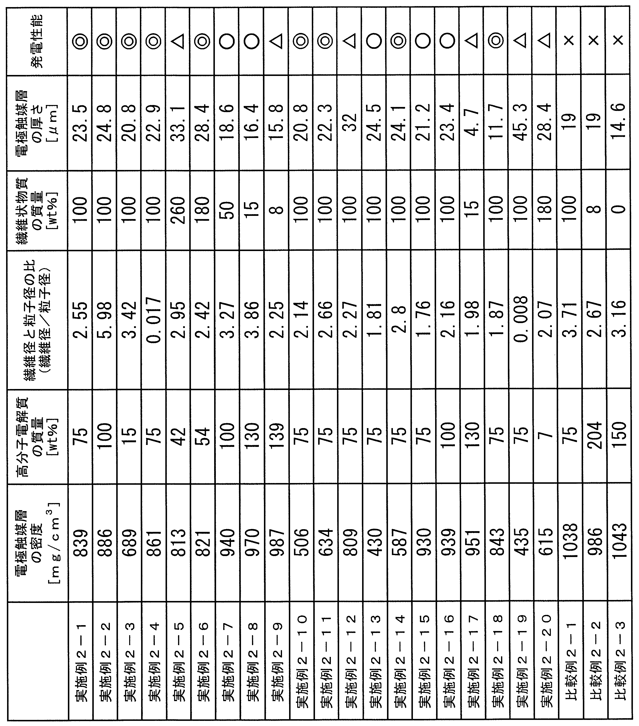
表3の結果より、本実施形態によれば、触媒13、炭素粒子14、高分子電解質15及び繊維状物質16を有し、密度が500mg/cm3以上900mg/cm3以下の範囲内である電極触媒層2、3を使用することで、或いは密度が400mg/cm3以上1000mg/cm3以下の範囲内であり、高分子電解質15の質量が炭素粒子14と繊維状物質16の合算質量に対して10質量%以上200質量%以下の範囲内である電極触媒層2、3を使用することで、発電性能に優れた固体高分子形燃料電池用の膜電極接合体12を提供できる。
1 高分子電解質膜
2 カソード側電極触媒層
3 アノード側電極触媒層
4 空気極側ガス拡散層
5 燃料極側ガス拡散層
6 空気極
7 燃料極
8 ガス流路
9 冷却水流路
10 セパレータ
11 固体高分子形燃料電池
12 膜電極接合体
13 触媒
14 炭素粒子
15 高分子電解質
16 繊維状物質
2 カソード側電極触媒層
3 アノード側電極触媒層
4 空気極側ガス拡散層
5 燃料極側ガス拡散層
6 空気極
7 燃料極
8 ガス流路
9 冷却水流路
10 セパレータ
11 固体高分子形燃料電池
12 膜電極接合体
13 触媒
14 炭素粒子
15 高分子電解質
16 繊維状物質
Claims (12)
- 高分子電解質膜に接合される電極触媒層であって、
触媒、炭素粒子、高分子電解質及び繊維状物質を有し、
密度が500mg/cm3以上900mg/cm3以下の範囲内であることを特徴とする電極触媒層。 - 高分子電解質膜に接合される電極触媒層であって、
触媒、炭素粒子、高分子電解質及び繊維状物質を有し、
密度が400mg/cm3以上1000mg/cm3以下の範囲内であり、
前記高分子電解質の質量が前記炭素粒子と前記繊維状物質の合算質量に対して10質量%以上200質量%以下の範囲内であることを特徴とする電極触媒層。 - 前記繊維状物質の繊維径と前記炭素粒子の粒子径との比(繊維状物質/炭素粒子)が0.01以上10以下の範囲内であることを特徴とする請求項2に記載の電極触媒層。
- 前記繊維状物質の質量が前記炭素粒子の質量に対して10質量%以上250質量%以下の範囲内であることを特徴とする請求項2又は請求項3に記載の電極触媒層。
- 前記繊維状物質の平均繊維径が0.5nm以上500nm以下の範囲内であることを特徴とする請求項2から請求項4のいずれか1項に記載の電極触媒層。
- 前記繊維状物質の平均繊維長が1μm以上200μm以下の範囲内であることを特徴とする請求項2から請求項5のいずれか1項に記載の電極触媒層。
- 前記密度が500mg/cm3以上900mg/cm3以下の範囲内であることを特徴とする請求項2から請求項6のいずれか1項に記載の電極触媒層。
- 前記炭素粒子が前記触媒を担持して触媒担持粒子となっていることを特徴とする請求項1から請求項7のいずれか1項に記載の電極触媒層。
- 前記繊維状物質は、カーボンナノチューブ又はカーボンナノファイバーであることを特徴とする請求項1から請求項8のいずれか1項に記載の電極触媒層。
- 前記電極触媒層の厚さが5μm以上30μm以下の範囲内であることを特徴とする請求項1から請求項9のいずれか1項に記載の電極触媒層。
- 前記電極触媒層は、カソード側に配置されるカソード側電極触媒層及びアノード側に配置されるアノード側電極触媒層の少なくとも一方であり、
前記カソード側電極触媒層の厚さが、前記アノード側電極触媒層の厚さより厚いことを特徴とする請求項1から請求項10のいずれか1項に記載の電極触媒層。 - 請求項1から請求項11のいずれか1項に記載の電極触媒層を備えたことを特徴とする固体高分子形燃料電池。
Priority Applications (3)
| Application Number | Priority Date | Filing Date | Title |
|---|---|---|---|
| EP18873347.1A EP3534445B1 (en) | 2017-10-31 | 2018-10-30 | Electrode catalyst layer and solid polymer fuel cell |
| US16/465,115 US11545674B2 (en) | 2017-10-31 | 2018-10-30 | Electrode catalyst layer and polymer electrolyte fuel cell |
| CN201880068587.6A CN111247677B (zh) | 2017-10-31 | 2018-10-30 | 电极催化剂层及固体高分子型燃料电池 |
Applications Claiming Priority (4)
| Application Number | Priority Date | Filing Date | Title |
|---|---|---|---|
| JP2017211041A JP6332541B1 (ja) | 2017-10-31 | 2017-10-31 | 電極触媒層 |
| JP2017-211041 | 2017-10-31 | ||
| JP2018102420 | 2018-05-29 | ||
| JP2018-102420 | 2018-05-29 |
Publications (1)
| Publication Number | Publication Date |
|---|---|
| WO2019088096A1 true WO2019088096A1 (ja) | 2019-05-09 |
Family
ID=66333102
Family Applications (1)
| Application Number | Title | Priority Date | Filing Date |
|---|---|---|---|
| PCT/JP2018/040320 Ceased WO2019088096A1 (ja) | 2017-10-31 | 2018-10-30 | 電極触媒層及び固体高分子形燃料電池 |
Country Status (4)
| Country | Link |
|---|---|
| US (1) | US11545674B2 (ja) |
| EP (1) | EP3534445B1 (ja) |
| CN (1) | CN111247677B (ja) |
| WO (1) | WO2019088096A1 (ja) |
Families Citing this family (3)
| Publication number | Priority date | Publication date | Assignee | Title |
|---|---|---|---|---|
| EP4184619A4 (en) * | 2020-07-15 | 2025-04-09 | Toppan Inc. | Electrode catalyst layer, membrane electrode assembly, and solid polymer fuel cell |
| JP2022052390A (ja) * | 2020-09-23 | 2022-04-04 | 凸版印刷株式会社 | 電極触媒層、及び膜電極接合体 |
| CN112615018A (zh) * | 2020-12-21 | 2021-04-06 | 上海电气集团股份有限公司 | 阴极催化层及其制备方法、膜电极和燃料电池 |
Citations (5)
| Publication number | Priority date | Publication date | Assignee | Title |
|---|---|---|---|---|
| JPS5537178B2 (ja) | 1975-10-20 | 1980-09-26 | ||
| JPH10241703A (ja) | 1997-02-21 | 1998-09-11 | Toyota Motor Corp | 燃料電池用の電極および発電層並びにその製造方法 |
| JP2006278232A (ja) * | 2005-03-30 | 2006-10-12 | Jsr Corp | 多孔質電極触媒層およびその製造方法 |
| JP2007103083A (ja) * | 2005-09-30 | 2007-04-19 | Dainippon Printing Co Ltd | 燃料電池用触媒層−電解質膜積層体製造用転写シート及び触媒層−電解質膜積層体 |
| JP2008311180A (ja) * | 2007-06-18 | 2008-12-25 | Mitsubishi Rayon Co Ltd | 膜電極接合体、その製造方法及び該膜電極接合体を用いた燃料電池 |
Family Cites Families (13)
| Publication number | Priority date | Publication date | Assignee | Title |
|---|---|---|---|---|
| US6238534B1 (en) | 1999-05-14 | 2001-05-29 | 3M Innovative Properties Company | Hybrid membrane electrode assembly |
| JP3571680B2 (ja) * | 2001-10-11 | 2004-09-29 | 本田技研工業株式会社 | 固体高分子型燃料電池用電極 |
| EP1450424B1 (en) * | 2003-02-20 | 2007-12-05 | JSR Corporation | Electrode paste composition |
| JP4348155B2 (ja) | 2003-09-29 | 2009-10-21 | 株式会社巴川製紙所 | 固体高分子型燃料電池用触媒膜、その製造方法及びそれを用いた燃料電池 |
| JP2006040703A (ja) * | 2004-07-27 | 2006-02-09 | Aisin Seiki Co Ltd | 固体高分子型燃料電池の触媒担持方法、膜電極接合体 |
| JP2007157425A (ja) * | 2005-12-02 | 2007-06-21 | Hitachi Ltd | 燃料電池用膜電極接合体及び燃料電池 |
| KR101537426B1 (ko) * | 2007-06-29 | 2015-07-16 | 토판 프린팅 컴파니,리미티드 | 막 전극 접합체 및 막 전극 접합체의 제조 방법, 고체 고분자형 연료 전지 |
| JP4456148B2 (ja) * | 2007-11-27 | 2010-04-28 | アイシン精機株式会社 | 燃料電池用膜電極接合体、燃料電池および燃料電池システム |
| US7858266B2 (en) | 2008-07-10 | 2010-12-28 | Gm Global Technology Operations, Inc. | Structural reinforcement of membrane electrodes |
| JP5537178B2 (ja) | 2010-02-05 | 2014-07-02 | 本田技研工業株式会社 | 燃料電池用膜電極構造体及びその製造方法 |
| BR112015002377B1 (pt) * | 2012-08-02 | 2020-11-24 | Toyota Jidosha Kabushiki Kaisha | eletrodo para célula de combustível |
| DE102013003543B3 (de) * | 2013-03-02 | 2014-03-20 | Forschungszentrum Jülich GmbH Fachbereich Patente | Verfahren zur Charakterisierung der Katalysatorstruktur in einer Brennstoffzelle, sowie dazu geeignetes Brennstoffzellendesign |
| WO2016157746A1 (ja) * | 2015-03-27 | 2016-10-06 | パナソニックIpマネジメント株式会社 | 燃料電池用触媒層及び燃料電池 |
-
2018
- 2018-10-30 EP EP18873347.1A patent/EP3534445B1/en active Active
- 2018-10-30 CN CN201880068587.6A patent/CN111247677B/zh active Active
- 2018-10-30 WO PCT/JP2018/040320 patent/WO2019088096A1/ja not_active Ceased
- 2018-10-30 US US16/465,115 patent/US11545674B2/en active Active
Patent Citations (5)
| Publication number | Priority date | Publication date | Assignee | Title |
|---|---|---|---|---|
| JPS5537178B2 (ja) | 1975-10-20 | 1980-09-26 | ||
| JPH10241703A (ja) | 1997-02-21 | 1998-09-11 | Toyota Motor Corp | 燃料電池用の電極および発電層並びにその製造方法 |
| JP2006278232A (ja) * | 2005-03-30 | 2006-10-12 | Jsr Corp | 多孔質電極触媒層およびその製造方法 |
| JP2007103083A (ja) * | 2005-09-30 | 2007-04-19 | Dainippon Printing Co Ltd | 燃料電池用触媒層−電解質膜積層体製造用転写シート及び触媒層−電解質膜積層体 |
| JP2008311180A (ja) * | 2007-06-18 | 2008-12-25 | Mitsubishi Rayon Co Ltd | 膜電極接合体、その製造方法及び該膜電極接合体を用いた燃料電池 |
Non-Patent Citations (1)
| Title |
|---|
| See also references of EP3534445A4 |
Also Published As
| Publication number | Publication date |
|---|---|
| EP3534445B1 (en) | 2022-05-18 |
| EP3534445A4 (en) | 2020-05-20 |
| CN111247677A (zh) | 2020-06-05 |
| US20190296367A1 (en) | 2019-09-26 |
| EP3534445A1 (en) | 2019-09-04 |
| US11545674B2 (en) | 2023-01-03 |
| CN111247677B (zh) | 2023-01-13 |
Similar Documents
| Publication | Publication Date | Title |
|---|---|---|
| JP6332541B1 (ja) | 電極触媒層 | |
| WO2022124407A1 (ja) | 電極触媒層、膜電極接合体及び固体高分子形燃料電池 | |
| CN111247677B (zh) | 电极催化剂层及固体高分子型燃料电池 | |
| US12573640B2 (en) | Electrode catalyst layer, membrane electrode assembly, and polymer electrolyte fuel cell | |
| JP7516825B2 (ja) | 固体高分子形燃料電池用触媒層、膜電極接合体及び固体高分子形燃料電池 | |
| JP7310800B2 (ja) | 膜電極接合体、および、固体高分子形燃料電池 | |
| JP7294513B2 (ja) | 電極触媒層及び固体高分子形燃料電池 | |
| JP7484888B2 (ja) | 固体高分子形燃料電池用触媒層、膜電極接合体、及び固体高分子形燃料電池 | |
| JP6950617B2 (ja) | 電極触媒層 | |
| JP5928072B2 (ja) | 膜電極接合体の製造方法 | |
| JP7067136B2 (ja) | 触媒層、膜電極接合体、固体高分子形燃料電池 | |
| JP7140256B2 (ja) | 電極触媒層 | |
| JP7315079B2 (ja) | 電極触媒層、膜電極接合体及び固体高分子形燃料電池 | |
| CN102844920B (zh) | 燃料电池电极催化剂层用浆液、电极催化剂层、膜电极组件及燃料电池 | |
| JP7243030B2 (ja) | 電極触媒層、膜電極接合体、および、固体高分子形燃料電池 | |
| JP2020155328A (ja) | 燃料電池用膜電極接合体及び固体高分子形燃料電池 | |
| JP2019139952A (ja) | 膜電極接合体およびこれを備えた固体高分子形燃料電池 | |
| CN111226335B (zh) | 电极催化剂层、膜-电极接合体以及电极催化剂层的制造方法 | |
| JP2023176353A (ja) | 電極触媒層 | |
| JP2024063350A (ja) | 電極触媒層及び膜電極接合体 | |
| JP2024079112A (ja) | 電極触媒層 | |
| KR20230150946A (ko) | 막전극 접합체, 및 고체 고분자형 연료 전지 | |
| JP2022095263A (ja) | 固体高分子形燃料電池用触媒インク、固体高分子形燃料電池用触媒層、および固体高分子形燃料電池用膜―電極接合体 | |
| JP2018181676A (ja) | 燃料電池用触媒層の製造方法および電極触媒混合物 |
Legal Events
| Date | Code | Title | Description |
|---|---|---|---|
| ENP | Entry into the national phase |
Ref document number: 2018873347 Country of ref document: EP Effective date: 20190529 |
|
| 121 | Ep: the epo has been informed by wipo that ep was designated in this application |
Ref document number: 18873347 Country of ref document: EP Kind code of ref document: A1 |
|
| NENP | Non-entry into the national phase |
Ref country code: DE |