WO2019088255A1 - 光ファイバユニットおよび光ファイバケーブル - Google Patents
光ファイバユニットおよび光ファイバケーブル Download PDFInfo
- Publication number
- WO2019088255A1 WO2019088255A1 PCT/JP2018/040847 JP2018040847W WO2019088255A1 WO 2019088255 A1 WO2019088255 A1 WO 2019088255A1 JP 2018040847 W JP2018040847 W JP 2018040847W WO 2019088255 A1 WO2019088255 A1 WO 2019088255A1
- Authority
- WO
- WIPO (PCT)
- Prior art keywords
- optical fiber
- fiber unit
- coating
- unit
- opening
- Prior art date
- Legal status (The legal status is an assumption and is not a legal conclusion. Google has not performed a legal analysis and makes no representation as to the accuracy of the status listed.)
- Ceased
Links
Images



Classifications
-
- G—PHYSICS
- G02—OPTICS
- G02B—OPTICAL ELEMENTS, SYSTEMS OR APPARATUS
- G02B6/00—Light guides; Structural details of arrangements comprising light guides and other optical elements, e.g. couplings
- G02B6/44—Mechanical structures for providing tensile strength and external protection for fibres, e.g. optical transmission cables
- G02B6/4401—Optical cables
- G02B6/4429—Means specially adapted for strengthening or protecting the cables
- G02B6/443—Protective covering
- G02B6/4431—Protective covering with provision in the protective covering, e.g. weak line, for gaining access to one or more fibres, e.g. for branching or tapping
-
- G—PHYSICS
- G02—OPTICS
- G02B—OPTICAL ELEMENTS, SYSTEMS OR APPARATUS
- G02B6/00—Light guides; Structural details of arrangements comprising light guides and other optical elements, e.g. couplings
- G02B6/44—Mechanical structures for providing tensile strength and external protection for fibres, e.g. optical transmission cables
-
- G—PHYSICS
- G02—OPTICS
- G02B—OPTICAL ELEMENTS, SYSTEMS OR APPARATUS
- G02B6/00—Light guides; Structural details of arrangements comprising light guides and other optical elements, e.g. couplings
- G02B6/44—Mechanical structures for providing tensile strength and external protection for fibres, e.g. optical transmission cables
- G02B6/4401—Optical cables
- G02B6/4403—Optical cables with ribbon structure
-
- G—PHYSICS
- G02—OPTICS
- G02B—OPTICAL ELEMENTS, SYSTEMS OR APPARATUS
- G02B6/00—Light guides; Structural details of arrangements comprising light guides and other optical elements, e.g. couplings
- G02B6/44—Mechanical structures for providing tensile strength and external protection for fibres, e.g. optical transmission cables
- G02B6/4401—Optical cables
- G02B6/4405—Optical cables with longitudinally spaced waveguide clamping
-
- G—PHYSICS
- G02—OPTICS
- G02B—OPTICAL ELEMENTS, SYSTEMS OR APPARATUS
- G02B6/00—Light guides; Structural details of arrangements comprising light guides and other optical elements, e.g. couplings
- G02B6/44—Mechanical structures for providing tensile strength and external protection for fibres, e.g. optical transmission cables
- G02B6/4401—Optical cables
- G02B6/441—Optical cables built up from sub-bundles
Definitions
- the present disclosure relates to an optical fiber unit and an optical fiber cable.
- This application claims priority based on Japanese Patent Application No. 2017-212768 filed on Nov. 2, 2017, and incorporates all the contents described in the aforementioned Japanese Patent Application.
- Patent Document 1 discloses an optical fiber unit formed by bundling an assembly of optical fibers and directly winding a plurality of bundle materials helically in the longitudinal direction, and any two of the plurality of bundle materials are It is described that the bundling materials are adhered to each other at a part or all of the crossing points which intersect each other.
- An optical fiber unit is An assembly of a plurality of optical fiber ribbons in which a plurality of optical fibers are arranged in parallel; A coating covering the periphery of the assembly with a space inside; An optical fiber unit having In the coating, a part of the circumferential direction of the optical fiber unit is broken, and an opening is formed.
- optical fiber cable according to one aspect of the present disclosure is The optical fiber unit is provided.
- the optical fiber unit in which the two bundle materials are wound erroneously clamps the bundle material when the bonded optical fiber is pulled out by peeling off the bonded intersection, and the internal light There is a risk of damaging the fiber.
- the bundle material bites into the optical fiber and easily leads to microbend loss.
- the present disclosure aims to provide an optical fiber unit and an optical fiber cable that can be easily taken out without damaging the internal optical fiber.
- the internal optical fiber can be easily taken out without damage.
- An optical fiber unit is (1) A collection of a plurality of optical fiber ribbons in which a plurality of optical fibers are arranged in parallel; A coating covering the periphery of the assembly with a space inside; An optical fiber unit having In the coating, a part of the circumferential direction of the optical fiber unit is broken, and an opening is formed.
- the coating of the optical fiber unit is interrupted in a part of the circumferential direction of the optical fiber unit, and the opening is formed. Since the opening portion is provided, the internal optical fiber can be easily taken out, and since the optical fiber unit is not clamped when the internal optical fiber is taken out, the internal optical fiber can be easily taken out without damaging it.
- the optical fiber ribbons are connected between the connecting portion in which the adjacent optical fibers are connected and between the adjacent optical fibers, between some or all of the optical fibers. It may be an intermittent connection type optical fiber tape core in which non-connected parts are intermittently provided in the longitudinal direction. According to the above configuration, since the optical fiber ribbons are intermittently connected, it is possible to collect the optical fiber ribbons to form an assembly so that the gap between the assemblies is reduced. It is easy to make the density.
- the opening may be formed spirally along the longitudinal direction of the optical fiber unit. According to the above configuration, since the opening is formed in a spiral shape in the direction in which the optical fiber is inserted, it is possible to prevent the optical fiber from unintentionally popping out when the optical fiber unit is bent. .
- the Young's modulus of the coating may be 400 MPa or less. According to the above configuration, since the Young's modulus of the coating is 400 MPa or less, the outer shape of the optical fiber unit can be easily deformed. Thus, the outer shape of the optical fiber unit can be deformed and mounted on the optical fiber cable at high density.
- More than half of the circumferential direction of the optical fiber unit may be covered with the coating. According to the above configuration, more than half of the circumferential direction of the optical fiber unit is covered with the coating, so it is possible to prevent the optical fiber from popping out easily from the inside and to suppress the trauma to the optical fiber it can.
- the opening may be intermittently provided in the longitudinal direction of the optical fiber unit. According to the above configuration, since the opening is provided intermittently in the longitudinal direction of the optical fiber unit, the optical fiber in the optical fiber unit is more unlikely to pop out.
- the optical fiber cable according to one aspect of the present disclosure is (8) It has the optical fiber unit as described in any one of said (1) to (7). According to the above configuration, when the optical fiber cable is disassembled and the optical fiber is taken out from the optical fiber unit, the optical fiber unit is not tightened and can be easily taken out without damaging the optical fiber.
- FIG. 1 and 2 show an example of an optical fiber unit according to the present embodiment.
- FIG. 1 is a cross-sectional view perpendicular to the longitudinal direction of the optical fiber unit 1.
- FIG. 2 is a plan view of the optical fiber unit 1 in the longitudinal direction.
- the optical fiber unit 1 includes an assembly 20 in which a plurality of optical fiber ribbons 10 are collected, and a coating 30 covering the periphery of the assembly 20.
- optical fiber ribbons 10 a plurality (12 in this example) of optical fiber ribbons 11 (11A to 11L) are connected by resin in a parallel state in which at least a part is in contact.
- Each of the optical fiber cores 11A to 11L is constituted of, for example, a glass fiber composed of a core and a clad and a covering layer for covering the glass fiber, although not shown.
- the optical fiber ribbons 10 collected as an assembly 20 have a cross section so that the length in the arrangement direction is shorter than in the case where 12 optical fibers 11A to 11L are arranged in a line in this example.
- a plurality of optical fiber cores 11A to 11L are assembled in a collective form (for example, they are gathered as if they were rounded) visually.
- the optical fiber ribbons 10 may be twisted in a spiral, for example, to form an assembly 20, or may be collected without being twisted to form an assembly 20.
- the coating 30 is provided to cover the periphery of the assembly 20 in which the plurality of optical fiber ribbons 10 are collected in a hollow state.
- the "hollow state” means that the periphery of the assembly 20 is covered with a thin layered covering member, and a hollow portion exists inside the covering member.
- a plurality of optical fiber ribbons 10 are housed inside the hollow layered coating 30.
- the coating 30 has, for example, a Young's modulus of 400 MPa or less. For this reason, the optical fiber unit 1 which comprises the coating
- the coating 30 is formed of a thermoplastic resin, an ultraviolet curable resin, or the like.
- the coating 30 can be formed of a plastic material such as an elastomer, low density polyethylene (LDPE).
- the thickness of the coating 30 is desirably 0.5 mm or less.
- the coating 30 is formed so that the outer shape of its cross section is, for example, circular.
- the coating 30 can be formed, for example, by extrusion coating.
- An opening 31 is formed in the coating 30 by part of the circumferential direction being interrupted.
- the opening 31 is formed to have a size smaller than half of the circumferential direction of the optical fiber unit 1. That is, half or more of the circumferential direction of the optical fiber unit 1 is configured to be covered with the coating 30.
- the opening 31 is preferably formed in a spiral shape along the longitudinal direction of the optical fiber unit 1.
- the spiral direction of the opening 31 is, in this example, the same direction as the twisting direction of the spirals of the optical fiber ribbons 10 accommodated inside the coating 30.
- the directions of the two spirals may be opposite to each other.
- the opening 31 can be formed in a spiral, for example, by rotating a C-shaped die during extrusion coating of the coating 30.
- a cut may be made in the coating 30 to form the opening 31.
- the opening 31 of this example is continuously formed along the longitudinal direction of the optical fiber unit 1, it may be provided intermittently, for example, in the form of a perforation. Furthermore, the opening 31 is not limited to a spiral shape, and may be formed, for example, linearly along the longitudinal direction.
- a bundle (not shown) made of a tape or thread such as polyethylene terephthalate may be provided around the coating 30 of the optical fiber unit 1.
- the bundle material is helically wound around the coating 30.
- the spiral direction in which the bundle material is wound is desirably opposite to the spiral direction of the opening 31.
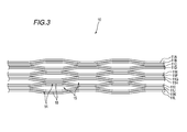
- FIG. 3 shows an example of the optical fiber ribbon fiber 10 accommodated inside the coating 30 of the optical fiber unit 1.
- the optical fiber ribbon 10 has a plurality of optical fiber cores arranged in parallel, and the connecting portion 14 in which adjacent optical fiber cores are connected and the adjacent optical fiber cores are connected.
- the non-connected portion 15 is an intermittent connection type optical fiber tape core wire provided intermittently in the longitudinal direction.
- FIG. 3 shows an intermittent connection type optical fiber ribbon in a state in which the optical fibers 11A to 11L are opened in the arrangement direction.
- the portion where the connecting portion 14 and the non-connecting portion 15 are intermittently provided may be between some of the optical fibers as shown in FIG. 3 or between all the optical fibers. It may be.
- the non-connecting portion 15 is not provided between the optical fiber cores 11A and 11B, 11C and 11D, 11E and 11F, 11G and 11H, 11I and 11J, and 11K and 11L.
- connection portion 14 in the optical fiber ribbon 10 is formed by applying a connection resin 16 made of, for example, an ultraviolet curable resin, a thermosetting resin, or the like between the optical fibers.
- a connection resin 16 made of, for example, an ultraviolet curable resin, a thermosetting resin, or the like between the optical fibers.
- the connecting resin 16 By applying the connecting resin 16 between predetermined optical fiber cores, the connecting part 14 and the non-connecting part 15 are intermittently provided, and the optical fiber cores 11A to 11L are integrated in parallel. Ru.
- the connection resin 16 may be applied to only one side of the parallel surface formed by the parallel optical fiber cores 11A to 11L, or may be applied to both sides.
- an optical fiber ribbon may be employed in which the non-connection portion 15 is not formed.
- the optical fiber ribbons 10 are connected to all the optical fiber ribbons 11A to 11L.
- the non-connection portion 15 may be formed by cutting a part with a rotary blade or the like.
- the optical fiber unit 1 configured as described above, a part of the circumferential direction is interrupted and the opening 31 is formed. Therefore, when the internal optical fiber core wire 11 is taken out, the covering is performed starting from the opening 31 It is possible to open 30. Moreover, when taking out the optical fiber core wire 11 inside, the optical fiber unit 1 is not tightened. Therefore, the optical fiber core wire 11 can be easily taken out from the opened opening 31 and can be taken out without damaging the optical fiber core wire 11.
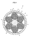
- FIG. 4 shows an example of the optical fiber cable in which the optical fiber unit 1 described above is accommodated.
- the optical fiber cable 40 includes a tension member 41 disposed at the center and a plurality (six in this example) of optical fiber units 1 (1A to 1) disposed around the tension member 41. 1F) and.
- the optical fiber cable 40 further includes a waterproof tape 42 covering the periphery of the optical fiber units 1A to 1F, and an outer sheath 43 covering the periphery of the waterproof tape 42.
- the jacket 43 is formed of a relatively hard material.
- the optical fiber units 1A to 1F of this example are disposed along the longitudinal direction around the tension member 41 without the optical fiber units being twisted together.
- the optical fiber units may be twisted together.
- the optical fiber units 1A to 1F are arranged around the tension member 41 with their outer shapes deformed.
- the optical fiber core wire 11 is used.
- the clamping force applied to 11 can be relaxed. Therefore, the optical fiber core wire 11 can be easily taken out without being damaged.
- FIG. 5 shows another example of the optical fiber cable in which the optical fiber unit 1 described above is accommodated.
- the optical fiber cable 50 has a plurality (five in this example) of optical fiber units 1 (1G to 1K) and an outer sheath 51 covering the circumference of the optical fiber units 1G to 1K. Is equipped.
- a tension member 52 is embedded in the inside of the jacket 51.
- the outer sheath 51 may be provided with a tear cord 53 for tearing the outer sheath 51 at the time of intermediate branching.
- a soft material is used for the outer cover 51 so as to be easily deformed.
- the optical fiber units 1 G to 1 K of this example are twisted together and accommodated inside the outer cover 51. For this reason, each of the optical fiber units 1G to 1K is accommodated in a state where its outer shape is deformed. According to the optical fiber cable 50 having such a configuration, the same effect as the optical fiber cable 40 can be obtained.
- optical fiber unit 10 optical fiber tape core wire 11 (11A to 11L): optical fiber core wire 14: connection portion 15: non-connection portion 16: connection resin 20: aggregate 30: coating 31: Opening 40, 50: Optical fiber cable 43, 51: Outer jacket
Landscapes
- Physics & Mathematics (AREA)
- General Physics & Mathematics (AREA)
- Optics & Photonics (AREA)
- Light Guides In General And Applications Therefor (AREA)
Abstract
複数本の光ファイバ心線が並列に配置された複数の光ファイバテープ心線が集められた集合体と、内側に空間を有する状態で集合体の周囲を覆う被覆と、有する光ファイバユニットであって、被覆は、光ファイバユニットの周方向の一部が途切れ、開口部が形成されている。
Description
本開示は、光ファイバユニットおよび光ファイバケーブルに関する。
本出願は、2017年11月2日出願の日本出願2017-212768号に基づく優先権を主張し、前記日本出願に記載された全ての記載内容を援用するものである。
本出願は、2017年11月2日出願の日本出願2017-212768号に基づく優先権を主張し、前記日本出願に記載された全ての記載内容を援用するものである。
特許文献1には、光ファイバの集合体を束ねて、複数のバンドル材を長手方向に螺旋状に直接巻回してなる光ファイバユニットが開示されており、複数のバンドル材のいずれか2本が交差している交差点の一部又は全部で、バンドル材同士が接着されていることが記載されている。
本開示の一態様に係る光ファイバユニットは、
複数本の光ファイバ心線が並列に配置された複数の光ファイバテープ心線が集められた集合体と、
内側に空間を有する状態で前記集合体の周囲を覆う被覆と、
を有する光ファイバユニットであって、
前記被覆は、当該光ファイバユニットの周方向の一部が途切れ、開口部が形成されている。
複数本の光ファイバ心線が並列に配置された複数の光ファイバテープ心線が集められた集合体と、
内側に空間を有する状態で前記集合体の周囲を覆う被覆と、
を有する光ファイバユニットであって、
前記被覆は、当該光ファイバユニットの周方向の一部が途切れ、開口部が形成されている。
また、本開示の一態様に係る光ファイバケーブルは、
上記光ファイバユニットを有する。
上記光ファイバユニットを有する。
[本開示が解決しようとする課題]
例えば特許文献1に記載された光ファイバユニットでは、光ファイバ(光ファイバ心線、光ファイバテープ心線等)の束の周囲に、2本(複数)のバンドル材(または識別糸)が互いに交差するように逆向きに巻き付けられている。また、上記2本のバンドル材の交点部は接着されている。
例えば特許文献1に記載された光ファイバユニットでは、光ファイバ(光ファイバ心線、光ファイバテープ心線等)の束の周囲に、2本(複数)のバンドル材(または識別糸)が互いに交差するように逆向きに巻き付けられている。また、上記2本のバンドル材の交点部は接着されている。
ところが、上記のように2本のバンドル材が巻き付けられた光ファイバユニットは、接着された交点部を引き剥がして内部の光ファイバを取り出す際に、誤ってバンドル材を締め付けてしまい、内部の光ファイバを傷つけてしまうおそれがある。また、高密度の光ファイバユニットを光ケーブルに実装する場合や光ファイバユニットに側圧が負荷された場合にバンドル材が光ファイバに食い込み、マイクロベンドロスに繋がりやすい。
本開示は、内部の光ファイバを傷つけずに容易に取り出すことができる光ファイバユニットおよび光ファイバケーブルを提供することを目的とする。
[本開示の効果]
本開示の光ファイバユニットおよび光ファイバケーブルによれば、内部の光ファイバを傷つけずに容易に取り出すことができる。
本開示の光ファイバユニットおよび光ファイバケーブルによれば、内部の光ファイバを傷つけずに容易に取り出すことができる。
(本開示の実施形態の説明)
最初に本開示の実施態様を列記して説明する。
本開示の一態様に係る光ファイバユニットは、
(1)複数本の光ファイバ心線が並列に配置された複数の光ファイバテープ心線が集められた集合体と、
内側に空間を有する状態で前記集合体の周囲を覆う被覆と、
を有する光ファイバユニットであって、
前記被覆は、当該光ファイバユニットの周方向の一部が途切れ、開口部が形成されている。
上記構成によれば、光ファイバユニットの被覆は、光ファイバユニットの周方向の一部で途切れ、開口部が形成されている。開口部があるので、内部の光ファイバが取り出し易く、また、内部の光ファイバを取り出す際に光ファイバユニットを締め付けることがないので、内部の光ファイバを傷つけずに容易に取り出すことができる。
最初に本開示の実施態様を列記して説明する。
本開示の一態様に係る光ファイバユニットは、
(1)複数本の光ファイバ心線が並列に配置された複数の光ファイバテープ心線が集められた集合体と、
内側に空間を有する状態で前記集合体の周囲を覆う被覆と、
を有する光ファイバユニットであって、
前記被覆は、当該光ファイバユニットの周方向の一部が途切れ、開口部が形成されている。
上記構成によれば、光ファイバユニットの被覆は、光ファイバユニットの周方向の一部で途切れ、開口部が形成されている。開口部があるので、内部の光ファイバが取り出し易く、また、内部の光ファイバを取り出す際に光ファイバユニットを締め付けることがないので、内部の光ファイバを傷つけずに容易に取り出すことができる。
(2)前記光ファイバテープ心線は、一部、または全ての前記光ファイバ心線間において、隣接する光ファイバ心線間が連結された連結部と、隣接する光ファイバ心線間が連結されていない非連結部とが長手方向に間欠的に設けられた間欠連結型光ファイバテープ心線であってもよい。
上記構成によれば、光ファイバテープ心線が間欠連結型であるので、集合体の隙間が少なくなるように光ファイバテープ心線を集めて集合体とすることが可能であり、集合体を高密度にすることが容易である。
上記構成によれば、光ファイバテープ心線が間欠連結型であるので、集合体の隙間が少なくなるように光ファイバテープ心線を集めて集合体とすることが可能であり、集合体を高密度にすることが容易である。
(3)前記開口部は、当該光ファイバユニットの長手方向に沿って、螺旋状に形成されていてもよい。
上記構成によれば、光ファイバが挿入される方向に対し、開口部が螺旋状に形成されているので、光ファイバユニットを曲げたときに、意図せず光ファイバが飛び出してくることを防止できる。
上記構成によれば、光ファイバが挿入される方向に対し、開口部が螺旋状に形成されているので、光ファイバユニットを曲げたときに、意図せず光ファイバが飛び出してくることを防止できる。
(4)前記被覆のヤング率は、400MPa以下であってもよい。
上記構成によれば、被覆のヤング率が400MPa以下であるので、光ファイバユニットの外形を変形しやすくできる。これにより、光ファイバユニットの外形を変形させて光ファイバケーブルに高密度に実装することができる。
上記構成によれば、被覆のヤング率が400MPa以下であるので、光ファイバユニットの外形を変形しやすくできる。これにより、光ファイバユニットの外形を変形させて光ファイバケーブルに高密度に実装することができる。
(5)当該光ファイバユニットの周方向の半分以上が前記被覆で覆われていてもよい。
上記構成によれば、光ファイバユニットの周方向の半分以上が被覆で覆われているので、内部からの容易に光ファイバが飛び出してくることを防止できると共に、光ファイバに外傷を与えることを抑制できる。
上記構成によれば、光ファイバユニットの周方向の半分以上が被覆で覆われているので、内部からの容易に光ファイバが飛び出してくることを防止できると共に、光ファイバに外傷を与えることを抑制できる。
(6)前記開口部は、当該光ファイバユニットの長手方向に間欠的に設けられていてもよい。
上記構成によれば、開口部が光ファイバユニットの長手方向に間欠的に設けられているので、光ファイバユニット内の光ファイバがさらに飛び出しにくくなる。
上記構成によれば、開口部が光ファイバユニットの長手方向に間欠的に設けられているので、光ファイバユニット内の光ファイバがさらに飛び出しにくくなる。
(7)前記被覆の周囲に巻かれたバンドルを有していてもよい。
上記構成によれば、被覆の周囲にバンドルが巻かれているので、さらに確実に光ファイバの飛び出しを防止できる。
上記構成によれば、被覆の周囲にバンドルが巻かれているので、さらに確実に光ファイバの飛び出しを防止できる。
また、本開示の一態様に係る光ファイバケーブルは、
(8)上記(1)から(7)のいずれか一に記載の光ファイバユニットを有する。
上記構成によれば、光ファイバケーブルを解体して、光ファイバユニットから光ファイバを取り出す際に光ファイバユニットを締め付けることがなく、光ファイバを傷つけずに容易に取り出すことができる。
(8)上記(1)から(7)のいずれか一に記載の光ファイバユニットを有する。
上記構成によれば、光ファイバケーブルを解体して、光ファイバユニットから光ファイバを取り出す際に光ファイバユニットを締め付けることがなく、光ファイバを傷つけずに容易に取り出すことができる。
(本開示の実施形態の詳細)
本開示の実施形態に係る光ファイバユニットおよび光ファイバケーブルの具体例を、以下に図面を参照しつつ説明する。
なお、本開示はこれらの例示に限定されるものではなく、請求の範囲によって示され、請求の範囲と均等の意味および範囲内でのすべての変更が含まれることが意図される。
本開示の実施形態に係る光ファイバユニットおよび光ファイバケーブルの具体例を、以下に図面を参照しつつ説明する。
なお、本開示はこれらの例示に限定されるものではなく、請求の範囲によって示され、請求の範囲と均等の意味および範囲内でのすべての変更が含まれることが意図される。
図1および図2は、本実施形態に係る光ファイバユニットの一例を示す。図1は、光ファイバユニット1の長手方向に垂直な断面図である。図2は、光ファイバユニット1の長手方向の平面図である。
図1に示すように、光ファイバユニット1は、複数の光ファイバテープ心線10が集められた集合体20と、集合体20の周囲を覆う被覆30とを備えている。
図1に示すように、光ファイバユニット1は、複数の光ファイバテープ心線10が集められた集合体20と、集合体20の周囲を覆う被覆30とを備えている。
光ファイバテープ心線10は、複数本(本例では12本)の光ファイバ心線11(11A~11L)が、少なくとも一部を接触させた並列状態で樹脂によって連結されている。各光ファイバ心線11A~11Lは、図示を省略するが、例えば、コアとクラッドで構成されるガラスファイバと、ガラスファイバを被覆する被覆層とで構成されている。
集合体20として集められている光ファイバテープ心線10は、本例では12本の光ファイバ心線11A~11Lが一列に配列された場合よりも配列方向の長さが短くなるように、断面視で複数本の光ファイバ心線11A~11Lが集合した(例えば、丸めたように集合した)集合形態にされている。光ファイバテープ心線10同士は、例えば螺旋状に撚り合わせて集合体20とされていてもよいし、撚り合わせずに集められ集合体20とされていてもよい。
被覆30は、複数の光ファイバテープ心線10が集められた集合体20の周囲を中空状態で覆うように設けられている。「中空状態」とは、集合体20の周囲を薄い層状の被覆部材で覆い、その被覆部材の内側に中空部分が存在している状態を意味する。この中空となっている層状の被覆30の内側に複数の光ファイバテープ心線10が収納されている。
被覆30は、例えばヤング率が400MPa以下である。このため、被覆30を構成とする光ファイバユニット1は、その形状を弾性変形可能な状態に形成されている。被覆30は、熱可塑型樹脂、紫外線硬化型樹脂等で形成されている。例えば被覆30は、エラストマー、低密度ポリエチレン(LDPE)等のプラスチック材料で形成することができる。被覆30の厚さは、0.5mm以下であることが望ましい。
被覆30は、図1に示すように、その断面の外形が例えば円形状となるように形成されている。被覆30は、例えば押出被覆により形成することができる。被覆30には周方向の一部が途切れることによって開口部31が形成されている。開口部31は、その大きさが光ファイバユニット1の周方向の半分よりも小さくなるように形成されている。すなわち、光ファイバユニット1の周方向の半分以上は、被覆30で覆われるように構成されている。
また、開口部31は、図2に示すように、光ファイバユニット1の長手方向に沿って螺旋状に形成されていることが好ましい。開口部31の螺旋状の向きは、本例では、被覆30の内側に収納されている光ファイバテープ心線10同士の螺旋状の撚り合わせの向きと同じ向きとされている。なお、両者の螺旋状の向きは、逆向きとしてもよい。
開口部31は、例えば被覆30の押出被覆時にC型形状のダイスを回転させることで螺旋状に形成することができる。なお、押出被覆で光ファイバユニット1の被覆30を全周に被せた後に、被覆30に切り込みを入れて開口部31を形成するようにしてもよい。
また、本例の開口部31は光ファイバユニット1の長手方向へ沿って連続的に形成されているが、例えばミシン目状に間欠的に設けられていてもよい。さらに、開口部31は、螺旋状に限定されず、例えば長手方向へ沿って直線状に形成されていてもよい。
光ファイバユニット1の被覆30の周囲には、例えばポリエチレンテレフタレート等のテープまたは糸からなるバンドル材(図示省略)が設けられていてもよい。バンドル材は、被覆30の周囲に螺旋状に巻き付けられている。バンドル材が巻き付けられる螺旋状の向きは、開口部31の螺旋状の向きとは逆向きであることが望ましい。
図3は、上記光ファイバユニット1の被覆30の内側に収納される光ファイバテープ心線10の一例を示す。光ファイバテープ心線10は、複数の光ファイバ心線が並列に配置された状態で、隣接する光ファイバ心線間が連結された連結部14と、隣接する光ファイバ心線間が連結されていない非連結部15とが長手方向に間欠的に設けられている間欠連結型の光ファイバテープ心線である。
本例の光ファイバテープ心線10は、12本の光ファイバ心線11A~11Lが並列に配置されている。図3には、光ファイバ心線11A~11Lを配列方向に開いた状態の間欠連結型の光ファイバテープ心線が示されている。連結部14と非連結部15とが間欠的に設けられている箇所は、図3に示すように一部の光ファイバ心線間であってもよく、または、全ての光ファイバ心線間であってもよい。図3に示す例では、光ファイバ心線11Aと11B、11Cと11D、11Eと11F、11Gと11H、11Iと11J、11Kと11L、の各線間には非連結部15が設けられていない。
光ファイバテープ心線10における連結部14は、例えば紫外線硬化型樹脂、熱硬化型樹脂等からなる連結樹脂16を、光ファイバ心線間に塗布することによって形成される。連結樹脂16が所定の光ファイバ心線間に塗布されることにより、連結部14と非連結部15とが間欠的に設けられるとともに、各光ファイバ心線11A~11Lが並列状態で一体化される。なお、連結樹脂16は、並列された光ファイバ心線11A~11Lで形成される並列面の片面のみに塗布するようにしてもよいし、両面に塗布するようにしてもよい。また、非連結部15を形成しない構成の光ファイバテープ心線としてもよい。また、光ファイバテープ心線10は、例えば並列された光ファイバ心線11A~11Lの片面、若しくは両面全体にテープ樹脂16を塗布して、全ての光ファイバ心線11A~11Lを連結させてから、回転刃等で一部を切断して非連結部15を形成するように作製してもよい。
上記のような構成の光ファイバユニット1によれば、周方向の一部が途切れて開口部31が形成されているので、内部の光ファイバ心線11を取り出す際に開口部31を起点として被覆30を切り開くことが可能である。また、内部の光ファイバ心線11を取り出す際に光ファイバユニット1を締め付けることがない。このため、切り開いた開口部31から光ファイバ心線11を容易に取り出すことができるとともに、光ファイバ心線11を傷つけずに取り出すことができる。
図4は、上述した光ファイバユニット1が収納された光ファイバケーブルの一例を示す。図4に示すように、光ファイバケーブル40は、中心部に配置されたテンションメンバ41と、テンションメンバ41の周囲に配置された複数本(本例では6本)の光ファイバユニット1(1A~1F)とを備えている。また、光ファイバケーブル40は、これらの光ファイバユニット1A~1Fの周囲を覆う防水テープ42と、防水テープ42の周囲を覆う外被43とを備えている。外被43は、比較的硬い材質のもので形成されている。
本例の光ファイバユニット1A~1Fは、光ファイバユニット同士が撚り合わされずにテンションメンバ41の周囲に長手方向へ沿って配置されている。なお、光ファイバユニット同士は撚り合わされてもよく、撚り合わせた場合には、各光ファイバユニット1A~1Fは、それぞれ外形が変形した状態となってテンションメンバ41の周囲に配置される。
このような構成の光ファイバケーブル40によれば、光ファイバユニット1が用いられているので、光ファイバケーブル40を解体して光ファイバユニット1から光ファイバ心線11を取り出す際に光ファイバ心線11に加わる締め付け力を緩和できる。このため、光ファイバ心線11を傷つけずに容易に取り出すことができる。
図5は、上述した光ファイバユニット1が収納された光ファイバケーブルの別の一例を示す。図5に示すように、光ファイバケーブル50は、複数本(本例では5本)の光ファイバユニット1(1G~1K)と、これらの光ファイバユニット1G~1Kの周囲を覆う外被51とを備えている。外被51の内部にはテンションメンバ52が埋め込まれている。また、外被51には、中間分岐時に外被51を引き裂くための引き裂き紐53が設けられていてもよい。光ファイバケーブル50では、より高密度に光ファイバを実装するために、外被51に軟質材を用いて変形容易な構成としている。
本例の光ファイバユニット1G~1Kは、光ファイバユニット同士が撚り合わされて、外被51の内側に収納されている。このため、各光ファイバユニット1G~1Kは、それぞれ外形が変形した状態で収納されている。
このような構成の光ファイバケーブル50によれば、上記光ファイバケーブル40と同様の効果を奏する。
このような構成の光ファイバケーブル50によれば、上記光ファイバケーブル40と同様の効果を奏する。
以上、本開示を詳細にまた特定の実施態様を参照して説明したが、本開示の精神と範囲を逸脱することなく様々な変更や修正を加えることができることは当業者にとって明らかである。また、上記説明した構成部材の数、位置、形状等は上記実施の形態に限定されず、本開示を実施する上で好適な数、位置、形状等に変更することができる。
1(1A~1F):光ファイバユニット
10:光ファイバテープ心線
11(11A~11L):光ファイバ心線
14:連結部
15:非連結部
16:連結樹脂
20:集合体
30:被覆
31:開口部
40,50:光ファイバケーブル
43,51:外被
10:光ファイバテープ心線
11(11A~11L):光ファイバ心線
14:連結部
15:非連結部
16:連結樹脂
20:集合体
30:被覆
31:開口部
40,50:光ファイバケーブル
43,51:外被
Claims (8)
- 複数本の光ファイバ心線が並列に配置された複数の光ファイバテープ心線が集められた集合体と、
内側に空間を有する状態で前記集合体の周囲を覆う被覆と、
を有する光ファイバユニットであって、
前記被覆は、当該光ファイバユニットの周方向の一部が途切れ、開口部が形成されている、
光ファイバユニット。 - 前記光ファイバテープ心線は、一部、または全ての前記光ファイバ心線間において、隣接する光ファイバ心線間が連結された連結部と、隣接する光ファイバ心線間が連結されていない非連結部とが長手方向に間欠的に設けられた間欠連結型光ファイバテープ心線である、
請求項1に記載の光ファイバユニット。 - 前記開口部は、当該光ファイバユニットの長手方向に沿って、螺旋状に形成されている、
請求項1または請求項2に記載の光ファイバユニット。 - 前記被覆のヤング率は、400MPa以下である、
請求項1から請求項3のいずれか一項に記載の光ファイバユニット。 - 当該光ファイバユニットの周方向の半分以上が前記被覆で覆われている、
請求項1から請求項4のいずれか一項に記載の光ファイバユニット。 - 前記開口部は、当該光ファイバユニットの長手方向に間欠的に設けられている、
請求項1から請求項5のいずれか一項に記載の光ファイバユニット。 - 前記被覆の周囲に巻かれたバンドルを有する、
請求項1から請求項6のいずれか一項に記載の光ファイバユニット。 - 請求項1から請求項7のいずれか一項に記載の光ファイバユニットを有する、
光ファイバケーブル。
Priority Applications (3)
| Application Number | Priority Date | Filing Date | Title |
|---|---|---|---|
| US16/759,760 US11307370B2 (en) | 2017-11-02 | 2018-11-02 | Optical fiber unit and optical fiber cable |
| JP2019550497A JP7192782B2 (ja) | 2017-11-02 | 2018-11-02 | 光ファイバユニットおよび光ファイバケーブル |
| EP18872603.8A EP3705924B1 (en) | 2017-11-02 | 2018-11-02 | Optical fiber unit and optical fiber cable |
Applications Claiming Priority (2)
| Application Number | Priority Date | Filing Date | Title |
|---|---|---|---|
| JP2017-212768 | 2017-11-02 | ||
| JP2017212768 | 2017-11-02 |
Publications (1)
| Publication Number | Publication Date |
|---|---|
| WO2019088255A1 true WO2019088255A1 (ja) | 2019-05-09 |
Family
ID=66332000
Family Applications (1)
| Application Number | Title | Priority Date | Filing Date |
|---|---|---|---|
| PCT/JP2018/040847 Ceased WO2019088255A1 (ja) | 2017-11-02 | 2018-11-02 | 光ファイバユニットおよび光ファイバケーブル |
Country Status (4)
| Country | Link |
|---|---|
| US (1) | US11307370B2 (ja) |
| EP (1) | EP3705924B1 (ja) |
| JP (1) | JP7192782B2 (ja) |
| WO (1) | WO2019088255A1 (ja) |
Cited By (6)
| Publication number | Priority date | Publication date | Assignee | Title |
|---|---|---|---|---|
| JPWO2021049626A1 (ja) * | 2019-09-11 | 2021-03-18 | ||
| US20220373753A1 (en) * | 2020-03-27 | 2022-11-24 | Furukawa Electric Co., Ltd. | Optical Fiber Cable |
| EP4177652A4 (en) * | 2020-07-01 | 2024-07-24 | Fujikura Ltd. | OPTICAL CABLE AND ITS MANUFACTURING METHOD |
| WO2024241470A1 (ja) * | 2023-05-23 | 2024-11-28 | 日本電信電話株式会社 | 光ファイバケーブル |
| WO2025146711A1 (ja) * | 2024-01-04 | 2025-07-10 | 住友電気工業株式会社 | 光ファイバユニットおよび光ファイバケーブル |
| JP2025541904A (ja) * | 2022-12-23 | 2025-12-23 | エルエス ケーブル アンド システム リミテッド. | 光ファイバーリボン |
Families Citing this family (1)
| Publication number | Priority date | Publication date | Assignee | Title |
|---|---|---|---|---|
| WO2019088255A1 (ja) | 2017-11-02 | 2019-05-09 | 住友電気工業株式会社 | 光ファイバユニットおよび光ファイバケーブル |
Citations (12)
| Publication number | Priority date | Publication date | Assignee | Title |
|---|---|---|---|---|
| US20050013573A1 (en) | 2003-07-18 | 2005-01-20 | Lochkovic Gregory A. | Fiber optic articles, assemblies, and cables having optical waveguides |
| US20060193575A1 (en) | 2005-02-28 | 2006-08-31 | Greenwood Jody L | Loose tube fiber optic cables having at least one access location |
| JP2007010917A (ja) * | 2005-06-29 | 2007-01-18 | Sumitomo Electric Ind Ltd | 光ファイバユニット、光ファイバユニットの製造方法並びに光ファイバケーブル |
| US20070098339A1 (en) | 2002-12-19 | 2007-05-03 | Bringuier Anne G | Dry fiber optic cables and assemblies |
| JP2009271301A (ja) * | 2008-05-07 | 2009-11-19 | Advanced Cable Systems Corp | テープスロット型光ファイバケーブルおよび中間後分岐作業方法 |
| WO2010106858A1 (ja) | 2009-03-16 | 2010-09-23 | 株式会社フジクラ | 光ファイバケーブル |
| JP2010256793A (ja) * | 2009-04-28 | 2010-11-11 | Sumitomo Electric Ind Ltd | 光ケーブル |
| JP2011169939A (ja) | 2010-02-16 | 2011-09-01 | Furukawa Electric Co Ltd:The | 光ファイバユニット及び光ファイバケーブル |
| JP2014016529A (ja) * | 2012-07-10 | 2014-01-30 | Sumitomo Electric Ind Ltd | 光ファイバケーブル |
| JP2017212768A (ja) | 2016-05-23 | 2017-11-30 | 住友電装株式会社 | ワイヤーハーネス用結束部材、結束部材付ワイヤーハーネス |
| US20190049681A1 (en) | 2017-08-08 | 2019-02-14 | Corning Research & Development Corporation | Rollable optical fiber ribbon with low attenuation, large mode field diameter optical fiber and cable |
| EP3705924A1 (en) | 2017-11-02 | 2020-09-09 | Sumitomo Electric Industries, Ltd. | Optical fiber unit and optical fiber cable |
Family Cites Families (45)
| Publication number | Priority date | Publication date | Assignee | Title |
|---|---|---|---|---|
| CH662231A5 (de) * | 1982-09-13 | 1987-09-15 | Eilentropp Hew Kabel | Flexibles elektrisches ablaengbares heiz- oder temperaturmesselement. |
| GB8605016D0 (en) * | 1986-02-28 | 1986-04-09 | Bicc Plc | Optical cable |
| DE3811126A1 (de) * | 1988-03-31 | 1989-10-12 | Siemens Ag | Optisches kabel mit mehreren buendelelementen |
| JPH087295B2 (ja) * | 1988-07-13 | 1996-01-29 | 住友電気工業株式会社 | 光分岐結合器の製造方法 |
| US5071221A (en) * | 1988-08-05 | 1991-12-10 | Mitsubishi Petrochemical Company Limited | Water penetration preventive cable |
| US5249249A (en) * | 1991-08-27 | 1993-09-28 | Siecor Corporation | Cable utilizing multiple light waveguide stacks |
| JP3320937B2 (ja) * | 1995-03-06 | 2002-09-03 | 住友電気工業株式会社 | 光ケーブル |
| JP4086978B2 (ja) * | 1998-09-17 | 2008-05-14 | 古河電気工業株式会社 | 光ファイバケーブル |
| KR100322123B1 (ko) * | 1998-11-18 | 2002-03-08 | 윤종용 | 스틸튜브를이용한광섬유복합가공지선 |
| US6561229B2 (en) * | 2000-06-26 | 2003-05-13 | Raymond L. Wellman | Electrostatic charge neutralizing fume duct with continuous carbon fiber |
| JP3578076B2 (ja) * | 2000-10-13 | 2004-10-20 | 住友電気工業株式会社 | 自己支持型ケーブル及びその製造方法 |
| US6828373B2 (en) * | 2001-03-07 | 2004-12-07 | Advanced Ceramics Research, Inc. | Water soluble tooling materials for composite structures |
| US6760523B2 (en) * | 2001-06-20 | 2004-07-06 | Alcatel | Tape based high fiber count cable |
| CN1653370A (zh) * | 2002-05-17 | 2005-08-10 | 住友电气工业株式会社 | 带状光纤心线、其制造方法、含带状心线连接器、含带状心线光纤阵列、以及光布线系统 |
| US7151879B2 (en) * | 2002-11-06 | 2006-12-19 | Sumitomo Electric Industries, Ltd. | Optical fiber ribbon that is easily branched into individual optical fibers and optical fiber cable using the same |
| US8152839B2 (en) * | 2005-12-19 | 2012-04-10 | Boston Scientific Scimed, Inc. | Embolic coils |
| JP4805010B2 (ja) | 2006-05-11 | 2011-11-02 | 古河電気工業株式会社 | 光ファイバケーブル |
| JP4943993B2 (ja) | 2007-10-31 | 2012-05-30 | パイオニア株式会社 | ナビゲーション装置、ナビゲーション方法、ナビゲーションプログラム、および記録媒体 |
| JP2009116017A (ja) | 2007-11-06 | 2009-05-28 | Sumitomo Electric Ind Ltd | 光ケーブル及び光ケーブルの製造方法 |
| WO2010001663A1 (ja) * | 2008-06-30 | 2010-01-07 | 日本電信電話株式会社 | 光ファイバケーブル及び光ファイバテープ |
| JP5448699B2 (ja) | 2008-10-14 | 2014-03-19 | Sdpグローバル株式会社 | 吸収性樹脂粒子、この製造方法、これを含む吸収体及び吸収性物品 |
| JP2010243623A (ja) | 2009-04-02 | 2010-10-28 | Sumitomo Electric Ind Ltd | 光ケーブルの製造方法 |
| JP2010276632A (ja) | 2009-05-26 | 2010-12-09 | Sumitomo Electric Ind Ltd | 光ケーブルの製造方法 |
| JP5227996B2 (ja) * | 2010-04-05 | 2013-07-03 | 株式会社フジクラ | 光ファイバテープ心線、光ファイバケーブル及び配線形態 |
| JP2012128236A (ja) | 2010-12-16 | 2012-07-05 | Sumitomo Electric Ind Ltd | 光ケーブル |
| JP5272066B2 (ja) | 2011-03-23 | 2013-08-28 | 株式会社フジクラ | 光ファイバユニット、光ファイバユニットの製造方法、光ファイバユニットを用いた光ファイバーケーブル |
| JP2013025028A (ja) | 2011-07-20 | 2013-02-04 | Sumitomo Electric Ind Ltd | 光ケーブル |
| US9170388B2 (en) * | 2011-09-30 | 2015-10-27 | Corning Cable Systems Llc | Fiber optic ribbon cable having enhanced ribbon stack coupling and methods thereof |
| JP2013097320A (ja) | 2011-11-04 | 2013-05-20 | Fujikura Ltd | 光ファイバユニット、光ファイバケーブル、光ファイバユニットの製造方法及び光ファイバケーブルの製造方法 |
| JP5735399B2 (ja) | 2011-11-07 | 2015-06-17 | 株式会社フジクラ | 光ファイバケーブル及びその製造方法 |
| JP2013182094A (ja) | 2012-03-01 | 2013-09-12 | Sumitomo Electric Ind Ltd | 光ケーブル |
| JP5914057B2 (ja) | 2012-03-08 | 2016-05-11 | 株式会社フジクラ | 光ファイバユニットの作製方法及び光ファイバケーブルの製造方法 |
| JP5902007B2 (ja) | 2012-03-12 | 2016-04-13 | 株式会社フジクラ | 光ファイバケーブル及び光ファイバケーブルの製造方法 |
| JP2014119524A (ja) | 2012-12-14 | 2014-06-30 | Sumitomo Electric Ind Ltd | 光ケーブル |
| JP2014119635A (ja) | 2012-12-18 | 2014-06-30 | Sumitomo Electric Ind Ltd | 光ケーブル |
| JP6257156B2 (ja) | 2013-03-04 | 2018-01-10 | オリンパス株式会社 | 顕微鏡装置 |
| JP2014211511A (ja) * | 2013-04-18 | 2014-11-13 | 住友電気工業株式会社 | 光ケーブル |
| JP6268774B2 (ja) | 2013-07-10 | 2018-01-31 | 住友電気工業株式会社 | 光ケーブル |
| JP2015040990A (ja) | 2013-08-22 | 2015-03-02 | 住友電気工業株式会社 | 光ケーブル |
| JP6191343B2 (ja) | 2013-09-06 | 2017-09-06 | 住友電気工業株式会社 | 光ケーブル |
| JP6442161B2 (ja) | 2014-05-13 | 2018-12-19 | 株式会社フジクラ | 光ケーブル及び光ケーブルの製造方法 |
| JP2016061871A (ja) * | 2014-09-17 | 2016-04-25 | 古河電気工業株式会社 | 光ファイバケーブル |
| JP2017009924A (ja) | 2015-06-25 | 2017-01-12 | 古河電気工業株式会社 | 光ファイバユニット、光ファイバケーブル、および光ファイバユニットの製造方法 |
| JP2017037214A (ja) | 2015-08-11 | 2017-02-16 | 住友電気工業株式会社 | 光ケーブルおよびその製造方法 |
| EP3385765A4 (en) * | 2015-12-01 | 2019-08-21 | Furukawa Electric Co. Ltd. | CENTRAL FIBER OPTIC RIBBON WIRE AND OPTICAL FIBER CABLE |
-
2018
- 2018-11-02 WO PCT/JP2018/040847 patent/WO2019088255A1/ja not_active Ceased
- 2018-11-02 US US16/759,760 patent/US11307370B2/en active Active
- 2018-11-02 JP JP2019550497A patent/JP7192782B2/ja active Active
- 2018-11-02 EP EP18872603.8A patent/EP3705924B1/en active Active
Patent Citations (43)
| Publication number | Priority date | Publication date | Assignee | Title |
|---|---|---|---|---|
| US7471862B2 (en) | 2002-12-19 | 2008-12-30 | Corning Cable Systems, Llc | Dry fiber optic cables and assemblies |
| US20070098339A1 (en) | 2002-12-19 | 2007-05-03 | Bringuier Anne G | Dry fiber optic cables and assemblies |
| US20090074364A1 (en) | 2002-12-19 | 2009-03-19 | Bringuier Anne G | Dry Fiber Optic Cables and Assemblies |
| WO2005010565A2 (en) | 2003-07-18 | 2005-02-03 | Corning Cable Systems Llc | Fiber optic articles, assemblies, and cables having optical waveguides |
| EP1646901A2 (en) | 2003-07-18 | 2006-04-19 | Corning Cable Systems LLC | Fiber optic articles, assemblies, and cables having optical waveguides |
| US7050688B2 (en) | 2003-07-18 | 2006-05-23 | Corning Cable Systems Llc | Fiber optic articles, assemblies, and cables having optical waveguides |
| CN100498392C (zh) | 2003-07-18 | 2009-06-10 | 康宁光缆系统有限公司 | 具有光波导的光纤制品、组件及电缆 |
| CN1950736A (zh) | 2003-07-18 | 2007-04-18 | 康宁光缆系统有限公司 | 具有光波导的光纤制品、组件及电缆 |
| US20050013573A1 (en) | 2003-07-18 | 2005-01-20 | Lochkovic Gregory A. | Fiber optic articles, assemblies, and cables having optical waveguides |
| US20060193575A1 (en) | 2005-02-28 | 2006-08-31 | Greenwood Jody L | Loose tube fiber optic cables having at least one access location |
| US7203404B2 (en) | 2005-02-28 | 2007-04-10 | Corning Cable Systems, Llc. | Loose tube fiber optic cables having at least one access location |
| JP2007010917A (ja) * | 2005-06-29 | 2007-01-18 | Sumitomo Electric Ind Ltd | 光ファイバユニット、光ファイバユニットの製造方法並びに光ファイバケーブル |
| US9971101B2 (en) | 2005-07-29 | 2018-05-15 | Corning Optical Communications LLC | Fiber optic cable assembly |
| US20100290747A1 (en) | 2005-07-29 | 2010-11-18 | Bringuier Anne G | Dry Fiber Optic Cables and Assemblies |
| US20170031107A1 (en) | 2005-07-29 | 2017-02-02 | Corning Optical Communications LLC | Fiber optic cable assembly |
| US9494755B2 (en) | 2005-07-29 | 2016-11-15 | Corning Optical Communications LLC | Fiber optic cable assembly |
| US9482837B2 (en) | 2005-07-29 | 2016-11-01 | Corning Cable Systems Llc | Dry fiber optic cables and assemblies |
| US20090324183A1 (en) | 2005-07-29 | 2009-12-31 | Bringuier Anne G | Dry Fiber Optic Cables and Assemblies |
| US7787727B2 (en) | 2005-07-29 | 2010-08-31 | Corning Cable Systems Llc | Dry fiber optic cables and assemblies |
| US9477057B2 (en) | 2005-07-29 | 2016-10-25 | Corning Optical Communications LLC | Fiber optic cables and assemblies |
| US20140241678A1 (en) | 2005-07-29 | 2014-08-28 | Corning Optical Communications LLC | Fiber optic cable assembly |
| US20140212101A1 (en) | 2005-07-29 | 2014-07-31 | Corning Optical Communications LLC | Fiber optic cables and assemblies |
| AU2007334346A1 (en) | 2006-12-21 | 2008-06-26 | Corning Cable Systems Llc | Dry fiber optic cables and assemblies |
| WO2008076450A1 (en) | 2006-12-21 | 2008-06-26 | Corning Cable Systems Llc | Dry fiber optic cables and assemblies |
| AU2007101252A4 (en) | 2006-12-21 | 2011-12-01 | Corning Cable Systems Llc | Dry fiber optic cables and assemblies |
| CN101529297A (zh) | 2006-12-21 | 2009-09-09 | 康宁光缆系统有限公司 | 干式光缆及组件 |
| EP2095164A1 (en) | 2006-12-21 | 2009-09-02 | Corning Cable Systems LLC | Dry fiber optic cables and assemblies |
| JP2009271301A (ja) * | 2008-05-07 | 2009-11-19 | Advanced Cable Systems Corp | テープスロット型光ファイバケーブルおよび中間後分岐作業方法 |
| JP2010217392A (ja) | 2009-03-16 | 2010-09-30 | Fujikura Ltd | 光ファイバケーブル |
| WO2010106858A1 (ja) | 2009-03-16 | 2010-09-23 | 株式会社フジクラ | 光ファイバケーブル |
| TW201100890A (en) | 2009-03-16 | 2011-01-01 | Fujikura Ltd | Optical fiber cable |
| JP2010256793A (ja) * | 2009-04-28 | 2010-11-11 | Sumitomo Electric Ind Ltd | 光ケーブル |
| JP2011169939A (ja) | 2010-02-16 | 2011-09-01 | Furukawa Electric Co Ltd:The | 光ファイバユニット及び光ファイバケーブル |
| JP2014016529A (ja) * | 2012-07-10 | 2014-01-30 | Sumitomo Electric Ind Ltd | 光ファイバケーブル |
| JP2017212768A (ja) | 2016-05-23 | 2017-11-30 | 住友電装株式会社 | ワイヤーハーネス用結束部材、結束部材付ワイヤーハーネス |
| US20190049681A1 (en) | 2017-08-08 | 2019-02-14 | Corning Research & Development Corporation | Rollable optical fiber ribbon with low attenuation, large mode field diameter optical fiber and cable |
| WO2019032332A1 (en) | 2017-08-08 | 2019-02-14 | Corning Research & Development Corporation | RIBBON FIBER RIBBON WITH LOW MITIGATION, OPTICAL FIBER WITH LARGE DIAMETER OF FASHION FIELD AND CABLE |
| US10649163B2 (en) | 2017-08-08 | 2020-05-12 | Corning Research & Development Corporation | Rollable optical fiber ribbon with low attenuation, large mode field diameter optical fiber and cable |
| EP3665521A1 (en) | 2017-08-08 | 2020-06-17 | Corning Research & Development Corporation | Rollable optical fiber ribbon with low attenuation, large mode field diameter optical fiber and cable |
| US20200249406A1 (en) | 2017-08-08 | 2020-08-06 | Corning Research & Development Corporation | Rollable optical fiber ribbon with low attenuation, large mode field diameter optical fiber and cable |
| US10948674B2 (en) | 2017-08-08 | 2021-03-16 | Corning Research & Development Corporation | Rollable optical fiber ribbon with low attenuation, large mode field diameter optical fiber and cable |
| US20210165178A1 (en) | 2017-08-08 | 2021-06-03 | Corning Research & Development Corporation | Rollable optical fiber ribbon with low attenuation, large mode field diameter optical fiber and cable |
| EP3705924A1 (en) | 2017-11-02 | 2020-09-09 | Sumitomo Electric Industries, Ltd. | Optical fiber unit and optical fiber cable |
Non-Patent Citations (1)
| Title |
|---|
| See also references of EP3705924A4 |
Cited By (8)
| Publication number | Priority date | Publication date | Assignee | Title |
|---|---|---|---|---|
| JPWO2021049626A1 (ja) * | 2019-09-11 | 2021-03-18 | ||
| US20220373753A1 (en) * | 2020-03-27 | 2022-11-24 | Furukawa Electric Co., Ltd. | Optical Fiber Cable |
| US12292610B2 (en) * | 2020-03-27 | 2025-05-06 | Furukawa Electric Co., Ltd. | Optical fiber cable |
| EP4177652A4 (en) * | 2020-07-01 | 2024-07-24 | Fujikura Ltd. | OPTICAL CABLE AND ITS MANUFACTURING METHOD |
| US12292613B2 (en) | 2020-07-01 | 2025-05-06 | Fujikura Ltd. | Optical cable and optical-cable manufacturing method |
| JP2025541904A (ja) * | 2022-12-23 | 2025-12-23 | エルエス ケーブル アンド システム リミテッド. | 光ファイバーリボン |
| WO2024241470A1 (ja) * | 2023-05-23 | 2024-11-28 | 日本電信電話株式会社 | 光ファイバケーブル |
| WO2025146711A1 (ja) * | 2024-01-04 | 2025-07-10 | 住友電気工業株式会社 | 光ファイバユニットおよび光ファイバケーブル |
Also Published As
| Publication number | Publication date |
|---|---|
| EP3705924B1 (en) | 2022-10-19 |
| EP3705924A1 (en) | 2020-09-09 |
| EP3705924A4 (en) | 2021-08-04 |
| JP7192782B2 (ja) | 2022-12-20 |
| JPWO2019088255A1 (ja) | 2020-11-12 |
| US20210181440A1 (en) | 2021-06-17 |
| US11307370B2 (en) | 2022-04-19 |
Similar Documents
| Publication | Publication Date | Title |
|---|---|---|
| WO2019088255A1 (ja) | 光ファイバユニットおよび光ファイバケーブル | |
| US10268015B2 (en) | Optical fiber cable having a plurality of stranded optical fiber ribbons | |
| JP6674893B2 (ja) | 外装材付き光ファイバケーブル | |
| ES2914224T3 (es) | Tubo suelto, cable de fibra óptica de tipo tubo suelto, método de aislamiento de fibra única para cinta de fibra óptica de tubo suelto, método de fabricación de tubo suelto y método para reunir una pluralidad de fibras ópticas | |
| JP5272066B2 (ja) | 光ファイバユニット、光ファイバユニットの製造方法、光ファイバユニットを用いた光ファイバーケーブル | |
| WO2011059065A1 (ja) | 光ファイバケーブル及びこの光ファイバケーブルの製造方法 | |
| JP7151727B2 (ja) | 光ファイバケーブル | |
| JP2014119635A (ja) | 光ケーブル | |
| WO2020145129A1 (ja) | 光ファイバケーブル、ケーブルコアの製造方法 | |
| WO2022092019A1 (ja) | 光ファイバケーブルおよびコネクタ付きケーブル | |
| WO2019088256A1 (ja) | 光ファイバユニットおよび光ファイバケーブル | |
| JP7200947B2 (ja) | 光ファイバケーブルおよび光ファイバケーブルの製造方法 | |
| KR20200106570A (ko) | 광섬유 유닛 및 광섬유 케이블 | |
| US11435543B2 (en) | Optical fiber unit and optical fiber cable | |
| JP5568071B2 (ja) | 光ファイバケーブル | |
| JP6413593B2 (ja) | 光ファイバケーブル | |
| JP2019056837A (ja) | 光ファイバケーブル | |
| JP2014228821A (ja) | 光ファイバケーブル | |
| JP2007148181A (ja) | 光ファイバケーブル | |
| JP2014119524A (ja) | 光ケーブル | |
| JP2004212960A (ja) | 光ファイバケーブル | |
| JP2012173398A (ja) | 光ケーブル | |
| JP2010128169A (ja) | 光ファイバケーブル | |
| JP2004144960A (ja) | 光ファイバケーブル | |
| JP2018132541A (ja) | 光ファイバケーブル |
Legal Events
| Date | Code | Title | Description |
|---|---|---|---|
| 121 | Ep: the epo has been informed by wipo that ep was designated in this application |
Ref document number: 18872603 Country of ref document: EP Kind code of ref document: A1 |
|
| ENP | Entry into the national phase |
Ref document number: 2019550497 Country of ref document: JP Kind code of ref document: A |
|
| NENP | Non-entry into the national phase |
Ref country code: DE |
|
| ENP | Entry into the national phase |
Ref document number: 2018872603 Country of ref document: EP Effective date: 20200602 |