WO2019088255A1 - Unité de fibre optique et câble à fibre optique - Google Patents
Unité de fibre optique et câble à fibre optique Download PDFInfo
- Publication number
- WO2019088255A1 WO2019088255A1 PCT/JP2018/040847 JP2018040847W WO2019088255A1 WO 2019088255 A1 WO2019088255 A1 WO 2019088255A1 JP 2018040847 W JP2018040847 W JP 2018040847W WO 2019088255 A1 WO2019088255 A1 WO 2019088255A1
- Authority
- WO
- WIPO (PCT)
- Prior art keywords
- optical fiber
- fiber unit
- coating
- unit
- opening
- Prior art date
- Legal status (The legal status is an assumption and is not a legal conclusion. Google has not performed a legal analysis and makes no representation as to the accuracy of the status listed.)
- Ceased
Links
Images



Classifications
-
- G—PHYSICS
- G02—OPTICS
- G02B—OPTICAL ELEMENTS, SYSTEMS OR APPARATUS
- G02B6/00—Light guides; Structural details of arrangements comprising light guides and other optical elements, e.g. couplings
- G02B6/44—Mechanical structures for providing tensile strength and external protection for fibres, e.g. optical transmission cables
- G02B6/4401—Optical cables
- G02B6/4429—Means specially adapted for strengthening or protecting the cables
- G02B6/443—Protective covering
- G02B6/4431—Protective covering with provision in the protective covering, e.g. weak line, for gaining access to one or more fibres, e.g. for branching or tapping
-
- G—PHYSICS
- G02—OPTICS
- G02B—OPTICAL ELEMENTS, SYSTEMS OR APPARATUS
- G02B6/00—Light guides; Structural details of arrangements comprising light guides and other optical elements, e.g. couplings
- G02B6/44—Mechanical structures for providing tensile strength and external protection for fibres, e.g. optical transmission cables
-
- G—PHYSICS
- G02—OPTICS
- G02B—OPTICAL ELEMENTS, SYSTEMS OR APPARATUS
- G02B6/00—Light guides; Structural details of arrangements comprising light guides and other optical elements, e.g. couplings
- G02B6/44—Mechanical structures for providing tensile strength and external protection for fibres, e.g. optical transmission cables
- G02B6/4401—Optical cables
- G02B6/4403—Optical cables with ribbon structure
-
- G—PHYSICS
- G02—OPTICS
- G02B—OPTICAL ELEMENTS, SYSTEMS OR APPARATUS
- G02B6/00—Light guides; Structural details of arrangements comprising light guides and other optical elements, e.g. couplings
- G02B6/44—Mechanical structures for providing tensile strength and external protection for fibres, e.g. optical transmission cables
- G02B6/4401—Optical cables
- G02B6/4405—Optical cables with longitudinally spaced waveguide clamping
-
- G—PHYSICS
- G02—OPTICS
- G02B—OPTICAL ELEMENTS, SYSTEMS OR APPARATUS
- G02B6/00—Light guides; Structural details of arrangements comprising light guides and other optical elements, e.g. couplings
- G02B6/44—Mechanical structures for providing tensile strength and external protection for fibres, e.g. optical transmission cables
- G02B6/4401—Optical cables
- G02B6/441—Optical cables built up from sub-bundles
Definitions
- the present disclosure relates to an optical fiber unit and an optical fiber cable.
- This application claims priority based on Japanese Patent Application No. 2017-212768 filed on Nov. 2, 2017, and incorporates all the contents described in the aforementioned Japanese Patent Application.
- Patent Document 1 discloses an optical fiber unit formed by bundling an assembly of optical fibers and directly winding a plurality of bundle materials helically in the longitudinal direction, and any two of the plurality of bundle materials are It is described that the bundling materials are adhered to each other at a part or all of the crossing points which intersect each other.
- An optical fiber unit is An assembly of a plurality of optical fiber ribbons in which a plurality of optical fibers are arranged in parallel; A coating covering the periphery of the assembly with a space inside; An optical fiber unit having In the coating, a part of the circumferential direction of the optical fiber unit is broken, and an opening is formed.
- optical fiber cable according to one aspect of the present disclosure is The optical fiber unit is provided.
- the optical fiber unit in which the two bundle materials are wound erroneously clamps the bundle material when the bonded optical fiber is pulled out by peeling off the bonded intersection, and the internal light There is a risk of damaging the fiber.
- the bundle material bites into the optical fiber and easily leads to microbend loss.
- the present disclosure aims to provide an optical fiber unit and an optical fiber cable that can be easily taken out without damaging the internal optical fiber.
- the internal optical fiber can be easily taken out without damage.
- An optical fiber unit is (1) A collection of a plurality of optical fiber ribbons in which a plurality of optical fibers are arranged in parallel; A coating covering the periphery of the assembly with a space inside; An optical fiber unit having In the coating, a part of the circumferential direction of the optical fiber unit is broken, and an opening is formed.
- the coating of the optical fiber unit is interrupted in a part of the circumferential direction of the optical fiber unit, and the opening is formed. Since the opening portion is provided, the internal optical fiber can be easily taken out, and since the optical fiber unit is not clamped when the internal optical fiber is taken out, the internal optical fiber can be easily taken out without damaging it.
- the optical fiber ribbons are connected between the connecting portion in which the adjacent optical fibers are connected and between the adjacent optical fibers, between some or all of the optical fibers. It may be an intermittent connection type optical fiber tape core in which non-connected parts are intermittently provided in the longitudinal direction. According to the above configuration, since the optical fiber ribbons are intermittently connected, it is possible to collect the optical fiber ribbons to form an assembly so that the gap between the assemblies is reduced. It is easy to make the density.
- the opening may be formed spirally along the longitudinal direction of the optical fiber unit. According to the above configuration, since the opening is formed in a spiral shape in the direction in which the optical fiber is inserted, it is possible to prevent the optical fiber from unintentionally popping out when the optical fiber unit is bent. .
- the Young's modulus of the coating may be 400 MPa or less. According to the above configuration, since the Young's modulus of the coating is 400 MPa or less, the outer shape of the optical fiber unit can be easily deformed. Thus, the outer shape of the optical fiber unit can be deformed and mounted on the optical fiber cable at high density.
- More than half of the circumferential direction of the optical fiber unit may be covered with the coating. According to the above configuration, more than half of the circumferential direction of the optical fiber unit is covered with the coating, so it is possible to prevent the optical fiber from popping out easily from the inside and to suppress the trauma to the optical fiber it can.
- the opening may be intermittently provided in the longitudinal direction of the optical fiber unit. According to the above configuration, since the opening is provided intermittently in the longitudinal direction of the optical fiber unit, the optical fiber in the optical fiber unit is more unlikely to pop out.
- the optical fiber cable according to one aspect of the present disclosure is (8) It has the optical fiber unit as described in any one of said (1) to (7). According to the above configuration, when the optical fiber cable is disassembled and the optical fiber is taken out from the optical fiber unit, the optical fiber unit is not tightened and can be easily taken out without damaging the optical fiber.
- FIG. 1 and 2 show an example of an optical fiber unit according to the present embodiment.
- FIG. 1 is a cross-sectional view perpendicular to the longitudinal direction of the optical fiber unit 1.
- FIG. 2 is a plan view of the optical fiber unit 1 in the longitudinal direction.
- the optical fiber unit 1 includes an assembly 20 in which a plurality of optical fiber ribbons 10 are collected, and a coating 30 covering the periphery of the assembly 20.
- optical fiber ribbons 10 a plurality (12 in this example) of optical fiber ribbons 11 (11A to 11L) are connected by resin in a parallel state in which at least a part is in contact.
- Each of the optical fiber cores 11A to 11L is constituted of, for example, a glass fiber composed of a core and a clad and a covering layer for covering the glass fiber, although not shown.
- the optical fiber ribbons 10 collected as an assembly 20 have a cross section so that the length in the arrangement direction is shorter than in the case where 12 optical fibers 11A to 11L are arranged in a line in this example.
- a plurality of optical fiber cores 11A to 11L are assembled in a collective form (for example, they are gathered as if they were rounded) visually.
- the optical fiber ribbons 10 may be twisted in a spiral, for example, to form an assembly 20, or may be collected without being twisted to form an assembly 20.
- the coating 30 is provided to cover the periphery of the assembly 20 in which the plurality of optical fiber ribbons 10 are collected in a hollow state.
- the "hollow state” means that the periphery of the assembly 20 is covered with a thin layered covering member, and a hollow portion exists inside the covering member.
- a plurality of optical fiber ribbons 10 are housed inside the hollow layered coating 30.
- the coating 30 has, for example, a Young's modulus of 400 MPa or less. For this reason, the optical fiber unit 1 which comprises the coating
- the coating 30 is formed of a thermoplastic resin, an ultraviolet curable resin, or the like.
- the coating 30 can be formed of a plastic material such as an elastomer, low density polyethylene (LDPE).
- the thickness of the coating 30 is desirably 0.5 mm or less.
- the coating 30 is formed so that the outer shape of its cross section is, for example, circular.
- the coating 30 can be formed, for example, by extrusion coating.
- An opening 31 is formed in the coating 30 by part of the circumferential direction being interrupted.
- the opening 31 is formed to have a size smaller than half of the circumferential direction of the optical fiber unit 1. That is, half or more of the circumferential direction of the optical fiber unit 1 is configured to be covered with the coating 30.
- the opening 31 is preferably formed in a spiral shape along the longitudinal direction of the optical fiber unit 1.
- the spiral direction of the opening 31 is, in this example, the same direction as the twisting direction of the spirals of the optical fiber ribbons 10 accommodated inside the coating 30.
- the directions of the two spirals may be opposite to each other.
- the opening 31 can be formed in a spiral, for example, by rotating a C-shaped die during extrusion coating of the coating 30.
- a cut may be made in the coating 30 to form the opening 31.
- the opening 31 of this example is continuously formed along the longitudinal direction of the optical fiber unit 1, it may be provided intermittently, for example, in the form of a perforation. Furthermore, the opening 31 is not limited to a spiral shape, and may be formed, for example, linearly along the longitudinal direction.
- a bundle (not shown) made of a tape or thread such as polyethylene terephthalate may be provided around the coating 30 of the optical fiber unit 1.
- the bundle material is helically wound around the coating 30.
- the spiral direction in which the bundle material is wound is desirably opposite to the spiral direction of the opening 31.
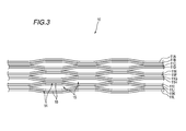
- FIG. 3 shows an example of the optical fiber ribbon fiber 10 accommodated inside the coating 30 of the optical fiber unit 1.
- the optical fiber ribbon 10 has a plurality of optical fiber cores arranged in parallel, and the connecting portion 14 in which adjacent optical fiber cores are connected and the adjacent optical fiber cores are connected.
- the non-connected portion 15 is an intermittent connection type optical fiber tape core wire provided intermittently in the longitudinal direction.
- FIG. 3 shows an intermittent connection type optical fiber ribbon in a state in which the optical fibers 11A to 11L are opened in the arrangement direction.
- the portion where the connecting portion 14 and the non-connecting portion 15 are intermittently provided may be between some of the optical fibers as shown in FIG. 3 or between all the optical fibers. It may be.
- the non-connecting portion 15 is not provided between the optical fiber cores 11A and 11B, 11C and 11D, 11E and 11F, 11G and 11H, 11I and 11J, and 11K and 11L.
- connection portion 14 in the optical fiber ribbon 10 is formed by applying a connection resin 16 made of, for example, an ultraviolet curable resin, a thermosetting resin, or the like between the optical fibers.
- a connection resin 16 made of, for example, an ultraviolet curable resin, a thermosetting resin, or the like between the optical fibers.
- the connecting resin 16 By applying the connecting resin 16 between predetermined optical fiber cores, the connecting part 14 and the non-connecting part 15 are intermittently provided, and the optical fiber cores 11A to 11L are integrated in parallel. Ru.
- the connection resin 16 may be applied to only one side of the parallel surface formed by the parallel optical fiber cores 11A to 11L, or may be applied to both sides.
- an optical fiber ribbon may be employed in which the non-connection portion 15 is not formed.
- the optical fiber ribbons 10 are connected to all the optical fiber ribbons 11A to 11L.
- the non-connection portion 15 may be formed by cutting a part with a rotary blade or the like.
- the optical fiber unit 1 configured as described above, a part of the circumferential direction is interrupted and the opening 31 is formed. Therefore, when the internal optical fiber core wire 11 is taken out, the covering is performed starting from the opening 31 It is possible to open 30. Moreover, when taking out the optical fiber core wire 11 inside, the optical fiber unit 1 is not tightened. Therefore, the optical fiber core wire 11 can be easily taken out from the opened opening 31 and can be taken out without damaging the optical fiber core wire 11.
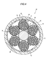
- FIG. 4 shows an example of the optical fiber cable in which the optical fiber unit 1 described above is accommodated.
- the optical fiber cable 40 includes a tension member 41 disposed at the center and a plurality (six in this example) of optical fiber units 1 (1A to 1) disposed around the tension member 41. 1F) and.
- the optical fiber cable 40 further includes a waterproof tape 42 covering the periphery of the optical fiber units 1A to 1F, and an outer sheath 43 covering the periphery of the waterproof tape 42.
- the jacket 43 is formed of a relatively hard material.
- the optical fiber units 1A to 1F of this example are disposed along the longitudinal direction around the tension member 41 without the optical fiber units being twisted together.
- the optical fiber units may be twisted together.
- the optical fiber units 1A to 1F are arranged around the tension member 41 with their outer shapes deformed.
- the optical fiber core wire 11 is used.
- the clamping force applied to 11 can be relaxed. Therefore, the optical fiber core wire 11 can be easily taken out without being damaged.
- FIG. 5 shows another example of the optical fiber cable in which the optical fiber unit 1 described above is accommodated.
- the optical fiber cable 50 has a plurality (five in this example) of optical fiber units 1 (1G to 1K) and an outer sheath 51 covering the circumference of the optical fiber units 1G to 1K. Is equipped.
- a tension member 52 is embedded in the inside of the jacket 51.
- the outer sheath 51 may be provided with a tear cord 53 for tearing the outer sheath 51 at the time of intermediate branching.
- a soft material is used for the outer cover 51 so as to be easily deformed.
- the optical fiber units 1 G to 1 K of this example are twisted together and accommodated inside the outer cover 51. For this reason, each of the optical fiber units 1G to 1K is accommodated in a state where its outer shape is deformed. According to the optical fiber cable 50 having such a configuration, the same effect as the optical fiber cable 40 can be obtained.
- optical fiber unit 10 optical fiber tape core wire 11 (11A to 11L): optical fiber core wire 14: connection portion 15: non-connection portion 16: connection resin 20: aggregate 30: coating 31: Opening 40, 50: Optical fiber cable 43, 51: Outer jacket
Landscapes
- Physics & Mathematics (AREA)
- General Physics & Mathematics (AREA)
- Optics & Photonics (AREA)
- Light Guides In General And Applications Therefor (AREA)
Abstract
L'invention concerne une unité de fibre optique comprenant : un ensemble constitué par le regroupement d'une pluralité de rubans de fibre optique, comprenant chacun une pluralité de fibres optiques disposées côte à côte ; et un couvercle qui recouvre la périphérie de l'ensemble dans un état dans lequel il y a un espace sur le côté interne du couvercle. Une partie du couvercle dans la direction circonférentielle de l'unité de fibre optique est discontinue, et une ouverture est formée dans le couvercle.
Priority Applications (3)
| Application Number | Priority Date | Filing Date | Title |
|---|---|---|---|
| JP2019550497A JP7192782B2 (ja) | 2017-11-02 | 2018-11-02 | 光ファイバユニットおよび光ファイバケーブル |
| EP18872603.8A EP3705924B1 (fr) | 2017-11-02 | 2018-11-02 | Unité de fibre optique et câble à fibre optique |
| US16/759,760 US11307370B2 (en) | 2017-11-02 | 2018-11-02 | Optical fiber unit and optical fiber cable |
Applications Claiming Priority (2)
| Application Number | Priority Date | Filing Date | Title |
|---|---|---|---|
| JP2017-212768 | 2017-11-02 | ||
| JP2017212768 | 2017-11-02 |
Publications (1)
| Publication Number | Publication Date |
|---|---|
| WO2019088255A1 true WO2019088255A1 (fr) | 2019-05-09 |
Family
ID=66332000
Family Applications (1)
| Application Number | Title | Priority Date | Filing Date |
|---|---|---|---|
| PCT/JP2018/040847 Ceased WO2019088255A1 (fr) | 2017-11-02 | 2018-11-02 | Unité de fibre optique et câble à fibre optique |
Country Status (4)
| Country | Link |
|---|---|
| US (1) | US11307370B2 (fr) |
| EP (1) | EP3705924B1 (fr) |
| JP (1) | JP7192782B2 (fr) |
| WO (1) | WO2019088255A1 (fr) |
Cited By (6)
| Publication number | Priority date | Publication date | Assignee | Title |
|---|---|---|---|---|
| JPWO2021049626A1 (fr) * | 2019-09-11 | 2021-03-18 | ||
| US20220373753A1 (en) * | 2020-03-27 | 2022-11-24 | Furukawa Electric Co., Ltd. | Optical Fiber Cable |
| EP4177652A4 (fr) * | 2020-07-01 | 2024-07-24 | Fujikura Ltd. | Câble optique et son procédé de fabrication |
| WO2024241470A1 (fr) * | 2023-05-23 | 2024-11-28 | 日本電信電話株式会社 | Câble à fibres optiques |
| WO2025146711A1 (fr) * | 2024-01-04 | 2025-07-10 | 住友電気工業株式会社 | Unité de fibre optique et câble à fibres optiques |
| JP2025541904A (ja) * | 2022-12-23 | 2025-12-23 | エルエス ケーブル アンド システム リミテッド. | 光ファイバーリボン |
Families Citing this family (1)
| Publication number | Priority date | Publication date | Assignee | Title |
|---|---|---|---|---|
| JP7192782B2 (ja) | 2017-11-02 | 2022-12-20 | 住友電気工業株式会社 | 光ファイバユニットおよび光ファイバケーブル |
Citations (12)
| Publication number | Priority date | Publication date | Assignee | Title |
|---|---|---|---|---|
| US20050013573A1 (en) | 2003-07-18 | 2005-01-20 | Lochkovic Gregory A. | Fiber optic articles, assemblies, and cables having optical waveguides |
| US20060193575A1 (en) | 2005-02-28 | 2006-08-31 | Greenwood Jody L | Loose tube fiber optic cables having at least one access location |
| JP2007010917A (ja) * | 2005-06-29 | 2007-01-18 | Sumitomo Electric Ind Ltd | 光ファイバユニット、光ファイバユニットの製造方法並びに光ファイバケーブル |
| US20070098339A1 (en) | 2002-12-19 | 2007-05-03 | Bringuier Anne G | Dry fiber optic cables and assemblies |
| JP2009271301A (ja) * | 2008-05-07 | 2009-11-19 | Advanced Cable Systems Corp | テープスロット型光ファイバケーブルおよび中間後分岐作業方法 |
| WO2010106858A1 (fr) | 2009-03-16 | 2010-09-23 | 株式会社フジクラ | Câble a fibres optiques |
| JP2010256793A (ja) * | 2009-04-28 | 2010-11-11 | Sumitomo Electric Ind Ltd | 光ケーブル |
| JP2011169939A (ja) | 2010-02-16 | 2011-09-01 | Furukawa Electric Co Ltd:The | 光ファイバユニット及び光ファイバケーブル |
| JP2014016529A (ja) * | 2012-07-10 | 2014-01-30 | Sumitomo Electric Ind Ltd | 光ファイバケーブル |
| JP2017212768A (ja) | 2016-05-23 | 2017-11-30 | 住友電装株式会社 | ワイヤーハーネス用結束部材、結束部材付ワイヤーハーネス |
| WO2019032332A1 (fr) | 2017-08-08 | 2019-02-14 | Corning Research & Development Corporation | Ruban de fibre optique enroulable à faible atténuation, fibre optique à grand diamètre de champ de mode et câble |
| EP3705924A1 (fr) | 2017-11-02 | 2020-09-09 | Sumitomo Electric Industries, Ltd. | Unité de fibre optique et câble à fibre optique |
Family Cites Families (45)
| Publication number | Priority date | Publication date | Assignee | Title |
|---|---|---|---|---|
| CH662231A5 (de) * | 1982-09-13 | 1987-09-15 | Eilentropp Hew Kabel | Flexibles elektrisches ablaengbares heiz- oder temperaturmesselement. |
| GB8605016D0 (en) * | 1986-02-28 | 1986-04-09 | Bicc Plc | Optical cable |
| DE3811126A1 (de) * | 1988-03-31 | 1989-10-12 | Siemens Ag | Optisches kabel mit mehreren buendelelementen |
| JPH087295B2 (ja) * | 1988-07-13 | 1996-01-29 | 住友電気工業株式会社 | 光分岐結合器の製造方法 |
| US5071221A (en) * | 1988-08-05 | 1991-12-10 | Mitsubishi Petrochemical Company Limited | Water penetration preventive cable |
| US5249249A (en) * | 1991-08-27 | 1993-09-28 | Siecor Corporation | Cable utilizing multiple light waveguide stacks |
| JP3320937B2 (ja) * | 1995-03-06 | 2002-09-03 | 住友電気工業株式会社 | 光ケーブル |
| JP4086978B2 (ja) * | 1998-09-17 | 2008-05-14 | 古河電気工業株式会社 | 光ファイバケーブル |
| KR100322123B1 (ko) * | 1998-11-18 | 2002-03-08 | 윤종용 | 스틸튜브를이용한광섬유복합가공지선 |
| US6561229B2 (en) * | 2000-06-26 | 2003-05-13 | Raymond L. Wellman | Electrostatic charge neutralizing fume duct with continuous carbon fiber |
| JP3578076B2 (ja) * | 2000-10-13 | 2004-10-20 | 住友電気工業株式会社 | 自己支持型ケーブル及びその製造方法 |
| US6828373B2 (en) * | 2001-03-07 | 2004-12-07 | Advanced Ceramics Research, Inc. | Water soluble tooling materials for composite structures |
| US6760523B2 (en) * | 2001-06-20 | 2004-07-06 | Alcatel | Tape based high fiber count cable |
| WO2003098307A1 (fr) * | 2002-05-17 | 2003-11-27 | Sumitomo Electric Industries, Ltd. | Coeur de fibre optique de type ruban, procede de production correspondant, connecteur portant un coeur de type ruban, ensemble de fibres optiques portant un coeur de type ruban et systeme de cablage optique |
| AU2003276713A1 (en) * | 2002-11-06 | 2004-06-07 | Sumitomo Electric Industries, Ltd. | Optical fiber ribbon and optical fiber cable using the same |
| US8152839B2 (en) * | 2005-12-19 | 2012-04-10 | Boston Scientific Scimed, Inc. | Embolic coils |
| JP4805010B2 (ja) | 2006-05-11 | 2011-11-02 | 古河電気工業株式会社 | 光ファイバケーブル |
| JP4943993B2 (ja) | 2007-10-31 | 2012-05-30 | パイオニア株式会社 | ナビゲーション装置、ナビゲーション方法、ナビゲーションプログラム、および記録媒体 |
| JP2009116017A (ja) | 2007-11-06 | 2009-05-28 | Sumitomo Electric Ind Ltd | 光ケーブル及び光ケーブルの製造方法 |
| CN102057309B (zh) * | 2008-06-30 | 2014-04-16 | 日本电信电话株式会社 | 光纤缆线以及光纤带 |
| JP5448699B2 (ja) | 2008-10-14 | 2014-03-19 | Sdpグローバル株式会社 | 吸収性樹脂粒子、この製造方法、これを含む吸収体及び吸収性物品 |
| JP2010243623A (ja) | 2009-04-02 | 2010-10-28 | Sumitomo Electric Ind Ltd | 光ケーブルの製造方法 |
| JP2010276632A (ja) | 2009-05-26 | 2010-12-09 | Sumitomo Electric Ind Ltd | 光ケーブルの製造方法 |
| JP5227996B2 (ja) * | 2010-04-05 | 2013-07-03 | 株式会社フジクラ | 光ファイバテープ心線、光ファイバケーブル及び配線形態 |
| JP2012128236A (ja) | 2010-12-16 | 2012-07-05 | Sumitomo Electric Ind Ltd | 光ケーブル |
| JP5272066B2 (ja) | 2011-03-23 | 2013-08-28 | 株式会社フジクラ | 光ファイバユニット、光ファイバユニットの製造方法、光ファイバユニットを用いた光ファイバーケーブル |
| JP2013025028A (ja) | 2011-07-20 | 2013-02-04 | Sumitomo Electric Ind Ltd | 光ケーブル |
| US9170388B2 (en) * | 2011-09-30 | 2015-10-27 | Corning Cable Systems Llc | Fiber optic ribbon cable having enhanced ribbon stack coupling and methods thereof |
| JP2013097320A (ja) | 2011-11-04 | 2013-05-20 | Fujikura Ltd | 光ファイバユニット、光ファイバケーブル、光ファイバユニットの製造方法及び光ファイバケーブルの製造方法 |
| JP5735399B2 (ja) | 2011-11-07 | 2015-06-17 | 株式会社フジクラ | 光ファイバケーブル及びその製造方法 |
| JP2013182094A (ja) | 2012-03-01 | 2013-09-12 | Sumitomo Electric Ind Ltd | 光ケーブル |
| JP5914057B2 (ja) | 2012-03-08 | 2016-05-11 | 株式会社フジクラ | 光ファイバユニットの作製方法及び光ファイバケーブルの製造方法 |
| JP5902007B2 (ja) | 2012-03-12 | 2016-04-13 | 株式会社フジクラ | 光ファイバケーブル及び光ファイバケーブルの製造方法 |
| JP2014119524A (ja) | 2012-12-14 | 2014-06-30 | Sumitomo Electric Ind Ltd | 光ケーブル |
| JP2014119635A (ja) | 2012-12-18 | 2014-06-30 | Sumitomo Electric Ind Ltd | 光ケーブル |
| JP6257156B2 (ja) | 2013-03-04 | 2018-01-10 | オリンパス株式会社 | 顕微鏡装置 |
| JP2014211511A (ja) * | 2013-04-18 | 2014-11-13 | 住友電気工業株式会社 | 光ケーブル |
| JP6268774B2 (ja) | 2013-07-10 | 2018-01-31 | 住友電気工業株式会社 | 光ケーブル |
| JP2015040990A (ja) | 2013-08-22 | 2015-03-02 | 住友電気工業株式会社 | 光ケーブル |
| JP6191343B2 (ja) | 2013-09-06 | 2017-09-06 | 住友電気工業株式会社 | 光ケーブル |
| JP6442161B2 (ja) | 2014-05-13 | 2018-12-19 | 株式会社フジクラ | 光ケーブル及び光ケーブルの製造方法 |
| JP2016061871A (ja) * | 2014-09-17 | 2016-04-25 | 古河電気工業株式会社 | 光ファイバケーブル |
| JP2017009924A (ja) | 2015-06-25 | 2017-01-12 | 古河電気工業株式会社 | 光ファイバユニット、光ファイバケーブル、および光ファイバユニットの製造方法 |
| JP2017037214A (ja) | 2015-08-11 | 2017-02-16 | 住友電気工業株式会社 | 光ケーブルおよびその製造方法 |
| CN108369324B (zh) * | 2015-12-01 | 2021-06-18 | 古河电气工业株式会社 | 光纤带芯线和光纤线缆 |
-
2018
- 2018-11-02 JP JP2019550497A patent/JP7192782B2/ja active Active
- 2018-11-02 EP EP18872603.8A patent/EP3705924B1/fr active Active
- 2018-11-02 WO PCT/JP2018/040847 patent/WO2019088255A1/fr not_active Ceased
- 2018-11-02 US US16/759,760 patent/US11307370B2/en active Active
Patent Citations (43)
| Publication number | Priority date | Publication date | Assignee | Title |
|---|---|---|---|---|
| US7471862B2 (en) | 2002-12-19 | 2008-12-30 | Corning Cable Systems, Llc | Dry fiber optic cables and assemblies |
| US20070098339A1 (en) | 2002-12-19 | 2007-05-03 | Bringuier Anne G | Dry fiber optic cables and assemblies |
| US20090074364A1 (en) | 2002-12-19 | 2009-03-19 | Bringuier Anne G | Dry Fiber Optic Cables and Assemblies |
| WO2005010565A2 (fr) | 2003-07-18 | 2005-02-03 | Corning Cable Systems Llc | Articles a fibres optiques, systemes et cables comprenant des guides d'onde optique |
| EP1646901A2 (fr) | 2003-07-18 | 2006-04-19 | Corning Cable Systems LLC | Articles a fibres optiques, systemes et cables comprenant des guides d'onde optique |
| US7050688B2 (en) | 2003-07-18 | 2006-05-23 | Corning Cable Systems Llc | Fiber optic articles, assemblies, and cables having optical waveguides |
| CN100498392C (zh) | 2003-07-18 | 2009-06-10 | 康宁光缆系统有限公司 | 具有光波导的光纤制品、组件及电缆 |
| CN1950736A (zh) | 2003-07-18 | 2007-04-18 | 康宁光缆系统有限公司 | 具有光波导的光纤制品、组件及电缆 |
| US20050013573A1 (en) | 2003-07-18 | 2005-01-20 | Lochkovic Gregory A. | Fiber optic articles, assemblies, and cables having optical waveguides |
| US20060193575A1 (en) | 2005-02-28 | 2006-08-31 | Greenwood Jody L | Loose tube fiber optic cables having at least one access location |
| US7203404B2 (en) | 2005-02-28 | 2007-04-10 | Corning Cable Systems, Llc. | Loose tube fiber optic cables having at least one access location |
| JP2007010917A (ja) * | 2005-06-29 | 2007-01-18 | Sumitomo Electric Ind Ltd | 光ファイバユニット、光ファイバユニットの製造方法並びに光ファイバケーブル |
| US9971101B2 (en) | 2005-07-29 | 2018-05-15 | Corning Optical Communications LLC | Fiber optic cable assembly |
| US20100290747A1 (en) | 2005-07-29 | 2010-11-18 | Bringuier Anne G | Dry Fiber Optic Cables and Assemblies |
| US20170031107A1 (en) | 2005-07-29 | 2017-02-02 | Corning Optical Communications LLC | Fiber optic cable assembly |
| US9494755B2 (en) | 2005-07-29 | 2016-11-15 | Corning Optical Communications LLC | Fiber optic cable assembly |
| US9482837B2 (en) | 2005-07-29 | 2016-11-01 | Corning Cable Systems Llc | Dry fiber optic cables and assemblies |
| US20090324183A1 (en) | 2005-07-29 | 2009-12-31 | Bringuier Anne G | Dry Fiber Optic Cables and Assemblies |
| US7787727B2 (en) | 2005-07-29 | 2010-08-31 | Corning Cable Systems Llc | Dry fiber optic cables and assemblies |
| US9477057B2 (en) | 2005-07-29 | 2016-10-25 | Corning Optical Communications LLC | Fiber optic cables and assemblies |
| US20140241678A1 (en) | 2005-07-29 | 2014-08-28 | Corning Optical Communications LLC | Fiber optic cable assembly |
| US20140212101A1 (en) | 2005-07-29 | 2014-07-31 | Corning Optical Communications LLC | Fiber optic cables and assemblies |
| WO2008076450A1 (fr) | 2006-12-21 | 2008-06-26 | Corning Cable Systems Llc | Câbles et ensembles de fibres optiques sèches |
| AU2007334346A1 (en) | 2006-12-21 | 2008-06-26 | Corning Cable Systems Llc | Dry fiber optic cables and assemblies |
| AU2007101252A4 (en) | 2006-12-21 | 2011-12-01 | Corning Cable Systems Llc | Dry fiber optic cables and assemblies |
| CN101529297A (zh) | 2006-12-21 | 2009-09-09 | 康宁光缆系统有限公司 | 干式光缆及组件 |
| EP2095164A1 (fr) | 2006-12-21 | 2009-09-02 | Corning Cable Systems LLC | Câbles et ensembles de fibres optiques sèches |
| JP2009271301A (ja) * | 2008-05-07 | 2009-11-19 | Advanced Cable Systems Corp | テープスロット型光ファイバケーブルおよび中間後分岐作業方法 |
| JP2010217392A (ja) | 2009-03-16 | 2010-09-30 | Fujikura Ltd | 光ファイバケーブル |
| WO2010106858A1 (fr) | 2009-03-16 | 2010-09-23 | 株式会社フジクラ | Câble a fibres optiques |
| TW201100890A (en) | 2009-03-16 | 2011-01-01 | Fujikura Ltd | Optical fiber cable |
| JP2010256793A (ja) * | 2009-04-28 | 2010-11-11 | Sumitomo Electric Ind Ltd | 光ケーブル |
| JP2011169939A (ja) | 2010-02-16 | 2011-09-01 | Furukawa Electric Co Ltd:The | 光ファイバユニット及び光ファイバケーブル |
| JP2014016529A (ja) * | 2012-07-10 | 2014-01-30 | Sumitomo Electric Ind Ltd | 光ファイバケーブル |
| JP2017212768A (ja) | 2016-05-23 | 2017-11-30 | 住友電装株式会社 | ワイヤーハーネス用結束部材、結束部材付ワイヤーハーネス |
| WO2019032332A1 (fr) | 2017-08-08 | 2019-02-14 | Corning Research & Development Corporation | Ruban de fibre optique enroulable à faible atténuation, fibre optique à grand diamètre de champ de mode et câble |
| US20190049681A1 (en) | 2017-08-08 | 2019-02-14 | Corning Research & Development Corporation | Rollable optical fiber ribbon with low attenuation, large mode field diameter optical fiber and cable |
| US10649163B2 (en) | 2017-08-08 | 2020-05-12 | Corning Research & Development Corporation | Rollable optical fiber ribbon with low attenuation, large mode field diameter optical fiber and cable |
| EP3665521A1 (fr) | 2017-08-08 | 2020-06-17 | Corning Research & Development Corporation | Ruban de fibre optique enroulable à faible atténuation, fibre optique à grand diamètre de champ de mode et câble |
| US20200249406A1 (en) | 2017-08-08 | 2020-08-06 | Corning Research & Development Corporation | Rollable optical fiber ribbon with low attenuation, large mode field diameter optical fiber and cable |
| US10948674B2 (en) | 2017-08-08 | 2021-03-16 | Corning Research & Development Corporation | Rollable optical fiber ribbon with low attenuation, large mode field diameter optical fiber and cable |
| US20210165178A1 (en) | 2017-08-08 | 2021-06-03 | Corning Research & Development Corporation | Rollable optical fiber ribbon with low attenuation, large mode field diameter optical fiber and cable |
| EP3705924A1 (fr) | 2017-11-02 | 2020-09-09 | Sumitomo Electric Industries, Ltd. | Unité de fibre optique et câble à fibre optique |
Non-Patent Citations (1)
| Title |
|---|
| See also references of EP3705924A4 |
Cited By (8)
| Publication number | Priority date | Publication date | Assignee | Title |
|---|---|---|---|---|
| JPWO2021049626A1 (fr) * | 2019-09-11 | 2021-03-18 | ||
| US20220373753A1 (en) * | 2020-03-27 | 2022-11-24 | Furukawa Electric Co., Ltd. | Optical Fiber Cable |
| US12292610B2 (en) * | 2020-03-27 | 2025-05-06 | Furukawa Electric Co., Ltd. | Optical fiber cable |
| EP4177652A4 (fr) * | 2020-07-01 | 2024-07-24 | Fujikura Ltd. | Câble optique et son procédé de fabrication |
| US12292613B2 (en) | 2020-07-01 | 2025-05-06 | Fujikura Ltd. | Optical cable and optical-cable manufacturing method |
| JP2025541904A (ja) * | 2022-12-23 | 2025-12-23 | エルエス ケーブル アンド システム リミテッド. | 光ファイバーリボン |
| WO2024241470A1 (fr) * | 2023-05-23 | 2024-11-28 | 日本電信電話株式会社 | Câble à fibres optiques |
| WO2025146711A1 (fr) * | 2024-01-04 | 2025-07-10 | 住友電気工業株式会社 | Unité de fibre optique et câble à fibres optiques |
Also Published As
| Publication number | Publication date |
|---|---|
| JP7192782B2 (ja) | 2022-12-20 |
| EP3705924A4 (fr) | 2021-08-04 |
| US11307370B2 (en) | 2022-04-19 |
| US20210181440A1 (en) | 2021-06-17 |
| JPWO2019088255A1 (ja) | 2020-11-12 |
| EP3705924B1 (fr) | 2022-10-19 |
| EP3705924A1 (fr) | 2020-09-09 |
Similar Documents
| Publication | Publication Date | Title |
|---|---|---|
| JP7192782B2 (ja) | 光ファイバユニットおよび光ファイバケーブル | |
| US10268015B2 (en) | Optical fiber cable having a plurality of stranded optical fiber ribbons | |
| JP6674893B2 (ja) | 外装材付き光ファイバケーブル | |
| ES2914224T3 (es) | Tubo suelto, cable de fibra óptica de tipo tubo suelto, método de aislamiento de fibra única para cinta de fibra óptica de tubo suelto, método de fabricación de tubo suelto y método para reunir una pluralidad de fibras ópticas | |
| JP5272066B2 (ja) | 光ファイバユニット、光ファイバユニットの製造方法、光ファイバユニットを用いた光ファイバーケーブル | |
| WO2011059065A1 (fr) | Câble de fibres optiques et procédé de fabrication de celui-ci | |
| JP2014119635A (ja) | 光ケーブル | |
| WO2020145129A1 (fr) | Câble de fibre optique et procédé de production de noyau de câble | |
| WO2022092019A1 (fr) | Câble à fibres optiques et câble avec connecteur | |
| WO2019088256A1 (fr) | Unité à fibres optiques et câble à fibres optiques | |
| JP7151727B2 (ja) | 光ファイバケーブル | |
| JP7200947B2 (ja) | 光ファイバケーブルおよび光ファイバケーブルの製造方法 | |
| KR20200106570A (ko) | 광섬유 유닛 및 광섬유 케이블 | |
| US11435543B2 (en) | Optical fiber unit and optical fiber cable | |
| JP5568071B2 (ja) | 光ファイバケーブル | |
| JP6413593B2 (ja) | 光ファイバケーブル | |
| JP2019056837A (ja) | 光ファイバケーブル | |
| JP2014228821A (ja) | 光ファイバケーブル | |
| JP2007148181A (ja) | 光ファイバケーブル | |
| JP2014119524A (ja) | 光ケーブル | |
| JP2004212960A (ja) | 光ファイバケーブル | |
| JP2012173398A (ja) | 光ケーブル | |
| JP2010128169A (ja) | 光ファイバケーブル | |
| JP2004144960A (ja) | 光ファイバケーブル | |
| JP2018132541A (ja) | 光ファイバケーブル |
Legal Events
| Date | Code | Title | Description |
|---|---|---|---|
| 121 | Ep: the epo has been informed by wipo that ep was designated in this application |
Ref document number: 18872603 Country of ref document: EP Kind code of ref document: A1 |
|
| ENP | Entry into the national phase |
Ref document number: 2019550497 Country of ref document: JP Kind code of ref document: A |
|
| NENP | Non-entry into the national phase |
Ref country code: DE |
|
| ENP | Entry into the national phase |
Ref document number: 2018872603 Country of ref document: EP Effective date: 20200602 |