WO2019088755A1 - Moteur - Google Patents
Moteur Download PDFInfo
- Publication number
- WO2019088755A1 WO2019088755A1 PCT/KR2018/013248 KR2018013248W WO2019088755A1 WO 2019088755 A1 WO2019088755 A1 WO 2019088755A1 KR 2018013248 W KR2018013248 W KR 2018013248W WO 2019088755 A1 WO2019088755 A1 WO 2019088755A1
- Authority
- WO
- WIPO (PCT)
- Prior art keywords
- disposed
- substrate
- cap member
- rotor
- wire
- Prior art date
- Legal status (The legal status is an assumption and is not a legal conclusion. Google has not performed a legal analysis and makes no representation as to the accuracy of the status listed.)
- Ceased
Links
Images


Classifications
-
- H—ELECTRICITY
- H02—GENERATION; CONVERSION OR DISTRIBUTION OF ELECTRIC POWER
- H02K—DYNAMO-ELECTRIC MACHINES
- H02K11/00—Structural association of dynamo-electric machines with electric components or with devices for shielding, monitoring or protection
- H02K11/01—Structural association of dynamo-electric machines with electric components or with devices for shielding, monitoring or protection for shielding from electromagnetic fields, i.e. structural association with shields
- H02K11/014—Shields associated with stationary parts, e.g. stator cores
- H02K11/0141—Shields associated with casings, enclosures or brackets
-
- H—ELECTRICITY
- H02—GENERATION; CONVERSION OR DISTRIBUTION OF ELECTRIC POWER
- H02K—DYNAMO-ELECTRIC MACHINES
- H02K11/00—Structural association of dynamo-electric machines with electric components or with devices for shielding, monitoring or protection
- H02K11/02—Structural association of dynamo-electric machines with electric components or with devices for shielding, monitoring or protection for suppression of electromagnetic interference
-
- H—ELECTRICITY
- H02—GENERATION; CONVERSION OR DISTRIBUTION OF ELECTRIC POWER
- H02K—DYNAMO-ELECTRIC MACHINES
- H02K11/00—Structural association of dynamo-electric machines with electric components or with devices for shielding, monitoring or protection
- H02K11/20—Structural association of dynamo-electric machines with electric components or with devices for shielding, monitoring or protection for measuring, monitoring, testing, protecting or switching
- H02K11/21—Devices for sensing speed or position, or actuated thereby
- H02K11/215—Magnetic effect devices, e.g. Hall-effect or magneto-resistive elements
-
- H—ELECTRICITY
- H02—GENERATION; CONVERSION OR DISTRIBUTION OF ELECTRIC POWER
- H02K—DYNAMO-ELECTRIC MACHINES
- H02K11/00—Structural association of dynamo-electric machines with electric components or with devices for shielding, monitoring or protection
- H02K11/20—Structural association of dynamo-electric machines with electric components or with devices for shielding, monitoring or protection for measuring, monitoring, testing, protecting or switching
- H02K11/25—Devices for sensing temperature, or actuated thereby
-
- H—ELECTRICITY
- H02—GENERATION; CONVERSION OR DISTRIBUTION OF ELECTRIC POWER
- H02K—DYNAMO-ELECTRIC MACHINES
- H02K5/00—Casings; Enclosures; Supports
- H02K5/04—Casings or enclosures characterised by the shape, form or construction thereof
- H02K5/22—Auxiliary parts of casings not covered by groups H02K5/06-H02K5/20, e.g. shaped to form connection boxes or terminal boxes
- H02K5/225—Terminal boxes or connection arrangements
-
- G—PHYSICS
- G01—MEASURING; TESTING
- G01D—MEASURING NOT SPECIALLY ADAPTED FOR A SPECIFIC VARIABLE; ARRANGEMENTS FOR MEASURING TWO OR MORE VARIABLES NOT COVERED IN A SINGLE OTHER SUBCLASS; TARIFF METERING APPARATUS; MEASURING OR TESTING NOT OTHERWISE PROVIDED FOR
- G01D5/00—Mechanical means for transferring the output of a sensing member; Means for converting the output of a sensing member to another variable where the form or nature of the sensing member does not constrain the means for converting; Transducers not specially adapted for a specific variable
- G01D5/12—Mechanical means for transferring the output of a sensing member; Means for converting the output of a sensing member to another variable where the form or nature of the sensing member does not constrain the means for converting; Transducers not specially adapted for a specific variable using electric or magnetic means
- G01D5/14—Mechanical means for transferring the output of a sensing member; Means for converting the output of a sensing member to another variable where the form or nature of the sensing member does not constrain the means for converting; Transducers not specially adapted for a specific variable using electric or magnetic means influencing the magnitude of a current or voltage
- G01D5/142—Mechanical means for transferring the output of a sensing member; Means for converting the output of a sensing member to another variable where the form or nature of the sensing member does not constrain the means for converting; Transducers not specially adapted for a specific variable using electric or magnetic means influencing the magnitude of a current or voltage using Hall-effect devices
- G01D5/145—Mechanical means for transferring the output of a sensing member; Means for converting the output of a sensing member to another variable where the form or nature of the sensing member does not constrain the means for converting; Transducers not specially adapted for a specific variable using electric or magnetic means influencing the magnitude of a current or voltage using Hall-effect devices influenced by the relative movement between the Hall device and magnetic fields
-
- H—ELECTRICITY
- H02—GENERATION; CONVERSION OR DISTRIBUTION OF ELECTRIC POWER
- H02K—DYNAMO-ELECTRIC MACHINES
- H02K2203/00—Specific aspects not provided for in the other groups of this subclass relating to the windings
- H02K2203/09—Machines characterised by wiring elements other than wires, e.g. bus rings, for connecting the winding terminations
-
- H—ELECTRICITY
- H02—GENERATION; CONVERSION OR DISTRIBUTION OF ELECTRIC POWER
- H02K—DYNAMO-ELECTRIC MACHINES
- H02K2211/00—Specific aspects not provided for in the other groups of this subclass relating to measuring or protective devices or electric components
- H02K2211/03—Machines characterised by circuit boards, e.g. pcb
Definitions
- An embodiment relates to a motor.
- the motor includes a rotor and a stator.
- the coil is wound on the stator.
- the motor is required to be small in size and high in output. However, when the output of the motor is increased, the internal temperature of the motor is increased. Therefore, understanding the temperature inside the motor is a very important problem in ensuring the performance of the motor.
- An apparatus for sensing the position of a rotor comprising a sensing magnet and a sensor.
- the sensing magnet is coupled to the shaft and is interlocked with the rotation of the shaft.
- the sensor is placed facing the sensing magnet. The sensor senses the magnetic force of the sensing magnet.
- Accurate sensing of rotor position is a very important factor in controlling the motor.
- the performance of detecting the position of the rotor due to electromagnetic waves or noise generated inside or outside of the motor can be greatly deteriorated.
- a cap member for shielding electromagnetic waves and noise is provided around the sensing magnet and the sensor.
- the number of parts due to the installation of the cap member increases, the installation process of the cap member is added, complicating the assembling process, and it is difficult to secure the space for installing the cap member.
- an embodiment of the present invention is directed to a motor that can prevent an error in temperature measurement by a temperature sensor, increase the fixing force of the temperature sensor, and simplify the process.
- the embodiment also aims to provide a motor that can simplify the structure of the cap member, reduce the number of assembling steps, and easily secure a space for installing the cap member.
- An embodiment of the present invention is directed to a stator comprising: a shaft; a rotor disposed outside the shaft; a stator disposed outside the rotor; a bus bar disposed on the stator; and a cover disposed on the busbar,
- a bar includes a terminal connected to the coil of the stator and an insulator insulating the terminal, and the cover includes a power terminal portion coupled to the terminal, a temperature sensor connected to the power terminal portion, and a pad portion connected to the temperature sensor
- the motor can be provided.
- a front flange disposed between the bus bar and the cover may be further included.
- the front flange may further include a rear flange disposed on an upper side of the housing and disposed on a lower side of the housing.
- the temperature sensor includes a head portion and a wire connected to the head portion, and the pad portion may include a connection end connected to the wire.
- the wire includes a first wire and a second wire
- the pad portion includes a first pad portion and a second pad portion
- the first wire is connected to the first pad portion
- the wire may be connected to the second pad portion.
- the power terminal portion includes a plurality of terminals, and a first one of the plurality of terminals may be connected to the temperature sensor.
- the front flange includes a hole formed to correspond to a position of a terminal of the bus bar, and a terminal of the bus bar can be coupled with the plurality of terminals through the hole.
- one end of the first terminal of the power terminal portion is coupled to the terminal, and the other end of the power terminal portion may be formed with a mounting groove that engages with the head portion of the temperature sensor.
- the mounting groove may be concave at the end of the first terminal corresponding to the shape of the head portion.
- the base cover may include a receiving portion disposed on a lower surface of the lower surface of the cover, and a wall protruding from the receiving portion and disposed between the wire and the wire.
- the cover includes a hole disposed on an upper surface of the cover, and the hole may expose a part of the pad portion.
- An embodiment of the present invention is directed to a rotor including a shaft, a rotor disposed outside the shaft, a stator disposed outside the rotor, a sensing magnet coupled to the rotor, and a rotor disposed on the sensing magnet, And a cap member covering the sensor, wherein the circuit board includes a first substrate, a second substrate spaced apart from the first substrate, and a second substrate spaced apart from the first substrate, And a connecting portion connecting the second substrate, wherein the sensor is mounted on the second substrate, and the swinging cap member is arranged to penetrate the spacing space between the first substrate and the second substrate have.
- the first substrate includes a through-hole
- the second substrate may be disposed inside the through-hole
- the fixing unit further includes a fixing unit fixing the cap member to the substrate, wherein the fixing unit includes a body portion contacting the upper surface of the cap member, and a leg portion disposed at both ends of the body and coupled to the substrate can do.
- the leg portion is bent in the body portion, and the latch portion may be disposed at the end portion.
- the cap member is provided with a slot disposed upward at a lower end of the cap member, and the connection portion may be disposed in the slot.
- the first substrate includes a groove recessed inwardly of the first substrate in the through hole, and the leg may be disposed in the groove.
- the apparatus further includes a cover including a housing disposed above the rotor and the stator, the cover covering an upper portion of the housing, wherein the substrate is disposed on the upper side of the cover, .
- the lower end of the cap member is disposed above the cover and below the upper end of the shaft.
- the temperature sensor for measuring the internal temperature of the motor provides a favorable effect of high fixing power.
- the temperature sensor it is possible to prevent the temperature sensor from being detached, thereby providing an advantageous effect of preventing errors in the temperature measurement.
- the process provides a simple beneficial effect.
- an advantageous effect of simplifying the assembling process of the cap member is provided.
- FIG. 1 is a cross-sectional view of a motor according to an embodiment
- Fig. 2 is an exploded view of the motor shown in Fig. 1,
- FIG. 5 is a view showing a power supply terminal portion, a temperature sensor, and a pad portion
- FIG. 6 is a view showing a process of connecting the head part of the temperature sensor to the connection end of the terminal
- FIG. 7 is a view showing a process of connecting the wire of the temperature sensor to the pad portion
- FIG. 8 is a view showing a temperature sensor connected to the power supply terminal portion and the pad portion
- FIG. 10 is a view showing a circuit board, a cap member and a fixing portion
- FIG. 12 is a view showing a cap member mounted on a circuit board
- FIG. 13 is a view showing a fixing part coupled to a circuit board
- the singular form may include plural forms unless otherwise specified in the text, and may be a combination of A, B, and C when described as " A and / or at least one (or more than one) Or < / RTI > all possible combinations.
- first, second, A, B, (a), and (b) may be used.
- the expression “upward” or “downward” may include not only an upward direction but also a downward direction on the basis of one component.
- Fig. 1 is a sectional view showing a motor according to an embodiment
- Fig. 2 is an exploded view of the motor shown in Fig.
- the motor according to the embodiment may include a shaft 100, a rotor 200, a stator 300, a bus bar 400, and a housing 500 .
- the shaft 100 may be coupled to the rotor 200.
- the rotor 200 rotates and the shaft 100 rotates in conjunction therewith.
- the rotor (200) rotates through electrical interaction with the stator (300).
- the rotor 200 may include a rotor core and a magnet.
- the rotor core may be embodied in a laminated shape of a plurality of plates in the form of a circular thin steel plate or in the form of a single barrel.
- a hole to which the shaft 100 is coupled may be formed at the center of the rotor core.
- the magnet may be attached to the outer circumferential surface of the rotor core.
- the plurality of magnets may be disposed along the circumference of the rotor core at regular intervals. Or one ring-shaped magnet may be attached to the rotor core.
- the coil may be wound to induce electrical interaction with the rotor 200 in the stator 300.
- the specific configuration of the stator 300 for winding the coil is as follows.
- the stator 300 may include a stator core including a plurality of teeth.
- the stator core is provided with an annular yoke portion, and a tooth wound around the yoke in the center direction may be provided.
- the teeth may be provided at regular intervals along the outer circumferential surface of the yoke portion.
- the stator core may be formed by laminating a plurality of plates in the form of a thin steel plate. Further, the stator core may be formed by connecting or connecting a plurality of divided cores.
- the bus bar 400 may be disposed on the stator 300. And a body 420 that insulates the terminal 410 from the terminal 410.
- the body 420 may be annular.
- the terminal 410 may include a neutral terminal for electrically connecting the phase terminal with the phase terminal connected to the power sources of the U, V, and W phases.
- the housing 500 may be disposed outside the rotor 200 and the stator 300.
- the housing 500 may be a cylindrical member having upper and lower openings.
- the housing 500 forms a space for accommodating the rotor 200 and the stator 300 on the inner side.
- the front flange 600 may be disposed on the upper side of the stator 300.
- a bearing 610 may be disposed at the center of the front flange 600.
- the front flange 600 may be provided with a hole 620 through which the terminal 410 passes. The front flange 600 is engaged with the upper portion of the housing 500 to cover the upper portion of the opened housing 500.
- the rear cover 700 may be disposed on the lower side of the stator 300. A hole may be disposed at the center of the rear cover 700. The rear cover 700 is engaged with the lower portion of the housing 500 to cover the lower portion of the opened housing 500.
- the sensing magnet 800 may be coupled to an end of the rotary shaft 100.
- the sensing magnet 800 is a device for detecting the position of the rotor 200.
- the cover 900 may be disposed on the upper side of the front flange 600.
- the cover 900 may be seated on the front flange 600.
- the cover 900 and the front flange 600 can be fastened to each other through a fastening structure extending from the cover 900 or a separate fastening member.
- a sensor 1010 for sensing the magnetic force of the sensing magnet 800 may be disposed on the circuit board 1000. At this time, the sensor 1010 may be a Hall IC. The sensor 1010 senses changes in the N and S poles of the sensing magnet 800 and generates a sensing signal.
- Fig. 3 is a top view of the cover
- Fig. 4 is a bottom view of the cover.
- the cover 900 may include a power supply terminal portion 910, a temperature sensor 920, and a pad portion 930.
- the cover 900 may include a cover body 901.
- the cover body 901 may be in the form of a disc.
- a hole 901a may be disposed in the center of the cover body 901.
- a locking boss 901b may protrude from the upper surface of the cover body 901.
- the coupling boss 901b is for coupling with the circuit board 1000.
- the power terminal portion 910 electrically connects the external power source and the coil wound around the stator 300.
- FIG. 5 is a view showing a power supply terminal portion, a temperature sensor, and a pad portion.
- the power supply terminal portion 910 includes a plurality of terminals 911, 912, and 913.
- the terminals 911, 912, and 913 may be connected to the power sources of U, V, and W, respectively.
- the connection terminal 912a may be extended to the first terminal 912, which is one of the plurality of terminals 911, 912, and 913.
- a temperature sensor 920 is electrically connected to the connection terminal 912a.
- the temperature sensor 920 may include a head portion 921 and a wire 922.
- the head portion 921 may be an electronic device whose resistance value changes with a change in temperature.
- the head portion 921 is manganese. cobalt. Nickel, or the like.
- the head portion 921 may be rounded round.
- the wire 922 is electrically connected to the head portion 921.
- the head portion 921 is connected to the connection end 912a.
- the wire 922 is electrically connected to the pad portion 930.
- the wire 922 may include a first wire 922a and a second wire 922b.
- the pad portion 930 is electrically connected to the wire 922.
- the pad unit 930 may be connected to an electronic control unit of the vehicle.
- the pad portion 930 includes a first pad portion 931 and a second pad portion 931. And may include a second pad portion 932.
- the first pad portion 931 is connected to the first wire 922a.
- the second pad portion 932 is connected to the second wire 922b.
- the power terminal portion 910 and the pad portion 930 are disposed apart from the cover body 901 and the power source terminal portion 910 connects the pad portion 930 with the temperature sensor 920.
- a terminal of the plurality of terminals 911, 912, and 913 of the power terminal 910 may be a first terminal 912 disposed closest to the pad 930.
- a receiving portion 901c accommodating the temperature sensor 920 may be disposed on the lower surface of the cover body 901.
- the connection terminal 912a of the first terminal 912 and the connection terminals 931a and 932a of the pad portion 930 may be exposed in the receiving portion 901c.
- a wall 901d may protrude from the receiving portion 901c.
- the wall 901d is disposed between the first wire 922a and the second wire 922b and serves to partition the receiving space of the first wire 922a and the receiving space of the second wire 922b.
- the heat generated in the coil of the stator 300 is transmitted to the connection terminal 912a of the power supply terminal portion 910 and the heat transmitted to the connection terminal 912a is transmitted to the head portion 921.
- the resistance value of the head portion 921 is changed and the converted resistance value is transmitted to the wire 922 and the pad portion 930.
- the resistance value of the head portion 921 is transmitted to the wire portion 922 through the pad portion 930,
- the electronic control unit of the vehicle converts the changed resistance value of the head unit 921 to detect the temperature inside the motor. Temperature data inside the motor corresponding to the changed resistance value of the head portion 921 can be stored in advance in the electronic control unit of the vehicle.
- FIG. 6 is a view showing a process of connecting the head part of the temperature sensor to the connection end of the terminal.
- connection end 912a of the first terminal 912 is arranged to be exposed in the accommodating portion 901c.
- a round mounting groove 912aa may be disposed corresponding to the shape of the head portion 921.
- FIG. 7 is a view showing a process of connecting the wire of the temperature sensor to the pad portion.
- the wires 922 are fixed to the connection ends 931a and 932a of the pad portion 930 through soldering 903 as shown in Figs. 7A and 7B.
- FIG. 8 is a view showing a temperature sensor connected to the power supply terminal portion and the pad portion.
- the head portion 921 of the temperature sensor 920 is connected to the power source terminal portion 910.
- the wire 922 of the temperature sensor 920 is connected to the pad portion 930.
- FIG. 9 is a view showing a connector of a pad portion.
- a connector 901e for exposing the connection ends 931b and 932b of the pad portion 930 may be disposed on the upper surface of the cover body 901.
- the connector 901e is disposed concave on the upper surface of the cover body 901.
- the connector 901e may include two holes 901f for exposing the connection terminals 931b and 932b of the pad portion 930, respectively.
- An external connector connected to the electronic control unit of the vehicle may be inserted into the connector 901e.
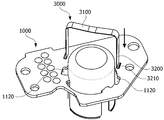
- FIG. 10 is a view showing a circuit board, a cap member, and a fixing portion.
- the cap member 2000 is disposed through the circuit board 1000, and the fixing portion 3000 presses the cap member 2000 to fix the cap member 2000 to the circuit board 1000.
- the upper part of the cap member 2000 protrudes from the upper surface of the circuit board 1000 and the lower part of the cap member 2000 protrudes downward from the lower surface of the circuit board 1000.
- the circuit board 1000 may include a first substrate 1100, a second substrate 1200, and a connection portion 1300.
- the first substrate 1100 includes a through hole 1110.
- the second substrate 1200 is disposed inside the through-hole 1110.
- the second substrate 1200 may be in the form of a disc.
- the first substrate 1100 and the second substrate 1200 are spaced apart from each other and connected to each other through a connection portion 1300.
- the connection portion 1300 may be plural.
- the connection portions 1300 may be disposed at regular intervals along the through holes 1110.
- the overall shape of the circuit board 1000 is such that the second substrate 1200 is disposed on the inner side with respect to the through hole 1110 and the first substrate 1100 is disposed on the outer side.
- the first substrate 1100 may include a groove 1120.
- the groove 1120 is concave toward the first substrate 1100 in the through hole 1110.
- the fixing portion 3000 is inserted into the groove 1120.
- the grooves 1120 may be two and the two grooves 1120 may be disposed symmetrically with respect to the center of the second substrate 1200.
- the first substrate 1100 may be coupled to the cover 900.
- the first substrate 1100 may include a fastening hole 1130.
- the number of the fastening holes 1130 may be plural.
- the fastening hole 1130 is a fastening structure extending from the cover 900 or a place where a separate fastening member joins.
- the fastening holes 1130 can be aligned with the fastening bosses 901b of the cover 900.
- FIG. 12 is a view showing a cap member mounted on a circuit board.
- the cap member 2000 may be mounted on the circuit board 1000 through the circuit board 1000 from the upper side to the lower side of the circuit board 1000.
- the upper part of the cap member 2000 is clogged with the upper surface, and the lower part of the cap member 2000 may be an open cylindrical member.
- a slot 2100 may be disposed on a side surface of the cap member 2000.
- the slot 2100 may be disposed long from the lower end of the cap member 2000 toward the upper end.
- the connection portion 1300 is inserted into the slot 2100. When the cap member 2000 is mounted through the circuit board 1000, the connection portion 1300 moves along the slot 2100. [
- the number of slots 2100 is the same as the number of connection portions 1300.
- FIG. 13 is a view showing a fixing portion to be coupled to a circuit board.
- the cap member 2000 is disposed through the circuit board 1000 until the upper end of the slot 2100 is caught by the connection portion 1300.
- the fixing portion 3000 can be coupled to the circuit board 1000 on the upper side of the cap member 2000 with the cap member 2000 mounted on the circuit board 1000.
- the fixing part 3000 may include a body part 3100 and a leg part 3200.
- the fixing part 3000 may be a strip-like member.
- the body portion 3100 is in contact with the upper surface of the cap member 2000.
- the body portion 3100 elastically presses the upper surface of the cap member 2000 to fix the cap member 2000 to the circuit board 1000.
- the leg portion 3200 is inserted into the groove 1120.
- a hook-shaped latching portion 3210 may be disposed at the lower end of the leg portion 3200.
- FIG. 14 is a side cross-sectional view in a state where the circuit board, the cap member, and the fixing portion are engaged.
- the circuit board 1000 is disposed on the upper side of the sensing magnet 800.
- a sensor 1010 is disposed on the lower surface of the second substrate 1200 of the circuit board 1000.
- the sensor 1010 is arranged facing the sensing magnet 800.
- the upper part of the cap member 2000 refers to a part of the cap member 2000 located on the upper side of the circuit board 1000 when the cap member 2000 is fixed to the circuit board 1000.
- the lower part of the cap member 2000 shows a part of the cap member 2000 positioned below the circuit board 1000 when the cap member 2000 is fixed to the circuit board 1000.
- the upper portion of the cap member 2000 surrounds the upper space of the second substrate 1200.
- the lower portion of the cap member 2000 surrounds the lower space of the second substrate 1200 on which the sensor 1010 is mounted. Since the upper space of the second substrate 1200 is covered with the upper portion of the cap member 2000, electromagnetic waves on the sensor 1010 can be shielded from the upper side of the second substrate 1200. Since the lower space of the second substrate 1200 is surrounded by the lower portion of the cap member 2000, electromagnetic waves on the sensor 1010 can be shielded from the lower side of the second substrate 1200.
- the lower end of the cap member 2000 is positioned so that the position H2 of the lower end of the cap member 2000 is lower than the position H1 of the upper end of the shaft 100 in a state in which the connection portion 1300 is engaged with the upper end of the slot 2100
- the length of the lower portion is determined. This is a structure for maximally shielding the electromagnetic waves from the sensing magnet 800 disposed at the upper end of the shaft 100 and the sensor 1010 disposed above the sensing magnet 800.
- the latching portion 3210 of the leg portion 3200 inserted into the groove 1120 is caught by the lower surface of the first substrate 1100 and fixed so that the fixing portion 3000 is not detached from the circuit board 1000.
Landscapes
- Engineering & Computer Science (AREA)
- Power Engineering (AREA)
- Microelectronics & Electronic Packaging (AREA)
- Physics & Mathematics (AREA)
- Electromagnetism (AREA)
- Motor Or Generator Frames (AREA)
Abstract
La présente invention concerne un moteur qui comprend : un arbre ; un rotor qui est disposé sur l'extérieur de l'arbre ; un stator qui est disposé sur l'extérieur du rotor ; un aimant de détection qui est couplé au rotor ; une carte de circuit imprimé qui est disposée au-dessus de l'aimant de détection et qui comprend un capteur permettant de détecter des changements de flux magnétique provoqués par l'aimant de détection ; et un élément chapeau permettant de recouvrir le capteur, ladite carte de circuit imprimé comprenant une première carte, une seconde carte qui est séparée de la première carte, et une section de liaison qui relie la première carte et la seconde carte, ledit capteur étant monté sur la seconde carte, et ledit élément chapeau passant par l'espace de séparation entre la première carte et la seconde carte.
Priority Applications (4)
| Application Number | Priority Date | Filing Date | Title |
|---|---|---|---|
| US16/760,339 US11527940B2 (en) | 2017-11-02 | 2018-11-02 | Motor |
| JP2020524381A JP7271537B2 (ja) | 2017-11-02 | 2018-11-02 | モーター |
| CN201880071689.3A CN111316542B (zh) | 2017-11-02 | 2018-11-02 | 马达 |
| EP18872908.1A EP3706293B1 (fr) | 2017-11-02 | 2018-11-02 | Moteur |
Applications Claiming Priority (4)
| Application Number | Priority Date | Filing Date | Title |
|---|---|---|---|
| KR1020170145510A KR102493905B1 (ko) | 2017-11-02 | 2017-11-02 | 모터 |
| KR10-2017-0145511 | 2017-11-02 | ||
| KR1020170145511A KR102493906B1 (ko) | 2017-11-02 | 2017-11-02 | 모터 |
| KR10-2017-0145510 | 2017-11-02 |
Publications (1)
| Publication Number | Publication Date |
|---|---|
| WO2019088755A1 true WO2019088755A1 (fr) | 2019-05-09 |
Family
ID=66332644
Family Applications (1)
| Application Number | Title | Priority Date | Filing Date |
|---|---|---|---|
| PCT/KR2018/013248 Ceased WO2019088755A1 (fr) | 2017-11-02 | 2018-11-02 | Moteur |
Country Status (5)
| Country | Link |
|---|---|
| US (1) | US11527940B2 (fr) |
| EP (1) | EP3706293B1 (fr) |
| JP (1) | JP7271537B2 (fr) |
| CN (1) | CN111316542B (fr) |
| WO (1) | WO2019088755A1 (fr) |
Cited By (1)
| Publication number | Priority date | Publication date | Assignee | Title |
|---|---|---|---|---|
| WO2021122954A1 (fr) * | 2019-12-20 | 2021-06-24 | Valeo Equipements Electriques Moteur | Machine électrique tournante avec un capteur de température |
Families Citing this family (5)
| Publication number | Priority date | Publication date | Assignee | Title |
|---|---|---|---|---|
| US12313049B2 (en) * | 2020-01-09 | 2025-05-27 | Lg Innotek Co., Ltd. | Motor and position sensing arrangement |
| FR3113425B1 (fr) * | 2020-08-14 | 2022-07-22 | Bontaz Centre R & D | Distributeur fluidique a fonctionnement ameliore |
| CN115149742A (zh) * | 2021-03-31 | 2022-10-04 | 日本电产株式会社 | 马达和电气产品 |
| DE102023124309A1 (de) * | 2023-09-08 | 2025-03-13 | Dr. Fritz Faulhaber GmbH & Co.KG | Motoranordnung, Elektromotor und Bausatz für eine Motoranordnung |
| DE102024200965A1 (de) * | 2024-02-02 | 2025-08-07 | Zf Friedrichshafen Ag | Motoranordnung für ein Fahrrad |
Citations (5)
| Publication number | Priority date | Publication date | Assignee | Title |
|---|---|---|---|---|
| KR19990042651A (ko) * | 1997-11-27 | 1999-06-15 | 윤종용 | 모터 회전수 감지장치 |
| US6078117A (en) * | 1997-08-27 | 2000-06-20 | Nartron Corporation | End cap assembly and electrical motor utilizing same |
| DE19936218A1 (de) * | 1999-08-04 | 2001-02-15 | Sew Eurodrive Gmbh & Co | Verfahren zur sicheren elektrischen Trennung und einen temperaturempfindlichen Sensor |
| US20150379897A1 (en) * | 2014-06-30 | 2015-12-31 | Robert Bosch Gmbh | Electric Motor Construction Kit and Electric Motor |
| US20160013697A1 (en) * | 2014-07-14 | 2016-01-14 | Nidec Corporation | Motor |
Family Cites Families (16)
| Publication number | Priority date | Publication date | Assignee | Title |
|---|---|---|---|---|
| US4152671A (en) * | 1977-07-25 | 1979-05-01 | Atari, Inc. | Oscillator-modulator apparatus and method therefor |
| US4214360A (en) * | 1978-10-10 | 1980-07-29 | Atari, Inc. | Method of making a radio frequency oscillator-modulator with ground metallization |
| FR2652227B1 (fr) * | 1989-09-19 | 1996-08-02 | Legrand Sa | Carte de circuit imprime avec capot de blindage. |
| US5005283A (en) * | 1990-09-19 | 1991-04-09 | Rockwell International Corporation | Method of manufacturing an E/M shielded RF circuit board |
| JP2839835B2 (ja) | 1994-03-30 | 1998-12-16 | 愛知電機株式会社 | 誘導電動機の速度検出素子取付装置 |
| JP3497684B2 (ja) * | 1996-03-19 | 2004-02-16 | 株式会社東芝 | 回転電機のステータ |
| JP3841871B2 (ja) | 1996-03-28 | 2006-11-08 | ナイルス株式会社 | 温度センサ及び温度センサの製造方法 |
| JP5384958B2 (ja) | 2009-01-28 | 2014-01-08 | 日本電産テクノモータ株式会社 | モータ及びその製造方法 |
| JP5287787B2 (ja) | 2010-04-16 | 2013-09-11 | 株式会社デンソー | 電動装置 |
| JP5718081B2 (ja) | 2011-02-14 | 2015-05-13 | 日本電産サンキョー株式会社 | 磁気センサユニットおよびエンコーダ付きモータ |
| JP6281688B2 (ja) * | 2014-02-04 | 2018-02-21 | 日立オートモティブシステムズ株式会社 | モータ制御装置およびパワーステアリング装置 |
| US10704926B2 (en) | 2014-09-02 | 2020-07-07 | Infineon Technologies Ag | Shaft-integrated angle sensing device |
| KR101602218B1 (ko) | 2014-12-18 | 2016-03-10 | 두산중공업 주식회사 | 고정자 슬롯 온도센서 및 그 제조 방법 |
| EP3291424B1 (fr) | 2015-04-27 | 2019-11-06 | Mitsubishi Electric Corporation | Dispositif de commande |
| JP6593625B2 (ja) * | 2015-05-25 | 2019-10-23 | 株式会社ジェイテクト | 回転角検出装置 |
| JP6339052B2 (ja) | 2015-07-31 | 2018-06-06 | ミネベアミツミ株式会社 | レゾルバ |
-
2018
- 2018-11-02 US US16/760,339 patent/US11527940B2/en active Active
- 2018-11-02 WO PCT/KR2018/013248 patent/WO2019088755A1/fr not_active Ceased
- 2018-11-02 JP JP2020524381A patent/JP7271537B2/ja active Active
- 2018-11-02 CN CN201880071689.3A patent/CN111316542B/zh active Active
- 2018-11-02 EP EP18872908.1A patent/EP3706293B1/fr active Active
Patent Citations (5)
| Publication number | Priority date | Publication date | Assignee | Title |
|---|---|---|---|---|
| US6078117A (en) * | 1997-08-27 | 2000-06-20 | Nartron Corporation | End cap assembly and electrical motor utilizing same |
| KR19990042651A (ko) * | 1997-11-27 | 1999-06-15 | 윤종용 | 모터 회전수 감지장치 |
| DE19936218A1 (de) * | 1999-08-04 | 2001-02-15 | Sew Eurodrive Gmbh & Co | Verfahren zur sicheren elektrischen Trennung und einen temperaturempfindlichen Sensor |
| US20150379897A1 (en) * | 2014-06-30 | 2015-12-31 | Robert Bosch Gmbh | Electric Motor Construction Kit and Electric Motor |
| US20160013697A1 (en) * | 2014-07-14 | 2016-01-14 | Nidec Corporation | Motor |
Cited By (2)
| Publication number | Priority date | Publication date | Assignee | Title |
|---|---|---|---|---|
| WO2021122954A1 (fr) * | 2019-12-20 | 2021-06-24 | Valeo Equipements Electriques Moteur | Machine électrique tournante avec un capteur de température |
| FR3105638A1 (fr) * | 2019-12-20 | 2021-06-25 | Valeo Equipements Electriques Moteur | machine électrique tournante avec un capteur de température |
Also Published As
| Publication number | Publication date |
|---|---|
| JP2021502046A (ja) | 2021-01-21 |
| US11527940B2 (en) | 2022-12-13 |
| EP3706293B1 (fr) | 2023-09-06 |
| CN111316542A (zh) | 2020-06-19 |
| JP7271537B2 (ja) | 2023-05-11 |
| CN111316542B (zh) | 2022-12-27 |
| EP3706293A1 (fr) | 2020-09-09 |
| US20210211020A1 (en) | 2021-07-08 |
| EP3706293A4 (fr) | 2021-03-10 |
Similar Documents
| Publication | Publication Date | Title |
|---|---|---|
| WO2019088755A1 (fr) | Moteur | |
| WO2017099502A1 (fr) | Convertisseur du type à blindage magnétique | |
| WO2010035928A1 (fr) | Moteur de ventilateur pour réfrigérateur | |
| JP2015194508A (ja) | トロイダルフラックスゲート電流変換器 | |
| WO2016111539A1 (fr) | Moteur | |
| WO2017119584A1 (fr) | Moteur et appareil de direction motorisé comprenant celui-ci | |
| WO2011046296A2 (fr) | Résolveur destiné à un moteur d'entraînement d'un véhicule | |
| WO2018008880A1 (fr) | Unité de stator, stator et moteur le comprenant | |
| WO2018199606A1 (fr) | Dispositif de détection | |
| WO2012064103A2 (fr) | Moteur à double rotor | |
| WO2018143764A1 (fr) | Moteur | |
| WO2022131767A1 (fr) | Module de composant électronique et dispositif d'alimentation électrique le comprenant | |
| WO2018016744A1 (fr) | Moteur | |
| JP4056263B2 (ja) | ブラシレスモータ | |
| KR102493905B1 (ko) | 모터 | |
| KR20080063278A (ko) | 전기 모터용 연결 플레이트 및 전기 모터 | |
| WO2020145645A1 (fr) | Moteur | |
| WO2019132389A1 (fr) | Moteur | |
| WO2020055067A1 (fr) | Moteur | |
| WO2022092723A1 (fr) | Ventilateur de refroidissement | |
| KR20190050205A (ko) | 모터 | |
| WO2021141230A1 (fr) | Moteur | |
| WO2020116805A1 (fr) | Moteur | |
| WO2022108292A1 (fr) | Moteur | |
| WO2022035081A1 (fr) | Structure de connexion entre un moteur et un câble |
Legal Events
| Date | Code | Title | Description |
|---|---|---|---|
| 121 | Ep: the epo has been informed by wipo that ep was designated in this application |
Ref document number: 18872908 Country of ref document: EP Kind code of ref document: A1 |
|
| ENP | Entry into the national phase |
Ref document number: 2020524381 Country of ref document: JP Kind code of ref document: A |
|
| NENP | Non-entry into the national phase |
Ref country code: DE |
|
| ENP | Entry into the national phase |
Ref document number: 2018872908 Country of ref document: EP Effective date: 20200602 |