WO2019088785A1 - 이차전지, 이차전지 디멘션 측정장치 및 이차전지 디멘션 측정방법 - Google Patents
이차전지, 이차전지 디멘션 측정장치 및 이차전지 디멘션 측정방법 Download PDFInfo
- Publication number
- WO2019088785A1 WO2019088785A1 PCT/KR2018/013323 KR2018013323W WO2019088785A1 WO 2019088785 A1 WO2019088785 A1 WO 2019088785A1 KR 2018013323 W KR2018013323 W KR 2018013323W WO 2019088785 A1 WO2019088785 A1 WO 2019088785A1
- Authority
- WO
- WIPO (PCT)
- Prior art keywords
- pouch
- fluorescent
- secondary battery
- unit
- reference marking
- Prior art date
- Legal status (The legal status is an assumption and is not a legal conclusion. Google has not performed a legal analysis and makes no representation as to the accuracy of the status listed.)
- Ceased
Links
Images



Classifications
-
- H—ELECTRICITY
- H01—ELECTRIC ELEMENTS
- H01M—PROCESSES OR MEANS, e.g. BATTERIES, FOR THE DIRECT CONVERSION OF CHEMICAL ENERGY INTO ELECTRICAL ENERGY
- H01M50/00—Constructional details or processes of manufacture of the non-active parts of electrochemical cells other than fuel cells, e.g. hybrid cells
- H01M50/10—Primary casings; Jackets or wrappings
- H01M50/102—Primary casings; Jackets or wrappings characterised by their shape or physical structure
- H01M50/105—Pouches or flexible bags
-
- G—PHYSICS
- G01—MEASURING; TESTING
- G01B—MEASURING LENGTH, THICKNESS OR SIMILAR LINEAR DIMENSIONS; MEASURING ANGLES; MEASURING AREAS; MEASURING IRREGULARITIES OF SURFACES OR CONTOURS
- G01B11/00—Measuring arrangements characterised by the use of optical techniques
- G01B11/02—Measuring arrangements characterised by the use of optical techniques for measuring length, width or thickness
-
- G—PHYSICS
- G01—MEASURING; TESTING
- G01J—MEASUREMENT OF INTENSITY, VELOCITY, SPECTRAL CONTENT, POLARISATION, PHASE OR PULSE CHARACTERISTICS OF INFRARED, VISIBLE OR ULTRAVIOLET LIGHT; COLORIMETRY; RADIATION PYROMETRY
- G01J3/00—Spectrometry; Spectrophotometry; Monochromators; Measuring colours
- G01J3/46—Measurement of colour; Colour measuring devices, e.g. colorimeters
-
- H—ELECTRICITY
- H01—ELECTRIC ELEMENTS
- H01M—PROCESSES OR MEANS, e.g. BATTERIES, FOR THE DIRECT CONVERSION OF CHEMICAL ENERGY INTO ELECTRICAL ENERGY
- H01M10/00—Secondary cells; Manufacture thereof
- H01M10/04—Construction or manufacture in general
-
- Y—GENERAL TAGGING OF NEW TECHNOLOGICAL DEVELOPMENTS; GENERAL TAGGING OF CROSS-SECTIONAL TECHNOLOGIES SPANNING OVER SEVERAL SECTIONS OF THE IPC; TECHNICAL SUBJECTS COVERED BY FORMER USPC CROSS-REFERENCE ART COLLECTIONS [XRACs] AND DIGESTS
- Y02—TECHNOLOGIES OR APPLICATIONS FOR MITIGATION OR ADAPTATION AGAINST CLIMATE CHANGE
- Y02E—REDUCTION OF GREENHOUSE GAS [GHG] EMISSIONS, RELATED TO ENERGY GENERATION, TRANSMISSION OR DISTRIBUTION
- Y02E60/00—Enabling technologies; Technologies with a potential or indirect contribution to GHG emissions mitigation
- Y02E60/10—Energy storage using batteries
-
- Y—GENERAL TAGGING OF NEW TECHNOLOGICAL DEVELOPMENTS; GENERAL TAGGING OF CROSS-SECTIONAL TECHNOLOGIES SPANNING OVER SEVERAL SECTIONS OF THE IPC; TECHNICAL SUBJECTS COVERED BY FORMER USPC CROSS-REFERENCE ART COLLECTIONS [XRACs] AND DIGESTS
- Y02—TECHNOLOGIES OR APPLICATIONS FOR MITIGATION OR ADAPTATION AGAINST CLIMATE CHANGE
- Y02P—CLIMATE CHANGE MITIGATION TECHNOLOGIES IN THE PRODUCTION OR PROCESSING OF GOODS
- Y02P70/00—Climate change mitigation technologies in the production process for final industrial or consumer products
- Y02P70/50—Manufacturing or production processes characterised by the final manufactured product
Definitions
- the present invention relates to a secondary battery and a secondary battery dimension measurement apparatus.
- rechargeable secondary batteries can be recharged, and they are being researched and developed recently due to their small size and high capacity.
- technology development and demand for mobile devices increase, the demand for secondary batteries as energy sources is rapidly increasing.
- the secondary battery is classified into a coin type battery, a cylindrical type battery, a square type battery, and a pouch type battery depending on the shape of the battery case.
- An electrode assembly mounted in a battery case of a secondary battery is a chargeable and dischargeable power generation device having a stacked structure of an electrode and a separation membrane.
- the electrode assembly is a jelly-roll type in which a separator is interposed between a positive electrode and a negative electrode coated with an active material, and a plurality of positive electrodes and negative electrodes are sequentially laminated with a separator interposed therebetween Stacked and stacked unit cells can be roughly classified into a stack / folding type in which the unit cells are wound in a long length separating film.
- a pouch-shaped battery having a structure in which a stacked or stacked / folded electrode assembly is embedded in a pouch-shaped battery case of an aluminum laminate sheet has been used for reasons of low manufacturing cost, small weight, , Has attracted much attention and its usage is gradually increasing.
- One aspect of the present invention is to provide a rechargeable battery, a rechargeable battery dimension measurement device, and a rechargeable battery dimension measurement method which can easily measure the dimension of the rechargeable battery and can prevent or significantly reduce measurement errors .
- Another aspect of the present invention is to provide a secondary battery, a secondary battery dimension measurement apparatus and a secondary battery dimension measurement method, in which tolerance analysis of a secondary battery is easy.
- a secondary battery according to an embodiment of the present invention is a secondary battery comprising: an electrode assembly in which electrodes and a separator are alternately stacked and assembled; a pouch for accommodating the electrode assembly inward; And the fluorescent reference marking unit may emit fluorescence when irradiated with electromagnetic waves so as to become a reference point for measuring a dimension of the secondary battery.
- a secondary battery dimension measurement apparatus is an apparatus for measuring a dimension of a secondary battery including an electrode assembly and a pouch for accommodating the electrode assembly, An ultraviolet ray irradiating unit for irradiating a part of the outer surface of the pouch with a fluorescence reference mark including a fluorescent material and for irradiating and receiving laser light to the pouch and measuring the dimension of the secondary battery based on the fluorescence reference notation detected by fluorescence, And a laser measuring unit for measuring the laser beam.
- a method for measuring a dimension of a secondary battery is a method for measuring a dimension of a secondary battery including an electrode assembly and a pouch having a body accommodating the electrode assembly, A fluorescent labeling step of applying a fluorescence reference notation including a fluorescent material to fluorescent labeling; Irradiating the pouch with ultraviolet light to irradiate the pouch with the fluorescent reference marking portion applied on a part of the outer surface of the pouch and irradiating and receiving the laser light to the pouch and irradiating the pouch with the fluorescent reference marking portion And a dimension measurement step of measuring a dimension of the secondary battery.
- the fluorescent reference marking portion is applied to the outer surface of the pouch of the secondary battery so that it can be used as a reference point in measuring the dimension of the secondary battery, so that the measurement is easy, and the measurement error can be prevented or significantly reduced.
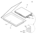
- FIG. 1 is a perspective view illustrating a concept of a secondary battery and a secondary battery dimension measurement apparatus according to a first embodiment of the present invention.
- FIG. 2 is an exploded perspective view of a secondary battery according to a first embodiment of the present invention.
- FIG 3 is a cross-sectional view showing a pouch of a secondary battery according to a first embodiment of the present invention.
- FIG. 4 is a perspective view illustrating a concept of applying a secondary battery according to a second embodiment of the present invention.
- FIG. 5 is a perspective view illustrating a concept of applying a secondary battery according to a third embodiment of the present invention.
- FIG. 6 is a perspective view illustrating a concept of applying a secondary battery according to a fourth embodiment of the present invention.
- FIG. 7 is a perspective view illustrating a concept of applying a secondary battery according to a fifth embodiment of the present invention.
- FIG. 8 is a perspective view illustrating a concept of applying a secondary battery according to a sixth embodiment of the present invention.
- FIG. 9 is a perspective view illustrating a first measurement step in a dimension measurement method of a secondary battery according to a fifth embodiment of the present invention.
- FIG. 10 is a perspective view exemplarily showing a second measurement step in the dimension measurement method of a secondary battery according to the fifth embodiment of the present invention.
- FIG. 11 is a perspective view illustrating a third measurement step in the dimension measurement method of a secondary battery according to the fifth embodiment of the present invention.
- FIG. 12 is a perspective view illustrating a first measurement step in a dimension measurement method of a secondary battery according to a sixth embodiment of the present invention.
- FIG. 13 is a perspective view illustrating a second measurement step in a dimension measurement method of a secondary battery according to a fifth embodiment of the present invention.
- FIG. 14 is a perspective view illustrating a third measurement step in the dimension measurement method of a secondary battery according to the sixth embodiment of the present invention.
- FIG. It should be noted that, in the present specification, the reference numerals are added to the constituent elements of the drawings, and the same constituent elements are assigned the same number as much as possible even if they are displayed on different drawings. Furthermore, the present invention can be embodied in various different forms and is not limited to the embodiments described herein. In the following description of the present invention, a detailed description of related arts which may unnecessarily obscure the gist of the present invention will be omitted.
- FIG. 1 is a perspective view illustrating a concept of a secondary battery and a secondary battery dimension measurement apparatus according to a first embodiment of the present invention
- FIG. 2 is an exploded perspective view illustrating a secondary battery according to a first embodiment of the present invention.
- a secondary battery 10 according to a first embodiment of the present invention includes a pouch 11 and a pouch 11 that accommodate the electrode assembly 12 and the electrode assembly 12 therein And a fluorescent reference marking portion 14 which is applied to a part of the outer surface and is made of a fluorescent substance.
- the electrode assembly 12 is a chargeable and dischargeable power generation element, and the electrode 12c and the separation membrane 12d are assembled and alternately stacked to form a structure.
- the electrode 12c may be composed of the anode 12a and the cathode 12b.
- the electrode assembly 12 may have a structure in which the anode 12a / the separation membrane 12d / the cathode 12b are alternately stacked.
- the separation membrane 12d may be located between the anode 12a and the cathode 12b, the outside of the anode 12a, and the outside of the cathode 12b.
- the separator 12d is made of an insulating material and electrically insulates between the anode 12a and the cathode 12b.
- the separation membrane 12d may be formed of, for example, a polyolefin-based resin film such as polyethylene or polypropylene having micropores.
- the electrode tab 13 is connected to the electrode 12c at one side thereof and is electrically connected to the electrode 12c.
- FIG 3 is a cross-sectional view showing a pouch of a secondary battery according to a first embodiment of the present invention.
- the pouch 11 accommodates the electrode assembly 12 and the electrode tab 13 therein.
- the pouch 11 may be formed with a body 11a that accommodates the electrode assembly 12 and the electrode tabs 13.
- the receiving portion T which is a space for receiving the electrode assembly 12, may be formed inside the body 11a.
- the pouch 11 is formed of a plurality of layers and may be laminated from the outside to the inside with a nylon 11b layer, an aluminum (Al) layer 11c, and a resin layer 11d. That is, the pouch 11 has the resin layer 11d made of synthetic resin, the middle layer made of the aluminum layer 11c, the outermost layer made of the nylon layer 11b, ≪ / RTI > At this time, the resin layer 11d may be made of, for example, polypropylene (PP).
- PP polypropylene
- the fluorescent reference marking unit 14 is applied to a part of the outer surface of the pouch 11, and may include a fluorescent material.
- the fluorescent material may be formed of a transparent fluorescent material which is visible upon ultraviolet irradiation. Accordingly, the fluorescence reference marking unit 14 can emit fluorescence (light) upon irradiation with electromagnetic waves so as to become a reference point for measurement of the dimension of the secondary battery 10.
- the fluorescent material may be a transparent fluorescent material which is invisible to visible light and absorbs ultraviolet light (330 to 380 nm) and exhibits a fluorescence peak in the range of 400 nm to 650 nm.
- the transparent fluorescent material may be composed of any one of inorganic fluorescent pigment, organic fluorescent pigment and organic fluorescent dye.
- the inorganic fluorescent pigment may be composed of any one of tungstate, hetrate, silicate, and phosphate of an alkaline earth metal such as calcium tungstate, calcium magnesium hydrate, barium silicate, calcium phosphate and calcium phosphate.
- the organic fluorescent pigment may be, for example, 2,5, thiophendi (5-tert-butyl-1,3 benzooxazole), 4,4'-bis (benzoxazole- Fluorescent dyes such as 4,4'-bis (4-phenyl-1,2,3-triazol-2-yl) stilbene-2 ', sodium 2'- (2 H-naphtho [l, 2-d] -triazol-2-yl) Coumarin derivatives such as coumarin, coumarin derivatives such as 1- (4-azidosulfonylphenyl) -3- (4-chlorophenyl) -2-pyrazoline, naphtharide derivatives, stilbene derivatives, benzothiazole derivatives, , Benzoxazole derivatives, benzidine derivatives, and oxigenone derivatives.
- 2,5, thiophendi 5-tert-butyl-1,3 benzooxazole
- 4,4'-bis (benzoxazole- Fluorescent dyes
- the organic fluorescent dyes include, for example, 4,4'-bis (4-phenyl-1,2,3-triazol-2-yl) stilbene- 2-yl) coumarin, 3-phenyl-7- (2 H-naphtho [1,2-d] -triazole- Coumarin derivatives such as coumarin and 1- (4-azidosulfonylphenyl) -3- (4-chlorophenyl) -2-pyrazoline, naphtharide derivatives, stilbene derivatives, benzothiazole derivatives, An imidazole derivative, a benzoxazole derivative, a benzidine derivative, or an oxigenone derivative.
- the fluorescent material may be a transparent or colorless fluorescent dye that absorbs ultraviolet light (330 to 380 nm) and emits blue-violet light (400 to 450 nm) of visible light as fluorescence.
- the fluorescent material may be composed of a coumarin-based or diazoyl-based fluorescent brightening agent for polyamide-based fibers such as nylon, which is dyed with an acid dye-based dyeing principle. Accordingly, the fluorescent material can be easily adhered when the nylon layer 11b is formed at the outermost periphery of the pouch 11 (see FIG. 3)
- the fluorescence reference marking unit 14 may further include an ultraviolet absorbing material. Accordingly, the ultraviolet absorber can induce the fluorescent substance to emit more fluorescence. Therefore, the recognition of the fluorescent reference marking section 14 can be made easier.
- the ultraviolet absorbing material is, for example, 2-hydroxybenzophenone, 5-chloro-2-hydroxybenzophenone, 2,4-dihydroxybenzophenone, 2-hydroxy- Benzophenone-based ultraviolet absorbing substances such as hydroxy-4-octyloxybenzophenone, 4-decyloxy 2-hydroxybenzophenone and 2,2 ', 4,4'-tetrahydroxybenzophenone, 2- (2-hydroxy-3-t-butylphenyl) benzotriazole, 2- (2-hydroxy- Butyl-5-methylphenyl) -5-chlorobenzotriazole, 2- (2-hydroxy-3,5-di- Butyl-5-methylphenyl) benzotriazole, 2- (2-hydroxy-5-t-octylphenyl) benzotriazole, 2- Benzotriazole-based ultraviolet absorbing materials such as triazole and the like, benzoates such as 2,4-di-t-butylphenyl-3,5-di-t-butyl-
- the fluorescent reference marking unit 14 in the secondary battery 10 according to the first embodiment of the present invention may be located at the center of the outer surface of the secondary battery 10, for example. At this time, the fluorescent reference marking unit 14 may be located at the center of the upper surface or the lower surface of the pouch 11 of the secondary battery 10.
- FIG. 4 is a perspective view illustrating a concept of applying a secondary battery according to a second embodiment of the present invention.
- the fluorescent reference marking unit 24 may be located on both sides of the outer surface of the secondary battery 20, for example.
- the fluorescent reference marking unit 24 may include a fluorescent reference marking unit 24a disposed on one side of the upper surface or the lower surface of the pouch 11, and a fluorescent reference marking unit 24b positioned on the other side.
- the dimensions of the secondary battery 20 can be measured based on the fluorescent reference marking unit 24 positioned on both sides of the pouch 11 when the fluorescent light is emitted through ultraviolet rays.
- the width of the secondary battery 20 can be detected by detecting the distance of the fluorescent reference marking unit 24 located on both sides of the pouch 11.
- FIG. 5 is a perspective view illustrating a concept of applying a secondary battery according to a third embodiment of the present invention.
- the fluorescent reference marking unit 34 in the secondary battery 30 may be located at the edge of the secondary battery 30, for example.
- the fluorescent reference marking portion 34 may be located at an edge portion on the upper surface or the lower surface of the pouch 11.
- the fluorescent reference marking portion 34 is formed of a first fluorescent reference marking portion 34a positioned at a first side edge of four corners of the pouch 11 and a second fluorescent reference marking portion 34b positioned at a second side edge of four corners of the pouch 11 And a second fluorescent reference marking unit 34b.
- the dimension of the secondary battery 30 can be measured based on the fluorescence reference marking unit 34 located at the corner of the pouch 11 when the fluorescence is generated through ultraviolet rays.
- the fluorescence reference marking unit 34 positioned at any one of the four corners of the pouch 11 can be used as the reference start point (0, 0) of the X, Y coordinates when measuring the dimension of the pouch 11 have.
- FIG. 6 is a perspective view illustrating a concept of applying a secondary battery according to a fourth embodiment of the present invention.
- the fluorescent reference marking portion 44 is formed of a line formed along the longitudinal direction, the width direction, or the thickness direction of the secondary battery 40 .
- the dimension of the secondary battery 40 can be measured based on the fluorescence reference marking portion 44 formed in a line shape along the longitudinal direction, the width direction, and the thickness direction of the pouch 11 when the fluorescent light is emitted through ultraviolet rays .
- the length of the length of the fluorescent reference marking portion 44a formed in the longitudinal direction of the pouch 11 in the fluorescent reference marking portion 44 can be measured to detect the length of the pouch 11,
- the width of the pouch 11 can be detected by measuring the length of the line of the width fluorescent reference marking portion 44b formed in the width direction of the pouch 11 so that the thickness of the pouch 11 can be detected and the thick fluorescent reference marking portion 44c formed in the thickness direction of the pouch 11,
- the thickness of the pouch 11 can be detected by measuring the length of the line.
- FIG. 7 is a perspective view illustrating a concept of applying a secondary battery according to a fifth embodiment of the present invention.
- the fluorescent reference marking unit 54 includes a line (line) connecting the centers of the secondary batteries 50 in the full- ) Of the pouch body 51, as shown in Fig.
- the secondary battery 50 may be configured such that the wing portions 51d and 51e located on both sides of the body 51a of the pouch 51 are folded.
- both side distances W3 and W4 can be measured in the full width direction W from the body 51a of the pouch 51 around the fluorescence reference notation 54 of the pouch 51 have. That is, the dimensions of both sides of the body 51a of the pouch 51 can be measured based on the fluorescent reference marking unit 54 to extract the full width. Accordingly, it is possible to measure the full width and the entire width variation of the secondary battery 50 according to the manufacturing process of the secondary battery 50 based on the fluorescent reference marking portion 54 of the pouch 51, and the tolerance analysis can be easily performed.
- FIG. 8 is a perspective view illustrating a concept of applying a secondary battery according to a sixth embodiment of the present invention.
- the fluorescent reference marking unit 64 includes a line (line) connecting the centers of the secondary batteries 60 in the longitudinal direction L of the secondary battery 60
- the body 61a of the pouch 61 can be formed.
- the secondary battery 60 may be configured such that the wing portions 61d and 61e located on both sides of the body 61a of the pouch 61 are folded.
- both side distances L1 and L2 are measured from the body 61a of the pouch 61 in the longitudinal direction L about the fluorescent reference marking portion 64 of the pouch 61 . Accordingly, it is possible to measure the total length and the total length variation of the secondary battery 60 according to the manufacturing process of the secondary battery 60 based on the fluorescence reference marking portion 64 of the pouch 61, thereby facilitating tolerance analysis.
- a secondary cell dimension measurement apparatus 100 is an apparatus for measuring a dimension of a secondary battery, 14 for emitting ultraviolet rays and a laser measuring unit 120 for irradiating and receiving laser beams to the secondary battery 10.
- the apparatus for measuring secondary battery dimension 100 can measure the dimensions of the secondary batteries 10, 20, 30, 40, 50, and 60 according to the first to sixth embodiments It is a measuring device. Therefore, the present embodiment will briefly describe the contents overlapping with the above-described embodiment, and focus on the differences. (Refer to Fig. 1, Fig. 4 to Fig. 8)
- the ultraviolet ray irradiating unit 110 irradiates the secondary battery 10 with ultraviolet rays, and is applied to a part of the outer surface of the pouch 11 and has a fluorescent reference marking unit 14 including a fluorescent material, Lt; / RTI >
- the ultraviolet ray irradiating unit 110 irradiates ultraviolet rays toward the fluorescent reference marking unit 14 located at least one of the outer edge, the side, or the center of the secondary battery 10, . ≪ / RTI > 6, the ultraviolet ray irradiating unit 110 irradiates ultraviolet rays toward the fluorescent reference marking unit 14, which is a line formed along the longitudinal direction, the widthwise direction, or the thickness direction of the secondary battery 10 . 7 and 8, the ultraviolet ray irradiating unit 110 includes a fluorescent reference marking unit 54, 64 formed on the pouch in the form of a line connecting the centers of the secondary batteries 50, ) To ultraviolet rays. Referring to FIG. 1, the ultraviolet ray irradiating unit 110 can irradiate ultraviolet rays toward the fluorescent reference marking unit 14 made of a transparent fluorescent material visible during ultraviolet ray irradiation.
- the laser measuring unit 120 irradiates and receives the laser beam to the secondary battery 10 and measures the dimension of the secondary battery 10 based on the fluorescence reference notation 14 detected by the fluorescence.
- the laser measuring unit 120 may include a laser irradiating unit 121, a light receiving unit 122, and a calculating unit 123.
- the laser irradiation unit 121 can irradiate the secondary battery 10 with laser light.
- the light receiving unit 122 receives the reflected light of the laser beam irradiated on the secondary battery 10 and can receive the fluorescence of the fluorescent reference marking unit 14 that is fluoresced by the ultraviolet light irradiated by the ultraviolet irradiating unit 110.
- the operation unit 123 analyzes the reflected light of the laser beam received through the light receiving unit 122 and the fluorescence detection value of the fluorescent reference marking unit 14 and determines the dimension of the secondary battery 10 based on the fluorescent reference marking unit 14 Dimension) can be calculated.
- the calculating unit 123 can calculate the total length or the entire width of the body 11a of the pouch 11 or the whole of the pouch 11 for each manufacturing process of the secondary battery 10 based on the fluorescent reference marking unit 14. [
- the secondary cell dimension measurement apparatus 100 can measure the dimension of the secondary cell 10 based on the fluorescence reference marking unit 14, thereby preventing the measurement error from occurring Can be minimized.
- the fluorescent reference marking unit 14 may be located at the center of the outer surface of the secondary battery 10.
- the fluorescent reference marking unit 24 may be located on both sides of the outer surface of the secondary battery 20.
- the fluorescent reference marking unit 34 may be positioned at an edge of the outer surface of the secondary battery 30.
- the fluorescent reference marking unit 44 is formed on a line formed along the longitudinal direction, the width direction, or the thickness direction of the secondary battery 40 Or at least one of them.
- the fluorescent reference marking unit 54 is formed in a line shape in which centers are connected in the full width direction W of the secondary battery 50 And can be formed in the pouch 51.
- the fluorescent reference marking unit 64 is formed in a line shape in which centers of the secondary batteries 60 are aligned in the longitudinal direction L And can be formed in the pouch 61.
- a method of measuring a secondary battery dimension includes a pouch 11 having a body 11a for receiving an electrode assembly 12 and an electrode assembly 12,
- a method of measuring the dimension of the battery 10 includes a fluorescent marking step of applying a fluorescent reference marking portion 14 to the outer surface of the pouch 11 and labeling the fluorescent marking portion with fluorescent light, An ultraviolet light irradiation step for fluorescently illuminating the fluorescent reference marking section 14 and a dimension measurement step for measuring a dimension of the secondary battery 10 based on the fluorescent reference marking section 14.
- the method of measuring the secondary battery dimension according to the embodiment of the present invention is the same as the method of measuring the secondary battery dimension according to the first to sixth embodiments described above, , 20, 30, 40, 50, 60). Therefore, the present embodiment will briefly describe the contents overlapping with the above-described embodiment, and focus on the differences. (Refer to Figs. 1 and 4 to 8)
- the fluorescence notation step may be performed by applying a fluorescent reference marking unit 14 including a fluorescent material on a part of the outer surface of the pouch 11.
- the ultraviolet ray irradiation step can irradiate the pouch 11 with ultraviolet rays to fluoresce the fluorescent reference marking portion 14 applied to a part of the outer surface of the pouch 11.
- the pouch 11 is irradiated with laser light and received, and the dimension of the secondary battery 10 can be measured based on the fluorescence reference notation 14 detected by fluorescence.
- the dimension measuring step includes a laser irradiating step of irradiating laser light, a light receiving step of receiving the reflected light of the irradiated laser light and receiving the fluorescence of the fluorescent reference marking part 14 which is irradiated with ultraviolet light, And an operation step of analyzing the reflected light of the laser light and the fluorescence detection value of the fluorescence reference marking unit 14 and calculating the dimension based on the fluorescence reference marking unit 14.
- FIG. 9 is a perspective view illustrating a first measurement step in a dimension measurement method of a secondary battery according to a fifth embodiment of the present invention
- FIG. 10 is a diagram illustrating a dimension measurement method of a secondary battery according to a fifth embodiment of the present invention
- FIG. 11 is a perspective view illustrating a third measurement step in a dimension measurement method of a secondary battery according to a fifth embodiment of the present invention.
- FIG. 12 is a perspective view illustrating a first measurement step in a dimension measurement method of a secondary battery according to a sixth embodiment of the present invention
- FIG. 13 is a diagram illustrating a dimension measurement of the secondary battery according to the fifth embodiment of the present invention
- FIG. 14 is a perspective view exemplarily showing a third measurement step in the dimension measurement method of a secondary battery according to the sixth embodiment of the present invention.
- the fluorescent labeling step can perform fluorescent labeling of the fluorescent reference marking unit 14 on at least one of the corner, the side, or the center of the secondary battery 10.
- the fluorescent labeling step can perform fluorescent labeling of the fluorescent reference marking unit 14 on at least one of the lines formed along the longitudinal direction, the width direction, or the thickness direction of the secondary battery 10 .
- the fluorescent marking step is performed in the body 51a, 61a of the pouch 51, 61 in the longitudinal direction L or the full width direction W of the secondary batteries 50,
- the fluorescent reference marking unit 14 can be fluorescently displayed in the form of a line connecting the fluorescent reference marking unit 14 and the fluorescent reference marking unit 14.
- the fluorescent reference marking unit 14 can be fluorescently displayed at the center of the outer surface of the secondary battery 10 have. Therefore, the size of the secondary battery 10 can be precisely measured by calculating the dimension based on the fluorescence reference marking unit 14 in the dimension measurement step.
- the fluorescent reference marking unit 24 is fluorescently marked on both sides of the outer surface of the secondary battery 20 . Accordingly, the dimension of the secondary battery 20 can be precisely measured by calculating the dimension based on the fluorescent reference marking unit 24 in the dimension measurement step.
- the fluorescent reference marking unit 34 can be fluorescently marked at the corner of the outer surface of the secondary battery 30 have. Therefore, in the dimension measurement step, the size of the secondary battery 30 can be precisely measured by calculating the dimension based on the fluorescent reference marking unit 34.
- the fluorescent marking step may include at least one of the lines formed along the length direction, the width direction, or the thickness direction of the secondary battery 40.
- the fluorescent reference marking unit 44 can be labeled with fluorescent light. Therefore, in the dimension measurement step, the size of the secondary battery 40 can be precisely measured by calculating the dimension based on the fluorescent reference marking unit 44.
- the fluorescent marking step may be performed in the form of a line connecting centers of the secondary batteries 50 in the full width direction of the pouch 51
- the fluorescence reference marking unit 54 can be indicated by fluorescence.
- the dimension measurement step may include a first measurement for measuring the two side distances W1 and W2 of the body 51a from the pouch 51 around the fluorescent reference marking unit 54 before the electrode assembly is received in the pouch 51 A second measuring step of measuring the distance between the side of the body 51a and the side of the body 51a from the pouch 51 around the fluorescent reference marking unit after the electrode assembly is received in the body 51a of the pouch 51, And a third measurement step of measuring the both side distances W3 and W4 of the pouch 51 around the fluorescent reference marking portion 54 after the wing portion is folded in the pouch 51 containing the electrode assembly can do.
- the entire width of the body 51a of the pouch 51 can be measured. That is, the dimensions of both sides of the body 51a of the pouch 51 can be measured based on the fluorescent reference marking unit 54 to extract the full width.
- the pouch 51 is folded around a hypothetical line, and a portion of the pouch 51 is degassed and then degassed to seal the body 51a of the pouch 51 Full width can be measured.
- the total width of the pouches 51 including the wing portions 51d and 51e after folding the wing portions 51d and 51e located on both sides of the body 51a in the pouch 51 containing the electrode assembly in the third measurement step Can be measured.
- the calculation step compares the measured full width value with the full width standard value of each process stored in the memory (not shown), and the tolerance can be extracted for each process.
- the full width of the pouch 51 can be measured by the manufacturing process of the secondary battery 50 around the fluorescence reference marking portion, so that it is easy to measure the full width and overall width variation by each process, .
- the fluorescent marking step may be performed in the form of a line connecting centers of the secondary batteries 60 in the longitudinal direction of the pouch 61
- the fluorescence reference marking portion 64 can be indicated by fluorescence.
- the dimension measurement step may include a first measurement for measuring the two side distances L1 and L2 of the body 61a from the pouch 61 around the fluorescent reference marking unit 64 before the electrode assembly is received in the pouch 61, The electrode assembly is housed in the body 61a of the pouch 61 and the distance L1 and L2 of the body 61a are measured from the pouch 61 around the fluorescent reference marking unit 64 And a second measuring step.
- the dimension measurement step may include measuring the dimensions of the pouch 61 on both sides of the pouch 61 around the fluorescent reference marking unit 64 after the wing parts 61d and 61e are folded in the pouch 61 containing the electrode assembly, And a third measuring step of measuring distances L1 and L2.
- the electric field for the body 61a of the pouch 61 can be measured have.
- the total length of the body 61a of the pouch 61 when the accommodating space is sealed after being folded around a hypothetical line as a sheet-like pouch 61 is measured .
- the electric field of the pouch 61 can be measured after folding the wing portions 61d and 61e located on both sides of the body 61a in the pouch 61 accommodating the electrode assembly .
- the calculation step compares the measured electric field value with the electric field standard value of each process stored in the memory, and the tolerance can be extracted for each process.
- the electric field of the pouch 61 can be measured by the manufacturing process of the secondary battery 60 around the fluorescent reference marking unit 64, so that it is easy to measure the electric field and the electric field change amount per process, Analysis can be easy.
Landscapes
- Physics & Mathematics (AREA)
- Chemical & Material Sciences (AREA)
- Chemical Kinetics & Catalysis (AREA)
- Electrochemistry (AREA)
- General Chemical & Material Sciences (AREA)
- Spectroscopy & Molecular Physics (AREA)
- General Physics & Mathematics (AREA)
- Engineering & Computer Science (AREA)
- Manufacturing & Machinery (AREA)
- Sealing Battery Cases Or Jackets (AREA)
- Battery Mounting, Suspending (AREA)
- Secondary Cells (AREA)
Abstract
본 발명은 이차전지, 이차전지 디멘션 측정장치, 및 이차전지 디멘션 측정방법에 관한 것으로, 본 발명에 이차전지는 이차전지로서, 전극 및 분리막이 교대로 적층되어 결집된 전극 조립체와, 상기 전극 조립체를 내측에 수용하는 파우치 및 상기 파우치의 외면 일부에 도포되고, 형광물질을 포함하여 이루어진 형광 기준 표기부를 포함하고, 상기 이차전지의 디멘션(Dimension) 측정을 위한 기준점이 되도록 상기 형광 기준 표기부는 전자기파 조사 시 형광(光)을 발한다.
Description
관련출원과의 상호인용
본 출원은 2017년 11월 06일자 한국특허출원 제10-2017-0146571호 및 2018년 11월 02일자 한국특허출원 제10-2018-0133294호에 기초한 우선권의 이익을 주장하며, 해당 한국특허출원의 문헌에 개시된 모든 내용은 본 명세서의 일부로서 포함된다.
기술분야
본 발명은 이차전지 및 이차전지 디멘션 측정장치에 관한 것이다.
이차 전지는 일차 전지와는 달리 재충전이 가능하고, 또 소형 및 대용량화 가능성으로 인해 근래에 많이 연구 개발되고 있다. 모바일 기기에 대한 기술 개발과 수요가 증가함에 따라 에너지원으로서의 이차 전지의 수요가 급격하게 증가하고 있다.
이차 전지는 전지 케이스의 형상에 따라, 코인형 전지, 원통형 전지, 각형 전지, 및 파우치형 전지로 분류된다. 이차 전지에서 전지 케이스 내부에 장착되는 전극 조립체는 전극 및 분리막의 적층 구조로 이루어진 충방전이 가능한 발전소자이다.
또한, 전극 조립체는 활물질이 도포된 시트형의 양극과 음극 사이에 분리막을 개재(介在)하여 권취한 젤리 롤(Jelly-roll)형, 다수의 양극과 음극을 분리막이 개재된 상태에서 순차적으로 적층한 스택형, 및 스택형의 단위 셀들을 긴 길이의 분리 필름으로 권취한 스택/폴딩형으로 대략 분류할 수 있다.
최근에는, 스택형 또는 스택/폴딩형 전극조립체를 알루미늄 라미네이트 시트의 파우치(Pouch)형 전지 케이스(Case)에 내장한 구조의 파우치형 전지가, 낮은 제조비, 작은 중량, 용이한 형태 변형 등을 이유로, 많은 관심을 모으고 있고 또한 그것의 사용량이 점차적으로 증가하고 있다.
이러한, 파우치형 전지의 경우 디멘션(Dimension) 측정을 위한 기준점이 존재하지 않으며, 이에 따라 측정 시 마다 측정 오차가 발생되는 문제가 있다.
본 발명의 하나의 관점은 이차전지의 디멘션(Dimension)을 측정이 용이하고, 측정오차 발생을 방지하거나 현저히 감소시킬 수 있는 이차전지, 이차전지 디멘션 측정장치 및 이차전지 디멘션 측정방법을 제공하기 위한 것이다.
본 발명의 다른 관점은 이차전지의 공차 분석이 용이한 이차전지 및 이차전지 디멘션 측정장치 및 이차전지 디멘션 측정방법을 제공하기 위한 것이다.
본 발명의 실시예에 따른 이차전지는, 이차전지로서, 전극 및 분리막이 교대로 적층되어 결집된 전극 조립체와, 상기 전극 조립체를 내측에 수용하는 파우치 및 상기 파우치의 외면 일부에 도포되고, 형광물질을 포함하여 이루어진 형광 기준 표기부를 포함하고, 상기 이차전지의 디멘션(Dimension) 측정을 위한 기준점이 되도록 상기 형광 기준 표기부는 전자기파 조사 시 형광(光)을 발할 수 있다.
또한, 본 발명의 실시예에 따른 이차전지 디멘션 측정장치는, 전극 조립체 및 상기 전극 조립체를 수용하는 파우치를 포함하는 이차전지의 디멘션(Dimension)을 측정하는 장치로서, 상기 파우치에 자외선을 조사하여, 상기 파우치의 외면 일부에 도포되고 형광물질을 포함하여 이루어진 형광 기준 표기부를 형광시키는 자외선 조사부 및 상기 파우치에 레이저광을 조사 및 수광하고, 형광되어 검출된 상기 형광 기준 표기부를 기준으로 상기 이차전지의 디멘션을 측정하는 레이저 측정부를 포함할 수 있다.
아울러, 본 발명의 실시예에 따른 이차전지 디멘션 측정방법은, 전극 조립체 및 상기 전극 조립체를 수용하는 몸체가 형성된 파우치를 포함하는 이차전지의 디멘션(Dimension)을 측정하는 방법으로서, 상기 파우치의 외면 일부에 형광물질을 포함하여 이루어진 형광 기준 표기부를 도포하여 형광 표기하는 형광 표기 단계; 상기 파우치에 자외선을 조사하여, 상기 파우치의 외면 일부에 도포된 상기 형광 기준 표기부를 형광시키는 자외선 조사 단계, 및 상기 파우치에 레이저광을 조사 및 수광하고, 형광되어 검출된 상기 형광 기준 표기부를 기준으로 상기 이차전지의 디멘션을 측정하는 디멘션 측정단계를 포함할 수 있다.
본 발명에 따르면, 이차전지의 파우치 외면에 형광 기준 표기부가 도포되어 이차전지의 디멘션(Dimension) 측정시 기준점으로 이용할 수 있어 측정이 용이하고, 측정오차 발생을 방지하거나 현저히 감소시킬 수 있다.
또한, 파우치 외면에 위치된 형광 기준 표기부를 기준으로 이차전지의 공정별 전폭 및 전장 변화량 측정이 용이하고, 이로 인해 공차 분석이 용이할 수 있다.
도 1은 본 발명의 제1 실시예에 따른 이차전지 및 이차전지 디멘션 측정장치의 개념을 나타낸 사시도이다.
도 2는 본 발명의 제1 실시예에 따른 이차전지를 나타낸 분리 사시도이다.
도 3은 본 발명의 제1 실시예에 따른 이차전지에서 파우치를 나타낸 요부 단면도이다.
도 4는 본 발명의 제2 실시예에 따른 이차전지가 적용된 개념을 나타낸 사시도이다.
도 5는 본 발명의 제3 실시예에 따른 이차전지가 적용된 개념을 나타낸 사시도이다.
도 6은 본 발명의 제4 실시예에 따른 이차전지가 적용된 개념을 나타낸 사시도이다.
도 7은 본 발명의 제5 실시예에 따른 이차전지가 적용된 개념을 나타낸 사시도이다.
도 8은 본 발명의 제6 실시예에 따른 이차전지가 적용된 개념을 나타낸 사시도이다.
도 9는 본 발명의 제5 실시예에 따른 이차전지의 디멘션 측정방법에서 제1 측정단계를 예시적으로 나타낸 사시도이다.
도 10은 본 발명의 제5 실시예에 따른 이차전지의 디멘션 측정방법에서 제2 측정단계를 예시적으로 나타낸 사시도이다.
도 11은 본 발명의 제5 실시예에 따른 이차전지의 디멘션 측정방법에서 제3 측정단계를 예시적으로 나타낸 사시도이다.
도 12는 본 발명의 제6 실시예에 따른 이차전지의 디멘션 측정방법에서 제1 측정단계를 예시적으로 나타낸 사시도이다.
도 13은 본 발명의 제5 실시예에 따른 이차전지의 디멘션 측정방법에서 제2 측정단계를 예시적으로 나타낸 사시도이다.
도 14는 본 발명의 제6 실시예에 따른 이차전지의 디멘션 측정방법에서 제3 측정단계를 예시적으로 나타낸 사시도이다.
본 발명의 목적, 특정한 장점들 및 신규한 특징들은 첨부된 도면들과 연관되어지는 이하의 상세한 설명과 바람직한 실시예들로부터 더욱 명백해질 것이다. 본 명세서에서 각 도면의 구성요소들에 참조번호를 부가함에 있어서, 동일한 구성 요소들에 한해서는 비록 다른 도면상에 표시되더라도 가능한 한 동일한 번호를 가지도록 하고 있음에 유의하여야 한다. 또한, 본 발명은 여러 가지 상이한 형태로 구현될 수 있으며 여기에서 설명하는 실시예에 한정되지 않는다. 그리고, 본 발명을 설명함에 있어서, 본 발명의 요지를 불필요하게 흐릴 수 있는 관련된 공지 기술에 대한 상세한 설명은 생략하도록 한다.
도 1은 본 발명의 제1 실시예에 따른 이차전지 및 이차전지 디멘션 측정장치의 개념을 나타낸 사시도이고, 도 2는 본 발명의 제1 실시예에 따른 이차전지를 나타낸 분리 사시도이다.
도 1 및 도 2를 참고하면, 본 발명의 제1 실시예에 따른 이차전지(10)는 전극 조립체(12) 및 전극 조립체(12)를 내측에 수용하는 파우치(11) 및 파우치(11)의 외면 일부에 도포되고, 형광물질을 포함하여 이루어진 형광 기준 표기부(14)를 포함한다.
전극 조립체(12)는 충방전이 가능한 발전소자로서, 전극(12c)과 분리막(12d)이 결집되어 교대로 적층된 구조를 형성한다.
전극(12c)은 양극(12a) 및 음극(12b)으로 구성될 수 있다. 이때, 전극 조립체(12)는 양극(12a)/분리막(12d)/음극(12b)이 교대로 적층된 구조로 이루어질 수 있다. 여기서, 분리막(12d)은 양극(12a)과 음극(12b) 사이와, 양극(12a)의 외측 및 음극(12b)의 외측에 위치될 수 있다.
분리막(12d)은 절연 재질로 이루어져 양극(12a)과 음극(12b) 사이를 전기적으로 절연한다. 여기서, 분리막(12d)은 예를 들어 미다공성을 가지는 폴리에칠렌, 폴리프로필렌 등 폴리올레핀계 수지막으로 형성될 수 있다.
전극 탭(13)은 전극(12c)에 일측부가 연결되어 전극(12c)과 전기적으로 연결된다.
도 3은 본 발명의 제1 실시예에 따른 이차전지에서 파우치를 나타낸 요부 단면도이다.
도 2 및 도 3을 참고하면, 파우치(11)는 전극 조립체(12) 및 전극 탭(13)을 내부에 수용한다.
또한, 파우치(11)는 전극 조립체(12) 및 전극 탭(13)을 수용하는 몸체(11a)가 형성될 수 있다. 이때 몸체(11a)의 내측으로 전극 조립체(12)를 수용하는 공간인 수용부(T)가 형성될 수 있다.
한편, 파우치(11)는 다수의 층으로 이루어져, 외측에서 내측으로 나일론(Nylon)(11b)층, 알루미늄(Al)층(11c) 및 수지층(11d)으로 적층될 수 있다. 즉, 파우치(11)는 중앙층이 알루미늄층(11c)으로 이루어지고, 최외각층이 나일론층(11b)으로 이루어지고, 수용부(T)와 인접된 내부층이 합성수지로 이루어진 수지층(11d)으로 이루어질 수 있다. 이때, 수지층(11d)은 예를 들어 폴리프로필렌(PP; polypropylene)으로 이루어질 수 있다.
도 1을 참고하면, 형광 기준 표기부(14)는 파우치(11)의 외면 일부에 도포되고, 형광물질을 포함하여 이루어질 수 있다. 이때, 형광물질은 자외선 조사 시에 시인되는 투명 형광물질로 이루어질 수 있다. 이에 따라, 형광 기준 표기부(14)는 이차전지(10)의 디멘션(Dimension) 측정을 위한 기준점이 되도록 전자기파 조사 시 형광(光)을 발할 수 있다.
보다 구체적으로, 형광물질은 일례로 가시광역으로 불가시이며 자외선광(330~380nm)을 흡수해 400nm~650 nm의 범위에 형광 피크를 나타내는 투명 형광물질로 이루어질 수 있다. 여기서, 투명 형광물질은 무기 형광 안료, 유기 형광 안료 또는 유기 형광 염료 중에서 어느 하나로 이루어질 수 있다. 이때, 무기 형광 안료는 예를 들어 텅스텐산 칼슘, 히산 마그네슘 칼슘, 규산 바륨, 인산 칼슘 및 인산 칼슘 아연 등의 알칼리토류 금속의 텅스텐산염, 히산염, 규산염, 인산염 중에서 어느 하나로 이루어질 수 있다. 또한, 유기 형광 안료는 예를들어 2,5,티오펜디일(5-tert-부틸-1,3 벤조옥사졸), 4,4'-비스(벤조옥사졸-2-루이스) 스틸벤;유기 형광 염료, 예를 들면 4,4'-비스(4-페닐-1,2,3-트리아졸-2-일) 스틸벤-2',2'-디설폰산 나트륨,3-페닐-7-(4-메틸-5-페닐-1,2,3-트리아졸-2-일) 쿠마린,3-페닐-7-(2 H-나프토[1,2-d]-트리아졸-2-일) 쿠마린,1-(4-아시드스르호니르페닐)-3-(4-클로로페닐)-2-피라졸린 등의 쿠마린 유도체, 나후타르이미드 유도체, 스틸벤 유도체, 벤조티아졸 유도체, 벤조이미다졸 유도체, 벤조옥사졸 유도체, 벤지딘 유도체, 옥시지논 유도체 중에서 어느 하나로 이루어질 수 있다. 그리고, 유기 형광 염료는 예를들어 4,4'-비스(4-페닐-1,2,3-트리아졸-2-일) 스틸벤-2',2'-디설폰산 나트륨,3-페닐-7-(4-메틸-5-페닐-1,2,3-트리아졸-2-일) 쿠마린,3-페닐-7-(2 H-나프토[1,2-d]-트리아졸-2-일) 쿠마린,1-(4-아시드스르호니르페닐)-3-(4-클로로페닐)-2-피라졸린 등의 쿠마린 유도체, 나후타르이미드 유도체, 스틸벤 유도체, 벤조티아졸 유도체, 벤조이미다졸 유도체, 벤조옥사졸 유도체, 벤지딘 유도체, 옥시지논 유도체 중에서 어느 하나로 이루어질 수 있다.
한편, 형광물질은 다른 예로 자외선광(330~380nm)을 흡수하여 가시부의 청자색의 광(400~450nm)을 형광으로 발발하는 투명 및 무색 형광 염료로 이루어질 수 있다. 이때, 형광물질은 예를들어 나일론 등의 폴리아미드계 섬유 용으로 산성염료타입의 염착 원리로 염착되는 쿠마린계 또는 디아졸린계 형광 증백제로 이루어질 수 있다. 이에 따라, 파우치(11)의 최외각에 나일론층(11b)이 형성 시 형광물질이 용이하게 염착될 수 있다.(참조 도 3)
한편, 형광 기준 표기부(14)는 자외선 흡수물질을 더 포함할 수 있다. 이에 따라, 자외선 흡수제는 형광물질이 형광을 보다 더 발광하도록 유도할 수 있다. 따라서, 형광 기준 표기부(14)의 인식을 보다 용이하게 할 수 있다.
그리고, 자외선 흡수물질은 예를 들어 2-하이드록시벤조페논, 5-클로로-2-하이드록시벤조페논, 2,4-디하이드록시벤조페논, 2-하이드록시-4-메톡시벤조페논, 2-하이드록시-4-옥틸옥시 벤조페논, 4-드데시로키시2-하이드록시벤조페논, 2,2',4,4'-테트라히드록시벤조페논 등의 벤조페논계 자외선 흡수물질, 2-(2-하이드록시-5-메틸 페닐) 벤조트리아졸,2-(2-하이드록시-3,5-디-t-부틸 페닐) 벤조트리아졸,2-(2-하이드록시-3-t-부틸-5-메틸 페닐)-5-클로로벤조트리아졸,2-(2-하이드록시-3,5-디-t-펜틸페닐) 벤조트리아졸,2-(2-하이드록시-3-t-부틸-5-메틸 페닐) 벤조트리아졸,2-(2-하이드록시-5-t-옥틸 페닐) 벤조트리아졸,2-(2-하이드록시-3,5-디-t-아밀 페닐) 벤조트리아졸 등의 벤조트리아졸계 자외선 흡수물질, 2,4-디-t-부틸 페닐-3,5-디-t-부틸-4-히드록시벤조에이트 등의 벤조에이트계 자외선 흡수물질, 살리실산계 자외선 흡수물질, 또는 시아노아크릴레이트계 자외선 흡수물질 중에서 어느 하나로 이루어질 수 있다.
한편, 도 1을 참고하면 본 발명의 제1 실시예에 따른 이차전지(10)에서 형광 기준 표기부(14)는 예를 들어 이차전지(10)의 외면에서 중앙부에 위치될 수 있다. 이때, 형광 기준 표기부(14)는 이차전지(10)의 파우치(11)에서 상면 또는 하면에 서 중앙부에 위치될 수 있다.
도 4는 본 발명의 제2 실시예에 따른 이차전지가 적용된 개념을 나타낸 사시도이다.
또한, 도 4를 참고하여 본 발명의 제2 실시예에 따른 이차전지(20)에서 형광 기준 표기부(24)는 예를 들어 이차전지(20)의 외면에서 양측부에 위치될 수 있다. 여기서, 형광 기준 표기부(24)는 파우치(11)의 상면 또는 하면에서 일측에 위치되는 일측 형광 기준 표기부(24a) 및 타측에 위치되는 형광 기준 표기부(24b)를 포함할 수 있다.
이에 따라, 자외선을 통한 형광 발현 시 파우치(11)의 양측에 위치된 형광 기준 표기부(24)를 기준으로 이차전지(20)의 디멘션을 측정할 수 있다. 이때, 예를 들어 파우치(11)의 양측에 위치된 형광 기준 표기부(24)의 거리를 검출하여 이차전지(20)의 폭 치수를 검출할 수 있다.
도 5는 본 발명의 제3 실시예에 따른 이차전지가 적용된 개념을 나타낸 사시도이다.
또한, 도 5를 참고하여 본 발명의 제3 실시예에 따른 이차전지(30)에서 형광 기준 표기부(34)는 예를 들어 이차전지(30)의 모서리에 위치될 수 있다. 여기서, 형광 기준 표기부(34)는 파우치(11)의 상면 또는 하면에서 모서리부에 위치될 수 있다. 이때, 형광 기준 표기부(34)는 파우치(11)의 4모서리에서 제1측 모서리에 위치되는 제1 형광 기준 표기부(34a) 및 파우치(11)의 4모서리에서 제2측 모서리에 위치되는 제2 형광 기준 표기부(34b)를 포함할 수 있다.
이에 따라, 자외선을 통한 형광 발현 시 파우치(11)의 모서리에 위치된 형광 기준 표기부(34)를 기준으로 이차전지(30)의 디멘션을 측정할 수 있다. 이때, 예를 들어 파우치(11)의 4모서리 중 어느 하나에 위치된 형광 기준 표기부(34)를 파우치(11)의 디멘션 측정 시 X,Y좌표의 기준 시작점(0,0)으로 이용될 수 있다.
도 6은 본 발명의 제4 실시예에 따른 이차전지가 적용된 개념을 나타낸 사시도이다.
또한, 도 6을 참고하여 본 발명의 제4 실시예에 따른 이차전지(40)에서 형광 기준 표기부(44)는 이차전지(40)의 길이 방향, 폭 방향 또는 두께 방향을 따라 형성된 라인으로 이루어질 수 있다.
이에 따라, 자외선을 통한 형광 발현 시 파우치(11)의 길이 방향, 폭 방향 및 두께 방향을 따라 라인 형태로 형성된 형광 기준 표기부(44)를 기준으로 이차전지(40)의 디멘션을 측정할 수 있다.
이때, 예를 들어 형광 기준 표기부(44)에서 파우치(11)의 길이 방향으로 형성된 길이 형광 기준 표기부(44a) 라인의 길이를 측정하면 파우치(11)의 길이를 검출할 수 있고, 파우치(11)의 폭 방향으로 형성된 폭 형광 기준 표기부(44b) 라인의 길이를 측정하면 파우치(11)의 폭을 검출할 수 있고, 파우치(11)의 두께 방향으로 형성된 두께 형광 기준 표기부(44c) 라인의 길이를 측정하면 파우치(11)의 두께를 검출할 수 있다.
도 7은 본 발명의 제5 실시예에 따른 이차전지가 적용된 개념을 나타낸 사시도이다.
또한, 도 7을 참고하면, 본 발명의 제5 실시예에 따른 이차전지(50)에서 형광 기준 표기부(54)는 이차전지(50)의 전폭 방향(W)으로 중심을 연결한 라인(Line) 형태로 파우치(51)의 몸체(51a)에 형성될 수 있다. 이때, 이차전지(50)는 예를 들어 파우치(51)에서 몸체(51a)의 양측에 위치된 윙(Wing)부(51d,51e)가 폴딩된 형태일 수 있다.
따라서, 자외선을 통한 형광 발현 시 파우치(51)의 형광 기준 표기부(54)를 중심으로 파우치(51)의 몸체(51a)에서 전폭 방향(W)으로 양측 거리(W3,W4)를 측정할 수 있다. 즉, 형광 기준 표기부(54)를 기준으로 파우치(51)의 몸체(51a) 양측의 디멘션 측정하여 전폭을 추출할 수 있다. 이에 따라, 파우치(51)의 형광 기준 표기부(54)를 기준으로 이차전지(50)의 제조공정별 전폭 및 전폭 변화량 측정이 가능하여 공차 분석이 용이할 수 있다.
도 8은 본 발명의 제6 실시예에 따른 이차전지가 적용된 개념을 나타낸 사시도이다.
또한, 도 8을 참고하면, 본 발명의 제6 실시예에 따른 이차전지(60)에서 형광 기준 표기부(64)는 이차전지(60)의 전장 방향(L)으로 중심을 연결한 라인(Line) 형태로 파우치(61)의 몸체(61a)에 형성될 수 있다. 이때, 이차전지(60)는 예를 들어 파우치(61)에서 몸체(61a)의 양측에 위치된 윙부(61d,61e)가 폴딩된 형태일 수 있다.
이에 따라, 자외선을 통한 형광 발현 시 파우치(61)의 형광 기준 표기부(64)를 중심으로 파우치(61)의 몸체(61a)에서 전장 방향(L)으로 양측 거리(L1,L2)를 측정할 수 있다. 이에 따라, 파우치(61)의 형광 기준 표기부(64)를 기준으로 이차전지(60)의 제조공정별 전장 및 전장 변화량 측정이 가능하여 공차 분석이 용이할 수 있다.
이하에서는, 본 발명의 실시예에 따른 이차전지 디멘션 측정장치를 설명하기로 한다.
도 1을 참고하면, 본 발명의 실시예에 따른 이차전지 디멘션 측정장치(100)는 이차전지의 디멘션(Dimension)을 측정하는 장치로서, 자외선을 조사하여 이차전지(10)의 형광 기준 표기부(14)를 형광시키는 자외선 조사부(110) 및 이차전지(10)에 레이저광을 조사 및 수광하는 레이저 측정부(120)를 포함한다.
본 발명의 실시예에 따른 이차전지 디멘션 측정장치(100)는 전술한 제1 실시예 내지 제6 실시예에 따른 이차전지(10,20,30,40,50,60)의 디멘션(Dimension)을 측정하는 장치이다. 따라서, 본 실시예는 전술한 실시예와 중복되는 내용은 간략히 기술하고, 차이점을 중심으로 기술하도록 한다. (참고 도 1, 도 4 내지도 8)
보다 상세히, 도 1을 참고하면, 자외선 조사부(110)는 이차전지(10)에 자외선을 조사하여, 상기 파우치(11)의 외면 일부에 도포되고 형광물질을 포함하여 이루어진 형광 기준 표기부(14)를 형광시킬 수 있다.
한편, 도 1, 도 4, 및 도 5을 참고하면, 자외선 조사부(110)는 이차전지(10)의 외면 모서리, 측부 또는 중앙부 중에서 적어도 어느 하나 이상 위치되는 형광 기준 표기부(14)를 향해서 자외선을 조사 할 수 있다. 또한, 도 6을 참고하면, 자외선 조사부(110)는 이차전지(10)의 길이 방향, 폭 방향 또는 두께 방향을 따라 형성된 라인(Line)으로 이루어지는 형광 기준 표기부(14)를 향해서 자외선을 조사 할 수 있다. 아울러, 도 7 및 도 8을 참고하면, 자외선 조사부(110)는 이차전지(50,60)의 전장 방향 또는 전폭 방향으로 중심을 연결한 라인 형태로 파우치에 형성되는 형광 기준 표기부(54,64)를 향해서 자외선을 조사 할 수 있다. 아울러, 도 1을 참고하면, 자외선 조사부(110)는 자외선 조사 시에 시인되는 투명 형광물질로 이루어지는 형광 기준 표기부(14)를 향해서 자외선을 조사할 수 있다.
레이저 측정부(120)는 이차전지(10)에 레이저광을 조사 및 수광하고, 형광되어 검출된 형광 기준 표기부(14)를 기준으로 이차전지(10)의 디멘션을 측정할 수 있다.
또한, 레이저 측정부(120)는 레이저 조사부(121)와, 수광부(122) 및 연산부(123)를 포함할 수 있다.
레이저 조사부(121)는 이차전지(10)에 레이저광를 조사할 수 있다.
수광부(122)는 이차전지(10)에 조사된 레이저광의 반사광을 수광하고, 자외선 조사부(110)에 의해 조사된 자외선에 의해 형광되는 형광 기준 표기부(14)의 형광을 수광할 수 있다.
연산부(123)는 수광부(122)를 통해 수광된 레이저광의 반사광 및 형광 기준 표기부(14)의 형광 검출값을 분석하여, 형광 기준 표기부(14)를 기준으로 이차전지(10)의 디멘션(Dimension)을 연산할 수 있다. 또한, 연산부(123)는 형광 기준 표기부(14)를 기준으로 이차전지(10)의 제조공정 마다 파우치(11)의 몸체(11a) 또는 전체에 대한 전장 또는 전폭을 연산할 수 있다.
결국, 본 발명의 실시예에 따른 이차전지 디멘션 측정장치(100)는 형광 기준 표기부(14)를 기준으로 이차전지(10)의 디멘션을 측정할 수 있어, 측정 시 측정오차의 발생을 방지하거나 최소화 시킬 수 있다. 또한, 이차전지(10)의 제조 공정별 전폭 및 전장 변화량 측정이 가능하고, 공정별 공차 분석이 용이할 수 있다.
한편, 도 1을 참고하면, 본 발명의 제1 실시예에 따른 이차전지 디멘션 측정장치에서 형광 기준 표기부(14)는 이차전지(10)의 외면에서 중앙부에 위치될 수 있다.
또한, 도 4를 참고하면, 본 발명의 제2 실시예에 따른 이차전지 디멘션 측정장치에서 형광 기준 표기부(24)는 이차전지(20)의 외면에서 양측부에 위치될 수 있다.
또한, 도 5를 참고하면, 본 발명의 제3 실시예에 따른 이차전지 디멘션 측정장치에서 형광 기준 표기부(34)는 이차전지(30)의 외면에서 모서리에 위치될 수 있다.
또한, 도 6을 참고하면, 본 발명의 제4 실시예에 따른 이차전지 디멘션 측정장치에서 형광 기준 표기부(44)는 이차전지(40)의 길이 방향, 폭 방향 또는 두께 방향을 따라 형성된 라인 중에서 적어도 어느 하나 이상으로 이루어질 수 있다.
또한, 도 7을 참고하면, 본 발명의 제5 실시예에 따른 이차전지 디멘션 측정장치에서 형광 기준 표기부(54)는 이차전지(50)의 전폭 방향(W)으로 중심을 연결한 라인 형태로 파우치(51)에 형성될 수 있다.
또한, 도 8을 참고하면, 본 발명의 제6 실시예에 따른 이차전지 디멘션 측정장치에서 형광 기준 표기부(64)는 이차전지(60)의 전장 방향(L)으로 중심을 연결한 라인 형태로 파우치(61)에 형성될 수 있다.
이하에서는, 본 발명의 실시예에 따른 이차전지 디멘션 측정방법을 설명하기로 한다.
도 1 및 도 2를 참고하면, 본 발명의 실시예에 따른 이차전지 디멘션 측정방법은 전극 조립체(12) 및 전극 조립체(12)를 수용하는 몸체(11a)가 형성된 파우치(11)를 포함하는 이차전지(10)의 디멘션(Dimension)을 측정하는 방법으로서, 파우치(11)의 외면에 형광 기준 표기부(14)를 도포하여 형광 표기하는 형광 표기 단계와, 파우치(11)의 외면 일부에 도포된 형광 기준 표기부(14)를 형광시키는 자외선 조사 단계, 및 형광 기준 표기부(14)를 기준으로 이차전지(10)의 디멘션(dimension)을 측정하는 디멘션 측정단계를 포함한다.
본 발명의 실시예에 따른 이차전지 디멘션 측정방법은 전술한 제1 실시예 내지 제6 실시예에 따른 이차전지 디멘션 측정장치를 통해 전술한 제1 실시예 내지 제6 실시예에 따른 이차전지(10,20,30,40,50,60)의 디멘션을 측정하는 방법이다. 따라서, 본 실시예는 전술한 실시예와 중복되는 내용은 간략히 기술하고, 차이점을 중심으로 기술하도록 한다.(참고 도 1, 도 4 내지 도 8)
본 발명의 실시예에 따른 이차전지 디멘션 측정방법에서 형광 표기 단계는 파우치(11)의 외면 일부에 형광물질을 포함하여 이루어진 형광 기준 표기부(14)를 도포하여 형광 표기할 수 있다.
자외선 조사 단계는 파우치(11)에 자외선을 조사하여, 파우치(11)의 외면 일부에 도포된 형광 기준 표기부(14)를 형광시킬 수 있다.
디멘션 측정단계는 파우치(11)에 레이저광을 조사 및 수광하고, 형광되어 검출된 형광 기준 표기부(14)를 기준으로 이차전지(10)의 디멘션을 측정할 수 있다.
또한, 디멘션 측정 단계는 레이저광을 조사하는 레이저 조사단계와, 조사된 레이저광의 반사광을 수광하고, 조사된 자외선에 의해 형광되는 형광 기준 표기부(14)의 형광을 수광하는 수광단계, 및 수광된 레이저광의 반사광 및 형광 기준 표기부(14)의 형광 검출값을 분석하여, 형광 기준 표기부(14)를 기준으로 디멘션을 연산하는 연산 단계를 포함할 수 있다.
도 9는 본 발명의 제5 실시예에 따른 이차전지의 디멘션 측정방법에서 제1 측정단계를 예시적으로 나타낸 사시도이고, 도 10은 본 발명의 제5 실시예에 따른 이차전지의 디멘션 측정방법에서 제2 측정단계를 예시적으로 나타낸 사시도이며, 도 11은 본 발명의 제5 실시예에 따른 이차전지의 디멘션 측정방법에서 제3 측정단계를 예시적으로 나타낸 사시도이다.
또한, 도 12는 본 발명의 제6 실시예에 따른 이차전지의 디멘션 측정방법에서 제1 측정단계를 예시적으로 나타낸 사시도이고, 도 13은 본 발명의 제5 실시예에 따른 이차전지의 디멘션 측정방법에서 제2 측정단계를 예시적으로 나타낸 사시도이며, 도 14는 본 발명의 제6 실시예에 따른 이차전지의 디멘션 측정방법에서 제3 측정단계를 예시적으로 나타낸 사시도이다.
한편, 도 1, 도 4 및 도 5를 참고하면, 형광 표기 단계는 이차전지(10)의 모서리, 측부 또는 중앙부 중에서 어느 하나 이상의 부분에 형광 기준 표기부(14)를 형광 표기할 수 있다. 또한, 도 6을 참고하면, 형광 표기 단계는 이차전지(10)의 길이 방향, 폭 방향 또는 두께 방향을 따라 형성된 라인 중에서 적어도 어느 하나 이상의 부분에 형광 기준 표기부(14)를 형광 표기할 수 있다. 아울러, 도 11 및 도 14를 참고하면, 형광 표기 단계는 파우치(51,61)의 몸체(51a,61a)에서 이차전지(50,60)의 전장 방향(L) 또는 전폭 방향(W)으로 중심을 연결한 라인(Line) 형태로 형광 기준 표기부(14)를 형광 표기할 수 있다.
즉, 본 발명의 제1 실시예에 따른 이차전지 디멘션 측정방법으로, 도 1을 참고하면, 형광 표기 단계는 이차전지(10)의 외면에서 중앙부에 형광 기준 표기부(14)를 형광 표기할 수 있다. 따라서, 디멘션 측정 단계에서 형광 기준 표기부(14)를 기준으로 디멘션을 연산하여 이차전지(10)의 크기를 정밀하게 측정할 수 있다.
또한, 본 발명의 제2 실시예에 따른 이차전지 디멘션 측정방법으로, 도 4를 참고하면, 형광 표기 단계는 이차전지(20)의 외면에서 양측부에 형광 기준 표기부(24)를 형광 표기할 수 있다. 따라서, 디멘션 측정 단계에서 형광 기준 표기부(24)를 기준으로 디멘션을 연산하여 이차전지(20)의 크기를 정밀하게 측정할 수 있다.
또한, 본 발명의 제3 실시예에 따른 이차전지 디멘션 측정방법으로, 도 5를 참고하면, 형광 표기 단계는 이차전지(30)의 외면에서 모서리에 형광 기준 표기부(34)를 형광 표기할 수 있다. 따라서, 디멘션 측정 단계에서 형광 기준 표기부(34)를 기준으로 디멘션을 연산하여 이차전지(30)의 크기를 정밀하게 측정할 수 있다.
또한, 본 발명의 제4 실시예에 따른 이차전지 디멘션 측정방법으로, 도 6을 참고하면, 형광 표기 단계는 이차전지(40)의 길이 방향, 폭 방향 또는 두께 방향을 따라 형성된 라인 중에서 적어도 어느 하나 이상의 부분에 형광 기준 표기부(44)를 형광 표기할 수 있다. 따라서, 디멘션 측정 단계에서 형광 기준 표기부(44)를 기준으로 디멘션을 연산하여 이차전지(40)의 크기를 정밀하게 측정할 수 있다.
또한, 본 발명의 제5 실시예에 따른 이차전지 디멘션 측정방법으로, 도 9 내지 도 11을 참고하면, 형광 표기 단계는 이차전지(50)의 전폭 방향으로 중심을 연결한 라인 형태로 파우치(51)에 형광 기준 표기부(54)를 형광 표기할 수 있다. 이때, 디멘션 측정단계는 전극 조립체를 파우치(51)에 수용시키기 전에 형광 기준 표기부(54)를 중심으로 파우치(51)에서 몸체(51a)의 양측 거리(W1,W2)를 측정하는 제1 측정단계와, 파우치(51)의 몸체(51a)에 전극 조립체를 수용시킨 후, 형광 기준 표기부를 중심으로 파우치(51)에서 몸체(51a)의 양측 거리(W1,W2)를 측정하는 제2 측정단계, 및 전극 조립체가 수용된 파우치(51)에서 윙(Wing)부가 폴딩된 후에 형광 기준 표기부(54)를 중심으로 파우치(51)의 양측 거리(W3,W4)를 측정하는 제3 측정단계를 포함할 수 있다.
이때, 제1 측정단계에서 파우치(51)는 시트(Sheet) 형태로 이루어져 전극 조립체가 수용되는 수용공간이 형성되도록 몸체(51a)를 형성시켰을때 파우치(51)의 몸체(51a)에 대한 전폭을 측정할 수 있다. 즉, 형광 기준 표기부(54)를 기준으로 파우치(51)의 몸체(51a) 양측의 디멘션 측정하여 전폭을 추출할 수 있다. 또한, 제2 측정단계에서 시트 형태의 파우치(51)를 가상의 선을 중심으로 접어 일부를 제외하고 실링(Sealing) 후 디개스(Degas)시켰을때의 파우치(51)의 몸체(51a)에 대한 전폭을 측정할 수 있다. 아울러, 제3 측정단계에서 전극 조립체가 수용된 파우치(51)에서 몸체(51a)의 양측에 위치된 윙부(51d,51e)를 폴딩한 후에 윙부(51d,51e)를 포함한 파우치(51)의 전폭을 측정할 수 있다. 여기서, 디멘션 측정 단계에서 연산 단계는 측정된 전폭값과 메모리(미도시)에 저장된 각 공정별 전폭 표준값과 비교하여 각 공정별로 공차를 추출할 수 있다.
따라서, 디멘션 측정 단계에서 형광 기준 표기부를 중심으로 이차전지(50)의 제조 공정별로 파우치(51)의 전폭을 측정할 수 있어 공정별 전폭 및 전폭 변화량 측정이 용이하고, 공정별 공차 분석이 용이할 수 있다.
또한, 본 발명의 제6 실시예에 따른 이차전지 디멘션 측정방법으로, 도 12 내지 도 14를 참고하면, 형광 표기 단계는 이차전지(60)의 전장 방향으로 중심을 연결한 라인 형태로 파우치(61)에 형광 기준 표기부(64)를 형광 표기할 수 있다. 이때, 디멘션 측정단계는 전극 조립체를 파우치(61)에 수용시키기 전에 형광 기준 표기부(64)를 중심으로 파우치(61)에서 몸체(61a)의 양측 거리(L1,L2)를 측정하는 제1 측정단계, 및 파우치(61)의 몸체(61a)에 전극 조립체를 수용시킨 후, 형광 기준 표기부(64)를 중심으로 파우치(61)에서 몸체(61a)의 양측 거리(L1,L2)를 측정하는 제2 측정단계를 포함할 수 있다. 여기서, 도 14를 참고하면, 디멘션 측정단계는 전극 조립체가 수용된 파우치(61)에서 윙부(61d,61e)가 폴딩(Folding)된 후에 형광 기준 표기부(64)를 중심으로 파우치(61)의 양측 거리(L1,L2)를 측정하는 제3 측정단계를 더 포함할 수 있다.
이때, 제1 측정단계에서 파우치(61)는 시트 형태로 이루어져 전극 조립체가 수용되는 수용공간이 형성되도록 몸체(61a)를 형성시켰을때 파우치(61)의 몸체(61a)에 대한 전장을 측정할 수 있다. 또한, 제2 측정단계에서 시트 형태의 파우치(61)를 가상의 선을 중심으로 접어 수용공간을 실링 후 디개스(Degas)시켰을때의 파우치(61)의 몸체(61a)에 대한 전장을 측정할 수 있다. 아울러, 제3 측정단계에서 전극 조립체가 수용된 파우치(61)에서 몸체(61a)의 양측에 위치된 윙(Wing)부(61d,61e)를 폴딩한 후에 파우치(61)의 전장을 측정할 수 있다. 여기서, 디멘션 측정 단계에서 연산 단계는 측정된 전장값과 메모리에 저장된 각 공정별 전장 표준값과 비교하여 각 공정별로 공차를 추출할 수 있다.
따라서, 디멘션 측정 단계에서 형광 기준 표기부(64)를 중심으로 이차전지(60)의 제조 공정별로 파우치(61)의 전장을 측정할 수 있어 공정별 전장 및 전장 변화량 측정이 용이하고, 공정별 공차 분석이 용이할 수 있다.
이상 본 발명을 구체적인 실시예를 통하여 상세히 설명하였으나, 이는 본 발명을 구체적으로 설명하기 위한 것으로, 본 발명에 따른 이차전지, 이차전지 디멘션 측정장치 및 이차전지 디멘션 측정방법은 이에 한정되지 않는다. 본 발명의 기술적 사상 내에서 당해 분야의 통상의 지식을 가진 자에 의해 다양한 실시가 가능하다고 할 것이다.
또한, 발명의 구체적인 보호 범위는 첨부된 특허청구범위에 의하여 명확해질 것이다.
Claims (19)
- 이차전지로서,전극 및 분리막이 교대로 적층되어 결집된 전극 조립체;상기 전극 조립체를 내측에 수용하는 파우치; 및상기 파우치의 외면 일부에 도포되고, 형광물질을 포함하여 이루어진 형광 기준 표기부를 포함하고,상기 이차전지의 디멘션(Dimension) 측정을 위한 기준점이 되도록 상기 형광 기준 표기부는 전자기파 조사 시 형광(光)을 발하는 이차전지.
- 청구항 1에 있어서,상기 전자기파는 자외선이고,상기 형광물질은 자외선 조사 시에 시인되는 투명 형광물질로 이루어지는 이차전지.
- 청구항 1에 있어서,상기 파우치는 외측에서 내측으로 나일론층, 알루미늄층 및 수지층으로 적층되고,상기 형광 기준 표기부는 상기 나일론층에 염착되는 쿠마린계 또는 디아졸린계 형광 증백제로 이루어지는 이차전지.
- 청구항 1에 있어서,상기 형광 기준 표기부는 자외선 흡수물질을 더 포함하는 이차전지.
- 청구항 1에 있어서,상기 형광 기준 표기부는 상기 이차전지의 외면 모서리, 측부, 또는 중앙부 중에서 적어도 어느 하나 이상 위치되는 이차전지.
- 청구항 1에 있어서,상기 형광 기준 표기부는 상기 이차전지의 길이 방향, 폭 방향 또는 두께 방향을 따라 형성된 라인으로 이루어지는 이차전지.
- 전극 조립체 및 상기 전극 조립체를 수용하는 파우치를 포함하는 이차전지의 디멘션(Dimension)을 측정하는 장치로서,상기 파우치에 자외선을 조사하여, 상기 파우치의 외면 일부에 도포되고 형광물질을 포함하여 이루어진 형광 기준 표기부를 형광시키는 자외선 조사부; 및상기 파우치에 레이저광을 조사 및 수광하고, 형광되어 검출된 상기 형광 기준 표기부를 기준으로 상기 이차전지의 디멘션을 측정하는 레이저 측정부를 포함하는 이차전지 디멘션 측정장치.
- 청구항 7에 있어서,상기 레이저 측정부는상기 파우치에 상기 레이저광를 조사하는 레이저 조사부;상기 파우치에 조사된 상기 레이저광의 반사광을 수광하고, 상기 자외선 조사부에 의해 조사된 자외선에 의해 형광되는 상기 형광 기준 표기부의 형광을 수광하는 수광부; 및상기 수광부를 통해 수광된 상기 레이저광의 반사광 및 상기 형광 기준 표기부의 형광 검출값을 분석하여, 상기 형광 기준 표기부를 기준으로 상기 이차전지의 디멘션(Dimension)을 연산하는 연산부를 포함하는 이차전지 디멘션 측정장치.
- 청구항 7에 있어서,상기 자외선 조사부는 상기 이차전지의 외면 모서리, 측부 또는 중앙부 중에서 어느 하나 이상 위치되는 상기 형광 기준 표기부를 향해서 자외선을 조사하는 이차전지 디멘션 측정장치.
- 청구항 7에 있어서,상기 자외선 조사부는 상기 이차전지의 길이 방향, 폭 방향 또는 두께 방향을 따라 형성된 라인으로 이루어지는 상기 형광 기준 표기부를 향해서 자외선을 조사하는 이차전지 디멘션 측정장치.
- 청구항 7에 있어서,상기 자외선 조사부는 상기 이차전지의 전장 방향 또는 전폭 방향으로 중심을 연결한 라인(Line) 형태로 상기 파우치에 형성되는 상기 형광 기준 표기부를 향해서 자외선을 조사하는 이차전지 디멘션 측정장치.
- 청구항 7에 있어서,상기 자외선 조사부는 자외선 조사 시에 시인되는 투명 형광물질로 이루어지는 상기 형광 기준 표기부를 향해서 자외선을 조사하는 이차전지 디멘션 측정장치.
- 전극 조립체 및 상기 전극 조립체를 수용하는 몸체가 형성된 파우치를 포함하는 이차전지의 디멘션(Dimension)을 측정하는 방법으로서,상기 파우치의 외면 일부에 형광물질을 포함하여 이루어진 형광 기준 표기부를 도포하여 형광 표기하는 형광 표기 단계;상기 파우치에 자외선을 조사하여, 상기 파우치의 외면 일부에 도포된 상기 형광 기준 표기부를 형광시키는 자외선 조사 단계; 및상기 파우치에 레이저광을 조사 및 수광하고, 형광되어 검출된 상기 형광 기준 표기부를 기준으로 상기 이차전지의 디멘션을 측정하는 디멘션 측정단계;를 포함하는 이차전지 디멘션 측정방법.
- 청구항 13에 있어서,상기 디멘션 측정 단계는상기 파우치에 상기 레이저광을 조사하는 레이저 조사단계;조사된 상기 레이저광의 반사광을 수광하고, 조사된 상기 자외선에 의해 형광되는 상기 형광 기준 표기부의 형광을 수광하는 수광단계; 및수광된 상기 레이저광의 반사광 및 상기 형광 기준 표기부의 형광 검출값을 분석하여, 상기 형광 기준 표기부를 기준으로 디멘션(Dimension)을 연산하는 연산 단계를 포함하는 이차전지 디멘션 측정방법.
- 청구항 14에 있어서,상기 형광 표기 단계는상기 이차전지의 모서리, 측부 또는 중앙부 중에서 적어도 어느 하나 이상의 부분에 상기 형광 기준 표기부를 형광 표기하는 이차전지 디멘션 측정방법.
- 청구항 14에 있어서,상기 형광 표기 단계는상기 이차전지의 길이 방향, 폭 방향 또는 두께 방향을 따라 라인(Line)을 형성하는 상기 형광 기준 표기부를 형광 표기하는 이차전지 디멘션 측정방법.
- 청구항 14에 있어서,상기 형광 표기 단계는상기 파우치의 몸체에서 상기 이차전지의 전장 방향 또는 전폭 방향으로 중심을 연결한 라인을 형성하는 상기 형광 기준 표기부를 형광 표기하는 이차전지 디멘션 측정방법.
- 청구항 17에 있어서,상기 디멘션 측정단계는상기 전극 조립체를 상기 파우치에 수용시키기 전에 상기 형광 기준 표기부를 중심으로 상기 파우치에서 몸체의 양측 거리를 측정하는 제1 측정단계; 및상기 파우치의 몸체에 상기 전극 조립체를 수용시킨 후, 상기 형광 기준 표기부를 중심으로 상기 파우치에서 몸체의 양측 거리를 측정하는 제2 측정단계를 포함하는 이차전지 디멘션 측정방법.
- 청구항 18에 있어서,상기 디멘션 측정단계는상기 전극 조립체가 수용된 상기 파우치에서 윙(Wing)부가 폴딩된 후에 상기 형광 기준 표기부를 중심으로 상기 파우치의 양측 거리를 측정하는 제3 측정단계를 더 포함하는 이차전지 디멘션 측정방법.
Priority Applications (4)
| Application Number | Priority Date | Filing Date | Title |
|---|---|---|---|
| ES18874851T ES2969078T3 (es) | 2017-11-06 | 2018-11-05 | Dispositivo de medición de dimensión de batería secundaria y método de medición de dimensión de batería secundaria |
| US16/647,235 US11561083B2 (en) | 2017-11-06 | 2018-11-05 | Secondary battery and apparatus and method for measuring dimension of secondary battery |
| CN201880057936.4A CN111095646B (zh) | 2017-11-06 | 2018-11-05 | 二次电池以及用于测量二次电池的尺寸的设备和方法 |
| EP18874851.1A EP3667797B1 (en) | 2017-11-06 | 2018-11-05 | Secondary battery dimension measuring device, and secondary battery dimension measuring method |
Applications Claiming Priority (4)
| Application Number | Priority Date | Filing Date | Title |
|---|---|---|---|
| KR20170146571 | 2017-11-06 | ||
| KR10-2017-0146571 | 2017-11-06 | ||
| KR1020180133294A KR102227812B1 (ko) | 2017-11-06 | 2018-11-02 | 이차전지, 이차전지 디멘션 측정장치 및 이차전지 디멘션 측정방법 |
| KR10-2018-0133294 | 2018-11-02 |
Publications (1)
| Publication Number | Publication Date |
|---|---|
| WO2019088785A1 true WO2019088785A1 (ko) | 2019-05-09 |
Family
ID=66333636
Family Applications (1)
| Application Number | Title | Priority Date | Filing Date |
|---|---|---|---|
| PCT/KR2018/013323 Ceased WO2019088785A1 (ko) | 2017-11-06 | 2018-11-05 | 이차전지, 이차전지 디멘션 측정장치 및 이차전지 디멘션 측정방법 |
Country Status (3)
| Country | Link |
|---|---|
| ES (1) | ES2969078T3 (ko) |
| HU (1) | HUE066202T2 (ko) |
| WO (1) | WO2019088785A1 (ko) |
Citations (5)
| Publication number | Priority date | Publication date | Assignee | Title |
|---|---|---|---|---|
| JPH11288031A (ja) * | 1998-04-03 | 1999-10-19 | Nitto Kogaku Kk | 情報表示装置 |
| KR20120008297A (ko) * | 2010-07-16 | 2012-01-30 | 주식회사 엘지화학 | 파우치형 이차 전지 및 이를 제조하는 방법 |
| KR20140005614A (ko) * | 2012-07-05 | 2014-01-15 | 주식회사 엘지화학 | 파우치 케이스 성형 장치, 파우치 케이스 성형 지그, 이를 이용하여 제조된 파우치 케이스 및 파우치 케이스 제조 방법 |
| KR20150005085A (ko) * | 2013-07-04 | 2015-01-14 | 주식회사 엘지화학 | 기준전극을 구비하는 이차전지 |
| KR20170024498A (ko) * | 2015-08-25 | 2017-03-07 | 주식회사 엘지화학 | 전극조립체의 불량 검출장치 |
-
2018
- 2018-11-05 ES ES18874851T patent/ES2969078T3/es active Active
- 2018-11-05 WO PCT/KR2018/013323 patent/WO2019088785A1/ko not_active Ceased
- 2018-11-05 HU HUE18874851A patent/HUE066202T2/hu unknown
Patent Citations (5)
| Publication number | Priority date | Publication date | Assignee | Title |
|---|---|---|---|---|
| JPH11288031A (ja) * | 1998-04-03 | 1999-10-19 | Nitto Kogaku Kk | 情報表示装置 |
| KR20120008297A (ko) * | 2010-07-16 | 2012-01-30 | 주식회사 엘지화학 | 파우치형 이차 전지 및 이를 제조하는 방법 |
| KR20140005614A (ko) * | 2012-07-05 | 2014-01-15 | 주식회사 엘지화학 | 파우치 케이스 성형 장치, 파우치 케이스 성형 지그, 이를 이용하여 제조된 파우치 케이스 및 파우치 케이스 제조 방법 |
| KR20150005085A (ko) * | 2013-07-04 | 2015-01-14 | 주식회사 엘지화학 | 기준전극을 구비하는 이차전지 |
| KR20170024498A (ko) * | 2015-08-25 | 2017-03-07 | 주식회사 엘지화학 | 전극조립체의 불량 검출장치 |
Also Published As
| Publication number | Publication date |
|---|---|
| ES2969078T3 (es) | 2024-05-16 |
| HUE066202T2 (hu) | 2024-07-28 |
Similar Documents
| Publication | Publication Date | Title |
|---|---|---|
| CN111095646B (zh) | 二次电池以及用于测量二次电池的尺寸的设备和方法 | |
| WO2020032480A1 (ko) | 발광물질을 포함하는 리드필름을 구비한 이차전지 및 이차전지의 불량 검사 방법 | |
| WO2015046803A1 (ko) | 전극조립체 및 이차전지의 제조방법 | |
| WO2021034178A1 (ko) | 크랙 검출력이 향상된 와전류 센서 및 이를 포함하는 와전류 검사 장치 | |
| WO2015046793A1 (ko) | 전극조립체의 제조방법 | |
| WO2022080673A1 (ko) | 파우치형 이차 전지 및 이를 포함하는 전지 모듈 | |
| WO2021230536A1 (ko) | 이차전지 | |
| WO2021040277A1 (ko) | 단위셀의 두께측정장치 및 두께측정방법 | |
| WO2020231054A1 (ko) | 전극 조립체 및 이의 검사 방법 | |
| WO2021054603A1 (ko) | 이차전지 제조방법 및 이차전지 | |
| WO2022191612A1 (ko) | 전지셀 및 이를 제조하는 전지셀 제조 장치 | |
| WO2014007510A1 (en) | Battery pack | |
| WO2023282610A1 (ko) | 파우치 실링장치 | |
| WO2022164237A1 (ko) | 이차전지용 테이프의 부착 방법 | |
| US6395420B1 (en) | Battery sealed in battery case of resin film | |
| WO2024076099A1 (ko) | 절연저항을 이용한 전해액 누액 감지부 및 이를 포함하는 전지모듈 | |
| WO2022139448A1 (ko) | 파우치 및 이를 포함하는 이차전지와, 그 제조방법 | |
| WO2021235717A1 (ko) | 이차 전지 및 그의 보수 방법 | |
| WO2023146350A1 (ko) | 전지 모듈 검사방법 | |
| WO2022139450A1 (ko) | 전해액 재주액 방법 및 전해액 재주액이 가능한 이차전지 | |
| WO2023229372A1 (ko) | 전지셀 적층체, 이의 제조방법 및 상기 전지셀 적층체에 정렬 마크를 표시하는 정렬 마크 표시장치 | |
| WO2023033522A1 (ko) | Tdr을 이용한 전지셀의 내부 결함 검출장치 및 방법 | |
| WO2020111695A1 (ko) | 셀 성능 측정방법 | |
| WO2024136444A1 (ko) | 전극 조립체 검사 장치 및 이를 사용하여 생산된 전극 조립체를 포함하는 배터리 셀 및, 배터리 셀을 포함하는 배터리 팩 및 자동차 | |
| WO2024158150A1 (ko) | 전극 조립체 정렬 장치 및 전극 조립체 정렬 방법 |
Legal Events
| Date | Code | Title | Description |
|---|---|---|---|
| 121 | Ep: the epo has been informed by wipo that ep was designated in this application |
Ref document number: 18874851 Country of ref document: EP Kind code of ref document: A1 |
|
| ENP | Entry into the national phase |
Ref document number: 2018874851 Country of ref document: EP Effective date: 20200311 |
|
| NENP | Non-entry into the national phase |
Ref country code: DE |