WO2019093025A1 - Dispositif de communication, procédé de communication, et programme - Google Patents
Dispositif de communication, procédé de communication, et programme Download PDFInfo
- Publication number
- WO2019093025A1 WO2019093025A1 PCT/JP2018/037022 JP2018037022W WO2019093025A1 WO 2019093025 A1 WO2019093025 A1 WO 2019093025A1 JP 2018037022 W JP2018037022 W JP 2018037022W WO 2019093025 A1 WO2019093025 A1 WO 2019093025A1
- Authority
- WO
- WIPO (PCT)
- Prior art keywords
- base station
- terminal device
- wireless communication
- information
- communication
- Prior art date
- Legal status (The legal status is an assumption and is not a legal conclusion. Google has not performed a legal analysis and makes no representation as to the accuracy of the status listed.)
- Ceased
Links
Images




Classifications
-
- H—ELECTRICITY
- H04—ELECTRIC COMMUNICATION TECHNIQUE
- H04B—TRANSMISSION
- H04B7/00—Radio transmission systems, i.e. using radiation field
- H04B7/02—Diversity systems; Multi-antenna system, i.e. transmission or reception using multiple antennas
- H04B7/04—Diversity systems; Multi-antenna system, i.e. transmission or reception using multiple antennas using two or more spaced independent antennas
- H04B7/06—Diversity systems; Multi-antenna system, i.e. transmission or reception using multiple antennas using two or more spaced independent antennas at the transmitting station
- H04B7/0686—Hybrid systems, i.e. switching and simultaneous transmission
- H04B7/0695—Hybrid systems, i.e. switching and simultaneous transmission using beam selection
- H04B7/06952—Selecting one or more beams from a plurality of beams, e.g. beam training, management or sweeping
-
- H—ELECTRICITY
- H04—ELECTRIC COMMUNICATION TECHNIQUE
- H04B—TRANSMISSION
- H04B7/00—Radio transmission systems, i.e. using radiation field
- H04B7/02—Diversity systems; Multi-antenna system, i.e. transmission or reception using multiple antennas
- H04B7/04—Diversity systems; Multi-antenna system, i.e. transmission or reception using multiple antennas using two or more spaced independent antennas
- H04B7/0408—Diversity systems; Multi-antenna system, i.e. transmission or reception using multiple antennas using two or more spaced independent antennas using two or more beams, i.e. beam diversity
-
- H—ELECTRICITY
- H04—ELECTRIC COMMUNICATION TECHNIQUE
- H04B—TRANSMISSION
- H04B7/00—Radio transmission systems, i.e. using radiation field
- H04B7/02—Diversity systems; Multi-antenna system, i.e. transmission or reception using multiple antennas
- H04B7/04—Diversity systems; Multi-antenna system, i.e. transmission or reception using multiple antennas using two or more spaced independent antennas
- H04B7/08—Diversity systems; Multi-antenna system, i.e. transmission or reception using multiple antennas using two or more spaced independent antennas at the receiving station
- H04B7/0868—Hybrid systems, i.e. switching and combining
- H04B7/088—Hybrid systems, i.e. switching and combining using beam selection
-
- H—ELECTRICITY
- H04—ELECTRIC COMMUNICATION TECHNIQUE
- H04W—WIRELESS COMMUNICATION NETWORKS
- H04W16/00—Network planning, e.g. coverage or traffic planning tools; Network deployment, e.g. resource partitioning or cells structures
- H04W16/24—Cell structures
- H04W16/28—Cell structures using beam steering
-
- H—ELECTRICITY
- H04—ELECTRIC COMMUNICATION TECHNIQUE
- H04W—WIRELESS COMMUNICATION NETWORKS
- H04W72/00—Local resource management
- H04W72/04—Wireless resource allocation
- H04W72/044—Wireless resource allocation based on the type of the allocated resource
- H04W72/046—Wireless resource allocation based on the type of the allocated resource the resource being in the space domain, e.g. beams
-
- H—ELECTRICITY
- H04—ELECTRIC COMMUNICATION TECHNIQUE
- H04W—WIRELESS COMMUNICATION NETWORKS
- H04W88/00—Devices specially adapted for wireless communication networks, e.g. terminals, base stations or access point devices
- H04W88/02—Terminal devices
Definitions
- the present disclosure relates to a communication apparatus, a communication method, and a program.
- LTE Long Term Evolution
- LTE-A Long Term Evolution
- LTE-A Pro LTE-Advanced Pro
- NR New Radio Access Technology
- EUTRA Evolved Universal Terrestrial Radio Access
- FEUTRA Frether EUTRA
- 3GPP Third Generation Partnership Project
- LTE and NR a base station apparatus (base station) is also referred to as eNodeB (evolved Node B), and a terminal apparatus (mobile station, mobile station apparatus, terminal) is also referred to as UE (User Equipment).
- eNodeB evolved Node B
- UE User Equipment
- LTE and NR are cellular communication systems in which a plurality of areas covered by a base station apparatus are arranged in a cell. A single base station apparatus may manage multiple cells.
- the fifth generation (5G) mobile communication system subsequent to LTE / LTE-A, a technology using directional beams for communication between a base station and a terminal device is being studied.
- communication between the base station and the terminal device can also be spatially multiplexed in addition to multiplexing in time and frequency.
- a procedure for determining a more suitable beam to be used for communication between a base station and a terminal apparatus for example, various beam candidates are provided from the base station to the terminal apparatus, and the terminal apparatus to the base station , Information about each beam is reported. Such a procedure enables the base station to specify a more preferable beam based on the information on each beam reported from the terminal device.
- Non-Patent Document 1 discloses an example of beam management in the case of recovering communication between a base station and a terminal apparatus in accordance with blocking and deterioration of beam quality.
- the communication unit that performs wireless communication and the base station are replaced with the first beam that is preferentially used in the wireless communication with the base station.
- a notification unit for notifying information on an available second beam is provided.
- Communication comprising: an acquisition unit for acquiring information on a usable second beam; and a control unit for controlling the wireless communication with the terminal device based on the acquired information on the second beam
- the computer performs wireless communication and, for the base station, the first beam to be preferentially used in the wireless communication with the base station among the plurality of beams.
- a communication method comprising notifying information on a second beam available instead of the beam.
- the computer performs wireless communication, and the first beam used preferentially in the wireless communication with the terminal device among the plurality of beams from the terminal device.
- Communication comprising: acquiring information on a second beam which is available instead; and controlling the wireless communication with the terminal device based on the acquired information on the second beam.
- the computer performs wireless communication, and that the base station is preferentially used in the wireless communication with the base station among the plurality of beams.
- a program is provided that causes information to be sent about the second beam available instead of the beam.
- the wireless communication with the computer and the first beam to be preferentially used in the wireless communication with the terminal device among the plurality of beams from the terminal device Alternatively, acquiring information on an available second beam and controlling the wireless communication with the terminal device based on the acquired information on the second beam.
- a program is provided.
- FIG. 13 is an explanatory diagram for describing an overview of a communication system according to a second modification
- FIG. 13 is a sequence diagram showing an example of a flow of a series of processes of the communication system according to a modification 2; It is an explanatory view for explaining an example of a situation of blocking. It is an explanatory view for explaining another example of a situation of blocking. It is explanatory drawing for demonstrating an example of the beam selected according to the condition of blocking. It is explanatory drawing for demonstrating an example of the beam selected according to the condition of blocking.
- FIG. 18 is a sequence diagram showing an example of a flow of a series of processes of the communication system according to the modification 3; It is an explanatory view for explaining an outline of a partial band in 5G.
- FIG. 18 is a sequence diagram showing an example of a flow of a series of processes of the communication system according to the modification 3; It is an explanatory view for explaining an outline of a partial band in 5G.
- FIG. 18 is a sequence diagram showing an example of a flow of a series of processes of the communication system according to a modification 4;
- FIG. 18 is a sequence diagram showing an example of a flow of a series of processes of the communication system according to the fifth modification;
- FIG. 18 is a sequence diagram showing an example of a flow of a series of processes of the communication system according to the sixth modification;
- It is a block diagram which shows the 1st example of a rough structure of eNB.
- It is a block diagram which shows the 2nd example of a rough structure of eNB.
- It is a block diagram showing an example of rough composition of a smart phone.
- It is a block diagram which shows an example of a schematic structure of a car navigation apparatus.
- Configuration Example 1.1 Example of system configuration 1.2. Configuration Example of Base Station 1.3. Configuration Example of Terminal Device History 3. Technical features 4. Application example 4.1. Application example regarding base station> 4.2. Application example regarding terminal device 5. The end
- FIG. 1 is an explanatory diagram for describing an example of a schematic configuration of a system 1 according to an embodiment of the present disclosure.
- the system 1 includes a wireless communication device 100 and a terminal device 200.
- the terminal device 200 is also referred to as a user.
- the user may also be called a UE.
- the wireless communication device 100C is also referred to as UE-Relay.
- the UE may be a UE defined in LTE or LTE-A, and UE-Relay may be Prose UE to Network Relay discussed in 3GPP, and more generally communication It may mean an apparatus.
- the wireless communication device 100 is a device that provides wireless communication services to devices under control.
- the wireless communication device 100A is a base station of a cellular system (or a mobile communication system).
- the base station 100A performs wireless communication with a device (for example, the terminal device 200A) located inside the cell 10A of the base station 100A.
- the base station 100A transmits a downlink signal to the terminal device 200A, and receives an uplink signal from the terminal device 200A.
- the base station 100A is logically connected to another base station by, for example, an X2 interface, and can transmit and receive control information and the like.
- the base station 100A is logically connected to a so-called core network (not shown) by, for example, an S1 interface, and can transmit and receive control information and the like. Communication between these devices can be physically relayed by various devices.
- the wireless communication device 100A illustrated in FIG. 1 is a macro cell base station, and the cell 10A is a macro cell.
- the wireless communication devices 100B and 100C are master devices that operate the small cells 10B and 10C, respectively.
- master device 100B is a small cell base station fixedly installed.
- the small cell base station 100B establishes a wireless backhaul link with the macro cell base station 100A and an access link with one or more terminal devices (for example, the terminal device 200B) in the small cell 10B.
- the wireless communication device 100B may be a relay node defined by 3GPP.
- the master device 100C is a dynamic AP (access point).
- the dynamic AP 100C is a mobile device that operates the small cell 10C dynamically.
- the dynamic AP 100C establishes a wireless backhaul link with the macro cell base station 100A and an access link with one or more terminal devices (for example, the terminal device 200C) in the small cell 10C.
- the dynamic AP 100C may be, for example, a terminal device equipped with hardware or software operable as a base station or a wireless access point.
- the small cell 10C in this case is a dynamically formed localized network (Localized Network / Virtual Cell).
- the cell 10A may be, for example, any wireless communication scheme such as LTE, LTE-A (LTE-Advanced), LTE-ADVANCED PRO, GSM (registered trademark), UMTS, W-CDMA, CDMA2000, WiMAX, WiMAX 2 or IEEE 802.16. It may be operated according to
- the small cell is a concept that may include various types of cells smaller than the macro cell (for example, femtocell, nanocell, picocell, microcell, and the like), which are arranged to overlap or not overlap with the macrocell.
- small cells are operated by a dedicated base station.
- a small cell is operated by a terminal serving as a master device temporarily operating as a small cell base station.
- relay nodes can also be considered as a form of small cell base station.
- the wireless communication device functioning as a master station of the relay node is also referred to as a donor base station.
- a donor base station may mean DeNB in LTE, and may more generally mean the parent station of a relay node.
- Terminal device 200 The terminal device 200 can communicate in a cellular system (or mobile communication system).
- the terminal device 200 performs wireless communication with a wireless communication device (for example, the base station 100A, the master device 100B or 100C) of the cellular system.
- a wireless communication device for example, the base station 100A, the master device 100B or 100C
- the terminal device 200A receives the downlink signal from the base station 100A, and transmits the uplink signal to the base station 100A.
- terminal device 200 not only UEs but also so-called low cost UEs such as MTC terminals, eMTC (Enhanced MTC) terminals, and NB-IoT terminals may be applied. .
- the present technology is not limited to the example illustrated in FIG.
- a configuration that does not include a master device Small Cell Enhancement (SCE), Heterogeneous Network (HetNet), an MTC network, or the like may be employed.
- SCE Small Cell Enhancement
- HetNet Heterogeneous Network
- MTC network MTC network
- a master device may be connected to a small cell, and a cell may be constructed under the small cell.
- FIG. 2 is a block diagram showing an example of a configuration of a base station 100 according to an embodiment of the present disclosure.
- base station 100 includes an antenna unit 110, a wireless communication unit 120, a network communication unit 130, a storage unit 140, and a processing unit 150.
- Antenna unit 110 The antenna unit 110 radiates the signal output from the wireless communication unit 120 into space as a radio wave. In addition, the antenna unit 110 converts a radio wave in space into a signal, and outputs the signal to the wireless communication unit 120.
- the wireless communication unit 120 transmits and receives signals. For example, the wireless communication unit 120 transmits a downlink signal to the terminal apparatus and receives an uplink signal from the terminal apparatus.
- the network communication unit 130 transmits and receives information.
- the network communication unit 130 transmits information to other nodes and receives information from other nodes.
- the other nodes include other base stations and core network nodes.
- the terminal device may operate as a relay terminal and may relay communication between the remote terminal and the base station.
- the wireless communication device 100C corresponding to the relay terminal may not include the network communication unit 130.
- Storage unit 140 The storage unit 140 temporarily or permanently stores programs for various operations of the base station 100 and various data.
- Processing unit 150 provides various functions of the base station 100.
- the processing unit 150 includes a communication control unit 151, an information acquisition unit 153, and a notification unit 155.
- the processing unit 150 may further include other components in addition to these components. That is, the processing unit 150 can also perform operations other than the operations of these components.
- the operations of the communication control unit 151, the information acquisition unit 153, and the notification unit 155 will be described in detail later.
- FIG. 3 is a block diagram showing an example of the configuration of the terminal device 200 according to an embodiment of the present disclosure.
- the terminal device 200 includes an antenna unit 210, a wireless communication unit 220, a storage unit 230, and a processing unit 240.
- Antenna unit 210 The antenna unit 210 radiates the signal output from the wireless communication unit 220 into space as a radio wave. Also, the antenna unit 210 converts radio waves in space into signals, and outputs the signals to the wireless communication unit 220.
- the wireless communication unit 220 transmits and receives signals. For example, the wireless communication unit 220 receives a downlink signal from a base station and transmits an uplink signal to the base station.
- the terminal device may operate as a relay terminal and relay communication between the remote terminal and the base station.
- the wireless communication unit 220 in the terminal device 200C operating as a remote terminal may transmit and receive the side link signal to and from the relay terminal.
- Storage unit 230 The storage unit 230 temporarily or permanently stores programs for the operation of the terminal device 200 and various data.
- the processing unit 240 provides various functions of the terminal device 200.
- the processing unit 240 includes a communication control unit 241, an information acquisition unit 243, a selection unit 245, and a notification unit 247.
- the processing unit 240 may further include other components in addition to these components. That is, the processing unit 240 can perform operations other than the operations of these components.
- the operations of the communication control unit 241, the information acquisition unit 243, the selection unit 245, and the notification unit 247 will be described in detail later.
- the codebook based beam in the horizontal direction is prepared by doubling the number of 720 beams. Furthermore, when preparing the beams in 180 degree steps in the vertical direction and with the beams overlapping each other by half, the horizontal direction is 0 degrees, and 180 degrees from -90 degrees to +90 degrees are prepared with 360 beams It will be possible.
- DL downlink
- UL uplink
- the latter UL beam is not that the base station transmits radio waves, but the directivity of the antenna for the base station to receive radio waves is a beam.
- Beam sweeping By sweeping (beam sweeping) a plurality of beam candidates from the base station, the terminal apparatus observing the beam candidate may determine which beam the base station uses and which terminal apparatus is more likely to receive. it can. On the other hand, if the terminal device transmits a UL RS (Reference Signal) and the base station receives the RS while beam sweeping, the base station may determine an optimum reception beam for receiving a signal from the terminal device. it can.
- UL RS Reference Signal
- FIG. 4 is an example of a base station in the case where all antenna weights are configured by digital units in beamforming. Such a case where all antenna weights are formed by digital units in beamforming is called a full digital antenna architecture. In the case of full digital, resources different by the number of beams are required when performing Tx sweeping (transmission sweeping). On the other hand, when performing Rx sweeping (reception sweeping), it is possible to simultaneously receive all beams within one resource. Thus, with a fully digital antenna architecture, resources during receive sweeping can be reduced. That is, when the base station performs full digital reception sweeping, the terminal device may transmit UL resource signals (ULs) for one resource, so power consumption is low.
- Resources refer to orthogonal resources using frequency or time. For example, LTE's Resource Block and Resource element correspond to the resources mentioned here.
- FIG. 5 is an example of a base station in the case of including a phase shifter of an analog unit in beam forming.
- a hybrid antenna architecture of digital and analog When it is realized in a form including phase shifter of an analog part in beam forming, it is called a hybrid antenna architecture of digital and analog.
- the digital and analog hybrid antenna architecture of FIG. 5 is cost effective as it reduces hardware in the digital section.
- the Phase Shifter connected to the antenna can only represent beams in one direction, so both transmit and receive sweeping require resources as many as the number of beams. This means that the terminal apparatus needs to transmit UL RSs to all resources corresponding to the number of beams for reception sweeping of the base station. That is, the power consumption of the terminal device becomes significant.
- FIG. 6 is an explanatory view showing an example of beam sweeping using Rough Beam.
- FIG. 7 is an explanatory view showing an example of beam sweeping using Accurate Beam.
- the base station may treat a plurality of Accurate Beams as a rough beam by using a plurality of Accurate Beams simultaneously. In that case, for example, by using a plurality of (for example, three) adjacent Accurate Beams simultaneously, it is used as a rough beam.
- the base station may bundle and provide three accurate beams as shown in FIG. 9 in order to make the rough beam shown in FIG. By transmitting the three beams of FIG. 9 at the same time and at the same frequency, provision of a Rough beam similar to that of FIG. 8 can be realized.
- FIG. 10 is an explanatory view showing an example in which a plurality of base stations exist around a terminal apparatus.
- the optimal beam for the terminal device 200 is beam B100-1 at base station 100-1, beam B100-2 at base station 100-2, and beam B100-3 at base station 100-3. is there.
- the determination of the optimal beam is finally made, among the plurality of base stations 100-1 to 100-3, the base station closest to the terminal device 200 or the main Can be determined and the other base stations can be instructed.
- the burden on the terminal device is increased.
- Reciprocity Channel Reciprocity means that the UL channel and the DL channel between the base station and the terminal apparatus are the same.
- TDD Time Division Duplex
- UL and DL channel reciprocity basically holds because the frequency bands used by UL and DL are the same.
- it is necessary to make Reciprocity hold in both the analog part of the terminal and the space channel by performing an operation called calibration so that TX / RX of the analog part of the base station and the terminal becomes the same characteristic. is there.
- the terminal device selects the beam of the base station's DL, the terminal device transmits the beam number to the base station, and the UL beam to be used by the base station is subjected to the reception sweeping operation. It can be decided without.
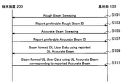
- the combination of the rough beam and the accurate beam described above in (efficiency of beam sweeping) is as follows.
- FIG. 11 is an explanatory view showing an example of a beam sweeping procedure of DL by the base station 100 and the terminal device 200.
- transmission sweeping using a rough beam is performed from the base station to the terminal apparatus (step S101).
- This transmission sweeping is performed by a sweeping pattern unique to the base station 100.
- transmission sweeping is also referred to as Base Station-specific or Cell Specific.
- the terminal device 200 reports the number of the rough beam desired for the own device to the base station 100 (step S103).
- the terminal device 200 determines, for example, whether it is the beam with the largest received power when determining the desired Rough beam.
- the base station 100 When the base station 100 receives the report of the rough beam number from the terminal device 200, the base station 100 performs transmission sweeping using the Accurate Beam corresponding to the rough beam (step S105).
- the transmission sweeping at this time may be a case of a sweeping pattern unique to the terminal device 200 specially prepared for the terminal device 200.
- the base station 100 may notify which terminal device 200 to monitor which part.
- the transmission sweeping pattern itself is the one specific to the terminal device 200 (UE Specific).
- the setting of the transmission sweeping pattern can be said to be specific to the terminal device 200 (UE Specific).
- the terminal device 200 reports the number of the Accurate beam desired for the own device to the base station 100 (step S107).
- the terminal device 200 may determine, for example, whether it is the beam with the largest received power when determining the desired Accurate beam.
- the base station 100 When receiving the report of the Accurate beam number from the terminal device 200, the base station 100 transmits DL user data to the terminal device 200 using the Accurate beam (step S109). Then, when Channel Reciprocity is secured, the base station 100 receives UL user data from the terminal device 200 using the same Accurate beam as the Accurate beam at the time of transmission for reception from the terminal device 200. (Step S111).
- a rough beam may be set commonly to cells and base stations, and a plurality of terminal devices may be shared. In this case, each terminal device may monitor the rough beam. Also, the Accurate beam may be customized and provided individually for each terminal device. Also, as another example, a common accurate beam may be provided to a plurality of terminal devices. In this case, by designating which beam is to be monitored for each terminal device, it becomes possible to provide necessary beams for each terminal device.
- the DL CQI acquisition is a CQI (Channel Quality Indicator) feedback that uses what modulation scheme and coding rate the terminal device side wants to use for DL Data Transmission as a base station, and is a terminal device using UL-based feedback.
- CQI Channel Quality Indicator
- the terminal apparatus can determine a desired CQI (combination of modulation scheme and individual coding rate).
- the desired transmission beam at the base station side is determined, and in the CSI acquisition procedure, the CQI is determined at the terminal device side, and this is determined from the terminal device by CSI feedback. It is necessary to notify the base station.
- Beam Recovery In the present disclosure, beam recovery is to find out and use a new different beam because the beam between the base station and the terminal device can not be used for some reason.
- the reasons for the need for Beam Recovery are generally as follows.
- Blocking is complete loss of signal, and it is difficult to hope for the return of communication with the same beam unless the obstacles, cars and people, are not intervened. Even if the base station slightly changes the frequency at which data is transmitted, there is a high possibility that it is difficult to transmit and receive beams using the direction of the obstacle in all nearby frequency bands. Even in the time direction, there is a high possibility that communication will be difficult for several seconds until no obstacle is present.
- interference does not always occur at all time and frequency resources. Therefore, interference will not occur when other base stations or other terminals stop transmission.
- LTE Long Term Evolution
- one beam provided control signals and user data. Unlike this, in 5G, since it is possible to transmit and receive control signals and user data using a plurality of beams, it is necessary to improve the resistance to interference in consideration of this characteristic.
- the base station in the case of blocking, is basically required to change the beam. In order to change the beam, it is necessary to return quickly, that is, to identify a new beam as soon as possible.
- beam communication is used for control of a car, control of a drone, control of a remote medical device, etc. which are required to continuously communicate with low delay.
- PDCCH Physical Downlink Control Channel
- the PDCCH is a channel on which Downlink control signals are transmitted, and is more important than user data. Therefore, it is desirable to quickly recover from the situation where the terminal device can not receive the control signal.
- PDSCH Physical Downlink Shard Channel
- PDSCH Physical Downlink Shard Channel
- the PUSCH is a channel transmitted by the Uplink control signal, and is as important as the Downlink control signal.
- PUSCH Physical Uplink Shared Channel
- PDSCH is a channel through which uplink user data is transmitted.
- Beam This is a beam used between the base station and the terminal device.
- the base station determines a beam and transmits and receives Uplink and Downlink using the beam. Therefore, if the used beam itself can not be used, the base station needs to find a new appropriate beam as soon as possible. After all, the first thing to recover is the beam. This is because it is difficult to recover only the PDCCH while the beam is not recovered. That is, among the five mentioned so far, it can be said that beam restoration is the most important.
- the present disclosure proposes an example of a technique that enables quick recovery of communication between a base station and a terminal device even when blocking or beam quality degradation occurs. Specifically, the present disclosure proposes an example of a technique that makes it possible to quickly find a new beam link in the beam recovery procedure.
- the candidate for beam for backup is reported in addition to the candidate for optimal beam which the terminal device wants to use for communication with the base station. It is also possible to provide redundancy in the choice of beams. However, if only K (K is an integer of 2 or more) beams are reported, the base station mainly uses beams for communication with the terminal (that is, the terminal communicates with the base station). It is difficult to distinguish between the beam you want to use for communication and the beam notified for backup.
- the terminal device 200 when performing beam reporting to the base station 100, the terminal device 200 designates and reports a backup beam. In other words, the terminal device 200 distinguishes and reports the beam for backup from the beam candidate which it wants to use for communication with a base station.
- the backup beam corresponds to, for example, a beam that can be used in place of a beam used in priority to communication between the base station 100 and the terminal device 200 (for example, a beam that the terminal device wants to use).
- the method of specifying a backup beam is not particularly limited. That is, the backup beam may be designated explicitly (Explicit) or may be implicitly designated (Implicit).
- FIG. 12 is a sequence diagram showing an example of a flow of a series of processes of the communication system according to the present embodiment.
- the base station 100 (notification unit 155) notifies the terminal device 200 located within its own communication range (within the cell) of information on the setting of beam sweeping (S201). Also, the base station 100 (notification unit 155) notifies the terminal device 200 of information related to the setting of beam reporting (S203). Then, the base station 100 (communication control unit 151) performs beam sweeping (S205). Specifically, base station 100 emits beams in a time division manner in each of a plurality of directions.
- the terminal device 200 receives a beam transmitted by the base station 100 in a plurality of directions in a time division manner based on the information notified from the base station 100.
- the terminal device 200 (selection unit 245) measures the quality of each beam (for example, RSRP: Reference Signal Received Power), and according to the measurement result, a beam used in preference to communication with the base station 100 (hereinafter referred to as , Also referred to as “main beam”, and a beam for backup that can be used instead of the beam (hereinafter also referred to as “backup beam”).
- RSRP Reference Signal Received Power
- the terminal device 200 notifies the base station 100 of information on the selected main beam (that is, the beam that the terminal device 200 wishes to use) and the backup beam to the base station 100 (that is, Perform beam reporting).
- the terminal device 200 associates the ID (for example, the measurement result of RSRP) according to the measurement result of the quality of the beam with each of the selected main beam and backup beam ID.
- the ID may be notified to the base station 100 (S207).
- the beam associated with ID1 is selected as the main beam
- the beam associated with ID2 is selected as the backup beam.
- the base station 100 acquires, from the terminal device 200, a notification (report) on the main beam and the backup beam selected by the terminal device 200.
- the base station 100 (communication control unit 151) registers ID2 as the backup beam ID based on the notification from the terminal device 200 (S209). Then, the base station 100 (the communication control unit 151) transmits user data to the terminal device 200 using the beam associated with the ID 1 (S211).
- a beam registered as a backup beam ie, a beam associated with ID2
- communication between the base station 100 and the terminal device 200 using the main beam ie, a beam associated with ID1
- the main beam ie, a beam associated with ID1
- the base station 100 can continue communication using the registered backup beam without performing beam sweeping again.
- the main beam corresponds to an example of the "first beam”
- the backup beam corresponds to an example of the "second beam”.
- Modification 1 Then, the modification of the communication system concerning one embodiment of this indication is explained. Hereinafter, this modification is also referred to as "modification 1".
- FIG. 13 is a sequence diagram illustrating an example of a flow of a series of processes of the communication system according to the first modification. Specifically, FIG. 13 illustrates an example in the case where the base station 100 selectively controls whether to notify the terminal device 200 of information on a backup beam based on timer control. .
- the base station 100 notifies the terminal device 200 located within its own communication range (within the cell) of the information on the setting of beam sweeping (S251). Further, the base station 100 (notification unit 155) notifies the terminal device 200 of information on setting of beam reporting and information on setting of reporting of backup beam (S253). Then, the base station 100 (the communication control unit 151) performs beam sweeping (S255). Specifically, base station 100 emits beams in a time division manner in each of a plurality of directions.
- the terminal device 200 receives a beam transmitted by the base station 100 in a plurality of directions in a time division manner based on the information notified from the base station 100.
- the terminal device 200 (selection unit 245) measures the quality (for example, RSRP) of each beam, and selects the main beam and the backup beam according to the measurement result. Then, the terminal device 200 associates the ID (for example, the measurement result of RSRP) according to the measurement result of the quality of the beam with the ID of each of the selected main beam and backup beam, and then bases the ID. It notifies the station 100 (S257).
- the beam associated with ID1 is selected as the main beam
- the beam associated with ID2 is selected as the backup beam.
- the base station 100 acquires, from the terminal device 200, a notification (report) on the main beam and the backup beam selected by the terminal device 200.
- the base station 100 (communication control unit 151) registers ID2 as the ID of the backup beam based on the notification from the terminal device 200, and starts a timer (S259). Then, the base station 100 (the communication control unit 151) transmits user data to the terminal device 200 using the beam associated with the ID 1 (S261).
- the base station 100 (notification unit 155) notifies the terminal device 200 of information on the setting of beam reporting. At this time, the base station 100 does not notify the terminal device 200 about the information related to the setting of reporting of the backup beam (S263). Then, the base station 100 (the communication control unit 151) performs beam sweeping (S265).
- the terminal device 200 receives a beam transmitted by the base station 100 in a plurality of directions in a time division manner based on the information notified from the base station 100.
- the terminal device 200 (selection unit 245) measures the quality (for example, RSRP) of each beam, and selects the main beam according to the measurement result. At this time, the terminal device 200 does not select the backup beam based on the information notified from the base station 100. Then, the terminal device 200 (notification unit 247) associates the ID (for example, the measurement result of RSRP) according to the measurement result of the quality of the beam with the ID of the selected main beam, Notify the base station 100 (S267)
- the ID for example, the measurement result of RSRP
- the base station 100 (notification unit 155) notifies the terminal device 200 of the information on the setting of beam reporting and the information on the setting of reporting of the backup beam (S271). Then, the base station 100 (the communication control unit 151) performs beam sweeping (S273).
- the terminal device 200 receives a beam transmitted by the base station 100 in a plurality of directions in a time division manner based on the information notified from the base station 100.
- the terminal device 200 (selection unit 245) measures the quality (for example, RSRP) of each beam, and selects the main beam and the backup beam according to the measurement result. Then, the terminal device 200 associates the ID (for example, the measurement result of RSRP) according to the measurement result of the quality of the beam with the ID of each of the selected main beam and backup beam, and then bases the ID.
- the station 100 is notified (S275).
- the base station 100 When the base station 100 registers the backup beam based on the report from the terminal device 200 by the control as described above, the base station 100 determines that the backup beam is valid for a certain period of time by timer control. Then, when the expiration date of the timer has elapsed, the base station 100 causes the terminal device 200 to report on the backup beam again, and newly registers the backup beam. That is, the base station 100 performs control so as not to request the terminal device 200 for a report on the backup beam in a period in which the backup beam is effective. Such control can reduce the frequency of reporting on backup beams, and can reduce UL overhead due to the report as compared to reporting of backup beams each time beam sweeping is performed. Become.
- Modification 2 Subsequently, another modified example of the communication system according to an embodiment of the present disclosure will be described. In the following, this modification is also referred to as "modification 2".
- the terminal device 200 when the terminal device 200 performs beam reporting on the base station 100, the backup beam is also reported.
- the terminal device 200 sets a beam group including one or more backup beams (hereinafter also referred to as “backup beam group”), and reports the beam group to the base station 100.
- FIG. 14 is an explanatory diagram for describing an overview of the communication system according to the second modification.
- backup beam groups B101 to B103 are set.
- backup beam group B101 is set to include backup beams B101-1 to B101-3.
- backup beam group B102 is set to include backup beams B102-1 and B102-2.
- backup beam group B103 is set to include backup beams B103-1 to B103-3.
- each backup beam group be set so as to have low correlation with each other and to use the beams included in the other group as backups of the beams included in one group.
- the plurality of beams included in the same group may be beams exhibiting similar characteristics to one another.
- the base station it is possible for the base station to recognize that beams belonging to different backup groups are in a mutually available backup relationship. Therefore, backup may not be clearly indicated for each beam belonging to different backup groups. Of course, each beam belonging to different backup groups may be clearly indicated as backup.
- a method of classifying each beam into a backup group there is, for example, a method of classifying each of a plurality of beams into groups according to the direction of arrival of each beam when viewed from the terminal device 200.
- the terminal device 200 classifies each beam according to the direction in which each beam reaches itself (that is, the direction of arrival of the beam) based on the reception result of each beam, and each terminal according to the classification result.
- the beams may be grouped.
- the terminal device 200 may receive information on the direction in which each beam is transmitted (for example, information indicating how different the direction in which each beam is transmitted, etc.) or between each beam transmitted from the base station 100. It is preferable to obtain information such as the correlation value of H from the base station 100 in advance. As a result, for each of the received beams, the terminal device 200 can determine the backup beam according to the direction in which the beam is transmitted from the base station 100 when viewed from the base station 100.
- the terminal device 200 can also report the measurement result (for example, RSRP) of the quality of the beam to the base station 100. Also, the terminal device 200 may classify each beam according to the direction in which the beam is transmitted from the base station 100, and may group each beam according to the classification result.
- the measurement result for example, RSRP
- FIG. 15 is a sequence diagram illustrating an example of a flow of a series of processes of the communication system according to the second modification.
- the base station 100 (notification unit 155) notifies the terminal device 200 located within its own communication range (within the cell) of information on the setting of beam sweeping (S301). Also, the base station 100 (notification unit 155) notifies the terminal device 200 of information related to the setting of beam reporting (S303). Then, the base station 100 (communication control unit 151) performs beam sweeping (S305). Specifically, base station 100 emits beams in a time division manner in each of a plurality of directions.
- the terminal device 200 receives a beam transmitted by the base station 100 in a plurality of directions in a time division manner based on the information notified from the base station 100.
- the terminal device 200 selects a beam to be used as a main beam or a backup beam based on the reception result of each beam, and assigns each of the selected beams to a beam group.
- the terminal device 200 (notification unit 247) associates the information on the set beam group (for example, the ID of the beam group) with the beam report and notifies the base station 100 (S307).
- the set beam group for example, the ID of the beam group
- the base station 100 acquires, from the terminal device 200, a notification (a beam report) in which information on the beam group set by the terminal device 200 is associated.
- the base station 100 (the communication control unit 151) selects, as a main beam, a beam belonging to any one of beam groups set by the terminal device 200 based on a notification from the terminal device 200, for example, A beam belonging to another beam group is registered as a backup beam.
- a beam belonging to another beam group is registered as a backup beam.
- the base station 100 (the communication control unit 151) transmits user data to the terminal device 200 using the beam (that is, the beam selected as the main beam) belonging to the beam group 3 (S311).
- the backup beam group When the backup beam group is set according to the direction in which base station 100 transmits each beam, beams belonging to the same beam group arrive from different directions when viewed from terminal apparatus 200. It may appear as a beam. Similarly, when the backup beam group is set according to the arrival direction of each beam to the terminal device 200, beams belonging to the same beam group are transmitted in different directions when viewed from the base station 100. It may appear as a broken beam.
- a beam group when a beam group is set, only some of the one or more beams included in the beam group (for example, beams with better characteristics) may be used for communication.
- beam sweeping is performed in the backup beam group to be switched, so that some of the beams belonging to the backup beam group are selected as backup beams. It may be done.
- the range in which beam sweeping is performed is limited to the range of the backup beam group, the time required for processing can be shortened as compared to the case where beam sweeping is performed for the entire target. It becomes.
- Modification 3 Another modified example of the communication system according to an embodiment of the present disclosure will be described. Hereinafter, this modification is also referred to as "modification 3". In this modification, an example of control according to the blocking situation will be described.
- blocking occurs when an obstacle such as a person, a vehicle, or a building is interposed between the base station 100 and the terminal device 200, and between the base station 100 and the terminal device 200 due to the obstacle. It occurs when the communication (in other words, the beam) is blocked.
- the state of blocking differs depending on the positional relationship between the base station 100, the terminal device 200, and the obstacle.
- FIG. 16 is an explanatory diagram for describing an example of a blocking situation.
- an obstacle 310 is located in the vicinity of the terminal device 200, and the beam from the base station 100 is blocked by the obstacle 310.
- FIG. 17 is an explanatory diagram for describing another example of the state of blocking.
- an obstacle 310 is located in the vicinity of the base station 100, and the beam from the base station 100 is blocked by the obstacle 310.
- the beam to be held as a backup candidate is different.
- FIG. 18 is an explanatory diagram for describing an example of a beam selected according to the blocking situation, and an example in the case where an obstacle 310 is located in the vicinity of the terminal device 200 as shown in FIG. It shows.
- FIG. 18 illustrates an example of a beam that is reflected by a reflecting object 330 such as a building, and that comes from a direction different from the direction in which the obstacle 310 is located with respect to the terminal device 200. .
- FIG. 19 is an explanatory diagram for describing an example of a beam selected according to a blocking situation, and an example in the case where an obstacle 310 is located in the vicinity of the base station 100 as shown in FIG. It shows.
- the terminal apparatus 100 transmits a signal from the base station 100 in a direction different from the direction in which the obstacle 310 is located with respect to the base station 100, and reflects the light by the reflector 330 such as a building.
- An example of a beam reaching 200 is shown.
- the direction different from the beam used in the past It is desirable to select beam candidates coming from. It is to be noted that the beam to be selected at this time may be largely different in direction from the base station 100 to the previously used beam and not likely to be different from the previously used beam. Both can be assumed. This is because it is a viewpoint on the terminal device 200 side to the last.
- reception beam forming on the terminal device 200 side for receiving a more preferable beam is specified.
- reception beam forming on the terminal device 200 side for receiving a more preferable beam is specified.
- reception beam forming on the terminal device 200 side for receiving a more preferable beam is specified.
- reception beam forming on the terminal device 200 side for receiving a more preferable beam is specified.
- reception beam forming on the terminal device 200 side for receiving a more preferable beam is specified.
- reception beam from the base station 100 may be identified.
- the terminal device 200 may report the identified beam to the base station 100 as a back up beam from the viewpoint of the terminal device 200 (back up beams from UE perspective).
- the report on the backup beam from the viewpoint of the terminal device 200 corresponds to an example of the “first information”.
- a candidate beam to be transmitted in a direction different from the previously used beam as viewed from the base station 100 is selected as a backup beam. It is desirable to do. Note that the beam selected at this time may differ greatly from the direction in which the direction of arrival at the terminal 200 is from the beam previously used, and may not differ greatly from the beam previously used, Both can be assumed. This is because it is a point of view on the base station 100 side.
- the terminal device 200 first identifies a more preferable beam from each beam transmitted by the beam sweeping by the base station 100. Then, in the case of determining a backup beam, a beam that can be received with higher received power may be specified from among the specified beam and a beam with lower correlation from the viewpoint of the base station 100. In this case, on the side of terminal apparatus 200, it is determined whether or not the correlation between beams transmitted from base station 100 (that is, the correlation between beams from the viewpoint of base station 100) is low. A mechanism is needed. Therefore, for example, the base station 100 starts beam sweeping of information such as the direction of each beam transmitted from the base station 100, the antenna weight used for the beams, and the correlation value between the transmitted beams.
- the terminal device 200 can select, from the base station 100, a candidate for a beam to be transmitted in a direction different from the beam used before.
- the terminal device 200 may report the identified beam to the base station 100 as a back up beam from the base station 100 as a back up beam from the base station perspective.
- the report on the backup beam from the viewpoint of the base station 100 corresponds to an example of the “second information”.
- a backup beam for example, a backup beam (back up beams from base station perspective) in the case of blocking occurring in the vicinity of the base station 100 and a backup beam in the case of blocking in the vicinity of the terminal device 200 ( The base station 100 may be notified of both back up beams from UE perspective).
- the terminal device 200 may request the base station 100 to perform beam recovery (blocking notification). At this time, it may be assumed that it is difficult for the base station 100 to determine whether blocking occurred near the base station 100 or near the terminal device 200. Therefore, for example, the base station 100 transmits, to the terminal device 200, backup beams from the viewpoints of the base station 100 and the terminal device 200 registered as backup, and a report corresponding to the evaluation result of the beams is transmitted. It may be acquired from the terminal device 200. In this case, for example, the base station 100 may use a beam with a better evaluation result from the terminal device 200 for recovering communication with the terminal device 200.
- the above is merely an example, and the operation relating to beam recovery is not necessarily limited.
- the base station 100 can recognize the positional relationship between the base station 100, the terminal device 200, and the obstacle, the base station 100 and the terminal device 200 can be selected according to the recognition result.
- a backup beam according to at least one of the aspects may be used for communication recovery.
- FIG. 20 is a sequence diagram illustrating an example of a flow of a series of processes of the communication system according to the third modification.
- the base station 100 notifies the terminal device 200 located within its own communication range (within the cell) of the information on the setting of beam sweeping (S351). Also, the base station 100 (notification unit 155) notifies the terminal device 200 of information (Base station beam information) on each beam transmitted from the base station 100 (S353). Also, the base station 100 (notification unit 155) notifies the terminal device 200 of information related to the setting of beam reporting (S355). Then, the base station 100 (the communication control unit 151) performs beam sweeping (S357). Specifically, base station 100 emits beams in a time division manner in each of a plurality of directions.
- the terminal device 200 receives a beam transmitted by the base station 100 in a plurality of directions in a time division manner based on the information notified from the base station 100.
- the terminal device 200 selects a beam (that is, a main beam) to be used prior to transmission of user data based on the reception result of each beam, and uses information on the selected beam as a beam report. It associates and notifies the base station 100 (S359).
- the terminal device 200 identifies a back-up beam (back up beams from UE perspective) from the terminal device 200, associates information on the beam with the beam report, and notifies the base station 100 (S361).
- the terminal device 200 identifies a back-up beam from the base station 100 in terms of back-up beams (base stations perspective), associates information on the beam with the beam report, and notifies the base station 100 (S363).
- the base station 100 Based on the information (beam report) notified from the terminal device 200, the base station 100 (information acquisition unit 243) uses a back up beam from the viewpoint of the terminal device 200 (back up beams from UE perspective) and the base station 100. Back up beams from the perspective of the base station perspective and are registered (S365). Also, the base station 100 (the communication control unit 151) transmits user data to the terminal device 200 based on the information notified from the terminal device 200, for example, using the beam selected as the main beam (S367) .
- the terminal device 200 (notification unit 247) makes a request (Blocking notification / beam recovery request) related to beam recovery to the base station 100 (S369).
- the base station 100 (the communication control unit 151) has registered as a backup, a back-up beam from the viewpoint from the terminal device 200 (back up beams from UE perspective) and a back-up beam (from the base station 100). Each of the back up beams from the base station perspective is transmitted to the terminal device 200 (S371, S373).
- the terminal device 200 (communication control unit 241) receives the backup beam transmitted from the base station 100 from the viewpoints of the terminal device 200 and the base station 100. Then, the terminal device 200 (notification unit 247) reports on both backup beams from the viewpoints of the terminal device 200 and the base station 100 (S375).
- the base station 100 can restore communication with the terminal device 200 using a more preferable beam among the backup beams from the viewpoints of the terminal device 200 and the base station 100.
- the base station 100 may re-search for available beams for recovery by normal beam sweeping. About this operation, it is the same not only to this modification but the example concerning the embodiment mentioned above and other modifications, for example.
- Modification 4 Another modified example of the communication system according to an embodiment of the present disclosure will be described. Hereinafter, this modification is also referred to as "Modification 4". In this modification, an example of control assuming use of a partial frequency band (partial band) will be described. In the following description, “frequency band” is also simply referred to as “band”.
- FIG. 21 is an explanatory diagram for describing an outline of a partial band in 5G.
- a plurality of partial bands (band width parts) are prepared in one component carrier (Component Carrier).
- Component Carrier component carrier
- These partial bands may be used for a variety of applications, such as being used for high speed download and sometimes for transmitting low latency traffic.
- separate partial bands may be used, each with a different subcarrier spacing.
- bands having different subcarrier spacing may be used for each feature.
- interval 15 kHz, 30 kHz, 60 kHz etc. are mentioned, for example.
- different numerologies may be applied to partial bands.
- partial band 1 and partial band 2 are set as partial bands.
- normal beam sweeping is performed for both partial band 1 and partial band 2.
- backup beams may be set for each of partial band 1 and partial band 2, and in this case, both of partial band 1 and partial band 2 from terminal apparatus 200 to base station 100 may be set. Information about the backup beam (report) is notified.
- registration of backup beams is performed for each of the partial band 1 and the partial band 2.
- the base station 100 when a request (Beam recovery request) related to beam recovery is performed from the terminal device 200 to the base station 100, the base station 100 is a backup beam corresponding to each of the partial band 1 and the partial band 2. May be transmitted to the terminal device 200 by time division multiplexing or frequency multiplexing. At this time, the base station 100 may transmit backup beams corresponding to each of the partial band 1 and the partial band 2 to be multiplexed as one configuration. As a result, for example, the terminal device 200 can simultaneously evaluate the backup beams corresponding to each of the partial band 1 and the partial band 2, and can also shorten the time required for beam restoration.
- Beam recovery request Beam recovery request
- FIG. 22 is a sequence diagram illustrating an example of a flow of a series of processes of the communication system according to the fourth modification.
- partial band 1 and partial band 2 are set as partial bands.
- the base station 100 notifies the terminal device 200 located within its own communication range (within the cell) of information on the setting of beam sweeping (S401). Also, the base station 100 (notification unit 155) notifies the terminal device 200 of information on the setting of beam reporting and the setting of backup beam reporting (S403).
- the base station 100 (communication control unit 151) performs beam sweeping. At this time, the base station 100 individually performs beam sweeping on each of the partial band 1 and the partial band 2.
- the base station 100 (communication control unit 151) performs beam sweeping on the partial band 1 (S405).
- the terminal device 200 receives a beam transmitted by the base station 100 in time division toward each of a plurality of directions using the partial band 1 based on the information notified from the base station 100. .
- the terminal device 200 (selection unit 245) performs notification of information (Beam report) on the main beam and notification of information (Backup beam report) on the backup beam for the partial band 1 based on the reception result of each beam. (S407).
- the base station 100 (communication control unit 151) performs beam sweeping on the partial band 2 (S409).
- the terminal device 200 (communication control unit 241) receives a beam transmitted by the base station 100 in time division toward each of a plurality of directions using the partial band 2 based on the information notified from the base station 100. .
- the terminal device 200 (selection unit 245) performs notification of information (Beam report) on the main beam and notification of information (Backup beam report) on the backup beam for the partial band 2 based on the reception result of each beam. (S411).
- the base station 100 (information acquisition unit 243) registers backup beams for each of partial band 1 and partial band 2 based on the information notified from the terminal device 200 for each of partial band 1 and partial band 2 (S413).
- the base station 100 (communication control unit 151) transmits each of the backup beam corresponding to partial band 1 and the backup beam corresponding to partial band 2 registered as backup to the terminal device 200 (S417) , S419). At this time, as described above, the base station 100 may transmit the backup beams corresponding to the partial band 1 and the partial band 2 as one configuration by time-division multiplexing or frequency division multiplexing.
- the terminal device 200 (communication control unit 241) receives the backup beam corresponding to each of the partial band 1 and the partial band 2 transmitted from the base station 100. Then, the terminal device 200 (notification unit 247) reports on both backup beams corresponding to the partial band 1 and the partial band 2 (S421). As a result, the base station 100 can restore communication with the terminal device 200 using a more suitable beam for each of the partial band 1 and the partial band 2.
- the base station 100 transmits user data to the terminal device 200 using the backup beam corresponding to the partial band 1 (S423).
- the base station 100 transmits user data to the terminal device 200 using the backup beam corresponding to the partial band 2 (S425).
- the terminal device 200 may notify the base station 100 of requesting recovery of only the partial band 1 by a beam recovery request. . Also, in this case, the base station 100 may execute the process related to beam restoration only for the partial band 1 in response to a request from the terminal device 200.
- a backup beam can be registered for each component carrier, and communication between the base station 100 and the terminal device 200 can be restored for each component carrier using the registered backup beam.
- the priority may be notified from the base station 100 to the terminal device 200, for example. Further, as another example, the priority may be defined in advance by a standard or the like. Further, as another example, information on a desired priority may be notified from the terminal device 200 to the base station 100. Further, the priority may be set between bands or may be set between backup beams registered for each band.
- FIG. 23 is a sequence diagram illustrating an example of a flow of a series of processes of the communication system according to the fifth modification.
- partial band 1 and partial band 2 are set as partial bands.
- the base station 100 and the terminal device 200 execute a procedure related to backup beam registration as indicated by reference symbols S451 to S463.
- the processes indicated by reference numerals S451 to S463 are substantially the same as the processes indicated by reference numerals S401 to S413 in the example shown in FIG. 22, and thus detailed description will be omitted.
- the terminal device 200 notifies the base station 100 of a request related to the setting of the priority between partial bands for beam restoration (S465).
- the base station 100 notifies information on the priority set in partial bands (S467).
- S467 In the example illustrated in FIG. 23, it is assumed that higher priority than partial band 1 is set for partial band 2. Specifically, it is assumed that the highest priority (1st priority) is set for partial band 2 and the second highest priority (2nd priority) is set for partial band 1 Do.
- the terminal device 200 (notification unit 247) makes a request (Blocking notification / beam recovery request) related to beam recovery to the base station 100 (S469).
- the base station 100 performs beam recovery on the partial band 2 for which the highest priority (1st prioritization) is set. Specifically, the base station 100 (the communication control unit 151) transmits the backup beam corresponding to the partial band 2 to the terminal device 200 (S471). The terminal device 200 (communication control unit 241) receives the backup beam corresponding to partial band 2 transmitted from the base station 100. Also, the terminal device 200 (notification unit 247) reports on the backup beam corresponding to the partial band 2 (S473). As a result, the base station 100 can restore communication with the terminal device 200 using the beam more suitable for the partial band 2. Then, for the partial band 2, the base station 100 transmits user data to the terminal apparatus 200 using the backup beam corresponding to the partial band 2 (S475).
- the base station 100 performs beam recovery for partial band 1 in which the second highest priority (2nd prioritization) is set for partial band 2.
- the base station 100 (the communication control unit 151) transmits the backup beam corresponding to the partial band 1 to the terminal device 200 (S477).
- the terminal device 200 (communication control unit 241) receives the backup beam corresponding to partial band 1 transmitted from the base station 100.
- the terminal device 200 (notification unit 247) reports on the backup beam corresponding to the partial band 1 (S479).
- the base station 100 can restore communication with the terminal device 200 using a more suitable beam for the partial band 1.
- the base station 100 transmits user data to the terminal device 200 using the backup beam corresponding to the partial band 1 (S481).
- the base station 100 preferentially restores a beam with a higher priority band. This makes it possible to further shorten the recovery time of the communication to which higher priority is set.
- beam recovery may be performed only for some two or more bands among a plurality of partial bands in which backup beams are registered.
- bands to which a higher priority is set may be controlled to be a target of beam recovery with higher priority.
- Modification 6 Modification 6
- CSI acquisition it is more desirable that CSI acquisition be performed separately for each partial band. This is due to the fact that channel characteristics may differ for each partial band.
- the procedure for searching for a more suitable beam in the beam management procedure there are often no significant differences in the beams used in each partial band. This is because beam forming used in 5 G forms a beam by concentrating energy in a specific direction, so that only a slight difference in frequency causes a large change in the direction in which the beam is directed. It is because there is not. Due to such characteristics, for example, even if a more preferable beam is selected per partial band for normal times, a common beam is registered for beams for beam recovery in emergency. The case where it is good to do may also be assumed.
- FIG. 24 is a sequence diagram illustrating an example of a flow of a series of processes of the communication system according to the sixth modification.
- partial band 1 and partial band 2 are set as partial bands.
- the base station 100 (notification unit 155) notifies the terminal device 200 located within its own communication range (within the cell) of information on the setting of beam sweeping (S501). Subsequently, the base station 100 (communication control unit 151) performs beam sweeping. At this time, the base station 100 individually performs beam sweeping on each of the partial band 1 and the partial band 2.
- the base station 100 (communication control unit 151) performs beam sweeping on the partial band 1 (S503).
- the terminal device 200 (communication control unit 241) receives a beam transmitted by the base station 100 in time division toward each of a plurality of directions using the partial band 1 based on the information notified from the base station 100. .
- the terminal device 200 (selection unit 245) notifies, based on the reception result of each beam, information (Beam report) on the main beam for partial band 1 (S505).
- the base station 100 performs beam sweeping on the partial band 2 (S507).
- the terminal device 200 receives a beam transmitted by the base station 100 in time division toward each of a plurality of directions using the partial band 2 based on the information notified from the base station 100. .
- the terminal device 200 (selection unit 245) notifies, based on the reception result of each beam, information (Beam report) on the main beam for the partial band 2 (S509).
- the terminal device 200 based on the reception result of each beam transmitted for each of partial band 1 and partial band 2, the terminal device 200 (selection unit 245), information on a backup beam common to partial band 1 and partial band 2 (Backup beam report) ) Is notified (S511).
- the base station 100 (the information acquisition unit 243) registers a common backup beam in the partial band 1 and the partial band 2 based on the information commonly notified to the partial band 1 and the partial band 2 from the terminal device 200 (S513) .
- the terminal device 200 (notification unit 247) makes a request (Blocking notification / beam recovery request) related to beam recovery to the base station 100 (S515).
- the base station 100 (communication control unit 151) transmits a backup beam common to the partial band 1 and the partial band 2 to the terminal device 200 (S517).
- the terminal device 200 receives a backup beam common to the partial band 1 and the partial band 2 transmitted from the base station 100.
- the terminal device 200 (notification unit 247) reports on the received backup beam (S473).
- the base station 100 can restore communication with the terminal device 200 using a more suitable beam for the partial band 1.
- the base station 100 transmits user data to the terminal apparatus 200 using the backup beam common to the partial band 1 and the partial band 2 for the partial band 1 (S521).
- the base station 100 (communication control unit 151) transmits a backup beam common to the partial band 1 and the partial band 2 to the terminal device 200 (S523).
- the terminal device 200 receives a backup beam common to the partial band 1 and the partial band 2 transmitted from the base station 100.
- the terminal device 200 (notification unit 247) reports on the received backup beam (S525).
- the base station 100 can restore communication with the terminal device 200 using the beam more suitable for the partial band 2.
- the base station 100 transmits user data to the terminal apparatus 200 using the backup beam common to the partial band 1 and the partial band 2 for the partial band 2 (S527).
- the base station 100 may be realized as any type of eNB (evolved Node B) such as a macro eNB or a small eNB.
- the small eNB may be an eNB that covers a cell smaller than a macro cell, such as a pico eNB, a micro eNB, or a home (femto) eNB.
- the base station 100 may be implemented as another type of base station such as a Node B or a BTS (Base Transceiver Station).
- the base station 100 may include a main body (also referred to as a base station apparatus) that controls wireless communication, and one or more RRHs (Remote Radio Heads) disposed at a location different from the main body. Also, various types of terminals to be described later may operate as the base station 100 by temporarily or semipermanently executing the base station function. Furthermore, at least some components of base station 100 may be realized in a base station apparatus or a module for a base station apparatus.
- the terminal device 200 may be a smartphone, a tablet PC (Personal Computer), a notebook PC, a portable game terminal, a mobile terminal such as a mobile / dongle type mobile router or a digital camera, or an on-vehicle terminal such as a car navigation device. May be realized as The terminal device 200 may be realized as a terminal (also referred to as a machine type communication (MTC) terminal) that performs M2M (Machine To Machine) communication. Also, the terminal device 200 may be realized as a so-called low cost terminal such as an MTC terminal, an eMTC terminal, and an NB-IoT terminal. Furthermore, at least part of the components of the terminal device 200 may be realized in a module mounted on these terminals (for example, an integrated circuit module configured with one die).
- MTC machine type communication
- M2M Machine To Machine
- the terminal device 200 may be realized as a so-called low cost terminal such as an MTC terminal, an eMTC terminal, and an NB-IoT terminal.
- FIG. 25 is a block diagram illustrating a first example of a schematic configuration of an eNB to which the technology according to the present disclosure may be applied.
- the eNB 800 has one or more antennas 810 and a base station apparatus 820. Each antenna 810 and the base station apparatus 820 may be connected to each other via an RF cable.
- Each of the antennas 810 has a single or a plurality of antenna elements (for example, a plurality of antenna elements constituting a MIMO antenna), and is used for transmission and reception of radio signals by the base station apparatus 820.
- the eNB 800 may have a plurality of antennas 810 as illustrated in FIG. 25, and the plurality of antennas 810 may correspond to, for example, a plurality of frequency bands used by the eNB 800.
- FIG. 25 illustrates an example in which the eNB 800 has a plurality of antennas 810, the eNB 800 may have a single antenna 810.
- the base station apparatus 820 includes a controller 821, a memory 822, a network interface 823 and a wireless communication interface 825.
- the controller 821 may be, for example, a CPU or a DSP, and operates various functions of the upper layer of the base station device 820. For example, the controller 821 generates a data packet from data in the signal processed by the wireless communication interface 825, and transfers the generated packet through the network interface 823. The controller 821 may generate a bundled packet by bundling data from a plurality of baseband processors and transfer the generated bundled packet. Also, the controller 821 is a logic that executes control such as radio resource management (Radio Resource Control), radio bearer control (Radio Bearer Control), mobility management (Mobility Management), admission control (Admission Control), scheduling (Scheduling), etc. Function may be provided.
- Radio Resource Control Radio Resource Control
- Radio Bearer Control Radio Bearer Control
- Mobility Management Mobility Management
- Admission control Admission Control
- scheduling scheduling
- the control may be performed in cooperation with neighboring eNBs or core network nodes.
- the memory 822 includes a RAM and a ROM, and stores programs executed by the controller 821 and various control data (eg, terminal list, transmission power data, scheduling data, etc.).
- the network interface 823 is a communication interface for connecting the base station device 820 to the core network 824.
- the controller 821 may communicate with core network nodes or other eNBs via the network interface 823.
- the eNB 800 and the core network node or another eNB may be connected to each other by a logical interface (for example, an S1 interface or an X2 interface).
- the network interface 823 may be a wired communication interface or a wireless communication interface for a wireless backhaul.
- the network interface 823 may use a higher frequency band for wireless communication than the frequency band used by the wireless communication interface 825.
- the wireless communication interface 825 supports any cellular communication scheme such as LTE (Long Term Evolution) or LTE-Advanced, and provides a wireless connection to a terminal located in the cell of the eNB 800 via the antenna 810.
- the wireless communication interface 825 may typically include a baseband (BB) processor 826 and RF circuitry 827 and the like.
- the BB processor 826 may perform, for example, coding / decoding, modulation / demodulation, multiplexing / demultiplexing, etc., and each layer (eg, L1, medium access control (MAC), radio link control (RLC), and PDCP). Perform various signal processing (Packet Data Convergence Protocol).
- the BB processor 826 may have some or all of the logical functions described above instead of the controller 821.
- the BB processor 826 may be a memory that stores a communication control program, a processor that executes the program, and a module including related circuits, and the function of the BB processor 826 can be changed by updating the program. Good.
- the module may be a card or a blade inserted into a slot of the base station apparatus 820, or may be a chip mounted on the card or the blade.
- the RF circuit 827 may include a mixer, a filter, an amplifier, and the like, and transmits and receives a wireless signal through the antenna 810.
- the wireless communication interface 825 may include a plurality of BB processors 826 as illustrated in FIG. 25, and the plurality of BB processors 826 may correspond to, for example, a plurality of frequency bands used by the eNB 800.
- the wireless communication interface 825 may include a plurality of RF circuits 827 as illustrated in FIG. 25, and the plurality of RF circuits 827 may correspond to, for example, a plurality of antenna elements.
- FIG. 25 shows an example in which the wireless communication interface 825 includes a plurality of BB processors 826 and a plurality of RF circuits 827, the wireless communication interface 825 includes a single BB processor 826 or a single RF circuit 827. May be.
- one or more components included in the processing unit 150 described with reference to FIG. , And may be implemented in the wireless communication interface 825. Alternatively, at least a part of these components may be implemented in the controller 821. As one example, the eNB 800 may be equipped with a module including a part (for example, the BB processor 826) or all of the wireless communication interface 825 and / or the controller 821 and one or more components may be implemented in the module. Good.
- the module stores a program for causing the processor to function as the one or more components (in other words, a program for causing the processor to execute the operation of the one or more components). You may run the program.
- a program for causing a processor to function as the one or more components may be installed in the eNB 800, and the wireless communication interface 825 (for example, the BB processor 826) and / or the controller 821 may execute the program.
- the eNB 800, the base station apparatus 820 or the module may be provided as an apparatus including the one or more components, and a program for causing a processor to function as the one or more components is provided. May be Moreover, the readable recording medium which recorded the said program may be provided.
- the wireless communication unit 120 described with reference to FIG. 2 may be implemented in the wireless communication interface 825 (for example, the RF circuit 827).
- the antenna unit 110 may be mounted on the antenna 810.
- the network communication unit 130 may be implemented in the controller 821 and / or the network interface 823.
- the storage unit 140 may be implemented in the memory 822.
- FIG. 26 is a block diagram illustrating a second example of a schematic configuration of an eNB to which the technology of the present disclosure may be applied.
- the eNB 830 includes one or more antennas 840, a base station device 850, and an RRH 860. Each antenna 840 and RRH 860 may be connected to each other via an RF cable. Also, the base station device 850 and the RRH 860 may be connected to each other by a high speed line such as an optical fiber cable.
- Each of the antennas 840 has a single or a plurality of antenna elements (for example, a plurality of antenna elements constituting a MIMO antenna), and is used for transmission and reception of radio signals by the RRH 860.
- the eNB 830 may have a plurality of antennas 840 as shown in FIG. 26, and the plurality of antennas 840 may correspond to, for example, a plurality of frequency bands used by the eNB 830. Note that although FIG. 26 shows an example in which the eNB 830 has a plurality of antennas 840, the eNB 830 may have a single antenna 840.
- the base station device 850 includes a controller 851, a memory 852, a network interface 853, a wireless communication interface 855, and a connection interface 857.
- the controller 851, the memory 852 and the network interface 853 are similar to the controller 821, the memory 822 and the network interface 823 described with reference to FIG. 25.
- the wireless communication interface 855 supports any cellular communication scheme such as LTE or LTE-Advanced, and provides a wireless connection to terminals located in a sector corresponding to the RRH 860 via the RRH 860 and the antenna 840.
- the wireless communication interface 855 may typically include a BB processor 856 or the like.
- the BB processor 856 is similar to the BB processor 826 described with reference to FIG. 25 except that it is connected to the RF circuit 864 of the RRH 860 via the connection interface 857.
- the wireless communication interface 855 includes a plurality of BB processors 856 as shown in FIG. 25, and the plurality of BB processors 856 may correspond to, for example, a plurality of frequency bands used by the eNB 830.
- FIG. 26 shows an example in which the wireless communication interface 855 includes a plurality of BB processors 856, the wireless communication interface 855 may include a single BB processor 856.
- connection interface 857 is an interface for connecting the base station device 850 (wireless communication interface 855) to the RRH 860.
- the connection interface 857 may be a communication module for communication on the high-speed line that connects the base station device 850 (wireless communication interface 855) and the RRH 860.
- the RRH 860 also includes a connection interface 861 and a wireless communication interface 863.
- connection interface 861 is an interface for connecting the RRH 860 (wireless communication interface 863) to the base station device 850.
- the connection interface 861 may be a communication module for communication on the high speed line.
- the wireless communication interface 863 transmits and receives a wireless signal via the antenna 840.
- the wireless communication interface 863 may typically include an RF circuit 864 and the like.
- the RF circuit 864 may include a mixer, a filter, an amplifier, and the like, and transmits and receives wireless signals via the antenna 840.
- the wireless communication interface 863 may include a plurality of RF circuits 864 as illustrated in FIG. 26, and the plurality of RF circuits 864 may correspond to, for example, a plurality of antenna elements.
- FIG. 26 illustrates an example in which the wireless communication interface 863 includes a plurality of RF circuits 864, the wireless communication interface 863 may include a single RF circuit 864.
- the eNB 830 illustrated in FIG. 26 one or more components (at least one of the communication control unit 151, the information acquisition unit 153, and the notification unit 155) included in the processing unit 150 described with reference to FIG. , Wireless communication interface 855 and / or wireless communication interface 863. Alternatively, at least a part of these components may be implemented in the controller 851. As one example, the eNB 830 mounts a module including a part (for example, the BB processor 856) or all of the wireless communication interface 855 and / or the controller 851, and one or more components may be implemented in the module Good.
- the module stores a program for causing the processor to function as the one or more components (in other words, a program for causing the processor to execute the operation of the one or more components). You may run the program.
- a program for causing a processor to function as the one or more components may be installed in the eNB 830, and the wireless communication interface 855 (for example, the BB processor 856) and / or the controller 851 may execute the program.
- the eNB 830, the base station device 850, or the module may be provided as an apparatus including the one or more components, and a program for causing a processor to function as the one or more components is provided. May be Moreover, the readable recording medium which recorded the said program may be provided.
- the wireless communication unit 120 described with reference to FIG. 2 may be implemented in the wireless communication interface 863 (for example, the RF circuit 864).
- the antenna unit 110 may be mounted on the antenna 840.
- the network communication unit 130 may be implemented in the controller 851 and / or the network interface 853.
- the storage unit 140 may be implemented in the memory 852.
- FIG. 27 is a block diagram illustrating an example of a schematic configuration of a smartphone 900 to which the technology according to the present disclosure may be applied.
- the smartphone 900 includes a processor 901, a memory 902, a storage 903, an external connection interface 904, a camera 906, a sensor 907, a microphone 908, an input device 909, a display device 910, a speaker 911, a wireless communication interface 912, one or more antenna switches 915 , One or more antennas 916, a bus 917, a battery 918 and an auxiliary controller 919.
- the processor 901 may be, for example, a CPU or a SoC (System on Chip), and controls functions of an application layer and other layers of the smartphone 900.
- the memory 902 includes a RAM and a ROM, and stores programs and data to be executed by the processor 901.
- the storage 903 may include a storage medium such as a semiconductor memory or a hard disk.
- the external connection interface 904 is an interface for connecting an external device such as a memory card or a USB (Universal Serial Bus) device to the smartphone 900.
- the camera 906 includes an imaging element such as, for example, a charge coupled device (CCD) or a complementary metal oxide semiconductor (CMOS), and generates a captured image.
- the sensor 907 may include, for example, a sensor group such as a positioning sensor, a gyro sensor, a geomagnetic sensor, and an acceleration sensor.
- the microphone 908 converts audio input to the smartphone 900 into an audio signal.
- the input device 909 includes, for example, a touch sensor that detects a touch on the screen of the display device 910, a keypad, a keyboard, a button, a switch, or the like, and receives an operation or information input from the user.
- the display device 910 has a screen such as a liquid crystal display (LCD) or an organic light emitting diode (OLED) display, and displays an output image of the smartphone 900.
- the speaker 911 converts an audio signal output from the smartphone 900 into an audio.
- the wireless communication interface 912 supports any cellular communication scheme such as LTE or LTE-Advanced to perform wireless communication.
- the wireless communication interface 912 may typically include a BB processor 913, an RF circuit 914, and the like.
- the BB processor 913 may perform, for example, encoding / decoding, modulation / demodulation, multiplexing / demultiplexing, etc., and perform various signal processing for wireless communication.
- the RF circuit 914 may include a mixer, a filter, an amplifier, and the like, and transmits and receives a wireless signal through the antenna 916.
- the wireless communication interface 912 may be a one-chip module in which the BB processor 913 and the RF circuit 914 are integrated.
- the wireless communication interface 912 may include a plurality of BB processors 913 and a plurality of RF circuits 914 as shown in FIG. Although FIG. 27 shows an example in which the wireless communication interface 912 includes a plurality of BB processors 913 and a plurality of RF circuits 914, the wireless communication interface 912 includes a single BB processor 913 or a single RF circuit 914. May be.
- the wireless communication interface 912 may support other types of wireless communication systems, such as a near field communication system, a near field communication system, or a wireless local area network (LAN) system.
- a BB processor 913 and an RF circuit 914 for each wireless communication scheme may be included.
- Each of the antenna switches 915 switches the connection destination of the antenna 916 among a plurality of circuits (for example, circuits for different wireless communication systems) included in the wireless communication interface 912.
- Each of the antennas 916 has a single or a plurality of antenna elements (for example, a plurality of antenna elements constituting a MIMO antenna), and is used for transmission and reception of a wireless signal by the wireless communication interface 912.
- the smartphone 900 may have a plurality of antennas 916 as shown in FIG. Although FIG. 27 illustrates an example in which the smartphone 900 has a plurality of antennas 916, the smartphone 900 may have a single antenna 916.
- the smartphone 900 may include an antenna 916 for each wireless communication scheme.
- the antenna switch 915 may be omitted from the configuration of the smartphone 900.
- the bus 917 connects the processor 901, the memory 902, the storage 903, the external connection interface 904, the camera 906, the sensor 907, the microphone 908, the input device 909, the display device 910, the speaker 911, the wireless communication interface 912 and the auxiliary controller 919 to one another.
- the battery 918 supplies power to each block of the smartphone 900 shown in FIG. 27 through a feed line partially shown by a broken line in the figure.
- the auxiliary controller 919 operates minimum necessary functions of the smartphone 900, for example, in the sleep mode.
- one or more components may be implemented in the wireless communication interface 912. Alternatively, at least part of these components may be implemented in the processor 901 or the auxiliary controller 919.
- the smartphone 900 incorporates a module including a part (for example, the BB processor 913) or all of the wireless communication interface 912, the processor 901, and / or the auxiliary controller 919, and the one or more components in the module May be implemented.
- the module stores a program for causing the processor to function as the one or more components (in other words, a program for causing the processor to execute the operation of the one or more components). You may run the program.
- a program for causing a processor to function as the one or more components is installed in the smartphone 900, and the wireless communication interface 912 (for example, the BB processor 913), the processor 901, and / or the auxiliary controller 919 You may run the program.
- the smartphone 900 or the module may be provided as a device including the one or more components, and a program for causing a processor to function as the one or more components may be provided.
- the readable recording medium which recorded the said program may be provided.
- the wireless communication unit 220 described with reference to FIG. 3 may be implemented in the wireless communication interface 912 (for example, the RF circuit 914).
- the antenna unit 210 may be implemented in the antenna 916.
- the storage unit 230 may be implemented in the memory 902.
- FIG. 28 is a block diagram showing an example of a schematic configuration of a car navigation device 920 to which the technology according to the present disclosure can be applied.
- the car navigation device 920 includes a processor 921, a memory 922, a GPS (Global Positioning System) module 924, a sensor 925, a data interface 926, a content player 927, a storage medium interface 928, an input device 929, a display device 930, a speaker 931, wireless communication.
- An interface 933, one or more antenna switches 936, one or more antennas 937 and a battery 938 are provided.
- the processor 921 may be, for example, a CPU or an SoC, and controls the navigation function and other functions of the car navigation device 920.
- the memory 922 includes a RAM and a ROM, and stores programs and data to be executed by the processor 921.
- the GPS module 924 uses GPS signals received from GPS satellites to measure the location (eg, latitude, longitude and altitude) of the car navigation device 920.
- the sensor 925 may include, for example, a sensor group such as a gyro sensor, a geomagnetic sensor, and an air pressure sensor.
- the data interface 926 is connected to the on-vehicle network 941 via, for example, a terminal (not shown), and acquires data generated on the vehicle side, such as vehicle speed data.
- Content player 927 plays content stored on a storage medium (eg, CD or DVD) inserted into storage medium interface 928.
- the input device 929 includes, for example, a touch sensor, a button, or a switch that detects a touch on the screen of the display device 930, and receives an operation or an information input from a user.
- the display device 930 has a screen such as an LCD or an OLED display, and displays an image of the navigation function or the content to be reproduced.
- the speaker 931 outputs the sound of the navigation function or the content to be reproduced.
- the wireless communication interface 933 supports any cellular communication scheme such as LTE or LTE-Advanced, and performs wireless communication.
- the wireless communication interface 933 may typically include a BB processor 934, an RF circuit 935, and the like.
- BB processor 934 may perform, for example, encoding / decoding, modulation / demodulation, multiplexing / demultiplexing, etc., and perform various signal processing for wireless communications.
- the RF circuit 935 may include a mixer, a filter, an amplifier, and the like, and transmits and receives a wireless signal through the antenna 937.
- the wireless communication interface 933 may be a one-chip module in which the BB processor 934 and the RF circuit 935 are integrated.
- the wireless communication interface 933 may include a plurality of BB processors 934 and a plurality of RF circuits 935 as shown in FIG. Although FIG. 28 shows an example in which the wireless communication interface 933 includes a plurality of BB processors 934 and a plurality of RF circuits 935, the wireless communication interface 933 includes a single BB processor 934 or a single RF circuit 935. May be.
- the wireless communication interface 933 may support other types of wireless communication systems such as a short distance wireless communication system, a close proximity wireless communication system, or a wireless LAN system, in which case A BB processor 934 and an RF circuit 935 for each communication scheme may be included.
- Each of the antenna switches 936 switches the connection destination of the antenna 937 among a plurality of circuits (for example, circuits for different wireless communication systems) included in the wireless communication interface 933.
- Each of the antennas 937 has a single or a plurality of antenna elements (for example, a plurality of antenna elements constituting a MIMO antenna), and is used for transmission and reception of a wireless signal by the wireless communication interface 933.
- the car navigation device 920 may have a plurality of antennas 937 as shown in FIG. Although FIG. 28 shows an example in which the car navigation device 920 has a plurality of antennas 937, the car navigation device 920 may have a single antenna 937.
- the car navigation device 920 may include an antenna 937 for each wireless communication scheme.
- the antenna switch 936 may be omitted from the configuration of the car navigation device 920.
- the battery 938 supplies power to each block of the car navigation device 920 shown in FIG. 28 via a feed line partially shown by a broken line in the figure.
- the battery 938 also stores power supplied from the vehicle side.
- one or more components (the communication control unit 241, the information acquisition unit 243, the selection unit 245, and the notification unit 247 included in the processing unit 240 described with reference to FIG. ) May be implemented in the wireless communication interface 933.
- the car navigation device 920 incorporates a module including a part (for example, the BB processor 934) or all of the wireless communication interface 933 and / or the processor 921 in which one or more components are implemented. May be In this case, the module stores a program for causing the processor to function as the one or more components (in other words, a program for causing the processor to execute the operation of the one or more components).
- a program for causing the processor to function as the one or more components is installed in the car navigation device 920, and the wireless communication interface 933 (for example, the BB processor 934) and / or the processor 921 executes the program.
- the car navigation device 920 or the module may be provided as a device including the one or more components, and a program for causing a processor to function as the one or more components may be provided. Good.
- the readable recording medium which recorded the said program may be provided.
- the wireless communication unit 220 described with reference to FIG. 3 may be implemented in the wireless communication interface 933 (for example, the RF circuit 935).
- the antenna unit 210 may be mounted on the antenna 937.
- the storage unit 230 may be implemented in the memory 922.
- an on-board system (or vehicle) 940 including one or more blocks of the car navigation device 920 described above, an on-board network 941, and a vehicle-side module 942.
- an in-vehicle system (or vehicle) 940 may be provided as a device including at least one of the communication control unit 241, the information acquisition unit 243, the selection unit 245, and the notification unit 247.
- the vehicle-side module 942 generates vehicle-side data such as a vehicle speed, an engine speed, or failure information, and outputs the generated data to the in-vehicle network 941.
- the terminal device 200 gives priority to the base station 100 in wireless communication with the base station 100 among a plurality of beams.
- the information on the available second beam (backup beam) is notified instead of the first beam (i.e., the main beam) to be used.
- the base station 100 controls wireless communication with the terminal device 200 based on the information on the second beam notified from the terminal device 200.
- the base station 100 registers the second beam in advance, and uses the second beam when wireless communication with the terminal device 200 is interrupted due to blocking or the like. Recover the wireless communication.
- the wireless communication can be performed without performing beam sweeping again. It will be possible to recover quickly. That is, according to the communication system according to the present embodiment, it is possible to further shorten the time relating to the recovery of wireless communication between the base station 100 and the terminal device 200 (that is, Beam recovery). The effect of improving the throughput can also be expected. Moreover, according to the communication system according to the present embodiment, it is possible to restore the wireless communication between the base station 100 and the terminal device 200 with less resources.
- a communication unit that performs wireless communication; A notification unit for notifying the base station of information on a second beam available among the plurality of beams instead of the first beam used preferentially in the wireless communication with the base station
- a communication device comprising: (2) The communication according to (1), wherein the notification unit notifies the base station of information on the group regarding one or more groups each including the one or more second beams as the information on the second beam. apparatus.
- a selector configured to select at least a part of the plurality of beams as the second beam according to the correlation with the first beam; The notification unit notifies the base station of information on the selected second beam.
- the communication device according to (1) or (2).
- the communication apparatus wherein the selection unit selects the second beam that is lower in correlation with the first beam when the beam transmitted from the base station is received.
- the selection unit may be configured to select the beam having a lower correlation to the first beam when the base station transmits a beam based on information notified from the base station about the beam transmitted from the base station.
- the communication device according to (5), which selects 2 beams. (7) Any one of (1) to (6), wherein the notification unit notifies the base station of information related to the second beam common to a plurality of frequency bands used for the wireless communication with the base station.
- the communication device according to one item.
- the notification unit notifies the base station of information on the second beam for each of a plurality of frequency bands used for the wireless communication with the base station, according to any one of (1) to (6).
- the communication device claim 1.
- the communication device wherein the notification unit sets a priority between the plurality of frequency bands and notifies the base station of information related to the priority.
- Each of the plurality of frequency bands is a partial second frequency band to which at least a portion of a first frequency band having a wider bandwidth than the frequency band is allocated.
- the notification unit requests the base station to restore the wireless communication with the base station according to the state of the first beam, according to any one of (1) to (10).
- the communication device according to one item.
- An acquisition unit configured to acquire, from a plurality of beams, information relating to a second beam that can be used instead of the first beam preferentially used in the wireless communication with the terminal device from the terminal device;
- a control unit configured to control the wireless communication with the terminal device based on the acquired information on the second beam;
- a communication device comprising: (14) A notification unit for instructing the terminal device to notify information on the second beam;
- the acquisition unit acquires the information from the terminal device when notification of information on the second beam is instructed to the terminal device.
- the communication apparatus according to (13).
- the acquisition unit First information on the second beam that is lower in correlation with the first beam when the terminal apparatus receives the transmitted beam; Second information on the second beam that is lower in correlation to the first beam when transmitting a beam to the terminal device; Is obtained from the terminal device,
- the control unit controls the wireless communication with the terminal device based on the first information and the second information.
- the communication device according to (13) or (14).
- the control unit is configured to perform at least one of the second beam corresponding to the first information and the second beam corresponding to the second information in response to a request from the terminal device.
- the communication apparatus according to (15), wherein the communication apparatus attempts to recover the wireless communication with the terminal apparatus based on the communication apparatus.
- the acquisition unit acquires, from the terminal device, information on the second beam common to a plurality of frequency bands used for the wireless communication with the terminal device, The control unit controls the wireless communication with the terminal apparatus using at least one of a plurality of frequency bands based on the acquired information on the second beam.
- the communication device according to any one of (13) to (16).
- the acquisition unit acquires, from the terminal device, information on the second beam for each of a plurality of frequency bands used for the wireless communication with the terminal device.
- the control unit controls the wireless communication with the terminal apparatus based on information on the second beam for each of the frequency bands.
- the communication device according to any one of (13) to (16).
- the acquisition unit acquires, from the terminal device, information related to a priority set between a plurality of frequency bands used for the wireless communication with the terminal device.
- the control unit controls the wireless communication with the terminal device based on the information on the priority.
- a notification unit configured to notify the terminal device of information related to a priority set between a plurality of frequency bands used for the wireless communication with the terminal device;
- the control unit controls the wireless communication with the terminal device based on the information on the priority.
- the communication apparatus according to (18).
- the computer is Wireless communication and Notifying a base station of information on an available second beam instead of the first beam used preferentially in the wireless communication with the base station among a plurality of beams; , Communication methods, including: (22) The computer is Wireless communication and Obtaining from the terminal apparatus information on a second beam that can be used in place of the first beam that is preferentially used in the wireless communication with the terminal apparatus among a plurality of beams; Controlling the wireless communication with the terminal device based on the acquired information on the second beam; Communication methods, including: (23) On the computer Wireless communication and Notifying a base station of information on an available second beam instead of the first beam used preferentially in the wireless communication with the base station among a plurality of beams; , To run the program.
- Reference Signs List 1 system 100 base station 110 antenna unit 120 wireless communication unit 130 network communication unit 140 storage unit 150 processing unit 151 communication control unit 153 information acquisition unit 155 notification unit 200 terminal device 210 antenna unit 220 wireless communication unit 230 storage unit 240 processing unit 241 Communication control unit 243 Information acquisition unit 245 Selection unit 247 Notification unit
Landscapes
- Engineering & Computer Science (AREA)
- Computer Networks & Wireless Communication (AREA)
- Signal Processing (AREA)
- Mobile Radio Communication Systems (AREA)
Abstract
La présente invention vise à permettre un meilleur rétablissement d'une communication entre une station de base et un dispositif terminal. Un dispositif de communication selon l'invention comprend : une unité de communication qui exécute une communication sans fil ; et une unité de notification qui notifie à une station de base des informations relatives à un second faisceau utilisable à la place d'un premier faisceau qui est utilisé de préférence dans la communication sans fil avec la station de base, parmi une pluralité de faisceaux.
Priority Applications (3)
| Application Number | Priority Date | Filing Date | Title |
|---|---|---|---|
| EP18875319.8A EP3709529A4 (fr) | 2017-11-10 | 2018-10-03 | Dispositif de communication, procédé de communication, et programme |
| KR1020207012181A KR102636614B1 (ko) | 2017-11-10 | 2018-10-03 | 통신 장치, 통신 방법 및 프로그램 |
| CN201880071118.XA CN111295848B (zh) | 2017-11-10 | 2018-10-03 | 通信设备、通信方法和程序 |
Applications Claiming Priority (2)
| Application Number | Priority Date | Filing Date | Title |
|---|---|---|---|
| JP2017216968 | 2017-11-10 | ||
| JP2017-216968 | 2017-11-10 |
Publications (1)
| Publication Number | Publication Date |
|---|---|
| WO2019093025A1 true WO2019093025A1 (fr) | 2019-05-16 |
Family
ID=66438258
Family Applications (1)
| Application Number | Title | Priority Date | Filing Date |
|---|---|---|---|
| PCT/JP2018/037022 Ceased WO2019093025A1 (fr) | 2017-11-10 | 2018-10-03 | Dispositif de communication, procédé de communication, et programme |
Country Status (4)
| Country | Link |
|---|---|
| EP (1) | EP3709529A4 (fr) |
| KR (1) | KR102636614B1 (fr) |
| CN (1) | CN111295848B (fr) |
| WO (1) | WO2019093025A1 (fr) |
Cited By (5)
| Publication number | Priority date | Publication date | Assignee | Title |
|---|---|---|---|---|
| WO2022049733A1 (fr) * | 2020-09-04 | 2022-03-10 | 株式会社Nttドコモ | Terminal, station de base et procédé de communication |
| EP4038767A4 (fr) * | 2019-10-04 | 2023-12-06 | Nokia Technologies Oy | Commande de fréquence |
| KR20230170089A (ko) * | 2021-06-03 | 2023-12-18 | 지티이 코포레이션 | 빔 처리 방법 및 네트워크 장치, 기지국, 컴퓨터 판독 가능한 저장 매체 |
| WO2025191993A1 (fr) * | 2024-03-14 | 2025-09-18 | Kddi株式会社 | Dispositif sans fil et support de stockage lisible par ordinateur |
| EP4686111A1 (fr) * | 2024-07-24 | 2026-01-28 | Commissariat à l'Energie Atomique et aux Energies Alternatives | Procede de selection de faisceau pour l'acces a un reseau sans fil |
Families Citing this family (1)
| Publication number | Priority date | Publication date | Assignee | Title |
|---|---|---|---|---|
| US11742963B2 (en) | 2021-02-16 | 2023-08-29 | Viavi Solutions Inc. | Real-time optimization of network parameters |
Family Cites Families (4)
| Publication number | Priority date | Publication date | Assignee | Title |
|---|---|---|---|---|
| GB2477979B (en) * | 2010-02-22 | 2012-07-25 | Deltenna Ltd | Wireless communication system |
| US10264478B2 (en) * | 2011-12-16 | 2019-04-16 | Samsung Electronics Co., Ltd. | Methods and apparatus to enhance reliability in millimeter wave wideband communications |
| EP3100488B1 (fr) * | 2015-02-13 | 2021-10-27 | MediaTek Singapore Pte. Ltd. | Gestion de déconnexion intermittente dans un système d'ondes millimétriques (mmw) |
| CN107079459A (zh) * | 2015-08-11 | 2017-08-18 | 瑞典爱立信有限公司 | 从波束故障中恢复 |
-
2018
- 2018-10-03 CN CN201880071118.XA patent/CN111295848B/zh active Active
- 2018-10-03 WO PCT/JP2018/037022 patent/WO2019093025A1/fr not_active Ceased
- 2018-10-03 EP EP18875319.8A patent/EP3709529A4/fr active Pending
- 2018-10-03 KR KR1020207012181A patent/KR102636614B1/ko active Active
Non-Patent Citations (6)
| Title |
|---|
| "Rl-1716214, 3GPP TSG RAN WG1 Meeting NR#3", 18 September 2017, MEDIATEK INC., article "Discussion on Beam Recovery Mechanism" |
| ASTRI; TCL COMMUNICATION LTD: "Beam blockage detection and recovery for NR MIMO", 3GPP TSG RAN WG1 #88B R1-1705951, 24 March 2017 (2017-03-24), pages 1 - 6, XP051244060 * |
| NTT DOCOMO; INC: "Views on beam recovery for NR", 3GPP TSG RAN WG1 ADHOC_NR_AH_1701 R1-1700595, 10 January 2017 (2017-01-10), XP051202978 * |
| SAMSUNG: "Discussion on cross-carrier beam management", 3GPP TSG RAN WG1 #90B R1-1717621, 2 October 2017 (2017-10-02), pages 1 - 5, XP051340807 * |
| See also references of EP3709529A4 |
| SONY: "Considerations on beam recovery", 3GPP TSG RAN WG1 #90 R1-1712967, 12 August 2017 (2017-08-12), pages 1 - 3, XP051315776 * |
Cited By (10)
| Publication number | Priority date | Publication date | Assignee | Title |
|---|---|---|---|---|
| EP4038767A4 (fr) * | 2019-10-04 | 2023-12-06 | Nokia Technologies Oy | Commande de fréquence |
| WO2022049733A1 (fr) * | 2020-09-04 | 2022-03-10 | 株式会社Nttドコモ | Terminal, station de base et procédé de communication |
| JPWO2022049733A1 (fr) * | 2020-09-04 | 2022-03-10 | ||
| KR20230170089A (ko) * | 2021-06-03 | 2023-12-18 | 지티이 코포레이션 | 빔 처리 방법 및 네트워크 장치, 기지국, 컴퓨터 판독 가능한 저장 매체 |
| JP2024519992A (ja) * | 2021-06-03 | 2024-05-21 | 中興通訊股▲ふん▼有限公司 | ビーム処理方法、ネットワーク機器、基地局、及びコンピュータ読み取り可能な記憶媒体 |
| JP7700275B2 (ja) | 2021-06-03 | 2025-06-30 | 中興通訊股▲ふん▼有限公司 | ビーム処理方法、ネットワーク機器、基地局、及びコンピュータ読み取り可能な記憶媒体 |
| KR102921716B1 (ko) * | 2021-06-03 | 2026-02-03 | 지티이 코포레이션 | 빔 처리 방법 및 네트워크 장치, 기지국, 컴퓨터 판독 가능한 저장 매체 |
| WO2025191993A1 (fr) * | 2024-03-14 | 2025-09-18 | Kddi株式会社 | Dispositif sans fil et support de stockage lisible par ordinateur |
| EP4686111A1 (fr) * | 2024-07-24 | 2026-01-28 | Commissariat à l'Energie Atomique et aux Energies Alternatives | Procede de selection de faisceau pour l'acces a un reseau sans fil |
| FR3165131A1 (fr) * | 2024-07-24 | 2026-01-30 | Commissariat A L' Energie Atomique Et Aux Energies Alternatives | Procédé de sélection de faisceau pour l'accès à un réseau sans fil |
Also Published As
| Publication number | Publication date |
|---|---|
| KR20200085747A (ko) | 2020-07-15 |
| CN111295848B (zh) | 2023-11-07 |
| EP3709529A1 (fr) | 2020-09-16 |
| KR102636614B1 (ko) | 2024-02-15 |
| CN111295848A (zh) | 2020-06-16 |
| EP3709529A4 (fr) | 2020-12-23 |
Similar Documents
| Publication | Publication Date | Title |
|---|---|---|
| JP7143858B2 (ja) | 通信装置、通信方法、及びプログラム | |
| KR102636614B1 (ko) | 통신 장치, 통신 방법 및 프로그램 | |
| US20210099847A1 (en) | Terminal device, method, and recording medium | |
| JP2023078319A (ja) | 端末装置、無線通信装置、無線通信方法及びコンピュータプログラム | |
| US11533663B2 (en) | Paging area update technique for reducing power consumption of a wire device moving in air | |
| WO2017086011A1 (fr) | Dispositif terminal, dispositif de communication par radio et procédé de communication | |
| JP2017050758A (ja) | 端末装置及び無線通信装置 | |
| JP6634982B2 (ja) | 端末装置、基地局、方法及び記録媒体 | |
| JP2017184000A (ja) | 通信装置、通信方法及びプログラム | |
| JP7215484B2 (ja) | 通信装置及び通信方法 | |
| KR102344657B1 (ko) | 기지국 및 사용자 장비 | |
| CN113965892A (zh) | 用于无线通信系统的电子设备、方法和存储介质 | |
| WO2020144973A1 (fr) | Dispositif de communication, procédé de communication, et programme | |
| US11284275B2 (en) | Communication apparatus and communication method | |
| WO2024033841A1 (fr) | Procédés de rapport de mesure d'ue aérien | |
| WO2023134526A1 (fr) | Dispositif électronique, procédé de communication sans fil et support de stockage lisible par ordinateur | |
| JP2020031451A (ja) | 端末装置、基地局、方法及び記録媒体 | |
| JP6992743B2 (ja) | 通信制御装置、端末装置、方法及びプログラム | |
| WO2024219408A1 (fr) | Dispositif relais, dispositif de communication et procédé de communication | |
| JP7648058B2 (ja) | ネットワークノード、基地局及び通信方法 | |
| WO2024207225A1 (fr) | Procédé et appareil de communication sans fil | |
| WO2025020923A1 (fr) | Procédé et appareil de communication | |
| CN120475452A (zh) | 一种通信方法和通信装置 | |
| JP2024155575A (ja) | 中継装置、通信装置および通信方法 | |
| CN120416955A (zh) | 一种通信方法、装置及系统 |
Legal Events
| Date | Code | Title | Description |
|---|---|---|---|
| 121 | Ep: the epo has been informed by wipo that ep was designated in this application |
Ref document number: 18875319 Country of ref document: EP Kind code of ref document: A1 |
|
| NENP | Non-entry into the national phase |
Ref country code: DE |
|
| ENP | Entry into the national phase |
Ref document number: 2018875319 Country of ref document: EP Effective date: 20200610 |
|
| NENP | Non-entry into the national phase |
Ref country code: JP |
|
| WWG | Wipo information: grant in national office |
Ref document number: 202017018685 Country of ref document: IN |