WO2019093079A1 - Dispositif d'affichage tête haute - Google Patents
Dispositif d'affichage tête haute Download PDFInfo
- Publication number
- WO2019093079A1 WO2019093079A1 PCT/JP2018/038450 JP2018038450W WO2019093079A1 WO 2019093079 A1 WO2019093079 A1 WO 2019093079A1 JP 2018038450 W JP2018038450 W JP 2018038450W WO 2019093079 A1 WO2019093079 A1 WO 2019093079A1
- Authority
- WO
- WIPO (PCT)
- Prior art keywords
- retardation layer
- polarizer
- group
- display device
- head
- Prior art date
- Legal status (The legal status is an assumption and is not a legal conclusion. Google has not performed a legal analysis and makes no representation as to the accuracy of the status listed.)
- Ceased
Links
Images


Classifications
-
- B—PERFORMING OPERATIONS; TRANSPORTING
- B60—VEHICLES IN GENERAL
- B60K—ARRANGEMENT OR MOUNTING OF PROPULSION UNITS OR OF TRANSMISSIONS IN VEHICLES; ARRANGEMENT OR MOUNTING OF PLURAL DIVERSE PRIME-MOVERS IN VEHICLES; AUXILIARY DRIVES FOR VEHICLES; INSTRUMENTATION OR DASHBOARDS FOR VEHICLES; ARRANGEMENTS IN CONNECTION WITH COOLING, AIR INTAKE, GAS EXHAUST OR FUEL SUPPLY OF PROPULSION UNITS IN VEHICLES
- B60K35/00—Instruments specially adapted for vehicles; Arrangement of instruments in or on vehicles
- B60K35/20—Output arrangements, i.e. from vehicle to user, associated with vehicle functions or specially adapted therefor
- B60K35/21—Output arrangements, i.e. from vehicle to user, associated with vehicle functions or specially adapted therefor using visual output, e.g. blinking lights or matrix displays
- B60K35/23—Head-up displays [HUD]
-
- G—PHYSICS
- G02—OPTICS
- G02B—OPTICAL ELEMENTS, SYSTEMS OR APPARATUS
- G02B27/00—Optical systems or apparatus not provided for by any of the groups G02B1/00 - G02B26/00, G02B30/00
- G02B27/01—Head-up displays
Definitions
- a head-up display device In the head-up display device, a cover member that covers the opening of the optical path is provided in order to prevent foreign matter such as dust into the housing in which the optical system is accommodated. Furthermore, in order to prevent the temperature rise in the housing (specifically, in order to prevent the incidence of sunlight), a polarizing plate may be attached to the cover member (for example, Patent Document 1).
- the conventional head-up display device has insufficient concealability inside the housing, and the inside can be seen, so the commercial value is also insufficient.
- the display luminance is lowered and the visibility becomes insufficient.
- the head-up display device of the present invention includes a display cell, and a first polarizing plate with retardation layer including a polarizer and a first retardation layer sequentially from the display cell side on the emission side of the display cell.
- the in-plane retardation Re (550) of the first retardation layer and the second retardation layer is 100 nm to 200 nm, respectively.
- the polarizer includes an aromatic disazo compound represented by the following formula (1):
- Q 1 represents a substituted or unsubstituted aryl group
- Q 2 represents a substituted or unsubstituted arylene group
- R 1 each independently represents a hydrogen atom, a substituted or unsubstituted group
- R represents an alkyl group, substituted or unsubstituted acetyl group, substituted or unsubstituted benzoyl group, substituted or unsubstituted phenyl group
- M represents a counter ion
- m is an integer of 0 to 2
- n is 0
- at least one of m and n is not 0, 1 ⁇ m + n ⁇ 6, and when m is 2, each R 1 may be the same or different Good.
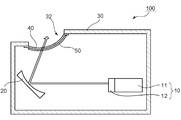
- FIG. 1 is a partial schematic cross-sectional view for explaining a head-up display device according to an embodiment of the present invention.
- the head-up display device 100 includes a display cell 11 and a first polarizing plate 12 with a retardation layer, and a display 10 for emitting projection light; and at least one reflector for reflecting the projection light (in the illustrated example, A housing 30 having one reflector 20) and an opening 32 and accommodating the display 10 and the reflector 20 therein; a cover member 40 covering the opening 32; a housing of the cover member 40 And a second polarizing plate with retardation layer 50 provided on the inner side.
- one reflector 20 is provided in the embodiment of FIG. 1, two reflectors 20, 22 may be provided as in the head-up display device 101 shown in FIG.
- any appropriate configuration may be employed as the display 10.
- a liquid crystal display device is mentioned as a representative example of a display. Therefore, as the display cell 11, a liquid crystal cell can be mentioned. Any appropriate configuration may be employed as a configuration of the liquid crystal cell (for example, a drive mode).
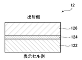
- the display 10 includes the display cell 11 and the first polarizing plate 12 with a retardation layer as described above.
- the first polarizing plate 12 with a retardation layer is typically bonded to the output side of the display cell 11 via an adhesive.
- the first retardation layer-provided polarizing plate 12 includes a polarizer 124 and a first retardation layer 126 in order from the display cell 11 side.
- the first retardation layer polarizing plate 12 may include a substrate 122 on the display cell 11 side of the polarizer 124 as necessary.
- the in-plane retardation Re (550) of the first retardation layer 126 is 100 nm to 200 nm.
- nx is the refractive index in the direction in which the in-plane refractive index is maximized (ie, the slow axis direction), and “ny” is the direction orthogonal to the in-plane slow axis (ie, the phase advance Axial refractive index).
- the reflector 20 has, for example, a mirror portion and a mirror holder for holding the mirror portion at a predetermined position of the housing 30.
- the mirror portion may be a plane mirror or a concave mirror.
- a concave mirror is employed.
- the projected image can be enlarged and displayed.
- the radius of curvature of the concave mirror can be appropriately set according to the purpose, the size of the image to be projected, and the like.
- the reflector 22 may be, for example, a flat mirror (cold mirror) that transmits only infrared light and reflects visible light and ultraviolet light.
- the housing 30 is a box-like member having an internal space capable of housing the display 10 and the reflectors 20 and 22.
- the housing 30 typically has an opening 32, and projection light emitted from the display 10 through the opening 32 is emitted to the outside of the housing 30.
- Housing 30 may be comprised of any suitable material.
- a material which is difficult to heat up by irradiation of sunlight and is easy to form can be mentioned. Specific examples of such materials include acrylic resins, epoxy resins, polyester resins, urethane resins, polyolefin resins, fluorine resins, and phenoxy resins.
- the housing 30 may be incorporated in part of a car or may be a member independent of the car. For example, a dashboard of a car may be used as the housing.
- the cover member 40 is a plate-like member that covers the opening 32 of the housing 30 so that dust does not enter the inside of the housing 30.
- the cover member 40 is typically transparent, and projection light reflected from the reflector 20 is transmitted through the cover member 40 and emitted to the outside of the housing 30. Details of the cover member will be described later in Section B.
- the second polarizing plate 50 with a retardation layer is bonded to the inside of the cover member 40 via the adhesive.
- the second polarizing plate with retardation layer 50 includes a polarizer 54 and a second retardation layer 56 in order from the cover member 40 side.
- the second retardation layer polarizing plate 50 may include a substrate 52 on the cover member 40 side of the polarizer 54 as necessary.
- the in-plane retardation Re (550) of the second retardation layer 56 is 100 nm to 200 nm.
- the angle between the slow axis of the second retardation layer and the absorption axis of the polarizer is a predetermined angle (described later: particularly preferably 45) By setting it in the vicinity of °), it has a function of converting linearly polarized light into circularly polarized light or elliptically polarized light, or a function of converting circularly polarized light or elliptically polarized light into linearly polarized light.
- projection light (circularly polarized light or elliptically polarized light) emitted from the display (liquid crystal display device) can be favorably converted into linearly polarized light and emitted to the outside of the housing 30.
- natural light from the outside is converted into circularly polarized light or elliptically polarized light by the second retardation layer, and when the circularly polarized light or elliptically polarized light is reflected inside the housing, the rotational direction is reversed.
- Such reflected (rotationally reversed) circularly polarized light or elliptically polarized light may be absorbed by the second retardation layer, and emission to the outside of the housing may be substantially prevented.
- the brightness of the projection light from the display released to the outside of the housing can be maintained high, and the visibility inside the housing is significantly reduced (that is, the concealability inside the housing is extremely reduced) Be excellent).
- the first polarizing plate with retardation layer (first retardation layer) and the second polarizing plate with retardation layer (second retardation layer) are respectively placed at predetermined positions in the head-up display device.
- first retardation layer first retardation layer
- second retardation layer the second retardation layer-attached polarizing plate.
- the details of the second retardation layer-attached polarizing plate will be described later in Section C together with the first retardation layer-attached polarizing plate.
- the absorption axes of the respective polarizers are substantially parallel to each other in the first retardation-layer-attached polarizing plate and the second retardation-layer-attached polarizing plate.
- the first retardation layer polarizing plate and the second retardation layer polarizing plate are typically arranged such that the slow axes of the respective retardation layers are substantially orthogonal to each other. .
- the expressions “substantially parallel” and “substantially parallel” include cases where an angle formed by two directions is 0 ° ⁇ 7 °, preferably 0 ° ⁇ 5 °. More preferably, it is 0 ° ⁇ 3 °.
- the expressions “substantially orthogonal” and “substantially orthogonal” include cases where the angle formed by the two directions is 90 ° ⁇ 7 °, preferably 90 ° ⁇ 5 °, more preferably 90 ° ⁇ . It is 3 degrees.
- orthogonal or “parallel”
- the mirror holder has, for example, an axis whose circumferential surface is connected to the back surface of the mirror, and a controller connected to the end of the axis. Since the angle of the mirror unit changes in accordance with the rotation of the shaft, the control unit can indirectly adjust the angle of the mirror unit by controlling the rotation of the shaft. The angle of the mirror may typically be adjusted according to the shape of the windshield.
- the head-up display device will not be described because any suitable configuration commonly used in the industry is adopted.
- the cover member and the polarizing plate with a retardation layer will be specifically described.
- the cover member 40 is typically transparent, as described above.
- “transparent” means having the property of transmitting visible light with a wavelength of 360 nm to 830 nm. Transparent substantially does not absorb visible light and transmits light of all wavelengths in the visible light range (colorless and transparent), and absorbs light of a part of wavelengths in the visible light range, and its wavelengths Other cases of transmitting light (colored and transparent) are included.
- the cover member 40 is preferably colorless and transparent.
- the total light transmittance of the cover member is preferably 50% or more, more preferably 70% or more, and still more preferably 90% or more. The total light transmittance is a value measured according to JIS K7375.
- the thickness of the cover member may be, for example, 10 ⁇ m to 1000 ⁇ m. If the cover member is too thick, the transmittance of the projection light may be reduced (the light loss of the projection light may be increased), which may contribute to the generation of a double image. If the cover member is too thin, the mechanical strength may be insufficient and the covering function may be insufficient.
- the cover member may be composed of any suitable transparent material. Typical examples include resin and glass. Specific examples of the resin include: ester-based resins such as polyethylene terephthalate and polyethylene naphthalate; cellulose-based resins such as diacetyl cellulose and triacetyl cellulose; polycarbonate-based resins such as bisphenol A-based polycarbonate; acrylic resins such as polymethyl methacrylate Acrylic resins such as lactone-modified acrylic resin; styrene resins such as polystyrene and acrylonitrile / styrene copolymer; polyethylene, polypropylene, olefin resins having cyclic structure or norbornene structure, and olefin resin such as ethylene / propylene copolymer Vinyl-based resins; amide-based resins such as aromatic polyamides; imide-based resins; sulfone-based resins; polyethersulfone-based resins; Rensurufido resin
- first Retardation Layer Polarizing Plate and Second Retardation Layer Polarizing Plate The constituent elements of the first retardation layer polarizing plate and the second retardation layer polarizing plate (typically, polarization).
- the same explanation applies to the elements 124 and 54, the first retardation layer 126 and the second retardation layer 56, and the substrates 122 and 52).
- the polarizers 124 and 54 may be identical to or different from each other. The same applies to the first retardation layer 56 and the second retardation layer 126, and to the substrates 122 and 52.
- Polarizer Any appropriate polarizer may be employed as the polarizer. Representative examples include iodine-based polarizers and lyotropic liquid crystal polarizers.
- the resin film forming the iodine-based polarizer may be a single-layer resin film, or may be produced using a laminate of two or more layers.
- the polarizer composed of a single-layer resin film examples include polyvinyl alcohol (PVA) based resin film, partially formalized PVA based resin film, ethylene / vinyl acetate copolymer based partially saponified film, etc.
- PVA polyvinyl alcohol
- a polarizer obtained by dyeing a PVA-based resin film with iodine and uniaxially stretching it is used because of excellent optical properties.
- staining by the said iodine is performed by immersing a PVA-type resin film in iodine aqueous solution, for example.
- the stretching ratio of the uniaxial stretching is preferably 3 to 7 times. Stretching may be carried out after the dyeing process or may be carried out while dyeing. Moreover, it may be dyed after being drawn.
- the PVA resin film is subjected to swelling treatment, crosslinking treatment, washing treatment, drying treatment, and the like. For example, by immersing and washing the PVA-based resin film in water prior to dyeing, it is possible not only to clean the stains and antiblocking agents on the surface of the PVA-based resin film, but also to swell the PVA-based resin film and dye it. Unevenness can be prevented.
- the polarizer obtained by using a laminate a laminate of a resin substrate and a PVA-based resin layer (PVA-based resin film) laminated on the resin substrate, or a resin substrate and the resin
- coated-formed to the base material is mentioned.
- coated and formed by the said resin base material applies a PVA-type resin solution to a resin base material, for example, it is made to dry, and a resin base material Forming a PVA-based resin layer thereon to obtain a laminate of the resin base and the PVA-based resin layer; stretching and dyeing the laminate to make the PVA-based resin layer as a polarizer; obtain.
- stretching typically includes dipping the laminate in a boric acid aqueous solution and stretching.
- stretching may optionally further comprise air-stretching the laminate at a high temperature (eg, 95 ° C. or higher) prior to stretching in an aqueous boric acid solution.
- the resulting laminate of resin substrate / polarizer may be used as it is (that is, the resin substrate may be used as a protective layer of polarizer), and the resin substrate is peeled off from the laminate of resin substrate / polarizer.
- any appropriate protective layer depending on the purpose may be laminated on the peeled surface.
- the details of the method for producing such a polarizer are described, for example, in JP-A-2012-73580. The publication is incorporated herein by reference in its entirety.
- the lyotropic liquid crystal polarizer is excellent in heat resistance, and as a result, the heat resistance of the head-up display device can be further improved.
- the lyotropic liquid crystal polarizer includes, for example, an aromatic disazo compound represented by the following formula (1):
- Q 1 represents a substituted or unsubstituted aryl group
- Q 2 represents a substituted or unsubstituted arylene group
- R 1 each independently represents a hydrogen atom, a substituted or unsubstituted group
- R represents an alkyl group, substituted or unsubstituted acetyl group, substituted or unsubstituted benzoyl group, substituted or unsubstituted phenyl group
- M represents a counter ion
- m is an integer of 0 to 2
- n is 0
- at least one of m and n is not 0, 1 ⁇ m + n ⁇ 6, and when m is 2, each R 1 may be the same or
- the naphthyl group and the azo group are bonded at the 1- or 2-position of the naphthyl group.
- R 1 is preferably a hydrogen atom, a substituted or unsubstituted alkyl group, or a substituted or unsubstituted acetyl group, more preferably a hydrogen atom.
- the substituted or unsubstituted alkyl group includes a substituted or unsubstituted alkyl group having 1 to 6 carbon atoms.
- M (counter ion) of the formula (1) is preferably a hydrogen ion; an alkali metal ion such as Li, Na, K or Cs; an alkaline earth metal ion such as Ca, Sr or Ba; other metal ions; And ammonium ions optionally substituted by a group or a hydroxyalkyl group; salts of organic amines and the like.
- metal ions include Ni + , Fe 3 + , Cu 2 + , Ag 2 + , Zn 2 + , Al 3 + , Pd 2 + , Cd 2 + , Sn 2 + , Co 2 + , Mn 2 + , Ce 3 + .
- the aryl group represented by Q 1 in the formula (1) includes, in addition to a phenyl group, a fused ring group in which two or more benzene rings such as a naphthyl group are condensed.
- the arylene group represented by Q 2 includes, in addition to a phenylene group, a fused ring group in which two or more benzene rings such as a naphthylene group are fused.
- the aryl group of Q 1 or the arylene group of Q 2 may or may not have a substituent.
- the aromatic disazo compound of the formula (1) having a polar group is excellent in solubility in an aqueous solvent, regardless of whether the aryl group or the arylene group is substituted or unsubstituted.
- the substituent is one selected from an alkoxy group having 1 to 6 carbon atoms, a hydroxyalkyl group having 1 to 6 carbon atoms, a carboxyl group, a sulfonic acid group, and a nitro group.
- the aromatic disazo compound which has such a substituent is especially excellent in water solubility.
- the aryl group or arylene group may be substituted by one of these substituents, or may be substituted by two or more. Also, the substituents may be substituted in any ratio.
- Q 1 in the formula (1) is preferably a substituted or unsubstituted phenyl group, more preferably a phenyl group having the above-mentioned substituent.
- Q 2 is preferably a substituted or unsubstituted naphthylene group, more preferably a naphthylene group having the above-described substituent, and particularly preferably a 1,4-naphthylene group having the above-described substituent.
- R 1 , M, m and n are as described for Formula (1) above.
- a and B represent a substituent, and a and b represent the substitution number.
- a and B are each independently an alkyl group having 1 to 6 carbon atoms, an alkoxy group having 1 to 6 carbon atoms, an alkylamino group having 1 to 6 carbon atoms, a phenylamino group, an acylamino group having 1 to 6 carbon atoms And a hydroxyalkyl group having 1 to 6 carbon atoms such as a dihydroxypropyl group, a carboxyl group such as a COOM group, a sulfonic acid group such as an SO 3 M group, a hydroxyl group, a cyano group, a nitro group, an amino group and a halogeno group.
- a is an integer of 0 to 5
- b is an integer of 0 to 4. However, at least one of a and b is not zero.
- the substituents A may be the same or different.
- the substituents B may be the same or different.
- aromatic disazo compounds represented by the following formula (3) are preferable.
- the OH group of the naphthyl group is bonded to the position (ortho position) adjacent to the azo group.
- R 1 , M, m and n are as described for Formula (1), and A is as described for Formula (2).
- p represents an integer of 0 to 4. p is preferably 1 or 2, more preferably 1.
- the aromatic disazo compounds represented by the above formulas (1) to (3) can be produced, for example, by Toyo Hosoda "Theoretical manufacture dye chemistry (5th edition)" (July 15, 1947, published by Jichihodo, pages 135 to 152). Can be synthesized according to For example, after the aromatic disazo compound of the formula (3) is subjected to diazotization and coupling reaction of an aniline derivative and a naphthalenesulfonic acid derivative to obtain a monoazo compound, this monoazo compound is diazotized and further 1-amino- It can be synthesized by coupling reaction with an 8-naphthol sulfonic acid derivative.
- the lyotropic liquid crystal polarizer can be produced, for example, by a method including the following step B and step C.
- the step A may be performed before the step B, and the step D may be performed after the step C.
- Step A a step of subjecting the surface of the substrate to an orientation treatment.
- Step B A step of applying a coating solution containing the aromatic disazo compound represented by the above formula (1) on the surface of a substrate to form a coating.
- Step C A step of drying the coated film to form a polarizer which is a dried coated film.
- Process D A process of subjecting the surface of the polarizer obtained in Process C to a water resistance treatment.
- the polarizing plate with a retardation layer which has an orientation film between a base material and a polarizer is produced.
- the substrate may be used as it is (in this case, the substrate may function as a protective layer of a polarizer), and the substrate may be peeled off to provide any appropriate protective film on the peeled surface.
- Process B is a process of forming a coating film using a coating liquid.
- the coating liquid contains the above-mentioned aromatic disazo compound and a solvent for dissolving or dispersing the aromatic disazo compound.
- the coating liquid is obtained by dissolving or dispersing the aromatic disazo compound in a solvent.
- any suitable solvent can be used as a solvent for dissolving or dispersing the aromatic disazo compound.
- Aqueous solvents are preferred.
- the aqueous solvent include water, a hydrophilic solvent, and a mixed solvent of water and a hydrophilic solvent.
- the hydrophilic solvent is a solvent which dissolves substantially uniformly in water.
- hydrophilic solvents include alcohols such as methanol and isopropyl alcohol; glycols such as ethylene glycol; cellosolves such as methyl cellosolve and ethyl cellosolve; ketones such as acetone and methyl ethyl ketone; esters such as ethyl acetate; It can be mentioned.
- the aqueous solvent preferably, water or a mixed solvent of water and a hydrophilic solvent is used.
- the aromatic disazo compound represented by the above formula (1) is an organic compound having lyotropic liquid crystallinity. Therefore, the coating liquid exhibits a lyotropic liquid crystal phase by changing the liquid temperature, the concentration of the aromatic disazo compound, and the like.
- the lyotropic liquid crystal phase is generated by the formation of a supramolecular association in the liquid by the aromatic disazo compound.
- the lyotropic liquid crystal phase can be identified and identified by the optical pattern observed with a polarizing microscope.
- the supramolecular association is one large complex formed by bonding a plurality of aromatic disazo compounds by hydrogen bond or the like.
- the (meth) acrylic resin has a Tg (glass transition temperature) of preferably 115 ° C. or more, more preferably 120 ° C. or more, still more preferably 125 ° C. or more, particularly preferably 130 ° C. or more. It is because it is excellent in durability.
- the upper limit of the Tg of the (meth) acrylic resin is not particularly limited, but is preferably 170 ° C. or less from the viewpoint of formability and the like.
- Retardation Layer-Containing Polarizing Plate The laminate of the base material / polarizer and the retardation film were pasted together so that the polarizer and the retardation film faced each other.
- an acrylic pressure-sensitive adhesive manufactured by Nitto Denko Corporation, product name “CS9861UA”
- bonding was performed such that the absorption axis of the polarizer and the slow axis of the retardation film form an angle of 45 °.
- a polarizing plate with a retardation layer having a constitution of base material / polarizer / retardation film (retardation layer) was obtained.
- Two polarizing plates with retardation layer were prepared, and it was set as the 1st polarizing plate with retardation layer and the 2nd polarizing plate with retardation layer.
- Example 2 A head-up display device compatible product was produced in the same manner as in Example 1 except that the retardation value of both the first retardation layer and the second retardation layer was 110 nm. The obtained product corresponding to the head-up display device was subjected to the same evaluation as in Example 1. The results are shown in Table 1.
- Example 4 A head-up display device compatible product was produced in the same manner as in Example 1 except that the retardation value of the first retardation layer was 120 nm, and the retardation value of the second retardation layer was 190 nm.
- the obtained product corresponding to the head-up display device was subjected to the same evaluation as in Example 1. The results are shown in Table 1.
- Comparative Example 1 A head-up display device compatible product was produced in the same manner as in Example 1 except that the first retardation layer was not provided. The obtained product corresponding to the head-up display device was subjected to the same evaluation as in Example 1. The results are shown in Table 1.
- Comparative Example 2 A head-up display device compatible product was produced in the same manner as in Example 1 except that neither the first retardation layer nor the second retardation layer was provided. The obtained product corresponding to the head-up display device was subjected to the same evaluation as in Example 1. The results are shown in Table 1.
- the head-up display device of the example satisfies the internal concealability and the display brightness at the same time.
Landscapes
- Engineering & Computer Science (AREA)
- Physics & Mathematics (AREA)
- Chemical & Material Sciences (AREA)
- Combustion & Propulsion (AREA)
- Transportation (AREA)
- Mechanical Engineering (AREA)
- General Physics & Mathematics (AREA)
- Optics & Photonics (AREA)
- Polarising Elements (AREA)
- Liquid Crystal (AREA)
Abstract
L'objet de la présente invention est de fournir un dispositif d'affichage tête haute apte à fournir simultanément une luminance d'affichage et une capacité d'occultation satisfaisantes pour l'intérieur. Un dispositif d'affichage tête haute (100) selon la présente invention comprend : un affichage (10) qui comprend une cellule d'affichage (11) et une plaque de polarisation (12) ayant une première couche de retard et qui émet une lumière de projection, ladite plaque de polarisation (12) étant sur le côté émission de la cellule d'affichage (11) et contenant séquentiellement un polariseur et une première couche de retard à partir du côté cellule d'affichage; au moins un réflecteur (20) qui réfléchit la lumière de projection; un boîtier (30) qui a une ouverture (32) et contient intérieurement l'affichage (10) et le réflecteur (20); un élément de couvercle (40) qui recouvre l'ouverture (32); et une plaque de polarisation (50) ayant une seconde couche de retard, qui est disposée sur le côté intérieur de boîtier de l'élément de couvercle (40) et contient séquentiellement un polariseur et une seconde couche de retard à partir du côté de l'élément de couvercle. Les retards dans le plan Re (550) de la première couche de retard et de la seconde couche de retard sont compris respectivement entre 100 nm et 200 nm.
Priority Applications (4)
| Application Number | Priority Date | Filing Date | Title |
|---|---|---|---|
| US16/756,957 US11567315B2 (en) | 2017-11-09 | 2018-10-16 | Head-up display device |
| EP18876797.4A EP3709070A4 (fr) | 2017-11-09 | 2018-10-16 | Dispositif d'affichage tête haute |
| KR1020207010426A KR102716173B1 (ko) | 2017-11-09 | 2018-10-16 | 헤드업 디스플레이 장치 |
| CN201880067760.0A CN111226159B (zh) | 2017-11-09 | 2018-10-16 | 抬头显示器装置 |
Applications Claiming Priority (4)
| Application Number | Priority Date | Filing Date | Title |
|---|---|---|---|
| JP2017216115 | 2017-11-09 | ||
| JP2017-216115 | 2017-11-09 | ||
| JP2018194391A JP2019086766A (ja) | 2017-11-09 | 2018-10-15 | ヘッドアップディスプレイ装置 |
| JP2018-194391 | 2018-10-15 |
Publications (1)
| Publication Number | Publication Date |
|---|---|
| WO2019093079A1 true WO2019093079A1 (fr) | 2019-05-16 |
Family
ID=66437847
Family Applications (1)
| Application Number | Title | Priority Date | Filing Date |
|---|---|---|---|
| PCT/JP2018/038450 Ceased WO2019093079A1 (fr) | 2017-11-09 | 2018-10-16 | Dispositif d'affichage tête haute |
Country Status (1)
| Country | Link |
|---|---|
| WO (1) | WO2019093079A1 (fr) |
Cited By (1)
| Publication number | Priority date | Publication date | Assignee | Title |
|---|---|---|---|---|
| JP2023013968A (ja) * | 2021-07-16 | 2023-01-26 | 中強光電股▲ふん▼有限公司 | ヘッドアップディスプレイ |
Citations (33)
| Publication number | Priority date | Publication date | Assignee | Title |
|---|---|---|---|---|
| JPS5083482A (fr) | 1973-11-26 | 1975-07-05 | ||
| JPS62225429A (ja) * | 1986-03-28 | 1987-10-03 | Yazaki Corp | 車載用ヘツドアツプデイスプレイ装置 |
| JPH01240517A (ja) | 1988-03-22 | 1989-09-26 | Japan Synthetic Rubber Co Ltd | 重合体並びにその前駆体および製造方法 |
| JPH02113920A (ja) | 1988-10-25 | 1990-04-26 | Mitsubishi Kasei Corp | 延伸フィルム又はシートの製造方法 |
| JPH0314882A (ja) | 1989-03-10 | 1991-01-23 | Mitsui Petrochem Ind Ltd | メッキ用組成物およびメッキ物 |
| JPH03122137A (ja) | 1989-10-06 | 1991-05-24 | Japan Synthetic Rubber Co Ltd | 熱可塑性樹脂成形品 |
| JPH03182701A (ja) | 1989-12-13 | 1991-08-08 | Nippon Kayaku Co Ltd | 延伸フィルム及びその製造法 |
| JPH06885U (ja) * | 1992-06-05 | 1994-01-11 | 日本精機株式会社 | 車両用表示装置 |
| JP2000009912A (ja) | 1998-06-25 | 2000-01-14 | Nitto Denko Corp | 延伸フィルムの製造方法及び位相差板 |
| JP2000230016A (ja) | 1998-12-09 | 2000-08-22 | Nippon Shokubai Co Ltd | 透明性耐熱樹脂の製造方法とその用途 |
| WO2001037007A1 (fr) | 1999-11-12 | 2001-05-25 | Kaneka Corporation | Film transparent |
| JP2001151814A (ja) | 1999-11-26 | 2001-06-05 | Nippon Shokubai Co Ltd | 透明性耐熱樹脂の製造方法およびその用途 |
| JP2001343529A (ja) | 2000-03-30 | 2001-12-14 | Kanegafuchi Chem Ind Co Ltd | 偏光子保護フィルムおよびその製造方法 |
| JP2002022944A (ja) | 2000-07-06 | 2002-01-23 | Fuji Photo Film Co Ltd | 円偏光板およびその製造方法 |
| JP2002086554A (ja) | 2000-07-10 | 2002-03-26 | Fuji Photo Film Co Ltd | ポリマーフィルムの延伸方法、偏光膜、偏光板および位相差膜の製造方法、および液晶表示装置 |
| JP2002120326A (ja) | 2000-10-18 | 2002-04-23 | Nippon Shokubai Co Ltd | 透明熱可塑性樹脂積層体 |
| JP2002254544A (ja) | 2001-03-05 | 2002-09-11 | Nippon Shokubai Co Ltd | 熱可塑性樹脂積層体 |
| JP2004070296A (ja) | 2002-06-14 | 2004-03-04 | Toray Ind Inc | 偏光板保護シートおよび偏光板 |
| JP2005146084A (ja) | 2003-11-13 | 2005-06-09 | Nippon Shokubai Co Ltd | ラクトン環含有重合体とその製造方法ならびに用途 |
| JP2007171943A (ja) | 2005-11-28 | 2007-07-05 | Nitto Denko Corp | 光学補償層付偏光板およびそれを用いた画像表示装置 |
| JP2008070504A (ja) | 2006-09-13 | 2008-03-27 | Nippon Seiki Co Ltd | 表示装置 |
| JP2010152005A (ja) * | 2008-12-24 | 2010-07-08 | Nippon Sheet Glass Co Ltd | ヘッドアップディスプレイ |
| JP2012073580A (ja) | 2010-09-03 | 2012-04-12 | Nitto Denko Corp | 薄型偏光膜の製造方法 |
| JP2012194357A (ja) * | 2011-03-16 | 2012-10-11 | Nitto Denko Corp | 偏光フィルム、コーティング液、及び画像表示装置 |
| US20130279016A1 (en) * | 2010-12-23 | 2013-10-24 | Eckhard Finger | Head-up display for a motor vehicle |
| JP2014010291A (ja) | 2012-06-29 | 2014-01-20 | Nitto Denko Corp | 円偏光板および表示装置 |
| JP2014026266A (ja) | 2012-06-21 | 2014-02-06 | Nitto Denko Corp | 偏光板および有機elパネル |
| JP2015005272A (ja) | 2013-05-22 | 2015-01-08 | 日東電工株式会社 | 両面透明導電性フィルムおよびタッチパネル |
| JP2015115171A (ja) | 2013-12-11 | 2015-06-22 | 日東電工株式会社 | 透明導電性フィルム及びその用途 |
| JP2015120870A (ja) | 2013-11-20 | 2015-07-02 | Dicグラフィックス株式会社 | 印刷インキ組成物 |
| JP2015141674A (ja) | 2014-01-30 | 2015-08-03 | 日東電工株式会社 | 両面透明導電性フィルム及びその巻回体、並びにタッチパネル |
| JP2015222337A (ja) * | 2014-05-23 | 2015-12-10 | 日本精機株式会社 | 表示装置 |
| WO2017094248A1 (fr) * | 2015-12-01 | 2017-06-08 | パナソニックIpマネジメント株式会社 | Lentille à surface de forme libre et affichage tête haute |
-
2018
- 2018-10-16 WO PCT/JP2018/038450 patent/WO2019093079A1/fr not_active Ceased
Patent Citations (33)
| Publication number | Priority date | Publication date | Assignee | Title |
|---|---|---|---|---|
| JPS5083482A (fr) | 1973-11-26 | 1975-07-05 | ||
| JPS62225429A (ja) * | 1986-03-28 | 1987-10-03 | Yazaki Corp | 車載用ヘツドアツプデイスプレイ装置 |
| JPH01240517A (ja) | 1988-03-22 | 1989-09-26 | Japan Synthetic Rubber Co Ltd | 重合体並びにその前駆体および製造方法 |
| JPH02113920A (ja) | 1988-10-25 | 1990-04-26 | Mitsubishi Kasei Corp | 延伸フィルム又はシートの製造方法 |
| JPH0314882A (ja) | 1989-03-10 | 1991-01-23 | Mitsui Petrochem Ind Ltd | メッキ用組成物およびメッキ物 |
| JPH03122137A (ja) | 1989-10-06 | 1991-05-24 | Japan Synthetic Rubber Co Ltd | 熱可塑性樹脂成形品 |
| JPH03182701A (ja) | 1989-12-13 | 1991-08-08 | Nippon Kayaku Co Ltd | 延伸フィルム及びその製造法 |
| JPH06885U (ja) * | 1992-06-05 | 1994-01-11 | 日本精機株式会社 | 車両用表示装置 |
| JP2000009912A (ja) | 1998-06-25 | 2000-01-14 | Nitto Denko Corp | 延伸フィルムの製造方法及び位相差板 |
| JP2000230016A (ja) | 1998-12-09 | 2000-08-22 | Nippon Shokubai Co Ltd | 透明性耐熱樹脂の製造方法とその用途 |
| WO2001037007A1 (fr) | 1999-11-12 | 2001-05-25 | Kaneka Corporation | Film transparent |
| JP2001151814A (ja) | 1999-11-26 | 2001-06-05 | Nippon Shokubai Co Ltd | 透明性耐熱樹脂の製造方法およびその用途 |
| JP2001343529A (ja) | 2000-03-30 | 2001-12-14 | Kanegafuchi Chem Ind Co Ltd | 偏光子保護フィルムおよびその製造方法 |
| JP2002022944A (ja) | 2000-07-06 | 2002-01-23 | Fuji Photo Film Co Ltd | 円偏光板およびその製造方法 |
| JP2002086554A (ja) | 2000-07-10 | 2002-03-26 | Fuji Photo Film Co Ltd | ポリマーフィルムの延伸方法、偏光膜、偏光板および位相差膜の製造方法、および液晶表示装置 |
| JP2002120326A (ja) | 2000-10-18 | 2002-04-23 | Nippon Shokubai Co Ltd | 透明熱可塑性樹脂積層体 |
| JP2002254544A (ja) | 2001-03-05 | 2002-09-11 | Nippon Shokubai Co Ltd | 熱可塑性樹脂積層体 |
| JP2004070296A (ja) | 2002-06-14 | 2004-03-04 | Toray Ind Inc | 偏光板保護シートおよび偏光板 |
| JP2005146084A (ja) | 2003-11-13 | 2005-06-09 | Nippon Shokubai Co Ltd | ラクトン環含有重合体とその製造方法ならびに用途 |
| JP2007171943A (ja) | 2005-11-28 | 2007-07-05 | Nitto Denko Corp | 光学補償層付偏光板およびそれを用いた画像表示装置 |
| JP2008070504A (ja) | 2006-09-13 | 2008-03-27 | Nippon Seiki Co Ltd | 表示装置 |
| JP2010152005A (ja) * | 2008-12-24 | 2010-07-08 | Nippon Sheet Glass Co Ltd | ヘッドアップディスプレイ |
| JP2012073580A (ja) | 2010-09-03 | 2012-04-12 | Nitto Denko Corp | 薄型偏光膜の製造方法 |
| US20130279016A1 (en) * | 2010-12-23 | 2013-10-24 | Eckhard Finger | Head-up display for a motor vehicle |
| JP2012194357A (ja) * | 2011-03-16 | 2012-10-11 | Nitto Denko Corp | 偏光フィルム、コーティング液、及び画像表示装置 |
| JP2014026266A (ja) | 2012-06-21 | 2014-02-06 | Nitto Denko Corp | 偏光板および有機elパネル |
| JP2014010291A (ja) | 2012-06-29 | 2014-01-20 | Nitto Denko Corp | 円偏光板および表示装置 |
| JP2015005272A (ja) | 2013-05-22 | 2015-01-08 | 日東電工株式会社 | 両面透明導電性フィルムおよびタッチパネル |
| JP2015120870A (ja) | 2013-11-20 | 2015-07-02 | Dicグラフィックス株式会社 | 印刷インキ組成物 |
| JP2015115171A (ja) | 2013-12-11 | 2015-06-22 | 日東電工株式会社 | 透明導電性フィルム及びその用途 |
| JP2015141674A (ja) | 2014-01-30 | 2015-08-03 | 日東電工株式会社 | 両面透明導電性フィルム及びその巻回体、並びにタッチパネル |
| JP2015222337A (ja) * | 2014-05-23 | 2015-12-10 | 日本精機株式会社 | 表示装置 |
| WO2017094248A1 (fr) * | 2015-12-01 | 2017-06-08 | パナソニックIpマネジメント株式会社 | Lentille à surface de forme libre et affichage tête haute |
Non-Patent Citations (1)
| Title |
|---|
| YUTAKA HOSODA: "Theoretical Production Dye Chemistry Fifth Edition", 15 July 1968, GIHODO, pages: 135 - 152 |
Cited By (1)
| Publication number | Priority date | Publication date | Assignee | Title |
|---|---|---|---|---|
| JP2023013968A (ja) * | 2021-07-16 | 2023-01-26 | 中強光電股▲ふん▼有限公司 | ヘッドアップディスプレイ |
Similar Documents
| Publication | Publication Date | Title |
|---|---|---|
| JP7309264B2 (ja) | ヘッドアップディスプレイ装置 | |
| WO2020152949A1 (fr) | Dispositif d'affichage tête haute et son procédé de fabrication | |
| US11933979B2 (en) | Head-up display device | |
| KR102897693B1 (ko) | 헤드업 디스플레이 장치 및 그 제조 방법 | |
| CN111226159B (zh) | 抬头显示器装置 | |
| US11650419B2 (en) | Head-up display apparatus | |
| WO2019093079A1 (fr) | Dispositif d'affichage tête haute | |
| JP7253893B2 (ja) | ヘッドアップディスプレイ装置 | |
| WO2019078191A1 (fr) | Dispositif d'affichage tête haute | |
| WO2019078190A1 (fr) | Appareil d'affichage tête haute | |
| WO2019078192A1 (fr) | Appareil d'affichage tête haute |
Legal Events
| Date | Code | Title | Description |
|---|---|---|---|
| 121 | Ep: the epo has been informed by wipo that ep was designated in this application |
Ref document number: 18876797 Country of ref document: EP Kind code of ref document: A1 |
|
| NENP | Non-entry into the national phase |
Ref country code: DE |
|
| ENP | Entry into the national phase |
Ref document number: 2018876797 Country of ref document: EP Effective date: 20200609 |