WO2019093329A1 - 流体装置 - Google Patents
流体装置 Download PDFInfo
- Publication number
- WO2019093329A1 WO2019093329A1 PCT/JP2018/041191 JP2018041191W WO2019093329A1 WO 2019093329 A1 WO2019093329 A1 WO 2019093329A1 JP 2018041191 W JP2018041191 W JP 2018041191W WO 2019093329 A1 WO2019093329 A1 WO 2019093329A1
- Authority
- WO
- WIPO (PCT)
- Prior art keywords
- liquid
- valve
- electrode
- flow path
- value
- Prior art date
- Legal status (The legal status is an assumption and is not a legal conclusion. Google has not performed a legal analysis and makes no representation as to the accuracy of the status listed.)
- Ceased
Links
Images




Classifications
-
- F—MECHANICAL ENGINEERING; LIGHTING; HEATING; WEAPONS; BLASTING
- F16—ENGINEERING ELEMENTS AND UNITS; GENERAL MEASURES FOR PRODUCING AND MAINTAINING EFFECTIVE FUNCTIONING OF MACHINES OR INSTALLATIONS; THERMAL INSULATION IN GENERAL
- F16K—VALVES; TAPS; COCKS; ACTUATING-FLOATS; DEVICES FOR VENTING OR AERATING
- F16K31/00—Actuating devices; Operating means; Releasing devices
- F16K31/02—Actuating devices; Operating means; Releasing devices electric; magnetic
- F16K31/06—Actuating devices; Operating means; Releasing devices electric; magnetic using a magnet, e.g. diaphragm valves, cutting off by means of a liquid
- F16K31/0675—Electromagnet aspects, e.g. electric supply therefor
-
- F—MECHANICAL ENGINEERING; LIGHTING; HEATING; WEAPONS; BLASTING
- F16—ENGINEERING ELEMENTS AND UNITS; GENERAL MEASURES FOR PRODUCING AND MAINTAINING EFFECTIVE FUNCTIONING OF MACHINES OR INSTALLATIONS; THERMAL INSULATION IN GENERAL
- F16K—VALVES; TAPS; COCKS; ACTUATING-FLOATS; DEVICES FOR VENTING OR AERATING
- F16K31/00—Actuating devices; Operating means; Releasing devices
- F16K31/02—Actuating devices; Operating means; Releasing devices electric; magnetic
- F16K31/06—Actuating devices; Operating means; Releasing devices electric; magnetic using a magnet, e.g. diaphragm valves, cutting off by means of a liquid
- F16K31/0644—One-way valve
- F16K31/0655—Lift valves
-
- F—MECHANICAL ENGINEERING; LIGHTING; HEATING; WEAPONS; BLASTING
- F16—ENGINEERING ELEMENTS AND UNITS; GENERAL MEASURES FOR PRODUCING AND MAINTAINING EFFECTIVE FUNCTIONING OF MACHINES OR INSTALLATIONS; THERMAL INSULATION IN GENERAL
- F16K—VALVES; TAPS; COCKS; ACTUATING-FLOATS; DEVICES FOR VENTING OR AERATING
- F16K31/00—Actuating devices; Operating means; Releasing devices
- F16K31/02—Actuating devices; Operating means; Releasing devices electric; magnetic
- F16K31/06—Actuating devices; Operating means; Releasing devices electric; magnetic using a magnet, e.g. diaphragm valves, cutting off by means of a liquid
- F16K31/0603—Multiple-way valves
- F16K31/061—Sliding valves
- F16K31/0613—Sliding valves with cylindrical slides
-
- F—MECHANICAL ENGINEERING; LIGHTING; HEATING; WEAPONS; BLASTING
- F16—ENGINEERING ELEMENTS AND UNITS; GENERAL MEASURES FOR PRODUCING AND MAINTAINING EFFECTIVE FUNCTIONING OF MACHINES OR INSTALLATIONS; THERMAL INSULATION IN GENERAL
- F16K—VALVES; TAPS; COCKS; ACTUATING-FLOATS; DEVICES FOR VENTING OR AERATING
- F16K37/00—Special means in or on valves or other cut-off apparatus for indicating or recording operation thereof, or for enabling an alarm to be given
- F16K37/0025—Electrical or magnetic means
- F16K37/005—Electrical or magnetic means for measuring fluid parameters
-
- F—MECHANICAL ENGINEERING; LIGHTING; HEATING; WEAPONS; BLASTING
- F16—ENGINEERING ELEMENTS AND UNITS; GENERAL MEASURES FOR PRODUCING AND MAINTAINING EFFECTIVE FUNCTIONING OF MACHINES OR INSTALLATIONS; THERMAL INSULATION IN GENERAL
- F16K—VALVES; TAPS; COCKS; ACTUATING-FLOATS; DEVICES FOR VENTING OR AERATING
- F16K37/00—Special means in or on valves or other cut-off apparatus for indicating or recording operation thereof, or for enabling an alarm to be given
- F16K37/0075—For recording or indicating the functioning of a valve in combination with test equipment
- F16K37/0091—For recording or indicating the functioning of a valve in combination with test equipment by measuring fluid parameters
-
- G—PHYSICS
- G01—MEASURING; TESTING
- G01F—MEASURING VOLUME, VOLUME FLOW, MASS FLOW OR LIQUID LEVEL; METERING BY VOLUME
- G01F1/00—Measuring the volume flow or mass flow of fluid or fluent solid material wherein the fluid passes through a meter in a continuous flow
- G01F1/56—Measuring the volume flow or mass flow of fluid or fluent solid material wherein the fluid passes through a meter in a continuous flow by using electric or magnetic effects
-
- G—PHYSICS
- G01—MEASURING; TESTING
- G01F—MEASURING VOLUME, VOLUME FLOW, MASS FLOW OR LIQUID LEVEL; METERING BY VOLUME
- G01F1/00—Measuring the volume flow or mass flow of fluid or fluent solid material wherein the fluid passes through a meter in a continuous flow
- G01F1/56—Measuring the volume flow or mass flow of fluid or fluent solid material wherein the fluid passes through a meter in a continuous flow by using electric or magnetic effects
- G01F1/58—Measuring the volume flow or mass flow of fluid or fluent solid material wherein the fluid passes through a meter in a continuous flow by using electric or magnetic effects by electromagnetic flowmeters
- G01F1/584—Measuring the volume flow or mass flow of fluid or fluent solid material wherein the fluid passes through a meter in a continuous flow by using electric or magnetic effects by electromagnetic flowmeters constructions of electrodes, accessories therefor
-
- G—PHYSICS
- G01—MEASURING; TESTING
- G01F—MEASURING VOLUME, VOLUME FLOW, MASS FLOW OR LIQUID LEVEL; METERING BY VOLUME
- G01F1/00—Measuring the volume flow or mass flow of fluid or fluent solid material wherein the fluid passes through a meter in a continuous flow
- G01F1/56—Measuring the volume flow or mass flow of fluid or fluent solid material wherein the fluid passes through a meter in a continuous flow by using electric or magnetic effects
- G01F1/58—Measuring the volume flow or mass flow of fluid or fluent solid material wherein the fluid passes through a meter in a continuous flow by using electric or magnetic effects by electromagnetic flowmeters
- G01F1/588—Measuring the volume flow or mass flow of fluid or fluent solid material wherein the fluid passes through a meter in a continuous flow by using electric or magnetic effects by electromagnetic flowmeters combined constructions of electrodes, coils or magnetic circuits, accessories therefor
-
- G—PHYSICS
- G01—MEASURING; TESTING
- G01F—MEASURING VOLUME, VOLUME FLOW, MASS FLOW OR LIQUID LEVEL; METERING BY VOLUME
- G01F1/00—Measuring the volume flow or mass flow of fluid or fluent solid material wherein the fluid passes through a meter in a continuous flow
- G01F1/56—Measuring the volume flow or mass flow of fluid or fluent solid material wherein the fluid passes through a meter in a continuous flow by using electric or magnetic effects
- G01F1/58—Measuring the volume flow or mass flow of fluid or fluent solid material wherein the fluid passes through a meter in a continuous flow by using electric or magnetic effects by electromagnetic flowmeters
- G01F1/60—Circuits therefor
-
- G—PHYSICS
- G01—MEASURING; TESTING
- G01F—MEASURING VOLUME, VOLUME FLOW, MASS FLOW OR LIQUID LEVEL; METERING BY VOLUME
- G01F1/00—Measuring the volume flow or mass flow of fluid or fluent solid material wherein the fluid passes through a meter in a continuous flow
- G01F1/56—Measuring the volume flow or mass flow of fluid or fluent solid material wherein the fluid passes through a meter in a continuous flow by using electric or magnetic effects
- G01F1/64—Measuring the volume flow or mass flow of fluid or fluent solid material wherein the fluid passes through a meter in a continuous flow by using electric or magnetic effects by measuring electrical currents passing through the fluid flow; measuring electrical potential generated by the fluid flow, e.g. by electrochemical, contact or friction effects
-
- G—PHYSICS
- G01—MEASURING; TESTING
- G01F—MEASURING VOLUME, VOLUME FLOW, MASS FLOW OR LIQUID LEVEL; METERING BY VOLUME
- G01F15/00—Details of, or accessories for, apparatus of groups G01F1/00 - G01F13/00 insofar as such details or appliances are not adapted to particular types of such apparatus
- G01F15/005—Valves
-
- B—PERFORMING OPERATIONS; TRANSPORTING
- B60—VEHICLES IN GENERAL
- B60T—VEHICLE BRAKE CONTROL SYSTEMS OR PARTS THEREOF; BRAKE CONTROL SYSTEMS OR PARTS THEREOF, IN GENERAL; ARRANGEMENT OF BRAKING ELEMENTS ON VEHICLES IN GENERAL; PORTABLE DEVICES FOR PREVENTING UNWANTED MOVEMENT OF VEHICLES; VEHICLE MODIFICATIONS TO FACILITATE COOLING OF BRAKES
- B60T8/00—Arrangements for adjusting wheel-braking force to meet varying vehicular or ground-surface conditions, e.g. limiting or varying distribution of braking force
- B60T8/32—Arrangements for adjusting wheel-braking force to meet varying vehicular or ground-surface conditions, e.g. limiting or varying distribution of braking force responsive to a speed condition, e.g. acceleration or deceleration
- B60T8/34—Arrangements for adjusting wheel-braking force to meet varying vehicular or ground-surface conditions, e.g. limiting or varying distribution of braking force responsive to a speed condition, e.g. acceleration or deceleration having a fluid pressure regulator responsive to a speed condition
- B60T8/36—Arrangements for adjusting wheel-braking force to meet varying vehicular or ground-surface conditions, e.g. limiting or varying distribution of braking force responsive to a speed condition, e.g. acceleration or deceleration having a fluid pressure regulator responsive to a speed condition including a pilot valve responding to an electromagnetic force
- B60T8/3615—Electromagnetic valves specially adapted for anti-lock brake and traction control systems
- B60T8/363—Electromagnetic valves specially adapted for anti-lock brake and traction control systems in hydraulic systems
-
- F—MECHANICAL ENGINEERING; LIGHTING; HEATING; WEAPONS; BLASTING
- F16—ENGINEERING ELEMENTS AND UNITS; GENERAL MEASURES FOR PRODUCING AND MAINTAINING EFFECTIVE FUNCTIONING OF MACHINES OR INSTALLATIONS; THERMAL INSULATION IN GENERAL
- F16K—VALVES; TAPS; COCKS; ACTUATING-FLOATS; DEVICES FOR VENTING OR AERATING
- F16K11/00—Multiple-way valves, e.g. mixing valves; Pipe fittings incorporating such valves
- F16K11/02—Multiple-way valves, e.g. mixing valves; Pipe fittings incorporating such valves with all movable sealing faces moving as one unit
- F16K11/04—Multiple-way valves, e.g. mixing valves; Pipe fittings incorporating such valves with all movable sealing faces moving as one unit comprising only lift valves
- F16K11/044—Multiple-way valves, e.g. mixing valves; Pipe fittings incorporating such valves with all movable sealing faces moving as one unit comprising only lift valves with movable valve members positioned between valve seats
-
- F—MECHANICAL ENGINEERING; LIGHTING; HEATING; WEAPONS; BLASTING
- F16—ENGINEERING ELEMENTS AND UNITS; GENERAL MEASURES FOR PRODUCING AND MAINTAINING EFFECTIVE FUNCTIONING OF MACHINES OR INSTALLATIONS; THERMAL INSULATION IN GENERAL
- F16K—VALVES; TAPS; COCKS; ACTUATING-FLOATS; DEVICES FOR VENTING OR AERATING
- F16K27/00—Construction of housing; Use of materials therefor
- F16K27/02—Construction of housing; Use of materials therefor of lift valves
- F16K27/029—Electromagnetically actuated valves
-
- F—MECHANICAL ENGINEERING; LIGHTING; HEATING; WEAPONS; BLASTING
- F16—ENGINEERING ELEMENTS AND UNITS; GENERAL MEASURES FOR PRODUCING AND MAINTAINING EFFECTIVE FUNCTIONING OF MACHINES OR INSTALLATIONS; THERMAL INSULATION IN GENERAL
- F16K—VALVES; TAPS; COCKS; ACTUATING-FLOATS; DEVICES FOR VENTING OR AERATING
- F16K37/00—Special means in or on valves or other cut-off apparatus for indicating or recording operation thereof, or for enabling an alarm to be given
- F16K37/0025—Electrical or magnetic means
- F16K37/0041—Electrical or magnetic means for measuring valve parameters
-
- Y—GENERAL TAGGING OF NEW TECHNOLOGICAL DEVELOPMENTS; GENERAL TAGGING OF CROSS-SECTIONAL TECHNOLOGIES SPANNING OVER SEVERAL SECTIONS OF THE IPC; TECHNICAL SUBJECTS COVERED BY FORMER USPC CROSS-REFERENCE ART COLLECTIONS [XRACs] AND DIGESTS
- Y10—TECHNICAL SUBJECTS COVERED BY FORMER USPC
- Y10T—TECHNICAL SUBJECTS COVERED BY FORMER US CLASSIFICATION
- Y10T137/00—Fluid handling
- Y10T137/2496—Self-proportioning or correlating systems
- Y10T137/2514—Self-proportioning flow systems
- Y10T137/2521—Flow comparison or differential response
- Y10T137/2529—With electrical controller
-
- Y—GENERAL TAGGING OF NEW TECHNOLOGICAL DEVELOPMENTS; GENERAL TAGGING OF CROSS-SECTIONAL TECHNOLOGIES SPANNING OVER SEVERAL SECTIONS OF THE IPC; TECHNICAL SUBJECTS COVERED BY FORMER USPC CROSS-REFERENCE ART COLLECTIONS [XRACs] AND DIGESTS
- Y10—TECHNICAL SUBJECTS COVERED BY FORMER USPC
- Y10T—TECHNICAL SUBJECTS COVERED BY FORMER US CLASSIFICATION
- Y10T137/00—Fluid handling
- Y10T137/7722—Line condition change responsive valves
- Y10T137/7758—Pilot or servo controlled
- Y10T137/7761—Electrically actuated valve
Definitions
- the present invention relates to a fluid device including a flow path through which liquid flows.
- various fluid devices having a fluid flow path are known.
- fluidic devices include switching valves such as valves, three-way valves, and four-way valves, pumps for pumping fluid into the flow paths and pumps for suctioning the fluid, and manifolds provided with a plurality of flow paths.
- switching valves such as valves, three-way valves, and four-way valves
- pumps for pumping fluid into the flow paths and pumps for suctioning the fluid
- manifolds provided with a plurality of flow paths.
- a precise valve is employed as a fluid apparatus (see, for example, Patent Document 1).
- valve there is a valve provided with a valve body driven to move back and forth by an electromagnetic force, and a valve seat against which the valve body is pressed.
- the valve body is pressed against the valve seat to close the flow path, but when the valve body recedes from the valve seat, a gap is generated between the two and the flow path is opened.
- the present invention has been made in view of the above-mentioned conventional problems, and an object of the present invention is to provide a fluid apparatus having a function of detecting whether or not a liquid flowing state is appropriate.
- the present invention is a fluidic device comprising a flow path through which liquid flows, As an electrode for measuring the degree of electrical continuity of the liquid in the upstream flow path flowing in and the liquid in the downstream flow path flowing out, the first liquid electrically contacting the upstream liquid And a second electrode which is in electrical contact with the downstream fluid.
- the fluid device of the present invention includes a first electrode electrically connected to the upstream liquid and a second electrode electrically connected to the downstream liquid.
- the combination of the first electrode and the second electrode can be used to measure the degree of electrical conduction between the upstream fluid and the downstream fluid.
- the degree of electrical conduction between the upstream side liquid and the downstream side liquid can be measured relatively easily by using the first and second electrodes.
- the degree of electrical continuity corresponds to the presence or absence of the liquid flowing through the flow channel of the fluid device and the flow rate. Therefore, if the degree of electrical conduction is measured, it is possible to detect liquid leakage, liquid flow rate, and the like.
- the fluid device of the present invention is suitable for measuring the degree of electrical continuity between the upstream side liquid and the downstream side liquid, and it is easy to detect liquid leakage, clogging, and the like.
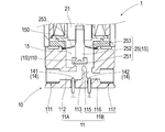
- FIG. 2 is a cross-sectional view showing a cross-sectional structure of a solenoid valve in Example 1;
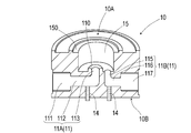
- FIG. 2 is a perspective view showing the cross-sectional structure of the flow passage portion in the first embodiment.
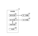
- FIG. 2 is a block diagram of a control unit incorporated in the solenoid valve according to the first embodiment.
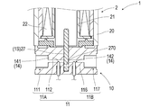
- FIG. 7 is an explanatory view showing an open valve state in the first embodiment.
- FIG. 7 is a perspective view showing the cross-sectional structure of another flow passage in the first embodiment.
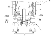
- Sectional drawing which shows the cross-section of a solenoid valve provided with a slider in Example 1 (closed state).
- Sectional drawing (open state) which shows the cross-section of a solenoid valve provided with a slider in Example 1.
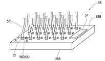
- FIG. 7 is a perspective view showing a manifold in Example 2;
- FIG. 16 is a perspective view of a manifold viewed from the tube connection surface side in the second embodiment.
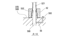
- FIG. 7 is a cross-sectional view showing an electrode of a manifold in Example 2;
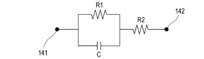
- FIG. 14 is a circuit diagram showing an equivalent circuit of an electrical path between electrodes in Example 3.
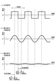
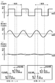
- the graph which shows an alternating current signal, an intermediate signal, and a detection signal in Example 3.
- FIG. FIG. 16 is a block diagram of a control unit in a fourth embodiment. The graph which shows an alternating current signal, an intermediate signal, and a detection signal in Example 4.
- FIG. 7 is a perspective view showing a manifold in Example 2
- FIG. 16 is a perspective view of a manifold viewed from the tube connection surface side in the second embodiment.
- FIG. 7 is a cross-sectional view showing an electrode of a manifold in Example 2;
- FIG. 14 is a circuit diagram showing an equivalent circuit
- the fluid device of the present invention is provided with a switching valve such as a valve, a three-way valve or a four-way valve, a pump for pumping the fluid into the flow passage or a pump for suctioning the fluid, and a pipe or tube having a flow passage There is a manifold etc.
- a pipe or tube having a flow path a straight single pipe may be used, or a branch pipe or a collecting pipe having a branch portion or a merging portion of the flow path may be used.
- the subject of the present invention is a variety of fluidic devices having fluid flow paths.
- a fluid apparatus includes a circuit that measures the degree of electrical conduction between the first electrode and the second electrode to detect the presence or absence of liquid flowing in the flow path. ing.
- the fluid device is a valve or the like that shuts off the flow of liquid, it is possible to detect a liquid leak when there is liquid flowing through the flow path in the state where the flow is shut off.
- a fluid device includes a circuit that measures the degree of electrical conduction between the first electrode and the second electrode to detect the amount of liquid flowing in the flow path.
- the flow path is a path through which liquid flows, and also serves as a path of electricity using liquid as a medium. Therefore, the degree of electrical conduction varies depending on, for example, the area of the flow path. If the area (especially the minimum area) of the flow path is increased, the flow rate is increased and the degree of electrical conduction is increased. By measuring the degree of electrical conduction, the amount of liquid flowing through the flow path can be detected.
- the fluid apparatus can set a state in which the flow of the liquid is blocked, and in the state in which the flow of the liquid is blocked, the upstream liquid and the downstream liquid are It has a structure that is electrically isolated.
- the first electrode and the second electrode are electrically insulated in a state in which the flow of the liquid is interrupted. For example, when the first electrode and the second electrode are electrically conducted in the shutoff state, it can be determined that the flow of the liquid is occurring, and the determination of the liquid leakage is facilitated.
- the flow rate can be adjusted by alternately switching the shutoff state and the open state in a fast cycle.
- the flow path is opened and the flow of the liquid is shut off so that the electric conduction degree is small. And periodically occur repeatedly.
- the occupation ratio of the period in which the flow path is opened and the degree of electrical conduction becomes large becomes large, the average value of the degree of electrical conduction becomes large, and the flow The amount (flow rate) of liquid flowing through the passage increases. Therefore, if the degree of electrical conduction is measured, the amount of liquid flowing through the flow path can be detected.
- the fluid device is a valve provided with a seal portion for blocking the flow of liquid in the middle of the flow path
- the first and second electrodes are electrodes for measuring the degree of electrical conduction between the upstream side liquid and the downstream side liquid adjacent to each other across the seal portion in the flow path. In this case, it is possible to measure the degree of electrical conduction between the upstream liquid and the downstream liquid adjacent to each other with the seal portion interposed therebetween.
- the valves include valves of various analyzers and inspection devices handling chemical solutions and sample liquids, valves of hydraulic machines operating with hydraulic pressure etc. as driving sources, valves of industrial machines such as refrigeration systems using fluid as medium, and so on. And valves for products for general consumers such as faucets such as kitchens and washbasins.
- the seal portion in the valve includes a valve seat and a valve body, and the valve body is pressed against the valve seat to close the valve to shut off the flow of the fluid and when a gap is generated between the valve seat and the valve body It may be open.
- this seal portion crystals may be deposited at the contact point between the valve seat and the valve body, and the crystal may fall into a state where the contact point between the valve seat and the valve body is trapped.
- the valve body includes a movable member that is displaced by the action of an electromagnetic force generated in response to energization, and a drive unit that drives the valve body by the displacement of the movable member, a hole that forms the flow path, and the valve seat It may be a valve having a formed flow path portion made of a non-conductive material.
- the drive unit may be a solenoid using a coil wound with an electric wire, or may be a solenoid using a laminated steel plate.
- the displacement of the movable member may be linear displacement, rotational displacement, rotational displacement or the like.
- a driving unit that includes a cylindrical coil wound with an electric wire and a columnar plunger inserted in the coil, the valve unit being driven by axial movement of the plunger, and the flow path It may be a valve having a flow passage portion made of a nonconductive material in which a hole is bored and the valve seat is formed.
- the upstream side liquid and the downstream side liquid are electrically insulated in a closed state, or both are electrically shorted. It is easy to realize such a structure. For example, even when the liquid on either one of the liquid on the upstream side and the liquid on the downstream side is in electrical contact with the conductive member that constitutes the drive unit, If electrical insulation with the liquid on the other side is ensured by the flow path, an electrical short circuit between the liquid on the upstream side and the liquid on the downstream side via the conductive member can be avoided.
- Example 1 a small solenoid valve 1 (valve) having a leak detection function is illustrated as an example of the fluid device.
- the contents will be described with reference to FIGS. 1 to 8.
- the solenoid valve 1 which is an example of a fluid apparatus is a valve in which the seal part 1S which includes the valve seat 110 and the valve body 25 is provided in the middle of the flow path 11 through which the liquid flows.
- the solenoid valve 1 is configured such that the valve body 25 presses against the valve seat 110 to close the valve, and a gap is generated between the valve seat 110 and the valve body 25 to open the valve.
- the solenoid valve 1 measures the degree of electrical conduction between the liquid on the upstream side and the liquid on the downstream side of the flow path 11, here, the liquid on the upstream side of the valve seat 110 and the valve body 25 in the flow path 11 and the liquid on the downstream side.
- the first electrode 141 electrically connected to the upstream liquid and the second electrode 142 electrically connected to the downstream liquid are provided as the electrodes 14 for measuring the The contents will be described in detail below.
- the solenoid valve 1 illustrated in FIG. 1 includes a drive unit 2 including a plunger 21 for driving a valve body 25, a flow passage unit 10 in which a flow passage 11 is formed, and a control unit 3 (see FIG. 3). And to be described later).
- a structure attached to the outer peripheral surface of the drive unit 2 a structure provided with a space inside the drive unit 2 (case 20), etc. Can be adopted.
- the drive unit 2 is configured by inserting and arranging a cylindrical plunger 21 inside a cylindrical coil 22 around which a wire is wound.
- the coil 22 is fixed to the inside of a bottomed cylindrical metal case 20.
- the winding ends at both ends of the coil 22 are taken out of the case 20 so that they can be connected to the control unit 3 fixed to the outside of the case 20, for example.
- the plunger 21 is a cylindrical component made of a ferromagnetic material.
- the plunger 21 is incorporated coaxially with a cylindrical spring 210 disposed in a compressed state on the bottom side of the case 20.
- the plunger 21 is urged toward the protruding side in the axial direction by the urging force of the spring 210.
- a screw hole 211 for screwing in the cylindrical valve body 25 is formed in the tip end surface of the plunger 21.
- the valve body 25 is a component in which a rubber seal member 251 is combined with a shaft 252 which is a resin molded product.
- a membrane-like flange 253 is integrally formed at an intermediate portion in the axial direction, and a mounting structure for mounting the seal member 251 is provided at the tip.
- the seal member 251 has a disk shape, and the surface opposite to the shaft portion 252 is a seal surface that presses against the valve seat 110. All the valve bodies 25 including the seal member 251, the flange 253, etc. are formed of a nonconductive material.
- the flange 253 of the valve body 25 is configured such that the outer peripheral portion thereof is liquid-tightly fixed between the drive portion 2 and the flow path portion 10 There is.
- the flange 253 functions to prevent the liquid leakage to the drive unit 2 side in the assembled state and to allow the axial displacement of the valve body 25 according to the elastic deformation.
- the flow path unit 10 has a short, substantially cylindrical outer shape, as shown in FIGS. 1 and 2, and is attached to the end face of the drive unit 2 similarly having a substantially cylindrical shape.
- the flow passage portion 10 is a resin processed product of a nonconductive resin material.
- a bottomed hole 15 is bored at the center, and the other surface 10B has two attachment holes 140 for attaching the electrode 14 It is drilled in place.
- the openings 111 and 117 of the flow passage 11 are formed at two positions facing each other.
- a screw thread is formed on the inner peripheral surface of each of the openings 111 and 117, and piping (not shown) can be screwed.
- the flow passage 11 is formed by the flow passage 11A on the inflow side forming one opening 111 and the flow passage 11B on the outflow side forming the other opening 117.
- the flow path 11 is not linear, and in the flow path portion 10, the bottomed hole 15 of the surface 10A where the flow path 11A on the inflow side and the flow path 11B on the outflow side form an attachment surface for the drive portion 2 It communicates through.
- the flow path 11A on the inflow side is bored in the center of the bottomed hole 15 so as to be in communication with the horizontal hole 112 in the radial direction reaching the center from the outer peripheral surface of the flow path portion 10 and the horizontal hole 112.
- An axial longitudinal hole 113 is formed.
- the vertical hole 113 constituting the inflow side flow passage 11A opens in the bottomed hole 15 in a state of being surrounded by a cylindrical edge erected from the bottom surface of the bottomed hole 15.
- the cylindrical edge functions as a valve seat 110 against which the valve body 25 described above is pressed.
- the flow path 11A on the inflow side is a path from the opening portion 111 on the outer peripheral surface of the flow path portion 10 to the valve seat 110 via the inside of the flow path portion 10.
- the inner peripheral surface of the flow path 11A on the inflow side is entirely formed of a nonconductive resin material, whereby electrical insulation with the drive unit 2 side is realized.
- the flow passage 11B on the outflow side communicates with the horizontal hole 116 from the outer peripheral surface of the flow passage portion 10 to a position on the near side of the center and the bottom surface of the bottomed hole 15 And a vertical hole 115 perforated at the outer periphery of the lens.
- the vertical hole 115 forming the flow passage 11B on the outflow side and the above-mentioned vertical hole 113 forming the flow passage 11A on the inflow side are separated by a cylindrical edge portion functioning as the valve seat 110.
- the flow path 11B on the outflow side is a path from the opening 117 in the outer peripheral surface of the flow path 10 through the inside of the flow path 10 to the bottomed hole 15 and to the valve seat 110 in the bottomed hole 15 ing. Since the bottomed hole 15 is opened on the surface 10A that forms the mounting surface for the drive unit 2, the later-described liquid-tight structure using the valve body 25 is adopted in the flow passage 11B on the outflow side.
- a fixing structure for the drive unit 2 is provided on the surface 10A corresponding to the attachment surface of the flow passage unit 10 with respect to the drive unit 2.
- the flow path unit 10 is assembled to the drive unit 2 with high reliability by using this fixing structure.
- a holding portion 150 for fixing the outer peripheral portion of the flange 253 of the valve body 25 in combination with the end face of the drive portion 2 is formed on the outer periphery of the bottomed hole 15. There is.
- the holding portion 150 holds the outer peripheral portion of the flange 253 in a liquid-tight manner when the flow path portion 10 is fixed to the drive portion 2.
- the flange 253 acts to restrict the leakage of the liquid in the bottomed hole 15 to the drive unit 2 side, and constitutes a fluid-tight structure of the flow passage 11B on the outflow side.
- the flow path 11B on the outflow side is a path from the opening 117 at the outer peripheral surface of the flow path 10 to the bottomed hole 15 via the inside of the flow path 10.
- the inner peripheral surface of the flow passage 11B on the outflow side including the inner peripheral surface of the bottomed hole 15 is all formed of a nonconductive resin material. Further, the internal space of the bottomed hole 15 is held in a fluid-tight manner by the flange 253 (valve body 25) made of a nonconductive resin material, so that the internal liquid does not come in contact with the drive portion 2 side. Therefore, the liquid in the flow path 11B on the outflow side is also electrically insulated from the drive unit 2 side.
- valve body 25 When the flow path portion 10 is assembled to the drive portion 2, the valve body 25 in a state in which the outer peripheral portion of the flange 253 is held by the holding portion 150 is in a state of projecting inside the bottomed hole 15. In this state, the seal member 251 forming the tip of the valve body 25 presses against the valve seat 110 surrounding the inflow side channel 11A. When the valve body 25 driven forward and backward by the drive unit 2 pushes against the valve seat 110 of the flow passage unit 10, the flow passage 11A on the inflow side and the flow passage 11B on the outflow side are blocked and closed. You can set the valve state.
- the seal member 251 When the seal member 251 is in a closed state in which the seal member 251 is in contact with the valve seat 110, the liquid is accumulated on the upstream side of the valve seat 110 and the liquid is also accumulated on the downstream side. Therefore, in the valve closed state, the first electrode 141 is immersed in the upstream liquid, and the second electrode 142 is immersed in the downstream liquid.
- both the flow passage 11A on the inflow side and the flow passage 11B on the outflow side are electrically isolated from the drive unit 2 side. Furthermore, the valve body 25 and the valve seat 110 which form the communication location of the flow path 11A and the flow path 11B are formed of a nonconductive material. Thus, in the solenoid valve 1, in the valve closed state where the flow passage 11A on the inflow side and the flow passage 11B on the outflow side are blocked, the flow passage 11A on the inflow side and the flow passage 11B on the outflow side are also electrically disconnected. A (insulated) structure is realized.
- a pair of electrodes 14 is embedded in two mounting holes 140 on the surface 10B opposite to the mounting surface with respect to the drive unit 2.
- One electrode 141 projects into the flow passage 11 through the inner peripheral wall surface of the horizontal hole 112 forming the flow passage 11A on the inflow side which is the upstream side in the flow direction of the liquid in the flow passage.
- the other electrode 142 projects into the flow passage 11 through the inner peripheral wall surface of the horizontal hole 116 forming the flow passage 11B on the outflow side which is the downstream side in the flow direction of the liquid in the flow passage.
- Each electrode 14 is fluid-tightly held in the mounting hole 140 via a gasket 145. Signal lines extended from the electrodes 14 are connected to the control unit 3.
- the control unit 3 illustrated in FIG. 3 is a unit that electromagnetically drives the plunger 21 in response to the energization of the coil 22 and outputs a leak signal indicating occurrence of liquid leakage at the time of valve closing. As described above, the control unit 3 is attached to the outside of the case 20 of the drive unit 2 in a state of being accommodated in a case not shown, for example.
- the control unit 3 includes a drive circuit 31 that controls energization of the coil 22 and a detection circuit (circuit) 32 that detects a liquid leak at the time of valve closing.
- the drive circuit 31 is a circuit for driving the plunger 21 backward in the axial direction opposite to the flow passage portion 10.
- the drive circuit 31 performs energization to the coil 22 in response to the reception of the open signal from the external device 4, thereby electromagnetically driving the plunger 21 (see FIG. 1).
- the valve body 25 separates from the valve seat 110 of the flow path portion 10 to form a gap, and the flow path 11A on the inflow side flows out through this gap. It will be in the valve open state which the flow path 11B of the side connects (refer FIG. 4).
- the biasing force of the spring 210 causes the plunger 21 to axially project toward the flow passage 10, whereby the valve body 25 is pressed against the valve seat 110 of the flow passage 10.
- the inflow side flow passage 11A and the outflow side flow passage 11B are closed.
- the detection circuit 32 is a circuit including a signal generation unit 321 that generates an alternating current signal, a signal processing unit 322 that processes a detection signal, and a determination unit 323 that determines liquid leakage.
- the detection circuit 32 applies an alternating current signal adjusted to a predetermined voltage to the first electrode 141, and detects liquid leakage according to the magnitude of the current generated in the second electrode 142.
- the signal generation unit 321 is a circuit unit that generates an AC signal of a predetermined voltage to be applied to the first electrode 141.
- the alternating current signal for example, a signal periodically changing at a frequency of 1 KHz can be used. If an alternating current signal is applied to the electrode 141, electrolysis or precipitation of crystals that may occur at the electrode can be suppressed in advance. If precipitation of crystals can be suppressed, accumulation of salts and the like can be avoided, and changes in sensitivity characteristics of the electrode can be suppressed. In addition, if the electrolysis is suppressed, it is possible to suppress the change in the properties of the liquid flowing through. As described above, by applying the alternating current signal to the electrode 141 in advance, it is possible to prevent various problems from occurring if electrolysis or crystal deposition that may occur in the electrode is suppressed in advance.
- the alternating current signal that acts on the first electrode 141 a square wave alternating current (voltage) in which a positive value period and a negative value period appear alternately alternately is adopted.
- the AC signal various signals such as a sine wave, a triangle wave, and a pulse wave can be adopted.
- an alternating current signal with a frequency of 1 kHz is adopted, but the frequency of the alternating current signal may be set selectively as appropriate.
- application of an AC signal of a predetermined voltage can suppress the possibility of the influence of fluctuation of the power supply voltage and the like on the output potential of the detection circuit 32, and can improve detection accuracy.
- expressions such as applying an alternating current signal to the first electrode 141 or applying a voltage to the first electrode 141 apply voltage between the first electrode 141 and the second electrode 142. Means.
- the signal processing unit 322 is a circuit unit that takes in the current generated in the second electrode 142 as a detection signal, and converts the current into a detection signal (voltage) that the determination unit 323 can easily handle.
- the current generated in the second electrode 142 is between the first electrode 141 and the second electrode 142 in accordance with the voltage applied between the first electrode 141 and the second electrode 142. It means the current flowing.
- the signal processing unit 322 amplifies the AC detection signal (current) generated in the second electrode 142 when the above-described AC signal (voltage) is applied to the first electrode 141, and the detection signal after amplification.
- the function of generating a detection signal includes a peak hold circuit holding the maximum value of the intermediate signal, a peak hold circuit holding the minimum value of the intermediate signal, and a difference circuit generating a difference value between the maximum value and the minimum value , And is realized by the signal processing unit 322.
- the signal processing unit 322 having the above three functions obtains an intermediate signal of the AC voltage by current / voltage conversion based on the AC detection signal (AC current) generated at the second electrode 142, and the intermediate signal It converts into the detection signal of the direct current voltage showing the size of the amplitude of, and outputs it.
- the function of generating the intermediate signal may include a function of removing the low frequency component and the high frequency component by a band pass filter.
- a band pass filter about the frequency characteristic of this band pass filter, it is good to set up corresponding to the frequency of the exchange signal which signal generation part 321 generates.
- a band pass filter for selectively passing frequencies around 1 kHz.
- the determination unit 323 is a circuit unit that performs threshold processing on the detection signal (voltage value) converted by the signal processing unit 322 and determines liquid leakage.
- the determination unit 323 executes threshold processing of the detection signal in the valve-closing period in which the above-described open signal is not received. Then, if the voltage value of the detection signal exceeds a predetermined threshold value, it is determined that the liquid leaks.
- the control unit 3 outputs a leak signal indicating that the fluid leak is detected to the external device 4.
- the solenoid valve 1 as the fluid device of the present embodiment configured as described above, the electricity of the liquid on the upstream side in the flow path 11A on the inflow side and the liquid on the downstream side in the flow path 11B on the outflow side According to the degree of continuity, it is possible to detect the liquid leakage under the valve closed state. According to this solenoid valve 1, for example, even in the handling of a liquid in which crystals are likely to be deposited, it is possible to early detect a liquid leak that may occur due to a seal failure caused by the crystals deposited on the valve seat 110.
- the solenoid valve 1 If maintenance or the like of the solenoid valve 1 is carried out according to the occurrence of a leak signal representing a fluid leak, the fluid leakage symptom occurring in the valve seat 110, the valve body 25 or the like becomes severe, or the fluid is supplied from the solenoid valve 1. It is possible to prevent in advance problems and the like of an external device (not shown) that operates.
- the solenoid valve 1 provided with the control unit 3 may be omitted.
- opening / closing control of the solenoid valve 1 is performed via a power line for energizing the coil 22 and detection of liquid leakage or the like is performed via a signal line connected to the electrode 14.
- the liquid on the inflow side upstream of the valve seat 110 and the valve body 25 and the liquid on the outflow side downstream of the valve seat 110 and the valve body 25 are electrically connected through the forming material of the flow path portion 10 and the drive portion 2. It does not lead to In the valve closed state, it is possible to ensure high electrical insulation between the upstream side inflow side liquid and the downstream side outflow side liquid.
- the liquid on the inflow side and the liquid on the outflow side may be electrically connected via the components of the solenoid valve 1 in the valve closed state.
- the magnitude of the electrical resistance through the component parts of the solenoid valve 1 may be such a size that the electrical resistance of the liquid can be treated as a finite value.
- the magnitude of the electrical resistance through the components of the solenoid valve 1 is sufficiently larger than the electrical resistance of the liquid (the conductivity of the components of the solenoid valve 1 with respect to the conductivity of the liquid Can be ignored).
- the solenoid valve 1 which opens the valve by driving the valve body 25 electromagnetically has been exemplified
- the configuration in which the degree of electrical conduction between the inflow side liquid and the outflow side liquid is measured to detect the liquid leakage is It is applicable to various valves such as a manual valve and a valve using a stepping motor.
- the detection circuit 32 determines the presence or absence of liquid leakage by threshold processing regarding the voltage value of the detection signal. Instead of this, it is also possible to measure the flow rate of the liquid according to the magnitude of the voltage value of the detection signal. Further, for example, in the case of driving the solenoid valve 1 by duty control in which opening and closing are periodically repeated, the valve opening degree is estimated according to the temporal average value of the voltage value of the detection signal It is also possible to calculate the flow rate by estimating the valve opening degree from the ratio of the period in which the voltage value of the detection signal is Hi and the period in Lo.
- the detection circuit 32 with a threshold setting unit for appropriately setting the threshold applied to the above-mentioned threshold processing.
- a method of setting the threshold value by the threshold value setting unit for example, there is the following method.
- (Setting method 1) A method of setting a threshold by multiplying the magnitude (voltage value) of the detection signal when the solenoid valve 1 is closed by a coefficient.
- this coefficient for example, a value exceeding 1.0, such as 1.1 or 1.2, can be set.
- (Setting method 2) A method of setting a threshold by multiplying the magnitude (voltage value) of a detection signal when the solenoid valve 1 is open by a coefficient.
- this coefficient for example, a value such as 1/10 or 1/100 can be set.
- the threshold value is set by multiplying the value obtained by dividing the magnitude (voltage value) of the detection signal when the solenoid valve 1 is closed by the magnitude (voltage value) of the detection signal when the solenoid valve 1 is open. how to. As this coefficient, for example, a value exceeding 1.0, such as 1.1 or 1.2, can be set.
- the target of the threshold processing in this case is a value obtained by dividing the magnitude of the detection signal of the target by the magnitude (voltage value) of the detection signal when the solenoid valve 1 is opened.
- the threshold processing using the threshold set as described above may be processing by a digital circuit or processing by an analog circuit.
- a plurality of amplification factors may be provided for the function of the signal processing unit 322 that amplifies the detection signal of alternating current generated in the electrode 14.
- the amplification factor is small including the amplification factor 1
- a weak detection signal may be missed.
- saturation may occur when a large detection signal is generated.
- a plurality of amplification factors are provided, it is possible to select and process a detection signal whose magnitude after amplification is in an appropriate range. Such a configuration is effective when the electrical conductivity of the liquid to be handled is unknown or varied, and helps to improve versatility.
- a detection signal of a voltage value is illustrated as a detection signal generated by the signal processing unit 322 and used by the determination unit 323 for liquid leakage determination. If it is a detection signal of voltage value, for example, even when this detection signal is output as it is to an external device, the handling on the receiving side is relatively easy, and the circuit configuration for handling the detection signal is simplified. it can.
- a signal line or the like For example, when the signal is output to a communication network such as the Internet via a wireless LAN or the like, the operation state of the solenoid valve 1 can be monitored from the outside.
- the flow passage portion 10 in which the metal electrode 14 is inserted into the mounting hole 140 is illustrated.
- the electrodes 14 may be provided by insert molding.
- the flow path portion 10 may be manufactured by two-color molding using a first resin material exhibiting conductivity and a second resin material having electrical insulation.
- the main body portion of the flow passage portion 10 is formed of the above-described second resin material, it is preferable that the electrical path functioning as the electrode 14 be formed of the above-described first resin material.
- the electrode a rubber whose conductivity is enhanced by kneading a conductive material such as carbon nanotube, for example.
- the electrode made of rubber may be disposed in the resin material by insert molding or the like, or may be press-fit into the mounting hole 140 which has been drilled in advance.
- press-fitting since the electrode made of rubber is appropriately deformed to function as a sealing material, it is not necessary to separately provide a sealing material in addition to the electrode, and the number of parts can be reduced.
- the seal portion 1S including the valve seat 110 and the valve body 25 is illustrated.
- the configuration of the present invention is also applicable to a valve which is a fluid device including a seal portion 1S (FIGS. 6 and 7) including the slider 27 and a seal portion 1S (FIG. 8) including the spool valve 28.
- the solenoid valve 1 of FIG. 6 is a slide type valve called a slider valve.
- the seal portion 1S is configured using a partition plate called a slider 27 in which the flow path hole 270 is bored. When the slider 27 moves up and down by the electromagnetic drive and the flow path holes 270 match the flow paths 11A and B, the flow paths 11A and B communicate (FIG.
- the solenoid valve 1 of FIG. 8 is a sliding valve provided with a cylindrical spool valve 28.
- a small diameter neck 280 is provided at an intermediate portion of the spool valve 28 that moves up and down by electromagnetic drive.
- the neck portion 280 functions in the same manner as the flow passage hole 270 of the slider 27 described above, and switches between the communication and blocking of the flow passages 11A and 11B.
- the fluid device (electromagnetic valve 1) having a structure in which the fluid is also accumulated on the downstream side is illustrated.
- the first electrode 141 is immersed in the upstream liquid
- the second electrode 142 is immersed in the downstream liquid.
- the first electrode 141 and the second electrode 142 may be provided downstream. If there is a liquid leak when the valve is closed, the electrical resistance between the electrodes 141 and 142 is reduced, so that the liquid leak can be detected.
- the upstream side and the downstream side in which the flow path is filled with the liquid in a flowing state and the liquid is discharged from the flow path and becomes empty in a non-flowing state, the upstream side and the downstream side. It is preferable to provide the first electrode 141 and the second electrode 142 in the flow path without distinguishing the two. Whether or not the liquid flows can be determined by the electrical resistance between the electrodes 141 and 142 or the like. In this case, the first electrode 141 and the second electrode 142 may be at the same position or in different positions in the flow direction of the liquid.
- Example 2 This example is a configuration example in which an electrode 56 is provided on a manifold 58 as a fluid device based on the configuration of the first embodiment. The contents will be described with reference to FIGS. 9 to 11.
- the manifold 58 of FIGS. 9 and 10 is a plate-shaped manifold in which a plurality of flow paths 588 (FIG. 11) are provided in a resin flat plate.
- One of the surfaces of the manifold 58 is a mounting surface 58A on which equipment such as the solenoid valve 581, the four-way valve 585, and the pump 583 is mounted.
- the open holes 580 in the ground plane 58A are holes for supplying liquid to these devices or for refluxing the liquid flowing out of these devices.
- the function of the manifold 58 can be changed according to the type of equipment to be attached to the installation surface 58A and the installation location.
- the tube connection surface 58B which is the surface of the manifold 58 opposite to the installation surface 58A, has a detection circuit 57 (FIG. 10) attached and a plurality of tubes 521 connected.
- a nipple 552 having a tapered tip and provided with a screw at an intermediate portion is erected for each flow passage 588.
- the tube 521 is fluid-tightly connected to each flow passage 588 of the manifold 58 by screwing the tightening nut 52 into the nipple 552 in which the tube 521 is externally inserted into the tapered tip.
- a key-shaped electrode 56 provided with a connector portion 560 at one end is embedded corresponding to each flow path 588.
- Each electrode 56 embedded by insert molding has a tip on the opposite side to the connector portion 560 exposed to the inner peripheral wall surface of the flow path 588 and a connector portion 560 from the tube connection surface 58B corresponding to the outer peripheral side of the nipple 552 Is protruding.
- Each connector portion 560 is electrically connected to the detection circuit 57 via a signal line (not shown).
- a signal line not shown.
- the tube 521 corresponding to the hole 580 is the upstream tube
- the tube 521 corresponding to the opening hole 580 connected to the outlet of the solenoid valve 581 is the downstream tube.
- a flow path of upstream tube 521 ⁇ flow path 588 ⁇ electromagnetic valve 581 ⁇ flow path 588 ⁇ downstream side tube 521 is formed.
- a “fluid device” in which two electrodes 56 are disposed on the upstream side and the downstream side across the electromagnetic valve 581 is formed in the flow path.
- Example 3 The present example is an example in which the content of signal processing is changed based on the solenoid valve of the first embodiment in order to improve the accuracy of leak detection. The contents will be described with reference to FIG. 3, FIG. 12 and FIG.
- the electrical path between the first electrode 141 and the second electrode 142 is, for example, due to the presence of an interface at which the electrodes 141 and 142 are in contact with the liquid, and the same electrical There are stray capacitances and electrical resistance that cause various effects.
- the electrical path between the first electrode 141 and the second electrode 142 can be represented by the equivalent circuit of FIG.
- the resistance R1 in the equivalent circuit is an electrical resistance of a path between the electrodes 141 and 142 through which the liquid or the valve seat 110 is interposed.
- the capacitance C is a stray capacitance between the electrodes 141 and 142.
- the resistor R2 is an electrical resistance generated by the internal resistance of the electrodes 141 and 142, an electrical wiring, and the like. A stray capacitance (not shown) also exists in the internal resistance and the electrical wiring.
- the second charging / discharging of the electrostatic capacitance C is performed according to the switching of the positive and negative of the AC voltage (AC signal) applied to the first electrode 141.
- a slight current flows to the electrode 142 of the
- the direction of the current generated in the second electrode 152 differs between when the AC signal switches from positive to negative and when the AC signal switches from negative to positive. Therefore, even when the solenoid valve is normally closed, when an alternating current signal is applied to the first electrode 141, an alternating current (intermediate signal) is generated in the second electrode 142.
- the detection signal which is the amplitude of the intermediate signal, does not become zero even in a normal valve closing state in which no liquid leakage occurs, which may cause erroneous detection of liquid leakage. There is.
- Example 1 a peak hold circuit that holds the maximum value of the intermediate signal in order to generate a detection signal representing the magnitude of the amplitude of the intermediate signal (AC voltage) generated on the second electrode 142 side. And a peak hold circuit that holds the minimum value of the intermediate signal. Then, a difference value between the maximum value and the minimum value of the intermediate signal is obtained by the difference circuit, and a voltage value corresponding to the difference value is used as a detection signal.
- the degree of difficulty of the process of discriminating the detection signal generated due to the liquid leakage or the detection signal in the normal valve closing state is high.
- Threshold In the case of leak detection, in order to suppress false detection under the normal valve closing state, when applying threshold processing to the detection signal (voltage value), consider the magnitude of the detection signal in the normal valve closing state. Threshold must be set.
- the resistance R1 in the equivalent circuit of FIG. 12 largely fluctuates depending on whether the solenoid valve is in the open state or in the closed state.
- the electrodes 141 and 142 are in contact with each other through the liquid in the flow path, so the resistance R1 decreases.
- the closed state the upstream fluid and the downstream fluid are divided by the valve seat 110, the valve body 25 and the like, so that the resistance R1 becomes large.
- the magnitude of the resistor R1 affects the phase of the intermediate signal on the second electrode 142 side. Comparing the intermediate signal in the state where the valve opening resistance R1 is sufficiently large with the intermediate signal in the state where the valve opening resistance R1 is small, a phase difference of 90 degrees occurs (see FIG. 13). .
- R1 at the time of valve opening is RLo
- R1 at the valve closing time is R1c
- the reactance value due to the interelectrode capacitance is Xc
- the condition that produces a phase difference of 90 degrees is R1c >> Xc >> RLo.
- the valve closing is closed when the valve opening intermediate signal is at the maximum value.
- the intermediate signal at the time of valve becomes zero, and when the intermediate signal at the time of valve opening is the minimum value, the intermediate signal at the time of valve closing becomes zero. Therefore, in the configuration of this example, two points at which the intermediate signal at the valve opening time has maximum and minimum values are set so that the detection signal at the valve closing time (voltage value representing the amplitude of the intermediate signal) becomes zero. It is set to the measurement time.
- the phase shift of the intermediate signal at the time of valve closing is about 90 degrees with respect to the AC voltage (AC signal in FIG. 13A) applied to the first electrode 141. Therefore, the above two measurement times are the first measurement time when a predetermined time equivalent to a 1 ⁇ 4 period has elapsed with reference to the first time when the square wave AC signal switches from negative to positive. A combination of the second measurement time when a predetermined time equivalent to a 1 ⁇ 4 period has elapsed with reference to the second time when the AC signal switches from positive to negative. And, in this example, the difference between the first measurement value, which is the magnitude of the intermediate signal at the first measurement time point, and the second measurement value, which is the magnitude of the intermediate signal at the second measurement time point The value is used as a detection signal.
- the configuration is employed in which the magnitude of the intermediate signal is measured at two measurement points, and a difference is taken to generate a detection signal.
- the circuit configuration of the detection circuit 32 can be simplified, and cost reduction can be facilitated.
- generating said intermediate signal AC voltage
- a band pass filter for selectively passing frequencies around 1 kHz.
- a square wave is illustrated as an alternating current signal (AC voltage) applied to the first electrode 141, but the AC signal may be a sine wave or the like.
- Example 4 This example is an example in which the setting of the measurement time point of the intermediate signal for generating the detection signal is changed based on the configuration of the third embodiment. The contents will be described with reference to FIGS. 14 and 15. While the phase difference between the AC voltage (AC signal) applied to the first electrode 141 and the intermediate signal at valve closing is about 90 degrees, the valve opening for the AC voltage (AC signal) applied to the first electrode 141 The phase shift of the time intermediate signal may vary up to 90 degrees as exemplified in the third embodiment.
- a time measurement unit 325 for measuring a shift time corresponding to the above-described phase shift is added to the detection circuit 321 that detects a liquid leak.
- the time measurement unit 325 performs a first point in time when the AC voltage (AC signal) applied to the first electrode 141 switches from negative to positive or from positive
- the deviation time until the intermediate signal reaches the maximum value or the minimum value is measured based on the second time point when switching to the negative.
- the time measuring unit 325 for example, repeats the measurement of the intermediate signal with a cycle sufficiently faster than 1 kHz, which is the frequency of the AC signal, to specify the maximum value time point and the minimum value time point. Measure the deviation time.
- this shift time is handled as a predetermined time for setting the measurement time point.
- the first measurement time point is a time point at which the above-mentioned deviation time is shifted with reference to the first time point at which the AC voltage (AC signal) applied to the first electrode 141 switches from negative value to positive value.
- the second measurement time point is set as the point at which the above-mentioned deviation time is shifted on the basis of the second time point at which the AC voltage switches from positive value to negative value. Then, the first measurement value of the intermediate signal is acquired at the first measurement time, and the second measurement value of the intermediate signal is acquired at the second measurement time, and the difference value between the first and second measurement values As a detection signal.
- the intermediate signal when the valve opens has the maximum value.
- the detection signal can be maximized at the first measurement time point and the second measurement time point where the minimum value is obtained (measurement pattern A in FIG. 15). Assuming that the noise level is random and almost constant, the ratio of signal to noise (S / N ratio) can be maximized by setting the first measurement time point and the second measurement time point.
- the time points of the maximum value and the minimum value of the intermediate signal at the time of valve opening are set as the measurement time points (measurement pattern A in FIG. 15).
- the point at which the intermediate signal at valve closing switches from positive to negative and crosses zero at the first measurement time point It is also possible to set a point of time when a negative cross from positive to negative is made as a second point of measurement (measurement pattern B in FIG. 15). As a result, it is possible to obtain a detection signal with high sensitivity in accordance with the degree of leakage from the valve closing state.
- the phase shift of the intermediate signal (during valve closing) with respect to the alternating voltage (AC signal) applied to the first electrode 141 deviates from about 90 degrees.
- the measurement timing of the intermediate signal can be appropriately set, and thereby, the magnitude of the detection signal at the time of valve closing can be brought close to zero.
- the other configurations and effects are the same as in the third embodiment.
- Solenoid valve (valve, fluid device) 1S seal portion 10 flow path portion 11 flow path 11A flow path 11B inflow side flow path 110 flow side 110 valve seat 141 first electrode 142 second electrode 15 bottomed hole 2 drive portion 21 plunger 22 coil 25 valve body 27 Slider 28 Spool valve 3 Control unit 31 Drive circuit 32 Detection circuit (circuit) 56 electrode 58 manifold (fluid device)
Landscapes
- Physics & Mathematics (AREA)
- Engineering & Computer Science (AREA)
- General Engineering & Computer Science (AREA)
- Fluid Mechanics (AREA)
- General Physics & Mathematics (AREA)
- Electromagnetism (AREA)
- Mechanical Engineering (AREA)
- Chemical & Material Sciences (AREA)
- Chemical Kinetics & Catalysis (AREA)
- Electrochemistry (AREA)
- Transportation (AREA)
- Indication Of The Valve Opening Or Closing Status (AREA)
- Magnetically Actuated Valves (AREA)
- Measuring Volume Flow (AREA)
- Investigating Or Analyzing Materials By The Use Of Electric Means (AREA)
Priority Applications (5)
| Application Number | Priority Date | Filing Date | Title |
|---|---|---|---|
| JP2019552811A JP7122762B2 (ja) | 2017-11-07 | 2018-11-06 | 流体装置 |
| CN201880040687.8A CN110770546B (zh) | 2017-11-07 | 2018-11-06 | 流体装置 |
| EP18875498.0A EP3708972A4 (de) | 2017-11-07 | 2018-11-06 | Flüssigkeitsvorrichtung |
| US16/625,855 US11112026B2 (en) | 2017-11-07 | 2018-11-06 | Fluid device |
| SG11201912711XA SG11201912711XA (en) | 2017-11-07 | 2018-11-06 | Fluid device |
Applications Claiming Priority (2)
| Application Number | Priority Date | Filing Date | Title |
|---|---|---|---|
| JP2017-215050 | 2017-11-07 | ||
| JP2017215050 | 2017-11-07 |
Publications (1)
| Publication Number | Publication Date |
|---|---|
| WO2019093329A1 true WO2019093329A1 (ja) | 2019-05-16 |
Family
ID=66437806
Family Applications (1)
| Application Number | Title | Priority Date | Filing Date |
|---|---|---|---|
| PCT/JP2018/041191 Ceased WO2019093329A1 (ja) | 2017-11-07 | 2018-11-06 | 流体装置 |
Country Status (6)
| Country | Link |
|---|---|
| US (1) | US11112026B2 (de) |
| EP (1) | EP3708972A4 (de) |
| JP (1) | JP7122762B2 (de) |
| CN (1) | CN110770546B (de) |
| SG (1) | SG11201912711XA (de) |
| WO (1) | WO2019093329A1 (de) |
Cited By (2)
| Publication number | Priority date | Publication date | Assignee | Title |
|---|---|---|---|---|
| CN112081991A (zh) * | 2019-06-13 | 2020-12-15 | 比尔克特韦尔克有限两合公司 | 阀单元、阀组件和用于检查阀单元的关闭状态的方法 |
| CN118089865A (zh) * | 2024-04-29 | 2024-05-28 | 鸿舸半导体设备(上海)有限公司 | 一种半导体厂务设备的管道用流量检测装置及检测方法 |
Families Citing this family (9)
| Publication number | Priority date | Publication date | Assignee | Title |
|---|---|---|---|---|
| US10993546B2 (en) | 2016-10-28 | 2021-05-04 | Sleep Number Corporation | Noise reducing plunger |
| US20200124759A1 (en) * | 2017-11-07 | 2020-04-23 | Takasago Electric, Inc. | Joint system |
| DE102017221716A1 (de) * | 2017-12-01 | 2019-06-06 | Continental Teves Ag & Co. Ohg | Bremsanlage für Kraftfahrzeuge sowie Verfahren zum Betreiben einer Bremsanlage |
| JP7457543B2 (ja) * | 2020-03-17 | 2024-03-28 | 株式会社小糸製作所 | 電磁弁および電磁弁を備える車両用クリーナシステム |
| KR102899794B1 (ko) * | 2020-04-16 | 2025-12-12 | 에이치엘만도 주식회사 | 차량용 브레이크 시스템 |
| JP7580303B2 (ja) * | 2021-03-04 | 2024-11-11 | 三菱重工サーマルシステムズ株式会社 | 異常検出システム、判定装置、異常検出方法、判定方法及びプログラム |
| US11832728B2 (en) | 2021-08-24 | 2023-12-05 | Sleep Number Corporation | Controlling vibration transmission within inflation assemblies |
| CN116950945A (zh) * | 2023-06-25 | 2023-10-27 | 凡尔智能科技集团有限公司 | 一种液体流动监测装置 |
| US12455017B2 (en) * | 2023-11-20 | 2025-10-28 | DAOZ International Holding Limited | Valves with leakage detector |
Citations (5)
| Publication number | Priority date | Publication date | Assignee | Title |
|---|---|---|---|---|
| JP2000300099A (ja) * | 1999-04-21 | 2000-10-31 | Orion Mach Co Ltd | 乳の流量検出装置 |
| JP2013117241A (ja) * | 2011-12-01 | 2013-06-13 | Haruo Kamino | ダイヤフラム弁、ダイヤフラム弁のダイヤフラム破損検出方法およびプロセス制御システム |
| JP2014031861A (ja) * | 2012-08-06 | 2014-02-20 | Ricoh Co Ltd | 弁の故障検知装置 |
| JP2016075300A (ja) | 2014-10-02 | 2016-05-12 | 高砂電気工業株式会社 | 小型電磁弁 |
| US20160377193A1 (en) * | 2013-11-26 | 2016-12-29 | Gea Tuchenhagen Gmbh | Valve |
Family Cites Families (8)
| Publication number | Priority date | Publication date | Assignee | Title |
|---|---|---|---|---|
| DE4110146A1 (de) * | 1991-03-27 | 1992-10-01 | Hoefelmayr Bio Melktech | Verfahren und vorrichtung zur messung eines der masse eines milchpfropfens entsprechenden wertes sowie des entsprechenden milchflusses |
| US7757568B2 (en) * | 2005-09-06 | 2010-07-20 | Arkray, Inc. | Flowmeter for fine channel, analyzer using the same, and cartridge for analyzer |
| US8356627B2 (en) * | 2009-07-23 | 2013-01-22 | Tokyo Keiso Co., Ltd. | Three-valves manifold for differential pressure type flow meter |
| CN202255495U (zh) * | 2011-09-14 | 2012-05-30 | 武汉市波光系统工程有限责任公司 | 电磁流量计空管检测装置 |
| CN104649378B (zh) * | 2013-11-18 | 2018-12-07 | 松下知识产权经营株式会社 | 液体处理装置及液体处理方法 |
| US9901068B2 (en) * | 2016-04-21 | 2018-02-27 | Technologies Holdings Corp. | Solenoid actuated shutoff valve |
| KR20170121824A (ko) * | 2016-04-26 | 2017-11-03 | 대우조선해양 주식회사 | 마그네틱 유량계를 구비한 볼 밸브 |
| CN106259000B (zh) * | 2016-08-11 | 2022-04-22 | 南京丰顿科技股份有限公司 | 一种奶液的计量装置及其工作方法 |
-
2018
- 2018-11-06 SG SG11201912711XA patent/SG11201912711XA/en unknown
- 2018-11-06 CN CN201880040687.8A patent/CN110770546B/zh not_active Expired - Fee Related
- 2018-11-06 JP JP2019552811A patent/JP7122762B2/ja active Active
- 2018-11-06 WO PCT/JP2018/041191 patent/WO2019093329A1/ja not_active Ceased
- 2018-11-06 US US16/625,855 patent/US11112026B2/en active Active
- 2018-11-06 EP EP18875498.0A patent/EP3708972A4/de not_active Withdrawn
Patent Citations (5)
| Publication number | Priority date | Publication date | Assignee | Title |
|---|---|---|---|---|
| JP2000300099A (ja) * | 1999-04-21 | 2000-10-31 | Orion Mach Co Ltd | 乳の流量検出装置 |
| JP2013117241A (ja) * | 2011-12-01 | 2013-06-13 | Haruo Kamino | ダイヤフラム弁、ダイヤフラム弁のダイヤフラム破損検出方法およびプロセス制御システム |
| JP2014031861A (ja) * | 2012-08-06 | 2014-02-20 | Ricoh Co Ltd | 弁の故障検知装置 |
| US20160377193A1 (en) * | 2013-11-26 | 2016-12-29 | Gea Tuchenhagen Gmbh | Valve |
| JP2016075300A (ja) | 2014-10-02 | 2016-05-12 | 高砂電気工業株式会社 | 小型電磁弁 |
Non-Patent Citations (1)
| Title |
|---|
| See also references of EP3708972A4 |
Cited By (5)
| Publication number | Priority date | Publication date | Assignee | Title |
|---|---|---|---|---|
| CN112081991A (zh) * | 2019-06-13 | 2020-12-15 | 比尔克特韦尔克有限两合公司 | 阀单元、阀组件和用于检查阀单元的关闭状态的方法 |
| US11384861B2 (en) * | 2019-06-13 | 2022-07-12 | Buerkert Werke Gmbh & Co. Kg | Valve unit for dosing fluids, valve assembly with valve unit and method for testing a closed condition of a valve unit |
| JP7525312B2 (ja) | 2019-06-13 | 2024-07-30 | ビュルケルト ヴェルケ ゲゼルシャフト ミット ベシュレンクテル ハフツング ウント コンパニー コマンディートゲゼルシャフト | 流体投与用バルブユニット、バルブユニットを有するバルブアセンブリおよびバルブユニットの閉鎖状態の確認方法 |
| CN112081991B (zh) * | 2019-06-13 | 2024-12-24 | 比尔克特韦尔克有限两合公司 | 阀单元、阀组件和用于检查阀单元的关闭状态的方法 |
| CN118089865A (zh) * | 2024-04-29 | 2024-05-28 | 鸿舸半导体设备(上海)有限公司 | 一种半导体厂务设备的管道用流量检测装置及检测方法 |
Also Published As
| Publication number | Publication date |
|---|---|
| CN110770546B (zh) | 2021-02-19 |
| EP3708972A4 (de) | 2021-08-18 |
| US11112026B2 (en) | 2021-09-07 |
| US20200132211A1 (en) | 2020-04-30 |
| JPWO2019093329A1 (ja) | 2020-12-10 |
| SG11201912711XA (en) | 2020-01-30 |
| CN110770546A (zh) | 2020-02-07 |
| JP7122762B2 (ja) | 2022-08-22 |
| EP3708972A1 (de) | 2020-09-16 |
Similar Documents
| Publication | Publication Date | Title |
|---|---|---|
| JP7122762B2 (ja) | 流体装置 | |
| JP7122763B2 (ja) | 継手システム | |
| JP6364470B2 (ja) | 検出複素インピーダンスに基づく自動調整機能を有した電磁式流量計 | |
| CN105593647B (zh) | 用于监控自动化技术的测量装置的方法 | |
| US8587326B2 (en) | Method for energy-saving operation of a magneto-inductive flow measuring device | |
| CN104422488B (zh) | 漩涡流量计 | |
| US20170115146A1 (en) | Magnetic flowmeter with automatic in-situ self-cleaning | |
| US20140033826A1 (en) | Magnetic-inductive flowmeter | |
| CN102748587A (zh) | 一种管道流体监控装置和方法 | |
| US11384861B2 (en) | Valve unit for dosing fluids, valve assembly with valve unit and method for testing a closed condition of a valve unit | |
| CN101467019A (zh) | 管线泄漏探测器 | |
| JPS61234327A (ja) | 導電液体に対する制御機構、特に止め機構の閉鎖状態、密封性あるいは通過横断面の試験方法ならびに本法を実施する装置 | |
| JP6736866B2 (ja) | 油圧スイッチ | |
| CN111699367B (zh) | 用于操作磁感应流量计的方法 | |
| JP2020085478A (ja) | 差圧検出装置 | |
| JP2018151363A (ja) | 流体検出器及びそれを備えた流体検出装置 | |
| CN212514577U (zh) | 传感器设备 | |
| CN118533465B (zh) | 三通阀检测系统和方法 | |
| JP2014098561A (ja) | 水位検出装置 | |
| CN112983913A (zh) | 一种流量自检测型电磁开关阀 | |
| CN117469425A (zh) | 阀单元、膜片阀和方法 | |
| JP2017101761A (ja) | 電磁弁制御装置および電磁弁システム | |
| JP2015034621A (ja) | 検出器付開閉弁 |
Legal Events
| Date | Code | Title | Description |
|---|---|---|---|
| 121 | Ep: the epo has been informed by wipo that ep was designated in this application |
Ref document number: 18875498 Country of ref document: EP Kind code of ref document: A1 |
|
| ENP | Entry into the national phase |
Ref document number: 2019552811 Country of ref document: JP Kind code of ref document: A |
|
| NENP | Non-entry into the national phase |
Ref country code: DE |
|
| ENP | Entry into the national phase |
Ref document number: 2018875498 Country of ref document: EP Effective date: 20200608 |