WO2019093421A1 - Mécanisme d'amortisseur de bras d'articulation - Google Patents
Mécanisme d'amortisseur de bras d'articulation Download PDFInfo
- Publication number
- WO2019093421A1 WO2019093421A1 PCT/JP2018/041490 JP2018041490W WO2019093421A1 WO 2019093421 A1 WO2019093421 A1 WO 2019093421A1 JP 2018041490 W JP2018041490 W JP 2018041490W WO 2019093421 A1 WO2019093421 A1 WO 2019093421A1
- Authority
- WO
- WIPO (PCT)
- Prior art keywords
- hinge arm
- rack
- damper mechanism
- pinion gear
- elastic member
- Prior art date
- Legal status (The legal status is an assumption and is not a legal conclusion. Google has not performed a legal analysis and makes no representation as to the accuracy of the status listed.)
- Ceased
Links
Images


Classifications
-
- E—FIXED CONSTRUCTIONS
- E05—LOCKS; KEYS; WINDOW OR DOOR FITTINGS; SAFES
- E05F—DEVICES FOR MOVING WINGS INTO OPEN OR CLOSED POSITION; CHECKS FOR WINGS; WING FITTINGS NOT OTHERWISE PROVIDED FOR, CONCERNED WITH THE FUNCTIONING OF THE WING
- E05F5/00—Braking devices, e.g. checks; Stops; Buffers
- E05F5/06—Buffers or stops limiting opening of swinging wings, e.g. floor or wall stops
- E05F5/08—Buffers or stops limiting opening of swinging wings, e.g. floor or wall stops with springs
-
- E—FIXED CONSTRUCTIONS
- E05—LOCKS; KEYS; WINDOW OR DOOR FITTINGS; SAFES
- E05D—HINGES OR SUSPENSION DEVICES FOR DOORS, WINDOWS OR WINGS
- E05D15/00—Suspension arrangements for wings
- E05D15/40—Suspension arrangements for wings supported on arms movable in vertical planes
- E05D15/44—Suspension arrangements for wings supported on arms movable in vertical planes with pivoted arms and vertically-sliding guides
-
- E—FIXED CONSTRUCTIONS
- E05—LOCKS; KEYS; WINDOW OR DOOR FITTINGS; SAFES
- E05Y—INDEXING SCHEME ASSOCIATED WITH SUBCLASSES E05D AND E05F, RELATING TO CONSTRUCTION ELEMENTS, ELECTRIC CONTROL, POWER SUPPLY, POWER SIGNAL OR TRANSMISSION, USER INTERFACES, MOUNTING OR COUPLING, DETAILS, ACCESSORIES, AUXILIARY OPERATIONS NOT OTHERWISE PROVIDED FOR, APPLICATION THEREOF
- E05Y2201/00—Constructional elements; Accessories therefor
- E05Y2201/20—Brakes; Disengaging means; Holders; Stops; Valves; Accessories therefor
- E05Y2201/218—Holders
- E05Y2201/22—Locks
-
- E—FIXED CONSTRUCTIONS
- E05—LOCKS; KEYS; WINDOW OR DOOR FITTINGS; SAFES
- E05Y—INDEXING SCHEME ASSOCIATED WITH SUBCLASSES E05D AND E05F, RELATING TO CONSTRUCTION ELEMENTS, ELECTRIC CONTROL, POWER SUPPLY, POWER SIGNAL OR TRANSMISSION, USER INTERFACES, MOUNTING OR COUPLING, DETAILS, ACCESSORIES, AUXILIARY OPERATIONS NOT OTHERWISE PROVIDED FOR, APPLICATION THEREOF
- E05Y2201/00—Constructional elements; Accessories therefor
- E05Y2201/40—Motors; Magnets; Springs; Weights; Accessories therefor
- E05Y2201/47—Springs
- E05Y2201/474—Compression springs
-
- E—FIXED CONSTRUCTIONS
- E05—LOCKS; KEYS; WINDOW OR DOOR FITTINGS; SAFES
- E05Y—INDEXING SCHEME ASSOCIATED WITH SUBCLASSES E05D AND E05F, RELATING TO CONSTRUCTION ELEMENTS, ELECTRIC CONTROL, POWER SUPPLY, POWER SIGNAL OR TRANSMISSION, USER INTERFACES, MOUNTING OR COUPLING, DETAILS, ACCESSORIES, AUXILIARY OPERATIONS NOT OTHERWISE PROVIDED FOR, APPLICATION THEREOF
- E05Y2201/00—Constructional elements; Accessories therefor
- E05Y2201/60—Suspension or transmission members; Accessories therefor
- E05Y2201/622—Suspension or transmission members elements
- E05Y2201/71—Toothed gearing
- E05Y2201/716—Pinions
-
- E—FIXED CONSTRUCTIONS
- E05—LOCKS; KEYS; WINDOW OR DOOR FITTINGS; SAFES
- E05Y—INDEXING SCHEME ASSOCIATED WITH SUBCLASSES E05D AND E05F, RELATING TO CONSTRUCTION ELEMENTS, ELECTRIC CONTROL, POWER SUPPLY, POWER SIGNAL OR TRANSMISSION, USER INTERFACES, MOUNTING OR COUPLING, DETAILS, ACCESSORIES, AUXILIARY OPERATIONS NOT OTHERWISE PROVIDED FOR, APPLICATION THEREOF
- E05Y2201/00—Constructional elements; Accessories therefor
- E05Y2201/60—Suspension or transmission members; Accessories therefor
- E05Y2201/622—Suspension or transmission members elements
- E05Y2201/71—Toothed gearing
- E05Y2201/722—Racks
-
- E—FIXED CONSTRUCTIONS
- E05—LOCKS; KEYS; WINDOW OR DOOR FITTINGS; SAFES
- E05Y—INDEXING SCHEME ASSOCIATED WITH SUBCLASSES E05D AND E05F, RELATING TO CONSTRUCTION ELEMENTS, ELECTRIC CONTROL, POWER SUPPLY, POWER SIGNAL OR TRANSMISSION, USER INTERFACES, MOUNTING OR COUPLING, DETAILS, ACCESSORIES, AUXILIARY OPERATIONS NOT OTHERWISE PROVIDED FOR, APPLICATION THEREOF
- E05Y2900/00—Application of doors, windows, wings or fittings thereof
- E05Y2900/10—Application of doors, windows, wings or fittings thereof for buildings or parts thereof
- E05Y2900/13—Type of wing
- E05Y2900/148—Windows
Definitions
- the present invention relates to a hinge arm damper mechanism that buffers rotational torque applied to a hinge arm.
- a hinge arm damper mechanism of this kind for example, there is one used for an invert window.
- the window frame and the shoji are connected by the hinge arm, and the rotation torque applied to the hinge arm is buffered by the weight of the shoji by the hinge arm damper mechanism.
- a connecting portion including a first arm, a second arm, and a connecting shaft constitutes a hinge arm, and a window frame and a shoji are connected by the connecting portion.
- One end of the first arm is pivotally connected to the window frame back and forth via a first pivot shaft.
- One end of the second arm is pivotally connected to the shoji back and forth via the second pivot shaft.
- the connecting shaft connects the lower end of the first arm and the lower end of the second arm so as to be rotatable back and forth.
- a hinge arm damper mechanism for such a hinge arm is configured by sandwiching a resin washer or a wave washer on the first pivot shaft, the second pivot shaft and the connection shaft. The resin washer or wave washer held by each shaft generates resistance to each rotation of the first rotation shaft, the second rotation shaft, and the connection shaft, and buffers the rotation torque applied to the hinge arm by the weight of the shoji. .
- the present invention has been made to solve such problems.
- a hinge arm damper mechanism that buffers rotational torque applied to the hinge arm, A pinion gear connected to the hinge arm at the rotation center of the hinge arm; A rack engaged with the pinion gear to convert the rotational movement of the pinion gear into a linear movement; An elastic member that brakes the linear movement of the rack; A gear support portion rotatably supporting the pinion gear, a guide portion guiding the rectilinear movement of the rack, and a reaction force support portion receiving a reaction force generated on the elastic member by braking the rectilinear movement of the rack; And a housing for housing the pinion gear, the rack, and the elastic member.
- the rotational torque applied to the hinge arm is transmitted to the rack via the rotational movement of the pinion gear, and is converted into the linear movement of the rack.
- This linear movement of the rack is braked by the elastic member. Therefore, the rotational torque applied to the hinge arm is reliably buffered by the braking force of the elastic member.
- the damper effect according to the damping force of the elastic member can be reliably exhibited by applying the hinge arm damper mechanism having the above configuration to the hinge arm such as the inverted window. Therefore, even if the shoji is large and heavy, an appropriate damper effect is exhibited, and it is possible to sufficiently buffer the rotational torque applied to the hinge arms such as the inward turning window.
- the present invention is characterized in that the elastic member is a compression coil spring.
- the braking force of the elastic member is exerted according to the amount of deflection of the compression coil spring. Therefore, when the amount of rotation of the hinge arm is small, the distance in which the rack travels straight is short and the amount of deflection generated in the compression coil spring is small. Therefore, the braking force of the elastic member is small and the force to buffer the rotational torque applied to the hinge arm is weak. On the other hand, when the amount of rotation of the hinge arm increases, the straight movement distance of the rack gradually increases and the amount of deflection generated in the compression coil spring increases, so the braking force of the elastic member gradually increases and the rotation applied to the hinge arm The force to buffer the torque becomes stronger gradually.
- the hinge arm damper mechanism having the above configuration to the hinge arm such as the inward turning window, when the opening amount of the shoji is small and the rotation amount of the hinge arm is small, the assisting force for the opening and closing operation of the shoji is weak.
- the opening amount of the shoji increases and the falling angle of the shoji increases, the amount of rotation of the hinge arm increases and the assisting force for the opening and closing operation of the shoji gradually becomes stronger. Therefore, when the shoji is opened, the operation force that is increased by the weight of the shoji as the shoji is opened can be a light operation force by the assisting force of the hinge arm damper mechanism.
- the biasing force of the elastic member is added to the operating force for closing the shoji, so that the shoji can be closed with a light operating force. Therefore, the operator of the shoji can open and close the shoji with a good feeling of operation.
- the present invention is A pair of racks are provided at opposing positions across the rotation center of the pinion gear, and receive the rotation of the pinion gear and go straight in directions away from each other.
- the elastic members are provided in a pair at opposing positions with respect to each rack about the rotation center of the pinion gear, and the linear motion in the direction in which each rack separates is braked.
- the rack and the elastic member are symmetrically provided at positions facing each other about the rotation center of the pinion gear, the rotation movement of the pinion gear is converted into the straight movement of the rack in a well-balanced manner. Therefore, the buffer operation of the hinge arm damper mechanism is stably performed. Also, since the buffer function acts on both sides of the position opposite to the center of rotation of the pinion gear, the buffer force is increased, and a large rotational torque applied to the hinge arm can be buffered.
- the rack has an extending portion in a direction intersecting the direction in which the rack moves straight,
- the elastic member is characterized in that the movement force of the rack is received at one end from the extension.
- the motional force of the rack is stably transmitted to one end of the elastic member via the extension. For this reason, the rotational torque applied to the hinge arm is effectively transmitted to the elastic member through the rack, and the braking force of the elastic member acts effectively to more reliably buffer the rotational torque applied to the hinge arm.
- the present invention is characterized in that a plurality of elastic members are provided in parallel, and each end portion receives and receives the dynamic force of the rack.
- a contact surface which is formed parallel to the extension and abuts against the extension is formed on the rack side, and a fitting portion which fits into one end of each elastic member is aligned on the elastic member It is characterized in that it comprises a regulating member which is formed and disposed between the extension and one end of each elastic member.
- the movement force of the rack from the extending portion is reliably received by the contact surface of the regulating member, and one end of each elastic member whose regulating position is regulated and held side by side by the fitting portion of the regulating member Reliable transmission to the department. Therefore, the braking force of the elastic member acts on the rack more effectively, and the rotational torque applied to the hinge arm is more reliably buffered.
- a reinforcing rib is formed on the outer side of the portion of the housing where the guide portion is formed, in a direction intersecting with the linear movement direction of the rack or in a direction parallel to the linear movement direction of the rack. It is characterized by
- the rack receives the guidance of the guide portion of the housing and converts the rotational movement of the pinion gear to linear movement, but the guide portion receives a reaction force that restricts this linear movement of the rack, and the guide portion has a force that distorts the housing.
- the reinforcing rib is formed on the outer side of the portion where the guide portion of the housing is formed, and the reinforcing rib faces the force that distorts the housing. Therefore, even if a force that distorts the case is applied to the case from the rack, the case is prevented from being deformed, and the rotational movement of the pinion gear is reliably converted into the linear movement of the rack.
- the present invention is characterized in that an adjustment member for adjusting the initial braking force of the elastic member is provided on the other end side or one end side of the elastic member.
- a hinge arm damper mechanism capable of reliably exerting a damper effect according to the braking force of the elastic member, and by applying to a hinge arm such as an inverted window, a large size shoji can be obtained. Even with the weight, it is possible to sufficiently buffer the rotational torque applied to the hinge arm.
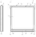
- (A) is a front view of the introductory window to which the hinge arm damper mechanism by one embodiment of this invention was applied
- (b) is a side view. It is a perspective view which shows the state which the shoji fell with respect to the window frame in the introductory window shown in FIG. It is a disassembled perspective view which shows the structure of the shoji falling angle locking mechanism used for the inverted window shown in FIG.
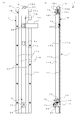
- (A) is a front view of the state which the locking member which comprises the shoji fall angle locking mechanism shown in FIG. 3 engaged with the upper hole
- (b) is a longitudinal cross-sectional view of the state.
- (A) is a front view of the state which the locking member which comprises the shoji fall angle locking mechanism shown in FIG.
- FIG. 7 is an exploded perspective view showing the structure of a hinge arm damper mechanism according to one embodiment.
- (A) is a side view of the hinge arm damper mechanism shown in FIG.
- (b) is a plan view
- (c) is a plan view showing the arrangement of each component in the state before operation of the hinge arm damper mechanism
- d) is a top view which shows arrangement
- FIG. 1 (a) is a front view and FIG. 1 (b) is a side view of an inverted window 2 to which a hinge arm damper mechanism 31, 31 described later according to one embodiment of the present invention is applied.
- the inward turning window 2 is configured by fitting the shoji 4 to the window frame 3.
- the window frame 3 includes a left vertical frame 3a standing vertically to the left, a right vertical frame 3b standing vertically to the right, an upper frame 3c connecting between the upper ends of the left vertical frame 3a and the right vertical frame 3b, and A lower frame 3d for connecting between the lower ends of the vertical frame 3a and the right vertical frame 3b is structured and configured.
- Shoji 4 has a left vertical weir 4a standing vertically to the left, a right vertical weir 4b standing vertically to the right, an upper weir 4c connecting between the upper ends of the left vertical weir 4a and the right vertical weir 4b, and a left vertical
- a lower rod 4d is formed in a frame so as to connect between the lower ends of the rod 4a and the right vertical rod 4b.
- the shoji 4 clamps the glass plate 5 between the left longitudinal weir 4a, the right longitudinal weir 4b, the upper weir 4c and the lower weir 4d.
- the window frame 3 and the shoji 4 are connected by hinge arms 6, 6 between the left vertical frame 3a and the left vertical weir 4a, and between the right vertical frame 3b and the right vertical weir 4b.
- FIG. 2 is a perspective view showing a state in which the sliding door 4 is supported by the hinges 6 and 6 connecting the window frame 3 and the sliding door 4 and the sliding door 4 is folded in half with respect to the window frame 3.
- the same reference numerals as in FIG. 1 denote the same parts in FIG.
- the upper edge 4c side of the shoji 4 is inclined to the indoor side centering on the side contacting the lower frame 3d of the lower edge 4d, and the predetermined angle is set by the lower edge locking mechanism 1,1 connected to each end of the hinge arms 6,6. It is kept in the fallen state.
- the shoji folding angle locking mechanism 1, 1 is the opposite surface of the left vertical hook 4a of the shoji 4 facing the left vertical frame 3a of the window frame 3, and the right vertical frame 3b of the window frame 3 Provided on the opposite surface facing the
- the respective shoji folding angle lock mechanisms 1, 1 have the same configuration, and hereinafter, only one provided on the left longitudinal weir 4 a of the shoji 4 will be described.
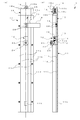
- FIG. 3 is an exploded perspective view showing the structure of the shoji fall angle lock mechanism 1.
- FIG. 4 (a) is a front view of the shoji fall angle lock mechanism 1
- FIG. 4 (b) is a longitudinal sectional view broken at the center line shown in FIG. 4 (a).
- the sliding door locking angle locking mechanism 1 includes the slide rail 11, the slide piece 12, the lock member 13, the lock spring 14 (see FIG. 4B), the lock release plate 15, the latch member 16, the latch spring 17, the rail cap 18, and The control lever 19 is provided.
- the slide rail 11 is made of an aluminum material, and is embedded in a slit formed on an opposing surface of the left vertical weir 4a facing the left vertical frame 3a, and attached to the left vertical weir 4a.
- the side plates of the left vertical weir 4a forming this slit are fastened to the mounting surfaces 11a and 11a of the slide rail 11 with five countersunk screws 20 respectively, and the side surfaces sandwiching the slide piece 12 of the slide rail 11 11b and 11b are flush with the side plate side surface of the left vertical weir 4a. Further, as shown in FIG.
- the rail cap 18 is attached to the upper rim 4c side end portion 11c of the shoji 4 of the slide rail 11 with two flathead screws 21 and 21, but the rail cap 18 has its upper end surface 18a. Is provided flush with the upper surface of the upper weir 4c.
- the two countersunk screws 21 and 21 are passed through the two through holes 18 b and 18 b formed in the rail cap 18 and screwed into the female screw holes 11 i and 11 i formed in the end 11 c of the slide rail 11.
- the rail cap 18 enclosed by blowing in FIG. 3 shows the state which looked down on the original rail cap 18 from diagonally opposite upper side.
- the slide rail 11 has tracks 11d and 11e extending along the longitudinal direction of the left vertical weir 4a and a slide surface 11f.
- the track 11d is constituted by a pair of opposed grooves formed in a wide width to face the columnar part forming the side surfaces 11b and 11b
- the track 11e is constituted by a pair of opposed grooves formed in a narrow width .
- the slide piece 12 linearly moves along the formation direction of the raceway 11d by fitting the pair of convex portions 12a, 12a formed on both sides to the groove of the raceway 11d.
- the lock release plate 15 linearly moves along the formation direction of the track 11 e by fitting the both sides thereof to the groove of the track 11 e.
- the slide surface 11f is formed on the surface facing the left vertical frame 3a of the connecting portion that connects between the columnar portions forming the side surfaces 11b and 11b, and is positioned at the back of the groove forming the tracks 11d and 11e.
- Holes 11g and 11h open at predetermined positions corresponding to the falling angle of the shoji 4 on the slide surface 11f.
- the upper hole 11g opens at a position corresponding to the middle tilt angle of the shoji 4 and the lower hole 11h opens at a position corresponding to the maximum tilt angle of the shoji 4.
- the slide piece 12 attached to the slide rail 11 so as to be movable along the track 11d is formed by aluminum die casting, and constitutes a slide member.
- the slide piece 12 pivotally supports one end of the hinge arm 6 on the side of the shoji 4 on a shaft portion 12b formed to project in a cylindrical shape on the side surface.
- One end of the hinge arm 6 is sandwiched by the resin washers 22 and 23, and a hole formed at the one end is passed through the shaft 12 b together with the resin washers 22 and 23.
- the truss screw 24 is screwed into the female screw formed in the shaft portion 12 b, and one end of the hinge arm 6 is prevented from coming off from the shaft portion 12 b together with the resin washers 22 and 23. It is swingably supported by the shaft portion 12b.
- the slide piece 12 moves the track 11 d in one direction away from the end 11 c by swinging one end of the hinge arm 6 by the weight of the hinge arm 6 when the shoji 4 is opened.
- the slide piece 12 has a cavity on the side facing the slide surface 11 f, and the lock member 13 is accommodated in the cavity.
- the lock member 13 is formed by aluminum die casting in the same manner as the slide piece 12.
- the lock member 13 is supported by a pair of holes 12c and 12c in which the pin 25 is passed through the through hole 13a formed at one end and the both ends of the pin 25 are opposed to the upper end side of the slide piece 12 Is rotatably attached to the slide piece 12.
- the lock member 13 has one end rotatably attached to the slide piece 12 in this manner, and moves the track 11 d in one direction together with the slide piece 12 with the other end at the top.
- a lock spring 14 is provided between the slide piece 12 and the lock member 13.
- One end of the lock spring 14 is fitted in a groove 13b provided in the abdomen of the lock member 13, and the other end of the lock member 13 is biased toward the slide surface 11f.
- the other end of the lock member 13 slides on the slide surface 11f when the slide piece 12 moves in one direction, and engages with the holes 11g and 11h formed in the slide surface 11f.
- the other end of the lock member 13 is inclined such that the angle in contact with the slide surface 11 f is acute.
- the holes 11 g and 11 h are formed in the slide surface 11 f along the slide direction in accordance with the plurality of tilt angles of the shoji 4.
- FIG. 4 shows a state in which the other end of the lock member 13 is engaged with the upper hole 11g
- FIG. 5 shows a state in which the other end of the lock member 13 is engaged with the lower hole 11h
- 5 (a) is a front view of the shoji fall angle lock mechanism 1 at this time
- FIG. 5 (b) is a longitudinal sectional view broken at the center line shown in FIG. 5 (a). The same code is attached.
- the other end of the lock member 13 engages with the holes 11g and 11h at a plurality of locations on the slide surface 11f, and the slide piece 12 is locked to a plurality of locations on the track 11d.
- one end of the hinge arm 6 is held at multiple angles at multiple levels.
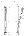
- 6 (a) shows the hinge arm 6 standing up and the window frame 3 being closed by the shoji 4.
- FIG. 6 (b) shows that the hinge arm 6 falls to an intermediate angle and the shoji 4 is half-opened.
- FIG. 7 shows a state in which the hinge arm 6 is at a maximum angle and the shoji 4 is fully open.
- the shoji 4 is held at a plurality of tilting angles by the hinge arm 6 and falls down in multiple steps, it is possible to select a plurality of opening amounts of the inward turning window 2.
- the lock release plate 15 is made of a stainless steel plate, and is guided by the track 11e and attached to the slide rail 11 so as to be movable along the slide surface 11f.
- the lock release plate 15 moves along the slide surface 11 f between the lock release position and the retraction position.
- the unlocking position is an operation position in which the tip 15a positioned at the front when the unlocking plate 15 moves in one direction pushes the other end of the locking member 13 engaged with the hole 11g from the hole 11g.
- the retreat position is an initial position where the tip 15a does not push up the other end of the lock member 13 from the hole 11g.
- the unlocking plate 15 shown in FIG. 4 and FIG. 5 shows the state in this retracted position.
- the latch spring 17 biases the lock release plate 15 along the slide surface 11 f to the retracted position.
- the rear end 15 b is provided to project from the rail cap 18 as shown in FIGS. 4 and 5.
- the rear end 15b of the unlocking plate 15 is bent to form a bent portion.
- the pin 26 is passed through the pair of holes formed in the bent portion and the through holes formed in the resin latch member 16, and the latch member 16 is attached to the rear end 15b by being pinched by the bent portion.
- the rear end 15b to which the latch member 16 is attached is retractably housed in a space 18c formed in a rectangular shape in the resin rail cap 18, and the side surfaces 18d and 18d are closed by the latch cover 18e.
- the attachment of the latch cover 18e to the side surfaces 18d, 18d is performed by a pair of countersunk screws 27, 27.
- a slide groove 18f is formed between the blocks forming the side faces 18d, 18d, and the portion directly below the rear end 15b of the lock release plate 15 is fitted into the slide groove 18f, and the movement of the lock release plate 15 is guided. Ru.
- the bent portion formed at the rear end 15b of the lock release plate 15 forms a first convex portion, and when the lock release plate 15 moves downward, contacts a surface 18g formed in a rectangular shape in the space 18c.
- the surface 18g abuts on a first convex portion provided on the rear end 15b of the lock release plate 15, and constitutes a surface that defines the lock release position of the lock release plate 15.
- convex portions 15c, 15c protruding to both sides are provided as second convex portions.
- the convex portions 15 c and 15 c abut on the bottom surface of the rail cap 18.
- the bottom surface of the rail cap 18 constitutes a surface that abuts on the second convex portion to define the retracted position of the lock release plate 15.
- the lock release plate 15 is guided by a slide groove 18 f formed in the rail cap 18 and a track 11 e formed in the slide rail 11 to move the slide surface 11 f.
- the unlocking plate 15 has a length such that the tip 15a reaches the hole 11g located closer to one of the plurality of holes 11g and 11h than the farthest hole 11h. Movement of the unlocking plate 15 in one direction against the biasing force of the latch spring 17 is provided at the rear end 15b of the unlocking plate 15 on the surface 18g of the rail cap 18 which determines the unlocking position of the unlocking plate 15. When the bent portion abuts, it is stopped at the unlocking position.
- the lock release plate 15 pushes up the other end of the lock member 13 engaged with the hole 11g from the hole 11g of the slide surface 11f to the hole 11g of the other end of the lock member 13 at the lock release position. Disengage the. Further, the movement of the unlocking plate 15 in the direction opposite to the one direction is achieved by the convex portions 15c, 15c of the unlocking plate 15 coming into contact with the bottom surface of the rail cap 18 which determines the retreat position of the unlocking plate 15. It is stopped at the retreat position, and the unlocking plate 15 is held at the retreat position by the biasing force of the latch spring 17.
- a columnar support 18 h is provided which is fitted to one end of the latch spring 17 to support one end thereof.
- the other end of the latch spring 17 abuts on the bottom surface of the latch member 16, and the elastic force causes the latch member 16 to project from the upper end surface 18 a of the rail cap 18, that is, the upper surface of the upper collar 4 c of the shoji 4.
- the latch member 16 is provided at the rear end 15b of the lock release plate 15 so that the surface on the outdoor side is curved so as to protrude from the outer shape of the rear end 15b of the lock release plate 15 as shown in FIGS. .
- the latch member 16 is urged in a direction to project from the upper rod 4c of the shoji 4 by the urging force of the latch spring 17, and the outer side surface of the latch member 16 abuts on the upper frame 3c of the window frame 3 when the shoji 4 is closed. As it is pushed down, it falls to the upper collar 4 c side of the shoji 4 and is accommodated in the space 18 c formed in the rail cap 18 together with the latch spring 17. Thereafter, when the latch member 16 reaches the latch receiver 29 (see FIG.
- the control lever 19 is formed by bending a stainless steel plate, and is extended from the lock release plate 15 to the indoor side as shown in FIG.
- the control lever 19 constitutes a lock release operating member that moves the lock release plate 15 along the slide surface 11 f to the lock release position against the biasing force of the latch spring 17.
- the unlocking plate 15 is always biased by the latch spring 17 and held at a retracted position where the leading end 15a located at the leading end does not reach the hole 11g when moving in one direction.
- the operation lever 19 is operated, and the unlocking plate 15 resists the biasing force of the latch spring 17 along the slide surface 11f.
- the tip end 15a of the unlocking plate 15 reaches the hole 11g located closer to one of the plurality of holes 11g and 11h than the farthest hole 11h. Then, the tip end 15a of the lock release plate 15 pushes up the other end of the lock member 13 from the hole 11g.
- the engagement state between the hole 11g excluding the hole 11h farthest from the unlocking plate 15 and the other end of the locking member 13 is thus the unlocking plate It can be solved by the fifteen tips 15a.
- each engagement state between each hole and the other end of the lock member 13 is one position closer than the hole 11 h farthest from the hole 11 g closest to the lock release plate 15 in the retracted position.
- the holes are released by the tip 15a of the unlocking plate 15 in the order of separation from the unlocking plate 15 in the retracted position.
- the falling angle shown in FIG. 7, which is determined by the position of the slide piece 12 engaged with the farthest hole 11 h and the other end of the lock member 13, is most inclined.
- one hinge arm 6 is connected to a hinge arm damper mechanism 31 shown in FIGS. 6 and 7 provided on the surface of the left vertical frame 3a of the window frame 3 facing the left vertical rod 4a of the shoji 4 It is done.
- the other end of the hinge arm 6 is connected to a similar hinge arm damper mechanism 31 provided on the surface of the right vertical frame 3b of the window frame 3 facing the right vertical rod 4b of the shoji 4.
- Each hinge arm 6, 6 has its rotational torque applied to the hinge arms 6, 6 buffered by the hinge arm damper mechanism 31, 31.
- FIG. 8 is an exploded perspective view of the hinge arm damper mechanism 31.
- FIG. 9 (a) is a side view of the hinge arm damper mechanism 31
- FIG. 9 (b) is a plan view
- FIG. 9 (c) is a plan view showing the arrangement of components before operation of the hinge arm damper mechanism 31.
- the same figure (d) is a top view which shows arrangement
- the hinge arm damper mechanism 31 includes a pinion gear 32, a pair of racks 33, 33, two sets of heavy load springs 34, 34, a pair of slide bars 35, 35, and a housing.
- the housing comprises a box-like case 36 and a plate-like cover 37.
- the pinion gear 32, the pair of racks 33, 33, the two sets of heavy load springs 34, 34, and the pair of slide bars 35, 35 are shown in FIGS. It is stored.
- a cover 37 is attached to a case 36 containing these components by a countersunk screw 38a and a countersunk screw 38b, and the components are sealed as shown in FIGS. 9 (a) and 9 (b).
- the pinion gear 32 is rotatably supported by the housing by the shaft portions 32a on both sides fitted into the opening 37a of the cover 37 and the opening 36e of the case 36.
- the opening 37a and the opening 36e constitute a gear support.
- a hexagonal columnar connecting portion 32 b is formed coaxially with the shaft portion 32 a on the side shaft portion 32 a on the cover 37 side.
- the other end of the hinge arm 6 is fitted to the connecting portion 32b, and the hinge arm 6 rotates around the other end.
- the pair of racks 33, 33 are provided at positions facing each other across the rotation center of the pinion gear 32, and, upon receiving the rotation of the pinion gear 32, go straight in the direction away from each other.
- the racks 33, 33 mesh with the pinion gear 32 to convert the rotational movement of the pinion gear 32 into a linear movement.
- guide portions 36a, 36a for guiding the rectilinear movement of the racks 33, 33 are formed by the inner wall of the case 36 in contact with the side surfaces of the racks 33, 33.
- a plurality of reinforcing ribs 36d are formed on the outer side of the case 36 where the guide portions 36a and 36a are formed, in a direction intersecting the direction of the linear movement of the racks 33 and 33.
- the racks 33, 33 have extending portions 33a, 33a in a direction intersecting with the direction in which the racks 33 move straight.
- a slide bar 35 and springs 34, 34 are accommodated between the extensions 33a, 33a and the end walls 36b, 36b of the case 36.
- Each slide bar 35 is formed in parallel with the extension 33a, and a contact surface 35a that contacts the extension 33a is formed on the rack 33 side. Further, fitting portions 35b, 35b fitted to one end portions of the springs 34, 34 are formed side by side on the springs 34, 34 side.
- Each slide bar 35 constitutes a restricting member disposed between the extension 33 a and one end of each spring 34, 34.
- Each pair of springs 34 and 34 is provided at a position opposite to each other with the racks 33 and 33 centered on the rotation center of the pinion gear 32.
- the springs 34, 34 are formed by compression coil springs, and constitute elastic members that brake the rectilinear movement of the racks 33, 33 in the separating direction.
- Each spring 34 receives the force of movement of the rack 33 at one end from the extension 33 a through the slide bar 35.
- the end wall 36 b of the case 36 constitutes a reaction force support portion, and receives a reaction force generated on the springs 34 by braking the linear movement of the rack 33.
- two springs 34 are provided in parallel, and the motion force of the rack 33 is shared and received at each one end of the springs 34, 34.
- the springs 34, 34 are separated by a partition 36c of the case 36 to prevent buckling.
- the rotational torque applied to the hinge arm 6 is transmitted to the racks 33, 33 via the rotational movement of the pinion gear 32, and converted into the linear movement of the racks 33, 33.
- This linear movement of the racks 33, 33 is braked by the springs 34, 34. Therefore, the rotational torque applied to the hinge arm 6 is reliably buffered by the braking force of the springs 34, 34. Therefore, by applying the hinge arm damper mechanism 31 having the above configuration to the hinge arm 6 of the inverted window 2, it is possible to reliably exhibit the damper effect according to the braking force of the springs 34, 34. Therefore, even if the shoji 4 is large and heavy, an appropriate damper effect is exhibited, and it is possible to sufficiently buffer the rotational torque applied to the hinge arm 6 of the inverted window 2.
- braking force of the spring 34,34 is exhibited according to the deflection amount. Therefore, as shown in FIG. 6B, when the amount of rotation of the hinge arm 6 is small, the distance that the racks 33 and 33 move straight is short and the amount of deflection generated in the springs 34 and 34 is small. The power is small and the force to buffer the rotational torque applied to the hinge arm 6 is weak. On the other hand, when the amount of rotation of the hinge arm 6 increases to the maximum inclination angle of the shoji 4 shown in FIG. 7, the straight distance of the racks 33 and 33 goes straight and the deflections of the springs 34 and 34 increase. The braking forces of the springs 34 and 34 gradually increase, and the force for buffering the rotational torque applied to the hinge arm 6 gradually increases.
- the hinge arm damper mechanism 31 according to the present embodiment to the hinge arm 6 of the inverted window 2, when the amount of opening of the shoji 4 is small and the amount of rotation of the hinge arm 6 is small Although the force is weak, as the opening amount of the shoji 4 increases and the falling angle of the shoji 4 increases, the amount of rotation of the hinge arm increases, and the assisting force for the opening and closing operation of the shoji gradually becomes stronger. Therefore, when opening the shoji 4, the operating force that is increased by the weight of the shoji 4 when opening the shoji 4 can be a light operating force by the assisting force of the hinge arm damper mechanism 31.
- the biasing force of the springs 34 and 34 is added to the operation force for closing the shoji 4 so that the shoji 4 can be closed with a light operation force. Therefore, the operator of the shoji 4 can perform the opening and closing operation of the shoji 4 with a good feeling of operation.
- the damper effect is constant when the shoji 4 is opened and closed because the damper effect is obtained by the resin washer or the wave washer sandwiched by the shaft. For this reason, when closing the shoji 4, operation becomes heavy by damper effects, such as a resin washer, and the operativity with the good feeling of operation like the hinge arm damper mechanism 31 by this embodiment is not obtained.
- the hinge arm damper mechanism 31 since the racks 33 and 33 and the springs 34 and 34 are symmetrically provided at positions facing each other about the rotation center of the pinion gear 32, the rotational movement of the pinion gear 32 is It is converted in a well-balanced manner into linear motion of the racks 33, 33. Therefore, the buffer operation of the hinge arm damper mechanism 31 is stably performed. Further, since the buffer function acts on both sides of the position opposite to the center of rotation of the pinion gear 32, the buffer force is enhanced, and the large rotational torque applied to the hinge arm 6 can be buffered.
- the hinge arm damper mechanism 31 according to the present embodiment, the kinetic force of the racks 33 is stably transmitted to one end of the springs 34 via the extending portions 33a. Therefore, the rotational torque applied to the hinge arm 6 is effectively transmitted to the springs 34 and 34 through the racks 33 and 33, and the braking force of the springs 34 and 34 effectively acts to rotate the hinge arm 6 The torque is more reliably buffered.
- two springs 34, 34 are provided in parallel, and the braking force exerted by the springs 34, 34 in general becomes stronger. It can buffer torque.
- the hinge arm damper mechanism 31 according to the present embodiment, the kinetic force of the racks 33, 33 from the extending portions 33a, 33a is reliably received by the contact surfaces 35a, 35a of the slide bars 35, 35, By the fitting portions 35b of the slide bars 35, the arrangement position is reliably transmitted to one end of each of the springs 34, which are regulated and held side by side. Therefore, the braking force of the springs 34, 34 acts more effectively on the racks 33, 33, and the rotational torque applied to the hinge arm 6 is buffered more reliably.
- the racks 33, 33 receive the guidance from the guide portions 36a, 36a of the case 36 constituting the casing and convert the rotational movement of the pinion gear 32 into a rectilinear movement, but the racks 33, 33 correspond to the guide portions 36a, 36a.
- a reaction force is applied which restricts this linear movement, and a force acts on the guide portions 36a and 36a to distort the housing.
- the reinforcing ribs 36d and 36d are formed on the outer side of the portion where the guide portions 36a and 36a of the housing are formed, and the reinforcing ribs 36d and 36d serve as the housing Opposed to the distorting force. For this reason, even if a force to distort the case is applied to the case from the racks 33, 33, deformation of the case is prevented, and the rotational movement of the pinion gear 32 is surely converted to the linear movement of the racks 33, 33.
- the reinforcing ribs 36d and 36d are formed to rise in the direction perpendicular to the linear movement direction of the racks 33, 33. However, a direction parallel to the linear movement direction of the racks 33 and 33 is described. You may make it form the reinforcement rib which swells up.
- an adjustment member for adjusting the initial braking force of the springs 34, 34 may be provided on the other end side or one end side of the springs 34, 34.
- an adjustment member for example, a plate, a washer, or the like provided on the end walls 36 b and 36 b of the case 36 with the springs 34 and 34 may be mentioned.
- the end wall 36b side of the partition wall 36c is partially removed over a predetermined length, and the position of the plate material abutting on both ends of the springs 34, 34 can be varied in the extension direction of the springs 34, 34. It can also be configured.
- the shock absorbing force exerted by the hinge arm damper mechanism 31 can be easily set to a desired shock absorbing force by adjusting the initial braking force of the springs 34 by the adjusting member. For this reason, it becomes possible to adjust easily to the hinge arm damper mechanism 31 which exhibits the required damper effect.
- the hinge arm damper mechanism 31 the case where two springs 34 and 34 are provided in parallel is described, but three or more springs may be provided in parallel instead of in parallel. It may be configured as follows. In the case where the rack 33 is provided independently, by leaving the spring 34 on the root side of the extension 33a of the rack 33, the rack 33 can receive the rectilinear motion of the rack 33 without tilting, and the efficiency is improved. Power is transmitted to Further, in the hinge arm damper mechanism 31 according to the above embodiment, the respective sets of the springs 34, 34 are provided symmetrically at the opposing position centering on the pinion gear 32, but not provided symmetrically, only on one side of the pinion gear 32. A plurality of or one spring 34 may be provided.
Landscapes
- Engineering & Computer Science (AREA)
- Mechanical Engineering (AREA)
- Closing And Opening Devices For Wings, And Checks For Wings (AREA)
- Wing Frames And Configurations (AREA)
Abstract
L'invention concerne un mécanisme d'amortisseur de bras d'articulation grâce auquel un effet d'amortisseur en réponse à la force de freinage d'un élément élastique se manifeste de manière fiable. Un mécanisme d'amortisseur de bras d'articulation 31 comprend un engrenage à pignons 32, une paire de crémaillères 33, 33, deux ensembles de ressorts de charge lourde 34, 34, une paire de barres coulissantes 35, 35, et un boîtier. Le boîtier comprend un logement en forme de boîte 36 et un couvercle en forme de plaque 37. Le logement 36 accueille l'engrenage à pignons 32, la paire de crémaillères 33, 33, les deux ensembles de ressorts de charge lourde 34, 34, et la paire de barres coulissantes 35, 35. Le couple de rotation appliqué à un bras d'articulation 6 est transmis aux crémaillères 33, 33 par un mouvement de rotation de l'engrenage à pignons 32 et est converti en mouvement linéaire des crémaillères 33, 33. Le freinage est appliqué de manière fiable au mouvement linéaire des crémaillères 33, 33 grâce aux ressorts 34, 34.
Priority Applications (3)
| Application Number | Priority Date | Filing Date | Title |
|---|---|---|---|
| DE112018005430.6T DE112018005430T5 (de) | 2017-11-10 | 2018-11-08 | Scharnierarm-Dämpfungsmechanismus |
| JP2019552375A JP6896257B2 (ja) | 2017-11-10 | 2018-11-08 | ヒンジアームダンパ機構 |
| US16/762,666 US11131134B2 (en) | 2017-11-10 | 2018-11-08 | Hinge arm damper mechanism |
Applications Claiming Priority (2)
| Application Number | Priority Date | Filing Date | Title |
|---|---|---|---|
| JP2017-217837 | 2017-11-10 | ||
| JP2017217837 | 2017-11-10 |
Publications (1)
| Publication Number | Publication Date |
|---|---|
| WO2019093421A1 true WO2019093421A1 (fr) | 2019-05-16 |
Family
ID=66438420
Family Applications (1)
| Application Number | Title | Priority Date | Filing Date |
|---|---|---|---|
| PCT/JP2018/041490 Ceased WO2019093421A1 (fr) | 2017-11-10 | 2018-11-08 | Mécanisme d'amortisseur de bras d'articulation |
Country Status (4)
| Country | Link |
|---|---|
| US (1) | US11131134B2 (fr) |
| JP (1) | JP6896257B2 (fr) |
| DE (1) | DE112018005430T5 (fr) |
| WO (1) | WO2019093421A1 (fr) |
Cited By (2)
| Publication number | Priority date | Publication date | Assignee | Title |
|---|---|---|---|---|
| CN115054477A (zh) * | 2022-05-07 | 2022-09-16 | 浙江豪中豪健康产品有限公司 | 一种带锁扣的四连杆阻尼槽扶手开合机构 |
| EP4361391A1 (fr) * | 2022-10-19 | 2024-05-01 | AS Spilka Industri | Unité de ressort compacte et dispositif de verrouillage pour un système de charnière |
Families Citing this family (1)
| Publication number | Priority date | Publication date | Assignee | Title |
|---|---|---|---|---|
| CN114617399B (zh) * | 2021-12-02 | 2023-08-11 | 丽水市南明文化传媒有限公司 | 一种新材料推广用的移动式宣传装置 |
Citations (4)
| Publication number | Priority date | Publication date | Assignee | Title |
|---|---|---|---|---|
| JPS5844171A (ja) * | 1981-09-08 | 1983-03-15 | 株式会社シユア製作所 | ドアチエツク |
| JP2000045624A (ja) * | 1998-07-29 | 2000-02-15 | Osaka Kanagu Kk | ドアクローザ |
| US20120210540A1 (en) * | 2011-02-22 | 2012-08-23 | Mckibben Aaron Patrick | Door actuator |
| JP2017095902A (ja) * | 2015-11-19 | 2017-06-01 | 美和ロック株式会社 | ドアクローザ |
Family Cites Families (23)
| Publication number | Priority date | Publication date | Assignee | Title |
|---|---|---|---|---|
| US1121084A (en) * | 1913-03-12 | 1914-12-15 | Walter S Finken | Door check and closer. |
| US1627113A (en) * | 1926-01-07 | 1927-05-03 | George C Pearson | Snubber for vehicles |
| US1759474A (en) * | 1928-04-10 | 1930-05-20 | Leland J Volquardsen | Spring hinge for ice-box doors |
| US1872561A (en) * | 1931-08-21 | 1932-08-16 | Fredrick M Franklin | Doorchecking device |
| US1989908A (en) * | 1931-10-03 | 1935-02-05 | Hauserman Co E F | Double acting pivot spring hinge |
| US2505996A (en) * | 1945-08-13 | 1950-05-02 | Modine Mfg Co | Damper to control gas flow |
| GB1214131A (en) * | 1966-11-21 | 1970-12-02 | Brent Metal Works Ltd | Improvements in doors |
| US3746042A (en) * | 1971-11-22 | 1973-07-17 | Swift Sheetmetal Corp | Multi-blade damper |
| JPS5844171B2 (ja) | 1977-08-09 | 1983-10-01 | 川崎重工業株式会社 | 高温熱交換器 |
| JPS54112537A (en) | 1978-02-22 | 1979-09-03 | Nippon Air Brake Co | Pivoted window opening device |
| JPS60457Y2 (ja) | 1979-07-24 | 1985-01-08 | 立山アルミニウム工業株式会社 | 開き窓障子の煽止装置 |
| FR2469542A1 (fr) * | 1979-11-15 | 1981-05-22 | Pont A Mousson | Ferme-porte a double action |
| JPS60138191A (ja) | 1983-12-02 | 1985-07-22 | 日本軽金属株式会社 | 窓開放保持装置 |
| ES2012171A6 (es) * | 1988-12-16 | 1990-03-01 | Hidro Domestics S A | Mecanismo hidraulico de transmision. |
| DE19919012A1 (de) * | 1999-04-27 | 2000-11-02 | Scheer Michael | Verfahren zur Überwachung von Not-Aus-Befehlseinrichtungen |
| US6681525B1 (en) * | 2000-11-15 | 2004-01-27 | David Edmond Dudley | Handicapped train-station gate |
| AT412183B (de) * | 2001-01-25 | 2004-11-25 | Blum Gmbh Julius | Dämpfeinrichtung für bewegbare möbelteile |
| DE20209120U1 (de) * | 2002-06-12 | 2003-10-16 | Hemscheidt Fahrwerktechnik GmbH & Co., 42781 Haan | Federungseinrichtung für Kraftfahrzeuge |
| DE10228399A1 (de) * | 2002-06-25 | 2004-01-15 | Daimlerchrysler Ag | Staufach für ein Fahrzeug |
| ITMI20050181A1 (it) * | 2005-02-09 | 2006-08-10 | Effegi Brevetti Srl | Dispositivo di apertura-chiusura di un'anta a ribalta di un mobile |
| JP2012225054A (ja) * | 2011-04-20 | 2012-11-15 | Daiken Co Ltd | 引戸の引き込み装置 |
| DE102012107522B4 (de) * | 2012-08-16 | 2015-09-24 | Reinhold Schulte | Fahrzeugtürantrieb mit Zahnstange |
| JP2017066633A (ja) | 2015-09-28 | 2017-04-06 | 大和ハウス工業株式会社 | 窓構造 |
-
2018
- 2018-11-08 US US16/762,666 patent/US11131134B2/en active Active
- 2018-11-08 WO PCT/JP2018/041490 patent/WO2019093421A1/fr not_active Ceased
- 2018-11-08 DE DE112018005430.6T patent/DE112018005430T5/de not_active Withdrawn
- 2018-11-08 JP JP2019552375A patent/JP6896257B2/ja active Active
Patent Citations (4)
| Publication number | Priority date | Publication date | Assignee | Title |
|---|---|---|---|---|
| JPS5844171A (ja) * | 1981-09-08 | 1983-03-15 | 株式会社シユア製作所 | ドアチエツク |
| JP2000045624A (ja) * | 1998-07-29 | 2000-02-15 | Osaka Kanagu Kk | ドアクローザ |
| US20120210540A1 (en) * | 2011-02-22 | 2012-08-23 | Mckibben Aaron Patrick | Door actuator |
| JP2017095902A (ja) * | 2015-11-19 | 2017-06-01 | 美和ロック株式会社 | ドアクローザ |
Cited By (3)
| Publication number | Priority date | Publication date | Assignee | Title |
|---|---|---|---|---|
| CN115054477A (zh) * | 2022-05-07 | 2022-09-16 | 浙江豪中豪健康产品有限公司 | 一种带锁扣的四连杆阻尼槽扶手开合机构 |
| EP4361391A1 (fr) * | 2022-10-19 | 2024-05-01 | AS Spilka Industri | Unité de ressort compacte et dispositif de verrouillage pour un système de charnière |
| DK182135B1 (en) * | 2022-10-19 | 2025-09-03 | A/S Spilka Ind | Compact spring unit and locking device for a hinge |
Also Published As
| Publication number | Publication date |
|---|---|
| JP6896257B2 (ja) | 2021-06-30 |
| DE112018005430T5 (de) | 2020-07-16 |
| US20210123282A1 (en) | 2021-04-29 |
| US11131134B2 (en) | 2021-09-28 |
| JPWO2019093421A1 (ja) | 2020-12-24 |
Similar Documents
| Publication | Publication Date | Title |
|---|---|---|
| JP5364162B2 (ja) | 扉開閉装置 | |
| US9803405B2 (en) | Adjustable snap-acting hinge | |
| CA2832778A1 (fr) | Dispositif de verrouillage pour un dispositif de sortie pour une porte | |
| WO2019093421A1 (fr) | Mécanisme d'amortisseur de bras d'articulation | |
| EP3662125B1 (fr) | Charnière dotée de dispositif d'ouverture pour meubles | |
| CN102027181A (zh) | 门开关用支撑条 | |
| TW201311991A (zh) | 鉸鏈 | |
| JP6941360B2 (ja) | 倒れ窓の障子倒れ角ロック機構 | |
| US3802124A (en) | Rocking-swinging window | |
| IT202000027933A1 (it) | Cerniera per mobili con comando per un dispositivo di controllo del movimento | |
| IT202000027942A1 (it) | Cerniera invisibile per mobili | |
| IT202000027939A1 (it) | Cerniera per mobili | |
| US20230323714A1 (en) | Friction hinge for outward opening top hung windows | |
| US8677566B2 (en) | Hinge for doors or wings | |
| EP2761118B1 (fr) | Dispositif de sécurité pour empêcher la fermeture brutale d'un élément mobile | |
| CN110439432B (zh) | 一种用于家具的同步调节机构 | |
| JP4881700B2 (ja) | 内倒し窓の傾斜角度調整装置及びこれを備えた内倒し窓 | |
| KR102083056B1 (ko) | 미서기 창호용 안전감속장치 | |
| EP3714123A1 (fr) | Dispositif de levage comprenant un essieu de système de traîneau et une fenêtre de toit comprenant un tel dispositif de levage | |
| EP2551429B1 (fr) | Dispositif d'ouverture antipanique avec loquet coulissant | |
| EP3489442B1 (fr) | Fenêtre ou porte comprenant un système de verrouillage | |
| US2545279A (en) | Combined stay and device for opening and closing windows and like members | |
| WO2007015077A1 (fr) | Fermeture anti-panique | |
| JP2010116757A (ja) | ドアガード装置 | |
| JP7215335B2 (ja) | スライディングウォール |
Legal Events
| Date | Code | Title | Description |
|---|---|---|---|
| 121 | Ep: the epo has been informed by wipo that ep was designated in this application |
Ref document number: 18876612 Country of ref document: EP Kind code of ref document: A1 |
|
| DPE1 | Request for preliminary examination filed after expiration of 19th month from priority date (pct application filed from 20040101) | ||
| ENP | Entry into the national phase |
Ref document number: 2019552375 Country of ref document: JP Kind code of ref document: A |
|
| 122 | Ep: pct application non-entry in european phase |
Ref document number: 18876612 Country of ref document: EP Kind code of ref document: A1 |