WO2019093444A1 - Film optique stratifié et dispositif d'affichage électroluminescent organique - Google Patents
Film optique stratifié et dispositif d'affichage électroluminescent organique Download PDFInfo
- Publication number
- WO2019093444A1 WO2019093444A1 PCT/JP2018/041559 JP2018041559W WO2019093444A1 WO 2019093444 A1 WO2019093444 A1 WO 2019093444A1 JP 2018041559 W JP2018041559 W JP 2018041559W WO 2019093444 A1 WO2019093444 A1 WO 2019093444A1
- Authority
- WO
- WIPO (PCT)
- Prior art keywords
- circularly polarized
- polarized light
- layer
- separation layer
- liquid crystal
- Prior art date
- Legal status (The legal status is an assumption and is not a legal conclusion. Google has not performed a legal analysis and makes no representation as to the accuracy of the status listed.)
- Ceased
Links
Images

Classifications
-
- G—PHYSICS
- G02—OPTICS
- G02B—OPTICAL ELEMENTS, SYSTEMS OR APPARATUS
- G02B5/00—Optical elements other than lenses
- G02B5/30—Polarising elements
- G02B5/3016—Polarising elements involving passive liquid crystal elements
-
- H—ELECTRICITY
- H10—SEMICONDUCTOR DEVICES; ELECTRIC SOLID-STATE DEVICES NOT OTHERWISE PROVIDED FOR
- H10K—ORGANIC ELECTRIC SOLID-STATE DEVICES
- H10K50/00—Organic light-emitting devices
- H10K50/80—Constructional details
- H10K50/86—Arrangements for improving contrast, e.g. preventing reflection of ambient light
-
- G—PHYSICS
- G09—EDUCATION; CRYPTOGRAPHY; DISPLAY; ADVERTISING; SEALS
- G09F—DISPLAYING; ADVERTISING; SIGNS; LABELS OR NAME-PLATES; SEALS
- G09F9/00—Indicating arrangements for variable information in which the information is built-up on a support by selection or combination of individual elements
-
- G—PHYSICS
- G09—EDUCATION; CRYPTOGRAPHY; DISPLAY; ADVERTISING; SEALS
- G09F—DISPLAYING; ADVERTISING; SIGNS; LABELS OR NAME-PLATES; SEALS
- G09F9/00—Indicating arrangements for variable information in which the information is built-up on a support by selection or combination of individual elements
- G09F9/30—Indicating arrangements for variable information in which the information is built-up on a support by selection or combination of individual elements in which the desired character or characters are formed by combining individual elements
-
- H—ELECTRICITY
- H05—ELECTRIC TECHNIQUES NOT OTHERWISE PROVIDED FOR
- H05B—ELECTRIC HEATING; ELECTRIC LIGHT SOURCES NOT OTHERWISE PROVIDED FOR; CIRCUIT ARRANGEMENTS FOR ELECTRIC LIGHT SOURCES, IN GENERAL
- H05B33/00—Electroluminescent light sources
- H05B33/02—Details
-
- H—ELECTRICITY
- H10—SEMICONDUCTOR DEVICES; ELECTRIC SOLID-STATE DEVICES NOT OTHERWISE PROVIDED FOR
- H10K—ORGANIC ELECTRIC SOLID-STATE DEVICES
- H10K59/00—Integrated devices, or assemblies of multiple devices, comprising at least one organic light-emitting element covered by group H10K50/00
- H10K59/10—OLED displays
- H10K59/12—Active-matrix OLED [AMOLED] displays
-
- H—ELECTRICITY
- H10—SEMICONDUCTOR DEVICES; ELECTRIC SOLID-STATE DEVICES NOT OTHERWISE PROVIDED FOR
- H10K—ORGANIC ELECTRIC SOLID-STATE DEVICES
- H10K59/00—Integrated devices, or assemblies of multiple devices, comprising at least one organic light-emitting element covered by group H10K50/00
- H10K59/80—Constructional details
- H10K59/8791—Arrangements for improving contrast, e.g. preventing reflection of ambient light
Definitions
- the present invention relates to an optical laminate film and an organic electroluminescent display device.
- Organic electro luminescence Organic EL (Electro Luminescence) (OLED (Organic Light Emitting Diode)
- OLED Organic Light Emitting Diode
- the organic EL substrate since the organic EL substrate has a high surface reflectance, it reflects external light particularly in a bright environment, thereby deteriorating the contrast. Therefore, in the organic EL display device, an antireflective film including a polarizer and a retardation layer ( ⁇ / 4 plate) is disposed. However, in this configuration, although the deterioration of the contrast due to the reflection of the organic EL substrate can be prevented, the light emitted from the organic EL element is absorbed by the polarizer of the antireflective film, so the luminance is lowered. The performance of the light emitting element or the like has not been sufficiently exhibited.
- a cholesteric liquid crystal layer formed by fixing a cholesteric liquid crystal phase between an antireflective film and an organic EL light emitting element Patent Document 1.
- the cholesteric liquid crystal layer is known to have a function of selectively reflecting a specific circularly polarized component in a specific wavelength range. Therefore, by disposing a cholesteric liquid crystal layer between the antireflective film and the organic EL substrate, the circularly polarized light component that would otherwise be absorbed by the polarizer is reflected by the cholesteric liquid crystal layer, and the organic EL substrate is Then, by reflecting again, it can be converted to a circularly polarized component which is not absorbed by the polarizer and used. As a result, it is possible to suppress the decrease in luminance due to the antireflection film consisting of a polarizer and a ⁇ / 4 plate.
- the present inventors produce a cholesteric liquid crystal layer that selectively reflects blue light, and an organic EL display having the above-described configuration.
- the device was considered.
- a large-area organic EL display device the reflection color when observed from the front at the time of extinction differs depending on the area, and a large problem may occur.
- a 55-inch TV screen is 121.5 ⁇ 68.5 cm in size, and it has been found that it is an important task to realize uniform color over such a wide range.
- the present invention is an optical laminated film having a polarizer, a retardation layer, and a circularly polarized light separating layer, wherein the optical laminated film having a uniform reflection color even in a large size, and a large size using the optical laminated film
- the present invention has the following configuration.
- At least a polarizer, a retardation layer, and a circularly polarized light separation layer are disposed in this order,
- the in-plane retardation Re (550) of the retardation layer is 120 to 160 nm,
- the polarizer and the retardation layer are disposed such that the transmission axis of the polarizer and the slow axis of the retardation layer are 45 ° ⁇ 10 °
- the circularly polarized light separation layer is a cholesteric liquid crystal layer containing a liquid crystal compound as a main component and having a cholesteric liquid crystal phase fixed, Assuming that n is the average refractive index of the liquid crystal compound forming the circularly polarized light separation layer, ⁇ n is birefringence of the liquid crystal compound forming the circularly polarized light separation layer, and ⁇ is the selective reflection center wavelength of the circularly polarized light separation layer.
- the in-plane retardation Re (550) of the circularly polarized light separation layer is 0.5 ⁇ ReMax ⁇ Re (550) ⁇ ReMax Optical laminated film characterized by satisfying. [2] The in-plane retardation Re (550) of the circularly polarized light separation layer is 0.7 ⁇ ReMax ⁇ Re (550) ⁇ ReMax Optical laminated film as described in [1] which satisfy
- An optical laminated film according to any one of [1] to [8] and an organic electroluminescent light emitting device An organic electroluminescent display device, wherein an optical laminated film and an organic electroluminescent light emitting device are disposed such that the circularly polarized light separating layer is sandwiched between the retardation layer and the organic electroluminescent light emitting device.
- an optical laminated film which is excellent in uniformity of reflective color even in a large size, and an organic EL display device excellent in uniformity of reflective color in extinction even in a large size. Can be provided.
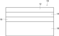
- FIG. 1 is a conceptual view showing an example of the organic EL display device of the present invention.
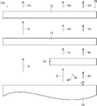
- FIG. 2 is a conceptual diagram for explaining the operation of the organic EL display device shown in FIG.
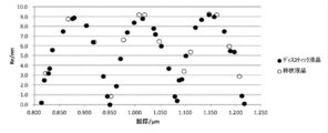
- FIG. 3 is a graph showing that the color changes periodically with respect to the film thickness of the circularly polarized light separation layer.
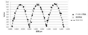
- FIG. 4 is a graph showing that Re changes periodically with respect to the film thickness of the circularly polarized light separation layer.
- FIG. 5 is a graph showing that a simulation result indicating that Re periodically changes with respect to the film thickness of the circularly polarized light separation layer matches an actual measurement value.
- Re ( ⁇ ) and Rth ( ⁇ ) respectively indicate in-plane retardation at the wavelength ⁇ and retardation in the thickness direction. Unless otherwise stated, the wavelength ⁇ is 550 nm.
- R0 ((lambda)) is displayed as a numerical value calculated by AxoScan, it means Re ((lambda)).
- NAR-4T Abbe refractive index
- ⁇ sodium lamp
- values of Polymer Handbook JOHN WILEY & SONS, INC
- catalogs of various optical films can be used.
- the values of the average refractive index of the main optical films are exemplified below: cellulose acylate (1.48), cycloolefin polymer (1.52), polycarbonate (1.59), polymethyl methacrylate (1.49), And polystyrene (1.59).
- visible light is light of wavelengths visible to human eyes among electromagnetic waves, and represents light in a wavelength range of 380 to 780 nm.
- Nonvisible light is light in a wavelength range of less than 380 nm or in a wavelength range of more than 780 nm.
- light in the wavelength range of 420 to 490 nm is blue light
- light in the wavelength range of 495 to 570 nm is green light
- the light is red light.
- FIG. 1 schematically shows an example of the organic electroluminescent display device of the present invention.
- the organic electroluminescent display device is also referred to as an organic EL display device.
- the organic EL display device 10 of the present invention shown in FIG. 1 has a polarizer 12, a retardation layer 14, a circularly polarized light separation layer 16, and an organic electroluminescent light emitting element 18 in this order from the viewing side.
- the organic electroluminescent light emitting device is also referred to as an organic EL light emitting device.
- the polarizer 12 and the retardation layer 14 constitute an antireflective film
- the polarizer 12, the retardation layer 14 and the circularly polarized light separating layer 16 constitute an optical laminate film of the present invention.
- the present invention can improve the luminance of display in the organic EL display device 10, can prolong the life of the organic EL element, and can also suppress the reflection of external light.
- the circularly polarized light separation layer 16 is a cholesteric liquid crystal layer.
- the cholesteric liquid crystal layer is a layer having a cholesteric liquid crystal structure formed by fixing a cholesteric liquid crystal phase.
- the cholesteric liquid crystal layer selectively reflects a specific circularly polarized component in a specific wavelength range.
- the selective reflection center wavelength of the circularly polarized light separation layer 16 is not limited, but the circularly polarized light separation layer 16 (cholesteric liquid crystal layer) preferably has a selective reflection center wavelength in the wavelength range of blue light. That is, the circularly polarized light separation layer 16 preferably reflects blue light selectively.
- the circularly polarized light separation layer 16 more preferably has a selective reflection center wavelength in the range of 430 to 480 nm.
- the circularly polarized light separation layer 16, which is a cholesteric liquid crystal layer, is substantially a C plate because the chirality of the cholesteric liquid crystal layer is averaged for light other than in the reflection region.
- light incident from an oblique direction has a so-called short wave shift (blue shift) in which the reflection range is shifted to the short wavelength side. Act as a plate.
- the organic EL light emitting element has a difference in energy required to emit light of each color, and in general, the blue light emitting element degrades faster than the green and red light emitting elements. Therefore, in consideration of the lifetime of the blue light emitting element, measures such as suppressing the light emission amount (output) of the light emitting element of each color are taken.
- the luminance of blue light can be improved, and the overall display luminance can be improved, and the length of the light emitting element of blue light that is rapidly deteriorated It is possible to extend the lifetime and to prolong the lifetime of the organic EL display device.
- a circularly polarized light separation layer 16 which is a cholesteric liquid crystal layer having a wavelength is disposed.
- the retardation layer 14 a + A plate having a positive Rth (550) value or a B plate having a positive Rth (550) value is used, and a cholesteric liquid crystal layer of the circularly polarized light separation layer 16 is More preferred is a combination using a cholesteric liquid crystal layer composed of a discotic liquid crystal compound. This is because the cholesteric liquid crystal layer made of a discotic liquid crystal compound functions as a + C plate except in the reflection region.
- the retardation layer 14 ( ⁇ / 4 film) preferably has reverse wavelength dispersion.
- a combination using a cholesteric liquid crystal layer comprising a compound is also preferred. This is because the cholesteric liquid crystal layer made of a rod-like liquid crystal compound functions as a -C plate except in the reflection region.
- the A plate, B plate and C plate will be described in detail later.
- the polarizer 12 may be a linear polarizer (linearly polarizing plate) having a transmission axis (polarization axis) of one direction and having a function of converting natural light into a specific linear polarization.
- polarizer 12 for example, various polarizers used to form an antireflection layer in various organic EL display devices can be used. Therefore, as the polarizer 12, for example, any of an iodine-based polarizing plate, a dye-based polarizing plate using a dichroic dye, and a polyene-based polarizing plate can be used.
- the iodine-based polarizing plate and the dye-based polarizing plate are generally produced by adsorbing iodine or a dichroic dye to polyvinyl alcohol and stretching.
- the polarizer 12 and the retardation layer 14 described later are arranged such that the transmission axis (absorption axis) of the polarizer 12 and the slow axis of the retardation layer 14 are 45 ° ⁇ 10 °.
- the polarizer 12 is disposed such that the direction of the transmission axis coincides with the direction of the linearly polarized light emitted from the retardation layer 14.
- the retardation layer 14 described later has a slow axis so that the direction of the linearly polarized light emitted by itself is aligned with the transmission axis of the polarizer 12 according to the direction of the circularly polarized light reflected by the circularly polarized light separating layer 16. The direction of is adjusted.
- the in-plane retardation (Re ( ⁇ )) of the retardation layer 14 in the invention is from 120 to 160 nm, preferably from 125 to 155 nm, and more preferably from 130 to 150 nm, from the viewpoint of reflection prevention. .
- the absolute value of Rth (550) which is the retardation in the thickness direction of the retardation layer 14 is 50 -200 nm is preferable, 55-180 nm is more preferable, and 60-160 nm is more preferable.
- the retardation layer 14 may be a single layer or a laminate of two or more layers.
- the retardation layer 14 is preferably a laminate of two or more layers.
- the slow axis when these layers are regarded as one layer forms 45 ° ⁇ 10 ° with the transmission axis of the polarizer 12. Good.
- the polarizer, the ⁇ / 2 plate, and the ⁇ / 4 plate are laminated in this order, it can be regarded as a laminate of the above-described polarizer and the retardation layer.
- the slow axis of the ⁇ / 2 plate is 12.5 ° ⁇ 10 °
- the slow axis of the ⁇ / 4 plate is 72.5 ° ⁇ 10 ° with respect to the transmission axis of the polarizer.
- the angle of the slow axis of the retardation layer is 45 ° ⁇ 10 ° with respect to the absorption axis of the polarizer. That is, in this case, the polarizer, the ⁇ / 2 plate, and the ⁇ / 4 plate may be combined to form a circularly polarizing plate as a whole.
- substrates such as a glass substrate and a resin film, as needed.
- the retardation layer 14 may be formed on an alignment film formed on a substrate, as necessary.
- the retardation layer 14 is preferably a ⁇ / 4 film ( ⁇ / 4 plate).
- the ⁇ / 4 film is more preferably a retardation film of one or more layers containing at least one of a liquid crystal compound formed by polymerizing a liquid crystal monomer expressing a retardation film, a nematic liquid crystal layer or a smectic liquid crystal layer.
- the retardation layer 14 is more preferably a ⁇ / 4 film formed using a polymerizable liquid crystal compound.
- the retardation film may be optically substantially uniaxial or biaxial. Examples of liquid crystal compounds include discotic liquid crystals and rod-like liquid crystal compounds.
- the retardation film it is possible to select a film stretched in the transport direction at the time of film production or stretched in the direction perpendicular to the transport direction, and a retardation film stretched 45 ° with respect to the transport direction.
- a retardation film or a transparent film on which a cyclic polyolefin resin (norbornene resin) or the like capable of producing an optical sheet member by so-called roll-to-roll can be oriented and processed Preferred is a film having on the surface a layer in which a liquid crystal compound is oriented at 45 ° with respect to the transport direction of the film at the time of production.
- a plate As used herein, the A plate is defined as follows. There are two types of A plate: positive A plate (positive A plate, + A plate) and negative A plate (negative A plate, -A plate).
- the refractive index in the slow axis direction (the direction in which the in-plane refractive index is maximum) in the film plane is nx
- the refractive index in the direction perpendicular to the in-plane slow axis and in the plane is ny
- the thickness direction When the refractive index is nz, the positive A plate satisfies the relationship of formula (A1)
- the negative A plate satisfies the relationship of formula (A2).
- the positive A plate shows a positive Rth value
- the negative A plate shows a negative Rth value.
- Formula (A1) nx> ny ⁇ nz
- Formula (A2) ny ⁇ nx ⁇ nz
- ⁇ includes not only the case where both are completely identical but also the case where both are substantially identical. “Substantially the same” means that, for example, (ny ⁇ nz) ⁇ d is included in “ny ⁇ nz” in the case of ⁇ 10 to 10 nm, preferably ⁇ 5 to 5 nm, and (nx ⁇ nz) ⁇ d However, the case of ⁇ 10 to 10 nm, preferably ⁇ 5 to 5 nm is also included in “nx5nz”. In this equation, d is the thickness of the film.
- the B plate has different values for nx, ny and nz, and satisfies the relationship of the formula (B1).
- B plate having a negative Rth and the relationship of the formula (B2); and B with a positive Rth There are two types with the plate.
- C plate There are two types of C plate: positive C plate (positive C plate, + C plate) and negative C plate (negative C plate, -C plate).
- the positive C plate satisfies the relationship of formula (C1)
- the negative C plate satisfies the relationship of formula (C2).
- the positive C plate exhibits a negative Rth value
- the negative C plate exhibits a positive Rth value.
- Formula (C1) nz> nx ⁇ ny
- Formula (C2) nz ⁇ nx ⁇ ny
- ⁇ includes not only the case where both are completely identical but also the case where both are substantially identical.
- nx ⁇ ny in the case where (nx ⁇ ny) ⁇ d is 0 to 10 nm, preferably 0 to 5 nm.
- d is the thickness of the film.
- Reverse wavelength dispersion refers to the relationship of Re (450) ⁇ Re (550) ⁇ Re (650). Specifically, the range of 0.8 to 0.9 is preferable for Re (450) / Re (550), and the range of 1.03 to 1.25 is preferable for Re (650) / Re (550). Further, with regard to the C plate described later, the C plate reverse wavelength dispersion refers to the relationship of Rth (450) ⁇ Rth (550) ⁇ Rth (650).
- the retardation layer 14 may be optically uniaxial or biaxial.
- the biaxial retardation layer 14 B plate
- the absolute value of Rth (550) is increased. Therefore, the number of turns of the cholesteric liquid crystal in the circularly polarized light separation layer 16 described later is increased to obtain blue.
- the brightness of light can be increased (the amount of blue light irradiation (the amount of blue light) can be increased).
- the biaxial retardation layer 14 is used, the reflection preventing function in the oblique direction is reduced due to the increase of the absolute value of Rth (550), and furthermore, the color balance of the display may be lost. There is also.
- the retardation layer 14 is uniaxial (A plate) in terms of the overall balance of the luminance of blue light, the anti-reflection property against oblique light, and the color balance of display. preferable.
- the circularly polarized light separation layer 16 is a cholesteric liquid crystal layer.
- the cholesteric liquid crystal layer is a layer having a cholesteric liquid crystal structure formed by fixing a cholesteric liquid crystal phase.
- the circularly polarized light separation layer 16 may be formed on a substrate such as a glass substrate and a resin film, if necessary. Furthermore, the circularly polarized light separation layer 16 may be formed on the alignment film formed on the substrate, if necessary.
- Cholesteric liquid crystal structure Cholesteric liquid crystal structures are known to exhibit selective reflectivity at specific wavelengths.
- one pitch of the helical structure in the cholesteric liquid crystal structure is the length in the thickness direction of the cholesteric liquid crystal layer when the direction of the director of the liquid crystal compound forming the cholesteric liquid crystal structure is rotated 360 °. .
- the pitch of the cholesteric liquid crystal structure depends on the type of the chiral agent to be used together with the polymerizable liquid crystal compound in the formation of the circularly polarized light separation layer 16 or the addition concentration thereof, so that the desired pitch can be obtained by adjusting these.
- For the adjustment of the pitch refer to Fujifilm Research Report No. 50 (2005) p. There is a detailed description in 60-63.
- For the method of measuring the sense and pitch of the spiral use the method described in “Introduction to Liquid Crystal Science Experiment” edited by The Liquid Crystal Society of Japan, published by Sigma Press 2007, p. it can.
- the subject of the present invention is a subject found by creating a cholesteric liquid crystal layer that selectively reflects blue light, but is a subject that occurs in the cholesteric liquid crystal layer in general, and the present invention Applicable
- the selective reflection central wavelength (central wavelength of the selective reflection wavelength region) and the half width of the circularly polarized light separation layer 16 (cholesteric liquid crystal layer) can be determined as follows.
- a drop in transmittance is observed in the selective reflection region.
- the selective reflection center wavelength and the half width can be expressed by the following equations.
- the cholesteric liquid crystal structure gives stripes of light and dark portions in a cross-sectional image perpendicular to the formation surface of the circularly polarized light separation layer 16 observed by a scanning electron microscope (SEM).
- SEM scanning electron microscope
- the two repetitions of the light part and the dark part correspond to one spiral pitch (one turn of the spiral). From this, the number of turns of the spiral of the cholesteric liquid crystal layer can be measured from the SEM cross-sectional view.
- the normal to each of the striped lines is the helical axis direction of the cholesteric liquid crystal structure.
- the cholesteric liquid crystal structure can be obtained by fixing the cholesteric liquid crystal phase.
- the structure in which the cholesteric liquid crystal phase is fixed may be a structure in which the orientation of the liquid crystal compound in the cholesteric liquid crystal phase is maintained, and typically, the polymerizable liquid crystal compound is in the aligned state of the cholesteric liquid crystal phase. It is sufficient if it has a structure in which it is polymerized and cured by ultraviolet irradiation, heating or the like to form a layer having no fluidity, and at the same time, it changes into a state in which no change occurs in the alignment form by external field or external force.
- the liquid crystal compound may no longer exhibit liquid crystallinity.
- the polymerizable liquid crystal compound may become high in molecular weight by the curing reaction and may no longer have liquid crystallinity.
- the liquid-crystal composition containing a liquid crystal compound etc. are mentioned.
- the liquid crystal compound is preferably a polymerizable liquid crystal compound.
- the liquid crystal composition containing the polymerizable liquid crystal compound further contains a surfactant, a chiral agent (chiral agent), a polymerization initiator and the like.
- a surfactant a chiral agent (chiral agent), a polymerization initiator and the like.
- examples of the surfactant, the chiral agent, and the polymerization initiator include compounds described in JP-A-2016-197219.
- the polymerizable liquid crystal compound may be a rod-like liquid crystal compound or a discotic liquid crystal compound.
- the retardation layer 14 is preferably reverse wavelength dispersive, and when the reverse wavelength dispersive retardation layer 14 is used, it is between the polarizer 12 and the organic EL light emitting element 18 described later.
- a discotic liquid crystal compound is suitably used in that the total retardation Rth (550) of the members disposed in the thickness direction can be suitably made.
- the polymerizable group include acryloyl group, methacryloyl group, epoxy group, and vinyl group.
- disc-like liquid crystal compound examples include those described in JP-A-2007-108732, JP-A-2010-244038, JP-A-2013-195630, JP-A-10-307208, and JP-A-2000-171637.
- JP-A-2013-195630 describes that the discotic liquid crystal compound is preferably a compound having a triphenylene structure.
- a discotic liquid crystal compound having a trisubstituted benzene structure can have a higher ⁇ n and a wider selective reflection wavelength range than a triphenylene structure, and therefore can be appropriately selected as necessary.
- Rod-like liquid crystal compounds include azomethines, azoxys, cyanobiphenyls, cyanophenyl esters, benzoic acid esters, cyclohexanecarboxylic acid phenyl esters, cyanophenylcyclohexanes, cyano substituted phenyl pyrimidines, alkoxy substituted phenyl pyrimidines, Phenyldioxanes, tolanes and alkenylcyclohexyl benzonitriles are preferably used.
- rod-like liquid crystal compounds which are polymerizable liquid crystal compounds
- Examples of rod-like liquid crystal compounds which are polymerizable liquid crystal compounds include Makromol. Chem. 190, 2255 (1989), Advanced Materials 5: 107 (1993), U.S. Pat. Nos. 4,683,327, 5,622,648, 5,77,0107, WO 95/22586, 95 / 24,455, 97 /
- the compounds described in, for example can be used.
- the rod-like liquid crystal compound for example, the compounds described in JP-A-11-513019 or JP-A-2007-279688 can be preferably used.
- the reflectance of blue light is influenced by the number of turns of the spiral. Specifically, the reflectance of blue light can be increased and the brightness of blue light can be increased as the number of turns of the spiral of the cholesteric liquid crystal layer is increased.
- the absolute value of Rth (550) of the circularly polarized light separation layer 16 increases as the number of turns of the spiral increases.
- the sum of Rth (550) of members provided between the polarizer 12 and the organic EL light emitting element 18 is preferably ⁇ 50 to 50 nm. Therefore, the number of turns of the spiral in the circularly polarized light separation layer 16 depends on the required luminance of blue light, Rth (550) of the member provided between the polarizer 12 and the organic EL light emitting element 18, etc. It may be set as appropriate.
- the number of turns of the helix of the cholesteric liquid crystal layer is 1.5 to 6.5 pitch ( 1.5 to 6.5 times) is preferred. Control of the number of turns of the spiral is possible by controlling the film thickness of the circularly polarized light separation layer 16.
- the film thickness of the circularly polarized light separation layer 16 is preferably 0.4 to 1.8 ⁇ m, and more preferably 0.8 to 1.3 ⁇ m.
- the circularly polarized light separation layer 16 which is a cholesteric liquid crystal layer generates Re (550) in the plane.
- ReMAX [nm] corresponding to the maximum value of Re (550) of the circularly polarized light separation layer periodically changing with the film thickness change is defined by the following equation.
- n the average refractive index of the liquid crystal compound forming the circularly polarized light separation layer 16
- ⁇ n the birefringence of the liquid crystal compound forming the circularly polarized light separation layer
- ⁇ the selective reflection center wavelength of the circularly polarized light separation layer 16 Respectively.
- Re (550) of the circularly polarized light separation layer 16 is “0.5 ⁇ ReMax ⁇ Re (550) ⁇ ReMax” Meet.
- the present invention provides an optical laminated film excellent in uniformity of reflected color even with a large size (large area) by having such a configuration, and a reflected color at the time of quenching even with a large area.
- An organic EL display device excellent in uniformity of taste is realized.
- the present inventors repeated studies to improve the quality of a configuration in which a circularly polarized light separation layer is provided to improve luminance in an organic EL display device using an antireflection film consisting of a polarizer and a retardation layer. The As a result, it was found that when viewed from the front when the organic EL display was quenched, the reflected color was not uniform and unevenness occurred. Furthermore, it has been found that this change in color is due to the change in Re (550) of the circularly polarized light separation layer 16 periodically changing corresponding to the film thickness of the circularly polarized light separation layer.
- the film thickness of the circularly polarized light separation layer (cholesteric liquid crystal layer) in the organic EL display device having the polarizer, the retardation layer, the circularly polarized light separation layer, and the organic EL light emitting device in this order in FIG. An example of a relationship with chromaticity a * at the time of observation is shown. The details of FIG. 3 will be described later in an example. As shown in FIG.
- FIG. 4 shows an example of the relationship between the film thickness and Re (550) of the circularly polarized light separation layer in the circularly polarized light separation layer (cholesteric liquid crystal layer) constituting the organic EL display of FIG. The details of FIG.
- Re (550) of the circularly polarized light separation layer also gradually increases with the increase or decrease of the film thickness, and gradually decreases with the certain thickness as the apex, and the certain thickness as the lowest point. As it becomes, again, it becomes cyclically repeated according to film thickness that becomes large gradually.
- the thickness of the circularly polarized light separation layer at which the color value is the maximum value and the thickness of the circularly polarized light separation layer at which the Re (550) is the maximum value coincide with each other.
- the thickness of the circularly polarized light separation layer at which the color tone is minimized and the thickness of the circularly polarized light separation layer at which Re (550) is minimized are the same. That is, changes in color and Re (550) with respect to the thickness of the circularly polarized light separation layer are repeated in the same cycle according to changes in the film thickness. This is due to the orientation of the slow axis (director) of the liquid crystal compound located on the outermost surface of the circularly polarized light separation layer.
- the outermost surface of the circularly polarized light separation layer is the surface of the circularly polarized light separation layer on the side opposite to the coated surface on which the liquid crystal composition to be the circularly polarized light separation layer is applied.
- the liquid crystal compound is spirally swirled.
- Re (550) becomes zero when the liquid crystal compound is rotated 360 ° on the outermost surface. That is, in the circularly polarized light separating layer, in the cholesteric liquid crystal structure which turns in a spiral, if the direction of the slow axis of the liquid crystal compound on the lowermost surface matches the direction of the slow axis of the liquid crystal compound on the outermost surface, Re (550) becomes zero.
- the thickness of the circularly polarized light separation layer is a thickness in a state where the liquid crystal compound is rotated 360 °.
- the film thickness of the circularly polarized light separation layer is increased from the state where the liquid crystal compound is rotated 360 °, the liquid crystal compound which turns in a spiral shape is placed thereon.
- the circularly polarized light separation layer becomes thinner.
- the direction of the slow axis of the liquid crystal compound on the outermost surface of the circularly polarized light separation layer deviates from the state rotated 360 °.
- the deviation of the slow axis of the liquid crystal compound from the 360 ° rotated state causes optical anisotropy to occur in the plane of the circularly polarized light separation layer.
- the larger the deviation of the slow axis of the liquid crystal compound from the 360 ° rotated state the larger the optical anisotropy in the plane of the circularly polarized light separation layer, and the larger the Re (550). That is, in the circularly polarized light separation layer, Re (550) is maximized when the direction of the slow axis of the liquid crystal compound on the outermost surface is rotated by 90 ° from the state rotated by 360 °. For example, in the example shown in FIG. 4, Re (550) of about 9 nm is generated at the maximum.
- Re (550) of the circularly polarized light separation layer generated in this manner that is, the phase difference, It affects the combined optical performance, and causes uneven color at the time of extinction.
- the change in Re (550) corresponding to the change in thickness of the circularly polarized light separation layer is This corresponds to the color unevenness at the time of quenching to be improved, ie, the color non-uniformity at the time of quenching.
- This problem is noticeable in large image display devices, particularly large image display devices of 50 inches or more, particularly organic EL display devices.
- Re (550) that is, the color of the circularly polarized light separation layer varies with the thickness of the circularly polarized light separation layer.
- the circularly polarized light separation layer is formed by a coating method. Therefore, in the case of a circularly polarized light separation layer of a small size, the film thickness difference across the entire surface is small, and the color uniformity across the entire surface can be easily ensured.
- a large size (large area) optical laminated film it is difficult to make the film thickness of the circularly polarized light separation layer uniform, and the film thickness of the circularly polarized light separation layer is gentle and large. Distribution will occur. As a result, when the entire surface of the image display apparatus at the time of extinction is viewed, for example, a large difference in tint occurs between the center and the ends, between the ends, and the like.
- a large image display device is far from the observation distance, and although small color unevenness at the time of extinction is inconspicuous, color unevenness such as a large unery at the time of extinction is very noticeable. Will be a major cause of quality degradation,
- the inventors conducted a simulation based on the above-described consideration, with the horizontal axis representing the film thickness of the circularly polarized light separation layer (helical pitch) and the vertical axis representing Re (550). As a result, as shown by a broken line in FIG. 5, it was almost in agreement with the measurement result shown in FIG.
- the region centered on the film thickness corresponding to 0.5 ⁇ N + 0.25 pitch (N is a natural number) is a stable region where the change of Re (550) with respect to the film thickness change of the circularly polarized light separation layer is small.
- N is a natural number
- the center value of the film thickness is 0.5 ⁇ N + 0.25 pitch (N is a natural number
- the present inventors conceived of utilizing the stable region where the change in Re (550) with respect to the change in film thickness of the circularly polarized light separation layer 16 is small, and reached the present invention. That is, according to the present invention, an optical laminated film having a polarizer 12, a retardation layer 14 and a circularly polarized light separation layer 16 in this order, and a polarizer 12, a retardation layer 14, a circularly polarized light separation layer 16 and an organic EL light emission In the organic EL display device 10 having the elements 18 in this order, Re (550) of the circularly polarized light separation layer 16 satisfies the following formula (1), and preferably satisfies the formula (2).
- ReMax represents the maximum value of Re (550) that changes periodically in response to changes in the thickness of the circularly polarized light separation layer 16.
- ReMax is proportional to the birefringence ⁇ n of the liquid crystal compound used to form the circularly polarized light separation layer 16 and the helical pitch film thickness of the circularly polarized light separation layer 16.
- the helical pitch film thickness is a film thickness of one helical pitch in which the slow axis (director) of the liquid crystal compound is rotated 360 ° in the above-described cholesteric liquid crystal structure.
- the helical pitch film thickness of the circularly polarized light separation layer 16 is ⁇ of the selective reflection center wavelength of the polarized light separation layer 16 (cholesteric liquid crystal layer), and n is the average refractive index of the liquid crystal compound forming the circularly polarized light separation layer 16 Then, it is represented by “ ⁇ / n”.
- k is a proportionality constant calculated
- the present invention suppresses the change of Re (550), that is, the change of color with respect to the change of the film thickness of the circularly polarized light separation layer 16 by having such a configuration, and an optical laminated film having high uniformity of reflected color.
- an organic EL display device with high uniformity of reflected color at the time of extinction is realized.
- the present invention utilizes the large Re (550) region of the circularly polarized light separation layer 16 and is disadvantageous in terms of the deviation of the reflected color from the design value (intended color) at the time of extinction. It is.
- the overall color unevenness has a greater adverse effect on the quality than the deviation of the reflected color from the design value.
- the effect of improving the quality by eliminating the unevenness of the overall reflection color and improving the uniformity is very large.
- the larger the ⁇ n the smaller the film thickness of the circularly polarized light separation layer 16 is, and it is preferable to use a liquid crystal compound with a ⁇ n of 0.1 to 0.2.
- ReMax is 6 to 12 nm. Become. If the selective reflection center wavelength of the circularly polarized light separation layer 16 is increased, the helical pitch film thickness of the circularly polarized light separation layer 16 also increases in proportion, but the film thickness period in which Re (550) changes is also proportionally large. Therefore, the rate of change of Re (550) with respect to the change of the film thickness of the circularly polarized light separation layer 16 depends on ⁇ n.
- Re (550) of the circularly polarized light separation layer 16 is less than “0.5 ⁇ ReMax”, Re (550), ie, the change in tint with respect to the change in film thickness of the circularly polarized light separation layer 16 is large, and the reflective color uniformity is uniform. It is not possible to obtain an optical laminated film having high properties and an organic EL display device having high uniformity of reflected color at the time of quenching. On the other hand, it is basically impossible that Re (550) of the circularly polarized light separation layer 16 exceeds “ReMax”, and at this time, it is considered that some trouble has occurred.
- Re (550) of the circularly polarized light separation layer 16 preferably satisfies “0.7 ⁇ ReMax ⁇ Re ⁇ ReMax”, and “0.8 ⁇ ReMax ⁇ Re ⁇ ReMax”. It is more preferable to fill.
- Re (550) of the circularly polarized light separation layer 16 is 5 ⁇ obtained by dividing the display surface (optical laminated film) of the organic EL display device 10 into five equal parts by the short side and five equal parts by the long side.
- the optical laminated film and the organic EL display device 10 of the present invention preferably correspond to a large size (large screen).
- the organic EL display device 10 of the present invention is preferably 50 inches or more, more preferably 55 inches or more, and still more preferably 65 inches or more. That is, it is preferable that the optical laminated film of the present invention has a size corresponding to an image display apparatus of these sizes.
- Re (550) is generated in the plane of the circularly polarized light separation layer 16. That is, the circularly polarized light separation layer 16 has a phase difference in the plane. Therefore, the circularly polarized light separation layer 16 has a slow axis in the plane.
- the change in color of the organic EL display at the time of extinction which is caused by the generation of Re (550) by the circularly polarized light separation layer, is caused by the slow axis of the circularly polarized light separation layer 16 and the slow axis of the retardation layer 14
- the angle formed by the dots is largely different.
- the influence of the difference in tint can be suppressed.
- the influence of tint difference can be further suppressed by setting the angle formed by the slow axis of the circularly polarized light separation layer 16 and the slow axis of the retardation layer 14 to -25 ° to 25 °.
- the angle formed by the slow axis of the circularly polarized light separation layer 16 and the slow axis of the retardation layer 14 is preferably -20 ° to 20 °, and more preferably -10 ° to 10 °.
- the angle between the slow axis of the circularly polarized light separation layer 16 and the slow axis of the retardation layer 14 is an optical laminated film in which the polarizer 12, the retardation layer 14 and the circularly polarized light separation layer 16 are laminated.
- the state in which the slow axis of the circularly polarized light separation layer 16 is clockwise with respect to the slow axis of the phase difference layer 14 is shown as a positive value.
- a difference in film thickness occurs within the plane of the circularly polarized light separation layer 16, and the slow axis of the liquid crystal compound of the circularly polarized light separation layer 16. There are variations in the direction.
- the display surface (optical laminated film) of the organic EL display device 10 is equally divided into 25 areas of 5 ⁇ 5, which are equally divided into five by the short side and five by the long side.
- the angle between the slow axis of the circularly polarized light separation layer 16 and the slow axis of the retardation layer 14 is measured at the central portion of the film, and the slow axis of the circularly polarized light separation layer 16 and the slow axis of the retardation layer 14 are The average of the maximum value and the minimum value of the angles formed is the angle formed by the slow axis of the circularly polarized light separation layer 16 and the slow axis of the retardation layer 14.
- the slow axis of the circularly polarized light separation layer 16 or the cholesteric liquid crystal layer can be measured by the above-mentioned AxoScan.
- the circularly polarized light separation layer 16 has the selective reflection central wavelength in the wavelength range of blue light, preferably in the wavelength range of 430 to 480 nm, but the present invention is not limited thereto. That is, the selective reflection center wavelength of the circularly polarized light separation layer 16 (cholesteric liquid crystal layer) is, for example, according to the color to be improved in luminance in the organic EL display device and the color to suppress generation of tint when observed obliquely.
- Various wavelength bands of light are available, such as UV, green, red and infrared.
- a circularly polarized light separating layer 16 having a selective reflection center wavelength in the wavelength range of 700 to 800 nm is exemplified.
- the sum (sum) of Rth (550) of members provided between the polarizer 12 and the organic EL light emitting element 18 is ⁇ 50 to 50 nm ( ⁇ 50 nm). preferable.
- the absolute value of the sum of Rth (550) of members provided between the polarizer 12 and the organic EL light emitting device 18 is preferably 50 nm or less.
- the sum of Rth (550) of members provided between the polarizer 12 and the organic EL light emitting device 18 is more preferably ⁇ 40 to 40 nm, and further ⁇ 20 to 20 nm Preferably, -10 to 10 nm is particularly preferred.
- the Rth (550) of a member provided between the polarizer 12 and the organic EL light emitting element 18 -20 to 20 nm is preferable, and -10 to 10 nm is more preferable.
- the sum of Rth (550) of the retardation layer 14 and Rth (550) of the circularly polarized light separation layer 16 be ⁇ 50 to 50 nm. .
- the reverse wavelength dispersive + A plate or Rth (550) having a positive value of Rth (550) is used.
- a circularly polarized light separation layer 16 (cholesteric) composed of a reverse wavelength dispersive B plate which is a positive value and a discotic liquid crystal compound which functions substantially as a + C plate in the visible light region and which has a negative Rth (550) A combination of the liquid crystal layer) is exemplified.
- a forward dispersive -A plate or Rth (550) in which Rth (550) is a negative value a forward dispersive -A plate or Rth (550) in which Rth (550) is a negative value.
- Circularly polarized light separation layer 16 composed of a rod-like liquid crystal compound having a positive value of Rth (550), which functions substantially as a -C plate in the visible light region, And a combination of a cholesteric liquid crystal layer).
- the total of Rth (550) of members provided between the polarizer 12 and the organic EL light emitting element 18 is ⁇ 50 to 50 nm, and the reflection preventing function, particularly the reflection preventing function in the oblique direction
- a C plate may be added between the polarizer 12 and the organic EL light emitting device 18 as needed.
- the reflectance of blue light can be increased and the brightness of blue light can be increased as the number of turns of the spiral of the cholesteric liquid crystal layer increases.
- the number of turns of the spiral of the circularly polarized light separation layer 16 increases (for example, when the number of turns of the spiral is 6 or more)
- the absolute value of Rth (550) of the circularly polarized light separation layer 16 increases, and the retardation layer
- Rt cholesteric liquid crystal layer
- a ⁇ C plate having a positive value 550) is provided between the polarizer 12 and the organic EL light emitting element 18.
- the phase difference layer 14 is composed of a normal dispersion -A plate in which Rth (550) is a negative value or a forward dispersion B plate in which Rth (550) is a negative value,
- Rth (550) is a negative value
- the circularly polarized light separating layer 16 made of a rod-like liquid crystal compound having a positive value of Rth (550) which substantially functions as a -C plate in the light region
- the Rth (550) has a negative value.
- a certain + C plate is provided between the polarizer 12 and the organic EL light emitting element 18.
- the organic EL display device of the present invention there are no problems in the thickness of the organic EL display device, the complexity of the layer configuration between the polarizer 12 and the organic EL light emitting element 18, cost and productivity.
- a configuration having a C plate between the polarizer 12 and the organic EL light emitting element 18 is most advantageous.
- the organic EL display device 10 shown in FIG. Like the above, a configuration having only the retardation layer 14 and the circularly polarized light separation layer 16 between the polarizer 12 and the organic EL light emitting element 18 is advantageous.
- All known C plates can be used.
- a commercially available optical film may be used as a C plate.
- the arrangement position of the C plate is preferably between the retardation layer 14 and the circularly polarized light separation layer 16 or between the circularly polarized light separation layer 16 and the organic EL light emitting element 18.
- the Rth (550) of the C plate is not limited, but in order not to cause tinting due to retardation, the absolute value of Rth (550) of the C plate is preferably 300 nm or less.
- the C plate a plurality of the same C plate or different C plates may be used in combination, as necessary.
- the organic EL light emitting element 18 displays an image by the organic EL.
- the organic EL light emitting element 18 includes a transparent electrode layer (TFT (Thin Film Transistor), thin film transistor), a hole injection layer, a hole transport layer, an organic EL light emitting layer, a hole blocking layer, an electron transport layer, an electron injection layer, and, it is a known organic EL light emitting element that constitutes an organic EL light emitting device (OLED) such as an organic EL display and an organic EL lighting device having a cathode or the like.
- OLED organic EL light emitting device
- the organic EL light emitting element 18 one obtained by removing the antireflection layer (antireflection film) from a known organic EL display, an organic EL display without an antireflection layer, a known organic EL display, etc. It is available.
- FIG. 2 conceptually shows the organic EL display device 10 of the present invention shown in FIG. 1 and the conventional organic EL display device 100 disassembled.
- the conventional organic EL display device 100 also usually has a combination of a polarizer 12 and a retardation layer 14 ( ⁇ / 4 plate) as an antireflection film.
- the blue light b emitted by the organic EL light emitting element 18 first enters and transmits the retardation layer 14, and then enters the polarizer 12.
- the length of the arrow of blue light b represents light intensity (light quantity). Since the polarizer 12 transmits only linear polarized light in a predetermined direction (referred to as the x direction), linearly polarized light in the direction orthogonal to the x direction is blocked by the polarizer 12. Therefore, the blue light b transmitted through the polarizer 12 is only a half linearly polarized light bx of blue in the x direction.
- the blue light b emitted by the organic EL light emitting element 18 first enters the circularly polarized light separation layer 16.
- the circularly polarized light separation layer 16 cholesteric liquid crystal layer
- blue left circularly polarized light bL is transmitted and blue right circularly polarized light bR is reflected.
- Ru The blue left circularly polarized light bL transmitted through the circularly polarized light separating layer 16 is then incident on the retardation layer 14 ( ⁇ / 4 plate) and transmitted to be blue linearly polarized light bx in the x direction.
- the linearly polarized blue light bx then enters the polarizer 12.
- the polarizer 12 transmits only linearly polarized light in the x direction. Accordingly, blue linearly polarized light bx which is linearly polarized light in the x direction is transmitted through the polarizer 12 and emitted.
- the blue right circularly polarized light bR reflected by the circularly polarized light separation layer 16 is incident on the organic EL light emitting element 18 (substrate of the light emitting element) and reflected, and the turning direction of the circularly polarized light is reversed. It becomes circularly polarized light bL.
- the blue left circularly polarized light bL reflected by the organic EL light emitting element 18 is then incident on the circularly polarized light separation layer 16, but as described above, only the blue right circularly polarized light bR is reflected, so the blue left circle The polarized light bL passes through the circularly polarized light separation layer 16.
- the left circularly polarized light bL of blue is then converted by the retardation layer 14 into linearly polarized light bx of blue, which is linearly polarized light in the x direction, and then transmits only linearly polarized light in the x direction The light is transmitted through the polarizer 12 and emitted.
- the circularly polarized light is separated so that the direction of the linearly polarized light emitted from the retardation layer 14 coincides with the direction of the transmission axis of the polarizer 12.
- the direction of the circularly polarized light reflected by the layer 16, the slow axis of the retardation layer 14, and the transmission axis of the polarizer 12 it is possible to emit about twice as much blue light as the conventional organic EL display .
- the brightness of blue light can be approximately doubled as compared with the prior art, so by improving the brightness of red light and green light in accordance with blue light A bright image can be displayed.
- the display brightness may be the same as that of the conventional organic EL display device, the output of the blue light source (organic EL light source emitting blue light) can be reduced. It is possible to realize the organic EL display device 10 with high quality. Such an effect is that, even if the circularly polarized light separation layer 16 has the selective reflection center wavelength in the red light wavelength region, the circularly polarized light separation layer 16 selectively reflects the green light wavelength region in accordance with the corresponding light color. Even if it has a wavelength, it can be obtained similarly.
- TAC film triacetyl cellulose film manufactured by Fujifilm Corporation was prepared.
- the following alignment film coating solution was prepared, heated and dissolved at 85 ° C. for 1 hour while stirring, and filtered through a 0.45 ⁇ m filter.
- the prepared alignment film coating solution was coated on a TAC film while adjusting the coating amount so that the film thickness after drying was 0.5 ⁇ m, and dried at 100 ° C. for 2 minutes.
- the dried coating film was subjected to rubbing treatment to prepare a film-like temporary support.
- the direction of rubbing was parallel to the longitudinal direction of the film.
- a common polyethylene terephthalate film PET film, for example, Cosmo Shine A4100 manufactured by Toyobo Co., Ltd.
- PET film for example, Cosmo Shine A4100 manufactured by Toyobo Co., Ltd.
- Coating solution A for a circularly polarized light separation layer having the following composition was prepared, dissolved by heating at 25 ° C. for 1 hour, and filtered with a 0.45 ⁇ m filter.
- Disk-like liquid crystal compound (compound 101) 80 parts by weight Disk-like liquid crystal compound (compound 102) 20 parts by weight Additive 1 1.8 parts by weight Additive 2 0.16 parts by weight Additive 3 (manufactured by DIC Corporation) F444) 0.5 parts by weight Photopolymerization initiator 1 3 parts by weight Chiral agent 1 5.18 parts by weight Methyl ethyl ketone 400 parts by weight Cyclohexanone 50 parts by weight---------------- ⁇
- the prepared coating solution A for a circularly polarized light separation layer was applied (coating width 1200 mm) to the rubbing-treated surface of the temporary support using Giesser. Subsequently, the coated film was dried at 100 ° C. for 2 minutes to evaporate the solvent, and then heat aging was performed at 115 ° C. for 3 minutes to obtain a uniform alignment state. Thereafter, the coated film is maintained at 45 ° C. and irradiated with ultraviolet light (300 mJ / cm 2 ) using a high pressure mercury lamp in a nitrogen atmosphere to reflect blue right circularly polarized light (circularly cholesteric liquid crystal layer) A formed.
- the formed circularly polarized light separating layer A was cut into slits with an application width of 10 mm.
- a sample with a substantially uniform film thickness (within ⁇ 5 nm) was obtained.
- the central slit was selected, and the cross section of the circularly polarized light separation layer A was observed by SEM.
- the film thickness of the central slit was 1.08 ⁇ m, and the number of turns of the spiral was 4.0 pitch. That is, the period of one pitch is 0.27 ⁇ m.
- a glass substrate having an adhesive layer formed on one side was prepared.
- the produced circularly polarized light separation layer A side was bonded to the pressure-sensitive adhesive layer side of this glass substrate, and the temporary support was peeled off.
- the period of one pitch was calculated from (selective reflection center wavelength) / (average refractive index) to be 0.27 ⁇ m, which was confirmed to be consistent with the above-described SEM observation. From this, it was confirmed that the circularly polarized light separating layer A reflects blue light and is a + C plate except for the selective reflection area.
- a coating solution B for a circularly polarized light separation layer having the following composition was prepared.
- ⁇ ⁇ ⁇ Coating solution B for circularly polarized light separation layer ⁇ 100.0 parts by mass of a mixture of rod-like liquid crystal compounds described below 3.0 parts by mass of a photopolymerization initiator 1 6.6 parts by mass of a chiral agent 2 0.095 parts by mass of an additive 4 Additive 3 (manufactured by DIC Corporation) , F 444) 0.5 parts by weight ⁇ methyl ethyl ketone 400 parts by weight ⁇ cyclohexanone 50.0 parts by weight ⁇ ⁇
- the prepared coating solution B for a circularly polarized light separation layer was applied (coating width 1200 mm) to the rubbing-treated surface of the temporary support using Giesser. Subsequently, the coated film is dried at 95 ° C. for 1 minute, and then irradiated with ultraviolet light (500 mJ / cm 2 ) at 25 ° C. using a high pressure mercury lamp to reflect blue right circularly polarized light Layer) B was formed. The formed circularly polarized light separation layer B was cut into slits at an application width of 10 mm.
- a glass substrate having an adhesive layer formed on one side was prepared.
- the formed circularly polarized light separation layer B side was bonded to the adhesive layer side of this glass substrate, and the temporary support was peeled off.
- Re (550) / Rth (550) 0.7 nm / 77 nm.
- the wavelength (selective reflection center wavelength) at which the transmittance for light from the normal direction is minimum was 454 nm, and the transmittance was 35%.
- the period of one pitch was calculated from (selective reflection center wavelength) / (average refractive index) to be 0.27 ⁇ m, which was confirmed to be consistent with the above-described SEM observation. Thereby, it was confirmed that the circularly polarized light separation layer B reflected blue light and became a -C plate except for the selective reflection area.
- the coating liquid for retardation layers of the following composition was prepared.
- a PET film (75 ⁇ m in thickness, manufactured by Fujifilm Corp.) whose one side was rubbed was prepared.
- the rubbing direction was 45 ° to the longitudinal direction of the PET film.
- the prepared coating solution for retardation layer was applied to the rubbing-treated surface of the temporary support.
- the coated film was dried at 90 ° C. for 2 minutes, and after evaporating the solvent, it was heat aged at 60 ° C. for 3 minutes to obtain a uniform orientation state. Thereafter, the coated film is maintained at 60 ° C. and irradiated with ultraviolet light (500 mJ / cm 2 ) using a high pressure mercury lamp under a nitrogen atmosphere to form a retardation layer (optically anisotropic layer) having a thickness of 2.0 ⁇ m. It formed.
- ultraviolet light 500 mJ / cm 2
- a glass substrate having an adhesive layer formed on one side was prepared.
- the formed retardation layer was bonded to the pressure-sensitive adhesive layer side of this glass substrate to peel off the temporary support.
- the retardation of the retardation layer was measured by AxoScan and the following values were obtained.
- the measurement wavelengths were 450 nm, 550 nm and 650 nm.
- the above table shows that Re and Rth at wavelength 450 nm are 119 nm and 60 nm, respectively, and Re and Rth at wavelength 550 nm are 140 nm and 70 nm, respectively, and Re and Rth at wavelength 650 nm are 147 nm and 74 nm, respectively.
- the retardation layer was a ⁇ / 4 film of + A plate having reverse wavelength dispersion.
- the retardation layer is also referred to as a ⁇ / 4 film.
- TAC film (Fuji Film, Fujitac TD80UL) is immersed in a 1.5 N aqueous solution of sodium hydroxide at 55 ° C. for 2 minutes, washed in a water bath at room temperature, and 0.1 N sulfuric acid at 30 ° C. Used to neutralize. The neutralized TAC film was again washed in a washing bath at room temperature and further dried with hot air at 100.degree.
- a roll was prepared by winding a polyvinyl alcohol film (PVA film) having a thickness of 80 ⁇ m.
- the PVA film was drawn out from the roll, continuously stretched 5 times in the longitudinal direction in an aqueous iodine solution, and dried to obtain a polarizer with a thickness of 20 ⁇ m.
- a TAC film was bonded to only one side of the polarizer to prepare a one-sided polarizer.
- the degree of polarization was 99.97%
- the single plate transmittance was 43%.
- the degree of polarization and the single plate transmittance were measured using a spectrophotometer (VAP-7070, manufactured by JASCO Corporation).
- a ⁇ / 4 film was laminated on the polarizer side of the one-sided polarizer such that the slow axis made an angle of 45 ° ⁇ 10 ° with the transmission axis of the polarizer. Furthermore, on the side on which the ⁇ / 4 film is laminated, the circularly polarized light separation layer A is laminated so that the surface of the circularly polarized light separation layer A faces the ⁇ / 4 film, and after lamination, temporary support of the ⁇ / 4 film The body was peeled off to produce a laminated film.
- an angle formed by the rubbing direction of the alignment film when forming the circularly polarized light separation layer A and the slow axis of the ⁇ / 4 film was set to 45 ° ⁇ 10 °.
- a laminated film was similarly produced for the circularly polarized light separation layer B.
- bonding of each layer was performed using the adhesive (SOKEN CHEMICAL Co., Ltd. make, SK2057).
- This adhesive is a substance without refractive index anisotropy, and thus Rth is 0 nm.
- the chromaticity a * when viewed from the front at the time of extinction is measured, and as shown in FIG. 3, the relationship between the film thickness of the circularly polarized light separation layer and the chromaticity a * is I made a graph.
- the circularly polarized light separation layer B various circularly polarized light separation layers having different film thicknesses are formed, and similarly, a laminated film is produced, and an organic EL display device is produced.
- the relationship between the film thickness and the chromaticity a * was detected and is also shown in the graph of FIG. In FIG.
- the black circle (separation layer A) corresponds to the circularly polarized light separation layer A, and is an organic EL display device using a circularly polarized light separation layer formed of a discotic liquid crystal compound, and white circle (separation layer B).
- the chromaticity was measured using a spectrocolorimeter (CM-2022 manufactured by Konica Minolta) under the conditions of D65, viewing angle of 10 °, and SCI. As shown in FIG.
- the change in chromaticity when viewed from the front occurs corresponding to the change in film thickness of the circularly polarized light separation layer, and periodically according to the film thickness. It has been confirmed that this period substantially matches 0.135 .mu.m, which is half of the helical pitch of the circularly polarized light separation layer.
- the relationship between the film thickness of the circularly polarized light separation layer and Re (550) is I made a graph.
- Re (550) of the circularly polarized light separation layer periodically changes in accordance with the film thickness of the circularly polarized light separation layer, and the periodical change coincides with the change in tint with respect to the film thickness.
- the black circles (separation layer A) are circularly polarized light separation layers formed of a discotic liquid crystal compound corresponding to the circularly polarized light separation layer A
- the white circles (separation layers B) are circularly polarized light. It is a circularly polarized light separation layer formed of a rod-like liquid crystal compound corresponding to the separation layer B.
- ReMAX of the circularly polarized light separation layer A was 9.0 nm
- ReMAX of the circularly polarized light separation layer B was 9.2 nm.
- Re (550) is shifted by about 9 nm at maximum, and a large color difference is generated. That is, in the large-area organic EL display device, it was clearly shown that the problem is to reduce the deviation of Re (550) in order to ensure the uniformity of the reflected color at the time of extinction.
- N is a natural number, preferably 6 to 15.
- the change of macro Re (550) in the circularly polarized light separation layer is correlated with the direction of the director of the liquid crystal compound on the outermost surface of the circularly polarized light separation layer, and the color is uniform 40 mm ⁇ 40 mm From the sample (Re (550) 7.1 nm, axis angle 64 °), nine points were selected at equal intervals, and the direction of the director of the liquid crystal compound was measured by sum frequency generation spectroscopy (SFG spectroscopy).
- FSG spectroscopy sum frequency generation spectroscopy
- the director orientations of the liquid crystal compounds are various (0 °, 38 °, 28 °, 28 °, 40 °, 32 °, 22 °, 39 °, 25 ° and 40 ° with respect to the rubbing direction) At least microscopic orientations of the director were not matched.
- the circularly polarized light separation layers of Samples A1 to A10 are circularly polarized light separation layers using a discotic liquid crystal compound (DLC), and the circularly polarized light separation layers of Samples B1 to B3 are rod-like liquid crystal compounds (CLC) It is a circularly polarized light separation layer.
- the direction of the slow axis) and the selective reflection center wavelength were measured.
- the thickness of the circularly polarized light separation layer, Re (550) and the selective reflection center wavelength were measured as described above.
- the angle of the slow axis is the average value of the maximum value and the minimum value of the angle in the 25 regions of the circularly polarized light separation layer, and the slow axis of the ⁇ / 4 film (retardation layer) and the circularly polarized light separation layer. It was an angle ⁇ formed by the slow axis. Further, Re (550) was finely adjusted with the film thickness of the ⁇ / 4 film so that the color tone in the region of the average film thickness of each sample of the circularly polarized light separation layer became black with respect to the ⁇ / 4 film. The organic EL display was produced as mentioned above using the produced lamination film.
- C In 25 regions of the organic EL display device, there are one or more regions where the chromaticity difference ⁇ E * ab with the other regions is 1.0 or more, but all 25 regions are the other 24 regions And the chromaticity difference ⁇ E * ab is less than 2.0 In this case, since the color difference in the 25 area of the organic EL display device was not noticeable visually, it is within the allowable range.
- D In 25 areas of the organic EL display device, there is at least one area in which the chromaticity difference ⁇ E * ab from other areas is 2.0 or more. In this case, the color difference is noticeable in the 25 area of the organic EL display device when viewed visually, which is not acceptable.
- a color difference is not visually recognized at all in the 25 area of the organic EL display device.
- B The color difference can not be understood unless you look at the area 25 of the organic EL display.
- C Because the color difference is not noticeable in 25 areas of the organic EL display, it is within the allowable range.
- D The color difference is noticeable in 25 areas of the organic EL display device and is not acceptable.
- the maximum light quantity in the wavelength range of 430 to 480 nm when the organic EL display was blue was measured from the normal direction of the organic EL display (blue light quantity).
- the maximum light quantity in the wavelength range of 700 to 800 nm when the organic EL display was in red was measured from the normal direction of the organic EL display (red light quantity).
- the evaluation was performed using a relative value with 100% of the maximum light amount of an organic EL television (manufactured by LG, OLED 55B7P, 55 inches) as a product.
- the film thickness and Re of the circularly polarized light separation layer and the angle ⁇ between the slow axis of the ⁇ / 4 film and the slow axis of the circularly polarized light separation layer are long side and short side for each preparation example.
- the measurement values in a total of 25 areas divided into five equal parts only the maximum value, the minimum value, and the average value of the maximum value and the minimum value are shown.
- the ⁇ / 4 film (retardation layer) of the laminated film is reverse dispersive, and Rth (550) is 70 nm.
- the angle ⁇ is the angle (maximum value) between the slow axis of the ⁇ / 4 film and the slow axis of the circular polarization separation layer with positive clockwise, relative to the slow axis of the ⁇ / 4 film Average of the minimum value).
- the total Rth is a value obtained by totaling Rth (550) of members between the polarizer and the organic EL light emitting element.
- the angle ⁇ formed by the slow axis of the ⁇ / 4 film and the slow axis of the circularly polarized light separation layer can be more suitably obtained even with a large area of 55 inches in size. Can be further suppressed.
- a C plate is inserted, and Rth between the polarizer and the organic EL light emitting element is adjusted, whereby a reflected color when observed from an oblique direction is obtained. It can improve.
- the selective reflection center wavelength of the circularly polarized light separation layer to 700 to 800 nm, the luminance of blue light (about 700 to 800 nm) can be improved while maintaining the reflection color tone. .
- organic EL display device 10 organic EL display device 12 polarizer 14 retardation layer 16 circularly polarized light separating layer 18 organic EL light emitting element b blue light bx linearly polarized light bL left circularly polarized light bR right circularly polarized light bR blue
Landscapes
- Physics & Mathematics (AREA)
- General Physics & Mathematics (AREA)
- Optics & Photonics (AREA)
- Chemical & Material Sciences (AREA)
- Crystallography & Structural Chemistry (AREA)
- Engineering & Computer Science (AREA)
- Theoretical Computer Science (AREA)
- Electroluminescent Light Sources (AREA)
- Polarising Elements (AREA)
- Devices For Indicating Variable Information By Combining Individual Elements (AREA)
Abstract
La présente invention vise à fournir un film optique stratifié présentant une excellente uniformité de couleur de réflexion, et un dispositif d'affichage électroluminescent organique qui fait appel audit film optique stratifié, et qui présente une excellente uniformité de couleur de réflexion lorsqu'il est éteint. Ce film optique stratifié comprend un polariseur, une couche de déphasage et une couche de séparation de polarisation circulaire, placés dans cet ordre. La valeur Re(550) de la couche de déphasage est de 120-160 nm. L'axe de transmission du polariseur et l'axe lent de la couche de déphasage sont disposés de manière à former un angle de 45° ± 10°. La couche de séparation de polarisation circulaire est obtenue par fixation d'une phase cristal liquide cholestérique. Si n se rapporte à l'indice de réfraction moyen d'un composé cristal liquide formant la couche de séparation de polarisation circulaire, Δn se rapporte à la biréfringence, et λ se rapporte à la longueur d'onde centrale de réflexion sélectionnée de la couche de séparation de polarisation circulaire, ReMAX[nm]=k×Δn×λ/n (k=0,213). Le retard optique dans le plan Re(550) de la couche de séparation de polarisation circulaire satisfait l'équation : 0.5×ReMax≤Re(550)≤ReMax.
Priority Applications (2)
| Application Number | Priority Date | Filing Date | Title |
|---|---|---|---|
| JP2019552385A JP6873269B2 (ja) | 2017-11-08 | 2018-11-08 | 光学積層フィルムおよび有機エレクトロルミネセンス表示装置 |
| US16/867,525 US11435511B2 (en) | 2017-11-08 | 2020-05-05 | Optical laminate film and organic electroluminescent display device |
Applications Claiming Priority (4)
| Application Number | Priority Date | Filing Date | Title |
|---|---|---|---|
| JP2017215827 | 2017-11-08 | ||
| JP2017-215827 | 2017-11-08 | ||
| JP2018-182238 | 2018-09-27 | ||
| JP2018182238 | 2018-09-27 |
Related Child Applications (1)
| Application Number | Title | Priority Date | Filing Date |
|---|---|---|---|
| US16/867,525 Continuation US11435511B2 (en) | 2017-11-08 | 2020-05-05 | Optical laminate film and organic electroluminescent display device |
Publications (1)
| Publication Number | Publication Date |
|---|---|
| WO2019093444A1 true WO2019093444A1 (fr) | 2019-05-16 |
Family
ID=66438415
Family Applications (1)
| Application Number | Title | Priority Date | Filing Date |
|---|---|---|---|
| PCT/JP2018/041559 Ceased WO2019093444A1 (fr) | 2017-11-08 | 2018-11-08 | Film optique stratifié et dispositif d'affichage électroluminescent organique |
Country Status (3)
| Country | Link |
|---|---|
| US (1) | US11435511B2 (fr) |
| JP (1) | JP6873269B2 (fr) |
| WO (1) | WO2019093444A1 (fr) |
Cited By (2)
| Publication number | Priority date | Publication date | Assignee | Title |
|---|---|---|---|---|
| JPWO2022168699A1 (fr) * | 2021-02-05 | 2022-08-11 | ||
| JP2024032816A (ja) * | 2020-01-15 | 2024-03-12 | 富士フイルム株式会社 | 光学システム |
Families Citing this family (2)
| Publication number | Priority date | Publication date | Assignee | Title |
|---|---|---|---|---|
| TWI868229B (zh) * | 2019-09-30 | 2025-01-01 | 日商大日本印刷股份有限公司 | 光學膜、偏光板、影像顯示裝置及光學膜之選擇方法 |
| US20220342135A1 (en) * | 2019-09-30 | 2022-10-27 | Dai Nippon Printing Co., Ltd. | Optical biaxially stretched plastic film, polarizing plate, image display device, and method of selecting optical biaxially stretched plastic film |
Citations (4)
| Publication number | Priority date | Publication date | Assignee | Title |
|---|---|---|---|---|
| JP2001316428A (ja) * | 2000-05-10 | 2001-11-13 | Nitto Denko Corp | 側鎖型コレステリック液晶ポリマー |
| JP2011186158A (ja) * | 2010-03-08 | 2011-09-22 | Nippon Zeon Co Ltd | フィルム、フィルムロール体及びフィルムの製造方法 |
| WO2017033468A1 (fr) * | 2015-08-27 | 2017-03-02 | 富士フイルム株式会社 | Élément optique, procédé de fabrication d'un élément optique, et dispositif d'affichage à cristaux liquides |
| JP2017097217A (ja) * | 2015-11-26 | 2017-06-01 | 大日本印刷株式会社 | 光学フィルム及び画像表示装置 |
Family Cites Families (6)
| Publication number | Priority date | Publication date | Assignee | Title |
|---|---|---|---|---|
| JPH0787263B2 (ja) | 1987-06-23 | 1995-09-20 | 住友電気工業株式会社 | 補強型フレキシブル配線板の製造方法 |
| JP4011292B2 (ja) | 2001-01-15 | 2007-11-21 | 株式会社日立製作所 | 発光素子、及び表示装置 |
| JP5651988B2 (ja) * | 2010-04-14 | 2015-01-14 | 凸版印刷株式会社 | 位相差基板、その製造方法、および液晶表示装置 |
| JP5812444B2 (ja) * | 2012-04-13 | 2015-11-11 | 日東電工株式会社 | 光学部材、偏光板のセットおよび液晶表示装置 |
| JPWO2014196637A1 (ja) * | 2013-06-06 | 2017-02-23 | 富士フイルム株式会社 | 光学シート部材及びそれを用いた画像表示装置 |
| WO2015122479A1 (fr) * | 2014-02-14 | 2015-08-20 | 富士フイルム株式会社 | Film d'amélioration de luminosité, élément de feuille optique et dispositif d'affichage à cristaux liquides |
-
2018
- 2018-11-08 WO PCT/JP2018/041559 patent/WO2019093444A1/fr not_active Ceased
- 2018-11-08 JP JP2019552385A patent/JP6873269B2/ja active Active
-
2020
- 2020-05-05 US US16/867,525 patent/US11435511B2/en active Active
Patent Citations (4)
| Publication number | Priority date | Publication date | Assignee | Title |
|---|---|---|---|---|
| JP2001316428A (ja) * | 2000-05-10 | 2001-11-13 | Nitto Denko Corp | 側鎖型コレステリック液晶ポリマー |
| JP2011186158A (ja) * | 2010-03-08 | 2011-09-22 | Nippon Zeon Co Ltd | フィルム、フィルムロール体及びフィルムの製造方法 |
| WO2017033468A1 (fr) * | 2015-08-27 | 2017-03-02 | 富士フイルム株式会社 | Élément optique, procédé de fabrication d'un élément optique, et dispositif d'affichage à cristaux liquides |
| JP2017097217A (ja) * | 2015-11-26 | 2017-06-01 | 大日本印刷株式会社 | 光学フィルム及び画像表示装置 |
Cited By (4)
| Publication number | Priority date | Publication date | Assignee | Title |
|---|---|---|---|---|
| JP2024032816A (ja) * | 2020-01-15 | 2024-03-12 | 富士フイルム株式会社 | 光学システム |
| JP7629550B2 (ja) | 2020-01-15 | 2025-02-13 | 富士フイルム株式会社 | 光学システム |
| US12372703B2 (en) | 2020-01-15 | 2025-07-29 | Fujifilm Corporation | Optical system |
| JPWO2022168699A1 (fr) * | 2021-02-05 | 2022-08-11 |
Also Published As
| Publication number | Publication date |
|---|---|
| JPWO2019093444A1 (ja) | 2020-11-19 |
| JP6873269B2 (ja) | 2021-05-19 |
| US11435511B2 (en) | 2022-09-06 |
| US20200264357A1 (en) | 2020-08-20 |
Similar Documents
| Publication | Publication Date | Title |
|---|---|---|
| JP3981638B2 (ja) | 光学フィルム、その製造方法、およびこれを用いた位相差フィルムならびに偏光板 | |
| JP6997729B2 (ja) | 有機エレクトロルミネセンス表示装置 | |
| JP7351223B2 (ja) | 光学積層体、表示パネル及び表示装置 | |
| KR101017887B1 (ko) | 광대역 콜레스테릭 액정 필름, 그 제조 방법, 원편광판,직선 편광자, 조명 장치 및 액정 표시 장치 | |
| US20180143363A1 (en) | Mirror with image display function | |
| US11435511B2 (en) | Optical laminate film and organic electroluminescent display device | |
| JP5723077B1 (ja) | 位相差板、楕円偏光板およびそれを用いた表示装置 | |
| WO2016043219A1 (fr) | Film optique, dispositif d'éclairage et dispositif d'affichage d'images | |
| US11029557B2 (en) | Optical laminate film and organic electroluminescent display device | |
| JP2017068111A (ja) | 偏光板および液晶表示装置 | |
| WO2016031946A1 (fr) | Film d'augmentation de luminosité et dispositif d'affichage à cristaux liquides | |
| JP2004318066A (ja) | 広帯域コレステリック液晶フィルムの製造方法、円偏光板、直線偏光素子、照明装置および液晶表示装置 | |
| JP2016139055A (ja) | 位相差板、位相差板を用いた積層偏光板、および位相差板を用いた表示装置 | |
| KR102467640B1 (ko) | 적층체 | |
| JP2005292225A (ja) | 光学フィルムおよび画像表示装置 | |
| JP2004302075A (ja) | 広帯域コレステリック液晶フィルムの製造方法、円偏光板、直線偏光素子、照明装置および液晶表示装置 | |
| WO2022045185A1 (fr) | Plaque de polarisation circulaire, dispositif d'affichage électroluminescent organique et dispositif d'affichage | |
| JP2016090866A (ja) | 光学フィルムの製造方法ならびにその方法により得られた光学フィルム、該光学フィルムを用いた楕円偏光板および画像表示装置 | |
| JP7655794B2 (ja) | 有機発光装置 | |
| JP2016085304A (ja) | 位相差板およびその製造方法、並びに位相差板を用いた楕円偏光板および表示装置 | |
| JP7225424B2 (ja) | 光学素子 | |
| WO2018180867A1 (fr) | Substrat de déphasage et dispositif d'affichage à cristaux liquides | |
| CN118202811A (zh) | 有机el显示装置 | |
| KR20240072205A (ko) | 유기 el 표시 장치 | |
| JP2016103013A (ja) | 位相差板、楕円偏光板およびそれを用いた表示装置 |
Legal Events
| Date | Code | Title | Description |
|---|---|---|---|
| 121 | Ep: the epo has been informed by wipo that ep was designated in this application |
Ref document number: 18876310 Country of ref document: EP Kind code of ref document: A1 |
|
| ENP | Entry into the national phase |
Ref document number: 2019552385 Country of ref document: JP Kind code of ref document: A |
|
| NENP | Non-entry into the national phase |
Ref country code: DE |
|
| 122 | Ep: pct application non-entry in european phase |
Ref document number: 18876310 Country of ref document: EP Kind code of ref document: A1 |