WO2019095255A1 - Schemes for ssb to paging coreset mapping in nr - Google Patents
Schemes for ssb to paging coreset mapping in nr Download PDFInfo
- Publication number
- WO2019095255A1 WO2019095255A1 PCT/CN2017/111534 CN2017111534W WO2019095255A1 WO 2019095255 A1 WO2019095255 A1 WO 2019095255A1 CN 2017111534 W CN2017111534 W CN 2017111534W WO 2019095255 A1 WO2019095255 A1 WO 2019095255A1
- Authority
- WO
- WIPO (PCT)
- Prior art keywords
- paging
- user device
- offset
- location
- region
- Prior art date
- Legal status (The legal status is an assumption and is not a legal conclusion. Google has not performed a legal analysis and makes no representation as to the accuracy of the status listed.)
- Ceased
Links
Images




Classifications
-
- H—ELECTRICITY
- H04—ELECTRIC COMMUNICATION TECHNIQUE
- H04W—WIRELESS COMMUNICATION NETWORKS
- H04W68/00—User notification, e.g. alerting and paging, for incoming communication, change of service or the like
- H04W68/02—Arrangements for increasing efficiency of notification or paging channel
-
- H—ELECTRICITY
- H04—ELECTRIC COMMUNICATION TECHNIQUE
- H04W—WIRELESS COMMUNICATION NETWORKS
- H04W68/00—User notification, e.g. alerting and paging, for incoming communication, change of service or the like
- H04W68/02—Arrangements for increasing efficiency of notification or paging channel
- H04W68/025—Indirect paging
-
- H—ELECTRICITY
- H04—ELECTRIC COMMUNICATION TECHNIQUE
- H04L—TRANSMISSION OF DIGITAL INFORMATION, e.g. TELEGRAPHIC COMMUNICATION
- H04L5/00—Arrangements affording multiple use of the transmission path
- H04L5/003—Arrangements for allocating sub-channels of the transmission path
- H04L5/0053—Allocation of signalling, i.e. of overhead other than pilot signals
-
- H—ELECTRICITY
- H04—ELECTRIC COMMUNICATION TECHNIQUE
- H04W—WIRELESS COMMUNICATION NETWORKS
- H04W56/00—Synchronisation arrangements
- H04W56/001—Synchronization between nodes
-
- H—ELECTRICITY
- H04—ELECTRIC COMMUNICATION TECHNIQUE
- H04W—WIRELESS COMMUNICATION NETWORKS
- H04W84/00—Network topologies
- H04W84/02—Hierarchically pre-organised networks, e.g. paging networks, cellular networks, WLAN [Wireless Local Area Network] or WLL [Wireless Local Loop]
- H04W84/022—One-way selective calling networks, e.g. wide area paging
- H04W84/027—One-way selective calling networks, e.g. wide area paging providing paging services
-
- H—ELECTRICITY
- H04—ELECTRIC COMMUNICATION TECHNIQUE
- H04W—WIRELESS COMMUNICATION NETWORKS
- H04W88/00—Devices specially adapted for wireless communication networks, e.g. terminals, base stations or access point devices
- H04W88/18—Service support devices; Network management devices
- H04W88/185—Selective call encoders for paging networks, e.g. paging centre devices
-
- H—ELECTRICITY
- H04—ELECTRIC COMMUNICATION TECHNIQUE
- H04W—WIRELESS COMMUNICATION NETWORKS
- H04W4/00—Services specially adapted for wireless communication networks; Facilities therefor
- H04W4/02—Services making use of location information
- H04W4/023—Services making use of location information using mutual or relative location information between multiple location based services [LBS] targets or of distance thresholds
Definitions
- the present disclosure relates to paging of user devices in a communication system.
- New Radio is the technology being developed by the 3 rd Generation Partnership Project (3GPP) to be submitted to the International Telecommunications Union as a 5G candidate technology.
- 3GPP 3 rd Generation Partnership Project
- One of the most notable aspects of NR is the fact that it is being designed taking into account the operation using beamforming (Dahlman et al. “4G, LTE-Advanced Pro and The Road to 5G” , 3rd Ed. Elsevier. 2016) , which will be especially useful in high frequency bands.
- beamforming allows to concentrate the energy of a given radio transmission in a certain direction, such that the range can be extended to, for instance, compensate the high propagation loss in high frequencies. Given that 5G is expected to operate in high frequencies, where more spectrum is available, beamforming operation is key in NR.
- One non-limiting and exemplary embodiment facilitates efficient monitoring of paging messages by a user equipment.
- the techniques disclosed here provide a user device for transmitting and/or receiving data to/from a base station in a communication system.
- the user device comprises circuitry which, in operation, calculates the starting location of a paging region comprising resources in which user devices are paged, the paging region including paging information for paging said user device, and determines an offset with respect to the starting location of the paging region, the offset indicating the location of the paging information for paging said user device relative to the starting location of the paging region.
- Figure 1 is a schematic drawing of the allocation of synchronization blocks in resources.
- Figure 2 is an illustration of beamforming performed by a base station.
- Figure 3 is an illustration of the allocation of paging information in resources.
- Figure 4 is a block diagram of a base station and a transmission device according to an embodiment.
- Figure 5 is a schematic illustration of calculation of a paging region according to an embodiment.
- Figure 5 is a schematic illustration of calculation of a paging region according to another embodiment.
- Figure 7 is an illustration of indication of synchronization blocks by a synchronization bitmap.
- Figure 8 is an illustration of the determination of a most suitable synchronization block.
- Figure 9 is an illustration of determining a location of paging information using a paging bitmap.
- Figure10 is an example of RRC signaling according to an embodiment.
- Figure 11 is an illustration of determining a location of paging information using a signaled offset value.
- Figure 12 is an illustration of determining a location of paging information using a signaled offset value.
- Figure 13 is an example of RRC signaling according to an embodiment.
- Figure 14 is an illustration of determining a location of paging information using signaled offset values.
- Figure 15 is an example of RRC signaling according to an embodiment.
- Figure 16 is an illustration of determining a location of paging information using paging occasion (PO) calculations.
- Figure 17 is an example of RRC signaling according to an embodiment.
- paging is a mechanism by which the network locates a UE (in IDLE mode) within a given geographical area referred to as tracking area, possibly composed of several cells, to initiate a connection setup. Since the network does not know the exact geographical position of the UE to be paged, beamformed paging messages (used in NR) need to be transmitted in different directions at different time instants in order to guarantee that the UE to be paged is found.
- SSBs Synchronization Blocks
- SSBs are blocks of resources consisting of a predetermined number of symbols in time domain, for instance four symbols) and predetermined number of subcarriers or physical resource blocks. The number of symbols and/or sub-carriers or physical resource blocks may be defined in standard or configurable in system resources.
- the SSB may carry PPS, SSS and PBCH.
- This disclosure provides several schemes/mechanisms to exploit these relationships, such that a more efficient paging operation can be achieved, and in particular, avoiding that UEs monitor the whole time interval in which paging signals are transmitted. Instead, a goal is to provide means so that UEs can listen for possible paging messages only at certain time instants when the network transmits beamformed paging signals in the proper direction in accordance with the location of the UE.
- ‘means’ refers, for example, to the required signalling/information indicating the actual frequency and time location in which the relevant beamformed paging signals are transmitted.
- This disclosure relates to on-going work item on NR access technology (RP-171418 –“Revision of WI: New Radio Access Technology” , S. Y. Lien, S. L. Shieh, Y. Huang, B. Su, Y. L.Hsu and H. Y. Wei, "5G New Radio: Waveform, Frame Structure, Multiple Access, and Initial Access, "in IEEE Communications Magazine, vol. 55, no. 6, pp. 64-71, 2017) . It is relevant to the “initial access” framework.
- Initial access includes, among other things, synchronization signals and paging design.
- some embodiments provide mechanisms by which SSBs can be associated to the paging, to make more efficient the paging reception at UE side.
- paging is used to locate UEs in the so-called tracking area, to initiate a setup connection, when UE is basically in IDLE mode. Therefore, in LTE, a paging message is broadcasted in each cell of the tracking area. This operation based on tracking areas is expected to be similar in NR.
- paging DCI Downlink Control Information
- paging message a mechanism similar to “normal” data transmission
- UE first receives and monitors control information (L1/L2 signaling meaning layer 1 /layer 2 signalling which refers to physical layer and MAC layer) to know where and when the actual paging message is transmitted.
- this L1/L2 signaling and the actual paging message are referred to as paging DCI (Downlink Control Information) and paging message, respectively.
- paging DCI Downlink Control Information
- paging message a set of resources generally called CORESET (COnfiguration REsource SET) .
- CORESET configuration REsource SET
- the paging DCI/message are broadcasted in the cells of the tracking area, while in NR, beam operation is supported in general, i.e., paging messages are transmitted in different directions in different time slots.
- IDLE mode UEs sleep most of the time, and wake up only when they are potentially paged.
- PO Paging Occasion
- PO indicates a frame and subframe in which the paging DCI is possibly transmitted (using a reserved ID: P-RNTI) .
- P-RNTI a reserved ID
- the paging CORESET can be transmitted in different OFMD symbols (hereafter symbols) within the slot, and its duration is also variable, i.e., paging CORESET duration can be one or more symbols.
- symbols hereafter symbols
- paging CORESET duration can be one or more symbols.
- NR is the support for beamforming based operation.
- One important function in cellular system is to provide a reliable time-frequency reference for the UEs. While in LTE the signal used for this purpose is broadcasted in the cell, in NR, this signal needs to be transmitted in different directions (beams) at different time instants.
- SSBs are defined containing time-frequency reference and information to allow the UE to access the system. Since SSBs are respectively transmitted in all directions, it is possible, in principle, for a UE to catch, i.e., to be able to successfully receive, at least one of those time-multiplexed SSBs, and eventually access the system.
- a UE is self-located by means of the SSB it receives. Since 1) these signals are monitored periodically for other purposes, e.g., radio resource management, and 2) in principle even IDLE UEs can always determine the SSB they belong to, then it is possible to use this knowledge to know when the PO (the one to be transmitted in that direction) will be transmitted, as long as some association exists, and it is signalled to or known by the UEs. This disclosure is about the schemes to create and signal those associations.
- Paging message is scheduled by DCI carried by NR-PDCCH and is transmitted in the associated NR-PDSCH.
- RAN1 3GPP working group on Radio Access Network, layer 1
- RAN1 3GPP working group on Radio Access Network, layer 1
- Option 4 Paging DCI indicates use of Option 1 or 2.
- ⁇ RAN2 (3GPP working group RAN, layer 2) will clarify whether Paging DCI and Paging Message can be in the same or different POs, including the above options.
- ⁇ NR supports LTE-like UE grouping where UE is specifically configured of its PO/slot. This is considered part of Option 1.
- ⁇ RAN1 understands this includes at least periodicity for the UE to monitor the paging scheduling DC1.
- ⁇ UE may assume QCL between SS Blocks, Paging DCIs and Paging Messages
- ⁇ In NR (similarly to LTE) paging is a network-initiated mechanisms to locate an IDLE mode UE within a tracking area (possibly composed of multiple cells) , and then, to start a connection setup.
- paging message is scheduled by DCI carried by NR-PDCCH and is transmitted in the associated NR-PDSCH.
- ⁇ UE may assume Quasi-colocation (QCL) between Synchronization Blocks (SSBs) and paging signals (DCI and message)
- QCL Quasi-colocation
- UE are also expected to wake-up periodically to monitor the corresponding PO (similar behaviour of LTE) .
- the UE decodes the Physical Broadcast CHannel (PBCH) , from which critical system information is obtained.
- PBCH Physical Broadcast CHannel
- the PSS and SSS are transmitted periodically and enable the terminal to acquire slot boundary timing.
- the PBCH of the cell may be read carrying configuration information.
- Configuration information may be a common configuration information which is to be read by all terminals and/or a group of terminals. This may include for instance the configuration of the cell resources such as paging resources.
- the RMSI and OSI mentioned above are resources pointed to from the PBCH and also carrying (cell) broadcast common information to be read by any terminal in the cell. This information may also carry configuration.
- the configuration information may be carried by the resource control protocol (RRC) .
- RRC resource control protocol
- Fig. 1 depicts the rationale of using several blocks as a mean for time/frequency synchronization in NR.
- a numerology is defined by subcarrier spacing and cyclic prefix (CP) overhead.
- candidate locations are represented as boxes.
- the base station (referred to in NR as gNB and similar to the eNB /eNodeB of LTE) transmits the different SSBs using different beams in different time-instants to cover the cell/sector, as illustrated in Fig. 2.
- a UE monitors the SSB in order to perform some other functions, e.g., Radio Resource Management (RRM) (for instance handover) , and hence, UE is aware of the best received beam.
- RRM Radio Resource Management
- the gNB does not know the location of IDLE mode UEs within a tracking area, paging messages also need to be beam-swept, thus a natural design is to associate the operation of SSB and paging.
- QCL Quasi-colocation
- DCI/message DCI/message
- QCL quasi-co-location
- TRP Transmission and Reception Point
- a paging occasion is defined as the time interval over which paging signals (DCI or message) are transmitted, and it is composed of one or multiple time-slots.
- Fig. 3 shows a PO including paging CORESETs (PC) .
- a UE needs to determine the time location of its corresponding PO.
- this is referred to as PO calculation.
- the PO calculation can have as input UE ID, other system parameters, and in case of NR, corresponding (best) SSB index of the UE can also be used in order to exploit QCL between SSB and paging.
- an aim of the present disclosure can be stated as how to associate and signal the SSB-to-CORESET mapping, so that each UE focuses exclusively on its corresponding paging CORESET.
- An exemplary idea of the disclosure is to indicate to UEs their corresponding paging CORESET symbol/slot offset (within the PO) with respect to the PO’s first slot/symbol or SSB symbol/slot via RMSI or OSI (other system information) .
- PO calculation possibly including the SSB index, is required to obtain the PO’s first symbol/slot.
- the offset (shift) with respect to it is determined to indicate the exact position of the relevant paging CORESET.
- a user device according and a base station corresponding to an exemplary embodiment of the present disclosure are shown in Fig. 4.
- the user device 410 i.e., user equipment (UE) or user terminal
- the base station 460 i.e., a gNB of NR
- the present disclosure relates to transmission and reception of paging signals and in particular to determination of location for the paging signals.
- the location of the paging information is determined by a starting point and one or more offsets of the respective resources actually used for carrying paging information.
- the offsets are defined with respect to the starting point.
- paging information may be transmitted by the network (e.g. base station on the wireless interface) in a paging region of the system resources.
- the paging region is to be read by a group of terminals (which may be all terminals) .
- the terminals only read paging resources which are configured to carry the paging information, among the resources generally configurable by the network to carry the paging information.
- the user device 410 shown in Figure 4 comprises a transceiver 420 including a transmitter and/or receiver for transmitting and/or receiving data to/from the base station, and circuitry 430.
- the processing circuitry 430 of the user device 410 calculates the starting location of a paging region comprising resources in which user devices are paged, the paging region including paging information for paging said user device. Furthermore, the circuitry determines an offset with respect to the starting location of the paging region. The offset with respect to the starting location of the paging region indicates the location of the paging information (e.g. CORESET position) for paging said user device relative to the starting location of the paging region. Moreover, using the paging information located as indicated by the starting location and the offset with respect to the starting location, the circuitry of the user device, in operation, performs paging of the user device.
- the paging information located as indicated by the starting location and the offset with respect to the starting location
- the base station 460 comprises processing circuitry 480 which, in operation, determines a paging region in which user devices are paged. Moreover, the circuitry 480 determines an offset with respect to a starting location of the paging region, the offset indicating the location of the paging information for paging said user device relative to a starting location of the paging region, and allocates the paging information for paging said user device to a resource on the location indicated by the offset.
- the base station 460 further comprises a transmitter 470 (transceiver) which, in operation, transmits the paging information on the resource indicated by the offset to the user device.
- a data transmission and/or reception method to be performed by a user device transmitting and/or receiving data to/from a base station in a communication system.
- the method comprises the step of calculating the starting location of a paging region comprising resources in which user devices are paged, the paging region including paging information for paging said user device.
- the method also comprises the step of determining an offset with respect to the starting location of the paging region, the offset indicating the location of the paging information for paging said user device relative to the starting location of the paging region.
- a data transmission and/or reception method to be performed by a base station in a communication system.
- the method comprises the steps of determining a paging region in which user devices are paged, determining an offset with respect to a starting location of the paging region, the offset indicating the location of the paging information for paging said user device relative to a starting location of the paging region, allocating the paging information for paging said user device to a resource on the location indicated by the offset, and transmitting the paging information on the resource indicated by the offset to the user device.
- the paging region may correspond to the paging occasion (PO) described above.
- the starting location of the paging region may correspond to a location at a boundary of the paging region, for instance the first slot or first symbol in time direction (i.e. the direction of slot/symbol numbering) .
- the paging region is a region within resources of the communication system.
- the paging region may start with a first resource which is configurable in the communication system to carry paging information.
- the starting location may also be understood to refer to an arbitrary location (e.g. slot or symbol) , possibly within the paging region, relative to which an offset indicating a location of the paging information is determined.
- the paging information for paging the user device 410 corresponds to the paging CORESET described above.
- the offset indicates the position of the paging information (e.g. the CORESET position) relative to the starting location of the paging region.
- the offset corresponds to a shift from the starting location to the position of the paging information for the paging the user device, or, in other words, to a distance between the starting location of the paging region and the actual paging information for the user device.
- the resources in which user devices are paged are resources in the time domain. Accordingly, the starting location of the paging region and the location of the paging information for paging said user device are locations of resources in the time domain. Then, for instance, the starting location of the paging region may indicate a symbol or a slot. Accordingly, also the offset indicating the location of the paging information for paging said user device indicates a symbol and/or a slot.
- the present disclosure is also applicable to a case where the location in the frequency domain (i.e. carrier or subcarrier/subcarriers) in which the paging information for paging the user device are located in the transmission /reception. If the latter is not the case, the location/locations of the paging information in frequency domain may be determined in another manner, for instance signaled.
- the frequency resources may be determined by means of blind decoding using a predetermined raster (predetermined patterns of synchronization signals in the respective subcarriers) .
- the synchronization and paging procedures share some common features such as being transmitted from the same (or substantially the same) transmission and reception point (TRP) , such as a base station, using the same beam construction. Thus, it may be practical to associate these two procedures.
- the synchronization resources may be synchronization blocks (SSBs) .
- SSB synchronization blocks
- One SSB may be defined by its location among the communication system resources. For example, in NR, the SSBs may be given as blocks in time-frequency grid, i.e. as a certain number of symbols (in time domain) and subcarriers (in frequency domain) .
- a paging region common to all SSBs (Embodiment 1 illustrated in Fig. 5) and a paging region specific for respective SSBs (Embodiment 2 illustrated in Fig. 6) which will be explained in the following.
- the paging region is common to all SSBs, i.e. the paging region is a common paging region common for each of a plurality of synchronization blocks.
- the starting location of the paging region i.e. the first slot or symbol of the PO
- the paging region and, thus, its starting location calculated by the circuitry of the user device is the same irrespective of which of the several beams a user device catches and which SSB transmitted on the respective beam the user device receives.
- Such a common PO is shown in Fig. 5.
- Embodiment 1 includes, for instance, association methods to indicate (e.g. via RMSI or OSI) the offset symbol/slot of the paging CORESET in cases where the PO is common to all SSBs.
- the methods include symbol/slot paging bitmap, absolute and relative symbol offset depending on the type of value calculated in the PO calculation, and combination to indicate the slot offset from a given slot/symbol and the symbol index/offset within the slot.
- Embodiment 1 common paging region
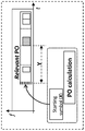
- the UE will perform the PO calculation, and from that, it will obtain the starting location (e.g., in time domain, the starting symbol/slot of the PO) which is also denoted hereafter as X.
- the circuitry of the user device in operation, further receives, from the base station, an indicator of the offset of the paging location for paging the user device with respect to the starting location of the paging region.
- the target location of the paging information e.g. the target paging CORESET
- the indicator of the offset is included in remaining minimum system information, RMSI, or other system information, OSI transmitted by and received from the base station.
- the information indicative (i.e., the indicator) of the offset is a paging bitmap indicative of locations of paging information within the paging region including the paging information for paging said user device.
- the paging bitmap consists of bits each of which corresponds to a resource unit (e.g. resource block, slot) assigned to a location of paging information such as a paging CORESET.
- the respective resource units carry a configuration resource set actually carrying paging information for user devices.
- the paging occasion is a resource unit of a set of resource units configurable by the base station to carry paging information.
- the user device in particular its processing circuitry, further receives, from the base station, a synchronization bitmap indicative of a plurality of locations in which synchronization blocks are transmitted among a set of candidate locations for transmitting synchronization blocks. From the plurality of locations indicated by the synchronization bitmap, the user device then determines an ordinal value of a location of a synchronization block most suitable for synchronization of said user device. Therein, the ordinal value of the synchronization block most suitable for synchronization of said user device corresponding to an ordinal value of the location of the paging information for paging said user device as indicated by the first bitmap.
- the user device determines the location of paging information among the bits set to one of the paging bitmap as corresponding to the ordinal value determined within the synchronization bitmap.
- the user device makes use of the communication system applying beamforming wherein beams pointing into different directions carrying respective synchronization blocks are cyclically switched.
- the determination of the ordinal value of the most suitable synchronization block corresponds to catching the “best beam” among the beams.
- the best beam is the beam from which the user device detects most energy, i.e., the better-detected one.
- a user device will be able to detect energy only from one beam depending of the position of the user device relative to the base station/TRP (unless the user device is located in a boundary area between areas covered by two different beams) .
- the user device knows the ordinal number of the best beam because the different beams associated with the respective ordinal numbers are transmitted during different predetermined time intervals that are known to the user device.
- the user device performs determination of the location of the paging information by counting, from the paging bitmap the bits indicating the time locations where paging information is actually transmitted. For instance, a value “1” represents a candidate location with paging information, and a value “0” represents a candidate location without paging information. If the nth SSB is the SSB associated with the best beam, then the nth bit of the bits indicating actual locations paging information among the candidate locations indicates the location of the paging information for paging the particular user device.
- the paging bitmap is a bitmap over the period of multiple slots/symbols from the slot/symbol X.
- Each bit represents a symbol or slot and depending on its value, the UE knows whether a paging message or paging CORESET is transmitted or not in the respective symbol or slot. In this case the connection with the SSBs would be given by the ordinal of the actually transmitted best SSB of the UE.
- Fig. 7 An example of actually transmitted SSBs among candidate locations is shown in Fig. 7.
- the gNB transmits N SSBs out of the L possibilities.
- slot level indication is assumed.
- UEs can determine the ordinal of the best SSB.
- Figs. 8 and 9 show an example in which the UE is able to detect at t1 the 3 rd SBB and determine the corresponding ordinal (3rd) .
- the UE can, using the ordinal value (3) , determine the symbol/slot (the example assumes slot-level indication) in which the relevant paging message is transmitted, i.e., the slot with the 3 rd ‘1’ in B2.
- the paging bitmap indicates the slot position (offset within the PO) in which the relevant paging CORESET is located.
- the symbol index can be obtained using a formula taking into account, for instance, the corresponding best SSB beam/index.
- the assumption of slot-level indication in Figs. 8 and 9 is merely exemplary. As an alternative example, symbol-level indication is also possible.
- Radio Resource Control (RRC) signaling example in accordance with example 1-1 is shown in Fig. 10. Portions that are newly added in accordance with the present disclosure are indicated by boxes.
- the RRC signalling may be carried in the broadcast system resources such as physical broadcast channel (PBCH) and/or in the RMSI or OSI.
- PBCH physical broadcast channel
- OSI OSI
- information elements common to all paging CORESETs include, CORESET-CCE-REG-mapping-type, CORESET-interleaver-rows, and others.
- an information element CORESET-freq-dom has been added to indicate the frequency resources used to carry the paging CORESET.
- the CORESET-freq-dom thus represents the common PO position in the frequency domain. This may be a particular subcarrier and/or resource block or the like. It is noted that in general, the frequency domain resources does not have to be signalled and may also be prescribed by a standard.
- the RRC signalling example of Figure 10 comprises information related to particular SSBs.
- an information element CORESET-SSB-slot mapping has been added to each CORESET information corresponding to the respective SSBs.
- the CORESET-SSB-slot mapping may be, for instance, bitmap B2 as described above. Accordingly, a terminal (UE) which reads any of the broadcast SSBs obtains the information B2 and based thereon may access the relevant paging information.
- the value indicating the absolute symbol offset with respect to symbol X, or the symbol index in case X represents a slot.
- the calculated starting location indicates a symbol and the indication of the offset is a value indicating the absolute symbol offset with respect to the starting.
- the starting location (starting symbol) of the PO (X) is obtained by means of the PO calculation.
- the value Y representing the offset in terms of symbols with respect to X is indicated.
- the calculated starting location indicates a slot and the indication of the offset is a symbol index within the slot of the starting location.
- the starting slot of the PO (X) is obtained by means of the PO calculation.
- the value Y indicates the symbol index (offset) within the slot denoted by X. It should be noted that in this case, the starting location of the PO refers to a slot, while Y indicates a symbol.
- FIG. 13 An RRC signaling example in accordance with example 1-2 is shown in Fig. 13. Again, portions that are newly added in accordance with the present disclosure are indicated by boxes. Also in this case, common information elements include CORESET-CCE-REG-mapping-type, CORESET-interleaver-rows, etc. In contrast to example 1_1, no element needs to be added to the information common to all SSBs.
- the signalling example of Fig. 13 comprises information relevant to the particular SSBs.
- the element CORESET-freq-dom is signalled in the information directed to the individual SSBs, such as SSB [0] and SSB [1] , in this example.
- another signal element, CORESET-start-symb indicating, for example the frequency offset as an absolute symbol value within a slot, has been added to the signalling sections directed to the individual SSBs.
- the offset with respect to the starting location is a combination indicating the slot offset with respect to symbol X, and the symbol index in the slot. That is, the calculated starting location indicates a symbol and the indication of the offset is a combination of a slot offset with respect to the symbol of the starting location and a symbol index within the slot indicated by the slot offset.
- FIG. 14 An example of alternative 1-3 is shown in Fig. 14.
- the figure shows an exemplary case where the starting location X, obtained by means of the PO calculation, represents an arbitrary symbol.
- the value Y represents a combination indicating the slot offset (with respect to X) and the symbol index/offset within the slot denoting the paging CORESET location. That is, the value to be transmitted Y indicates a combination providing the slot offset (2 in the example) and the symbol index within the targeted slot (slot i in the example) .
- the frequency position for the corresponding SSB can be indicated as an offset.
- Fig. 15 shows an RRC signaling example in corresponding to alternative 1-3, where, again, portions that are newly added in accordance with the present disclosure are indicated by boxes.
- the elements CORESET-CCE-REG-mapping-type, CORESET-interleaver-rows, CORESET-bundle-size etc. common to all Paging CORESETs are signalled in the region which is common for all Paging CORESETS, as can already be seen in Fig. 13.
- CORESET-freq-dom and CORESET-start-symb are signalled in the signalling regions SSB [0] , SSB [1] etc. directed, respectively, to the particular SSBs.
- CORESET-start-slot is signalled for the respective SSBs.
- the two elements CORESET-start-slot and CORESET-start-symbol correspond, respectively, to the values indicating, respectively, the slot offset and the symbol index within the slot. Since a slot is composed of 14 symbols in the time domain, four bits are sufficient to signal the value of CORESET-start-symbol.
- the paging region is specific to the different SSBs transmitted respectively on the different beams, a respective paging region from a plurality of paging regions comprising the paging region including paging information for paging said user device is associated with a respective synchronization block.
- each SSB corresponding to a particular beam has its corresponding paging region.
- the different paging regions corresponding respectively to the different beams/SSBs may be separated from each other by resources (e.g., in the time domain, one or more slots or symbols) not belonging to any paging region.
- resources e.g., in the time domain, one or more slots or symbols
- Embodiment 2 includes an association method to indicate the offset symbol/slot of the paging CORESET in cases where the PO is SSB-specific.
- the association will be based on PO calculation to obtain the staring symbol/slot of the PO and the symbol/slot offset.
- FIG. 16 Another example of separate paging regions (POs) is shown in Fig. 16.
- the POs are specific to the respective SSBs (beams) .
- two variables are required for determining the location of the paging CORESET: the starting symbol/slot of the PO, and the symbol/slot offset with respect to it.
- the circuitry calculates the starting location of the paging region and determines the offset indicating the location of the paging information by performing respective paging occasion, PO, calculations.
- the UE performs the PO calculations, and therefrom, it will obtain 1) the starting symbol/slot of the PO and 2) the corresponding symbol/slot offset with respect to the starting symbol/slot of the PO.
- This behaviour is illustrated in Figure 16.
- both absolute time-location of the PO and relative CORESET position within the PO are SSB-specific and can be obtained from the PO calculation.
- i_s floor (UE_ID/N) mod Ns + SSB_index_number *OffsetBetweenCORESET, with
- SSB_index_number is to count n th SSB index number in TDMed SSBs
- Ns number of Positions/locations
- N min (T, nB) , meaning the minimum (smallest value) one among T and nB.
- nB can be any one of 4T, 2T, T, T/2, T/4, T/8, T/16, T/32, which comes from SIB2 (IE nB) .
- T is DRX cycle of the UE.
- OffsetBetweenCORESET is the symbol distance between two CORESETs.
- each PO position can be obtained directly by the above equation.
- Such a PO calculation corresponds to the PO calculation in as it is done in LTE (using the LTE paging formula specified in TS 36.304, Sec. 7: page 39, incorporated herein by reference) .
- RRC signaling can be performed by the base station as shown in Fig. 17.
- RRC signaling can be performed by the base station as shown in Fig. 17.
- the common signaling to all paging CORESETs is performed with the same elements as in the examples of Figs. 13 and 15, such as CORESET-CCE-REG-mapping-type, CORESET-interleaver-rows, CORESET-bundle-size etc.
- no new elements need added for signaling the location of the paging region, neither in the common signaling to all paging CORESET nor in the SSB-specific signaling. This is because the offset of the CORESET location relative to the starting location is calculated by the user device in a PO calculation rather than being received in the signaling.
- the proposed embodiments provide provide flexibility to signal the location of the target PO under several assumptions, i.e., common PO for different SSBs or SSB-specific PO. Moreover, a UE is not required to monitor all the possible paging-carrying instances (slot or symbols) within the PO.
- the present disclosure can be realized by software, hardware, or software in cooperation with hardware.
- Each functional block used in the description of each embodiment described above can be partly or entirely realized by an LSI such as an integrated circuit, and each process described in the each embodiment may be controlled partly or entirely by the same LSI or a combination of LSIs.
- the LSI may be individually formed as chips, or one chip may be formed so as to include a part or all of the functional blocks.
- the LSI may include a data input and output coupled thereto.
- the LSI here may be referred to as an IC, a system LSI, a super LSI, or an ultra LSI depending on a difference in the degree of integration.
- the technique of implementing an integrated circuit is not limited to the LSI and may be realized by using a dedicated circuit, a general-purpose processor, or a special-purpose processor.
- a FPGA Field Programmable Gate Array
- a reconfigurable processor in which the connections and the settings of circuit cells disposed inside the LSI can be reconfigured may be used.
- the present disclosure can be realized as digital processing or analogue processing. If future integrated circuit technology replaces LSIs as a result of the advancement of semiconductor technology or other derivative technology, the functional blocks could be integrated using the future integrated circuit technology. Biotechnology can also be applied.
- a user device for transmitting and/or receiving data to/from a base station in a communication system.
- the user device comprises circuitry which, in operation, calculates the starting location of a paging region comprising resources in which user devices are paged, the paging region including paging information for paging said user device; and determines an offset with respect to the starting location of the paging region, the offset indicating the location of the paging information for paging said user device relative to the starting location of the paging region.
- the circuitry of the user device in operation, further receives, from a base station, an indication of the offset with respect to the starting location of the paging region; and determines the offset to obtain the location of the paging information for paging said user device based on the information received from the base station.
- the indicator of the offset is a paging bitmap indicative of locations of paging information within the paging region including the paging information for paging said user device.
- the circuitry of the user device further receives, from the base station, a synchronization bitmap indicative of a plurality of locations in which synchronization blocks are transmitted among a set of candidate locations for transmitting synchronization blocks, and determines, from the plurality of locations indicated by the synchronization bitmap, the ordinal value of the location of a synchronization block most suitable for synchronization of said user device.
- the ordinal value of the synchronization block most suitable for synchronization of said user device corresponds to an ordinal value of the location of the paging information for paging said user device as indicated by the first bitmap.
- the calculated starting location indicates a symbol and the indication of the offset is a value indicating the absolute symbol offset with respect to the starting.
- the calculated starting location indicates a slot and the indication of the offset is a symbol index within the slot of the starting location.
- the calculated starting location indicates a symbol and the indication of the offset is a combination of a slot offset with respect to the symbol of the starting location and a symbol index within the slot indicated by the slot offset.
- the indicator of the offset is included in remaining minimum system information, RMSI, or other system information, OSI received from the base station.
- the circuitry of the user device calculates the starting location of the paging region and determines the offset indicating the location of the paging information by performing respective paging occasion, PO, calculations.
- the paging region is a common paging region common for each of a plurality of synchronization blocks.
- a respective paging region from a plurality of paging regions comprising the paging region including paging information for paging said user device is associated with a respective synchronization block.
- the starting location of the paging region and the location of the paging information for paging said user device being locations of resources in the time domain.
- the starting location of the paging region indicates a symbol or a slot.
- the offset indicating the location of the paging information for paging said user device indicates a symbol and/or a slot.
- a base station for transmitting and/or receiving data to/from a user device in a communication system.
- the base station comprises circuitry which, in operation, determines a paging region in which user devices are paged.
- the circuitry further determines an offset with respect to a starting location of the paging region, the offset indicating the location of the paging information for paging said user device relative to a starting location of the paging region.
- the circuitry also allocates the paging information for paging said user device to a resource on the location indicated by the offset.
- the base station also comprises a transmitter which, in operation, transmits the paging information on the resource indicated by the offset to the user device.
- data transmission and/or reception method to be performed by a user device transmitting and/or receiving data to/from a base station in a communication system.
- the method comprises the steps of calculating the starting location of a paging region comprising resources in which user devices are paged, the paging region including paging information for paging said user device and determining an offset with respect to the starting location of the paging region, the offset indicating the location of the paging information for paging said user device relative to the starting location of the paging region.
- a data transmission and/or reception method to be performed by a base station in a communication system.
- the method comprises the steps of determining a paging region in which user devices are paged, determining an offset with respect to a starting location of the paging region, the offset indicating the location of the paging information for paging said user device relative to a starting location of the paging region, allocating the paging information for paging said user device to a resource on the location indicated by the offset, and transmitting the paging information on the resource indicated by the offset to the user device.
- the present invention relates to a user device, a base station, and data transmission and reception methods to be performed by a user device and a base station in a communications system.
- the user device comprises circuitry which, in operation, calculates the starting location of a paging region comprising resources in which user devices are paged, the paging region including paging information for paging said user device; and determines an offset with respect to the starting location of the paging region, the offset indicating the location of the paging information for paging said user device relative to the starting location of the paging region.
Landscapes
- Engineering & Computer Science (AREA)
- Signal Processing (AREA)
- Computer Networks & Wireless Communication (AREA)
- Mobile Radio Communication Systems (AREA)
Priority Applications (12)
| Application Number | Priority Date | Filing Date | Title |
|---|---|---|---|
| CN201780096887.0A CN111357342B (zh) | 2017-11-17 | 2017-11-17 | Nr中ssb到寻呼coreset映射的方案 |
| JP2020522865A JP7002651B2 (ja) | 2017-11-17 | 2017-11-17 | Nrにおけるページングcoresetマッピングに対するssbの機構 |
| CN202211273920.1A CN115955715B (zh) | 2017-11-17 | 2017-11-17 | 用户设备、基站及其执行的数据发送和/或接收方法 |
| PCT/CN2017/111534 WO2019095255A1 (en) | 2017-11-17 | 2017-11-17 | Schemes for ssb to paging coreset mapping in nr |
| EP17931916.5A EP3711396B1 (de) | 2017-11-17 | 2017-11-17 | Schema coreset-mapping von ssb zu funkrufnachrichten in nr |
| US16/874,041 US11445473B2 (en) | 2017-11-17 | 2020-05-14 | Schemes for SSB to paging coreset mapping in NR |
| JP2021212279A JP7328315B2 (ja) | 2017-11-17 | 2021-12-27 | Nrにおけるページングcoresetマッピングに対するssbの機構 |
| US17/874,836 US11711784B2 (en) | 2017-11-17 | 2022-07-27 | Schemes for SSB to paging coreset mapping in NR |
| US18/331,720 US12010652B2 (en) | 2017-11-17 | 2023-06-08 | Schemes for SSB to paging coreset mapping in NR |
| JP2023126941A JP7561245B2 (ja) | 2017-11-17 | 2023-08-03 | Nrにおけるページングcoresetマッピングに対するssbの機構 |
| US18/649,069 US12335917B2 (en) | 2017-11-17 | 2024-04-29 | Schemes for SSB to paging coreset mapping in NR |
| JP2024163926A JP7781238B2 (ja) | 2017-11-17 | 2024-09-20 | Nrにおけるページングcoresetマッピングに対するssbの機構 |
Applications Claiming Priority (1)
| Application Number | Priority Date | Filing Date | Title |
|---|---|---|---|
| PCT/CN2017/111534 WO2019095255A1 (en) | 2017-11-17 | 2017-11-17 | Schemes for ssb to paging coreset mapping in nr |
Related Child Applications (1)
| Application Number | Title | Priority Date | Filing Date |
|---|---|---|---|
| US16/874,041 Continuation US11445473B2 (en) | 2017-11-17 | 2020-05-14 | Schemes for SSB to paging coreset mapping in NR |
Publications (1)
| Publication Number | Publication Date |
|---|---|
| WO2019095255A1 true WO2019095255A1 (en) | 2019-05-23 |
Family
ID=66539276
Family Applications (1)
| Application Number | Title | Priority Date | Filing Date |
|---|---|---|---|
| PCT/CN2017/111534 Ceased WO2019095255A1 (en) | 2017-11-17 | 2017-11-17 | Schemes for ssb to paging coreset mapping in nr |
Country Status (5)
| Country | Link |
|---|---|
| US (4) | US11445473B2 (de) |
| EP (1) | EP3711396B1 (de) |
| JP (4) | JP7002651B2 (de) |
| CN (2) | CN111357342B (de) |
| WO (1) | WO2019095255A1 (de) |
Cited By (5)
| Publication number | Priority date | Publication date | Assignee | Title |
|---|---|---|---|---|
| CN112087795A (zh) * | 2019-06-14 | 2020-12-15 | 华为技术有限公司 | 寻呼方法、设备及存储介质 |
| JP2021517429A (ja) * | 2018-04-02 | 2021-07-15 | ペキン シャオミ モバイル ソフトウェア カンパニー, リミテッドBeijing Xiaomi Mobile Software Co.,Ltd. | 同期ブロードキャスト情報伝送方法及び装置 |
| EP3893568A1 (de) * | 2020-04-09 | 2021-10-13 | Panasonic Intellectual Property Corporation of America | Benutzerausrüstung und basisstation, die an einem funkruf beteiligt sind |
| WO2022006879A1 (zh) * | 2020-07-10 | 2022-01-13 | Oppo广东移动通信有限公司 | 一种寻呼指示的传输方法、电子设备及存储介质 |
| JP2023535571A (ja) * | 2020-07-31 | 2023-08-18 | ホアウェイ・テクノロジーズ・カンパニー・リミテッド | ページング方法及び装置 |
Families Citing this family (12)
| Publication number | Priority date | Publication date | Assignee | Title |
|---|---|---|---|---|
| EP4167619A1 (de) | 2017-02-02 | 2023-04-19 | IPLA Holdings Inc. | Neuer funkruf |
| WO2019134636A1 (en) * | 2018-01-02 | 2019-07-11 | Telefonaktiebolaget Lm Ericsson (Publ) | Method, network device and terminal device for remaining minimum system information |
| CN111699722B (zh) * | 2018-02-09 | 2023-08-25 | Lg电子株式会社 | 在空闲模式下操作的方法和使用该方法的设备 |
| WO2019183791A1 (zh) * | 2018-03-27 | 2019-10-03 | Oppo广东移动通信有限公司 | 同步信号块传输方法、设备及存储介质 |
| WO2021160647A1 (en) * | 2020-02-14 | 2021-08-19 | Telefonaktiebolaget Lm Ericsson (Publ) | ADDITIONAL REFERENCE SIGNALS FOR UEs IN NON-CONNECTED STATES |
| US11963088B2 (en) * | 2020-07-31 | 2024-04-16 | Qualcomm Incorporated | Beam-specific system information inside remaining minimum system information |
| WO2022029039A1 (en) * | 2020-08-05 | 2022-02-10 | Telefonaktiebolaget Lm Ericsson (Publ) | Ssb-aligned transmission of paging-related signals |
| US12114287B2 (en) * | 2020-10-20 | 2024-10-08 | Qualcomm Incorporated | Page indication for idle or inactive state user equipment (UE) |
| WO2022126406A1 (en) * | 2020-12-16 | 2022-06-23 | Qualcomm Incorporated | Adaptive sub-grouping and paging for user equipment |
| WO2023007728A1 (ja) * | 2021-07-30 | 2023-02-02 | 株式会社Nttドコモ | 端末、無線通信方法及び基地局 |
| WO2023015544A1 (en) * | 2021-08-13 | 2023-02-16 | Qualcomm Incorporated | Bandwidth part (bwp) configuration for positioning in an inactive state |
| US12581455B2 (en) * | 2022-08-17 | 2026-03-17 | Qualcomm Incorporated | Reduced beam for paging |
Citations (2)
| Publication number | Priority date | Publication date | Assignee | Title |
|---|---|---|---|---|
| CN105992342A (zh) * | 2015-02-05 | 2016-10-05 | 上海贝尔股份有限公司 | 在基于机器型通信的通信系统中用于接收寻呼消息的方法 |
| WO2017052284A1 (en) * | 2015-09-24 | 2017-03-30 | Lg Electronics Inc. | Method and apparatus for performing a discontinuous reception |
Family Cites Families (14)
| Publication number | Priority date | Publication date | Assignee | Title |
|---|---|---|---|---|
| KR100933160B1 (ko) * | 2006-10-02 | 2009-12-21 | 삼성전자주식회사 | 무선통신 시스템에서의 페이징 정보의 송수신 방법 및 장치 |
| WO2008155739A2 (en) * | 2007-06-19 | 2008-12-24 | Nokia Corporation | Apparatus, method and computer program product providing idle mode discontinuous reception |
| US8295209B2 (en) * | 2008-02-21 | 2012-10-23 | Nokia Corporation | Frame structures with flexible partition boundary for wireless networks |
| KR20100024332A (ko) * | 2008-08-25 | 2010-03-05 | 엘지전자 주식회사 | 페이징 정보 송수신 방법 |
| CN101820650B (zh) * | 2009-02-27 | 2012-11-28 | 中兴通讯股份有限公司 | 一种动态使用Abis时隙资源的方法和系统 |
| US20110310854A1 (en) * | 2010-06-17 | 2011-12-22 | Jialin Zou | Method of determining access times for wireless communication devices |
| US8897818B2 (en) * | 2010-11-11 | 2014-11-25 | Blackberry Limited | System and method for reducing energy consumption of mobile devices using early paging indicator |
| EP4231678B1 (de) * | 2015-02-23 | 2025-09-10 | Panasonic Intellectual Property Corporation of America | Verfahren und funkbasisstation für verbesserte paging-verfahren für benutzervorrichtungen mit reichweitenerweiterungsbedarf |
| US11212760B2 (en) * | 2015-09-24 | 2021-12-28 | Qualcomm Incorporated | Common synchronization channel design for narrowband communications |
| WO2017105305A1 (en) * | 2015-12-16 | 2017-06-22 | Telefonaktiebolaget Lm Ericsson (Publ) | Paging a wireless device |
| CN108886738B (zh) * | 2016-04-04 | 2021-12-03 | 苹果公司 | 用于独立波束成形系统的寻呼设计 |
| EP3473043B1 (de) * | 2016-06-21 | 2021-01-27 | Samsung Electronics Co., Ltd. | System und verfahren zum paging in einem drahtloskommunikationssystem der nächsten generation |
| US10736077B2 (en) * | 2017-05-05 | 2020-08-04 | Qualcomm Incorporated | Configuration of remaining system information transmission window |
| GB2566316A (en) * | 2017-09-11 | 2019-03-13 | Tcl Communication Ltd | Improvements in or relating to paging in new radio |
-
2017
- 2017-11-17 EP EP17931916.5A patent/EP3711396B1/de active Active
- 2017-11-17 CN CN201780096887.0A patent/CN111357342B/zh active Active
- 2017-11-17 WO PCT/CN2017/111534 patent/WO2019095255A1/en not_active Ceased
- 2017-11-17 JP JP2020522865A patent/JP7002651B2/ja active Active
- 2017-11-17 CN CN202211273920.1A patent/CN115955715B/zh active Active
-
2020
- 2020-05-14 US US16/874,041 patent/US11445473B2/en active Active
-
2021
- 2021-12-27 JP JP2021212279A patent/JP7328315B2/ja active Active
-
2022
- 2022-07-27 US US17/874,836 patent/US11711784B2/en active Active
-
2023
- 2023-06-08 US US18/331,720 patent/US12010652B2/en active Active
- 2023-08-03 JP JP2023126941A patent/JP7561245B2/ja active Active
-
2024
- 2024-04-29 US US18/649,069 patent/US12335917B2/en active Active
- 2024-09-20 JP JP2024163926A patent/JP7781238B2/ja active Active
Patent Citations (2)
| Publication number | Priority date | Publication date | Assignee | Title |
|---|---|---|---|---|
| CN105992342A (zh) * | 2015-02-05 | 2016-10-05 | 上海贝尔股份有限公司 | 在基于机器型通信的通信系统中用于接收寻呼消息的方法 |
| WO2017052284A1 (en) * | 2015-09-24 | 2017-03-30 | Lg Electronics Inc. | Method and apparatus for performing a discontinuous reception |
Non-Patent Citations (6)
| Title |
|---|
| DAHLMAN ET AL.: "4G, LTE-Advanced Pro and The Road to 5G", 2016, ELSEVIER |
| ERICSSON: "Paging design", 3GPP TSG RAN WG1 MEETING #90BIS R1-1718714, 9 October 2017 (2017-10-09), Prague, Czech Republic, pages 5, 6, XP051353211 * |
| INTERDIGITAL; INC: "NR paging based on paging indication", 3GPP TSG RAN WG1 MEETING #90BIS R1-1718358, 9 October 2017 (2017-10-09), Prague, CZ, pages 3, 4, XP051352511 * |
| NOKIA ET AL.: "Paging in NR", 3GPP TSG-RAN1 NR AH#3 R1-1716527, 18 October 2017 (2017-10-18), Nagoya, Japan, pages 3 - 5, XP051339980 * |
| NOKIA, R1-1716527, 3GPP TSG-RAN1 NR AH#3, NAGOYA, JAPAN, 18 October 2017 (2017-10-18) |
| PANASONIC: "Discussion on paging design for NR", 3GPP TSG RAN WG1 MEETING #90BIS (R1-1717772), 9 October 2017 (2017-10-09), Prague, CZ, pages 1 - 2, XP051351628 * |
Cited By (12)
| Publication number | Priority date | Publication date | Assignee | Title |
|---|---|---|---|---|
| JP2021517429A (ja) * | 2018-04-02 | 2021-07-15 | ペキン シャオミ モバイル ソフトウェア カンパニー, リミテッドBeijing Xiaomi Mobile Software Co.,Ltd. | 同期ブロードキャスト情報伝送方法及び装置 |
| JP7089051B2 (ja) | 2018-04-02 | 2022-06-21 | ペキン シャオミ モバイル ソフトウェア カンパニー, リミテッド | 同期ブロードキャスト情報伝送方法及び装置 |
| US11617142B2 (en) | 2018-04-02 | 2023-03-28 | Beijing Xiaomi Mobile Software Co., Ltd. | Method and apparatus for transmitting synchronized broadcast transmission |
| US12004103B2 (en) | 2018-04-02 | 2024-06-04 | Beijing Xiaomi Mobile Software Co., Ltd. | Method and apparatus for transmitting synchronized broadcast transmission |
| CN112087795A (zh) * | 2019-06-14 | 2020-12-15 | 华为技术有限公司 | 寻呼方法、设备及存储介质 |
| EP3893568A1 (de) * | 2020-04-09 | 2021-10-13 | Panasonic Intellectual Property Corporation of America | Benutzerausrüstung und basisstation, die an einem funkruf beteiligt sind |
| WO2021204434A1 (en) * | 2020-04-09 | 2021-10-14 | Panasonic Intellectual Property Corporation Of America | User equipment and base station involved in paging |
| JP2023521109A (ja) * | 2020-04-09 | 2023-05-23 | パナソニック インテレクチュアル プロパティ コーポレーション オブ アメリカ | ページングに関与するユーザ機器および基地局 |
| WO2022006879A1 (zh) * | 2020-07-10 | 2022-01-13 | Oppo广东移动通信有限公司 | 一种寻呼指示的传输方法、电子设备及存储介质 |
| JP2023535571A (ja) * | 2020-07-31 | 2023-08-18 | ホアウェイ・テクノロジーズ・カンパニー・リミテッド | ページング方法及び装置 |
| JP7589330B2 (ja) | 2020-07-31 | 2024-11-25 | ホアウェイ・テクノロジーズ・カンパニー・リミテッド | ページング方法及び装置 |
| JP2025028887A (ja) * | 2020-07-31 | 2025-03-05 | ホアウェイ・テクノロジーズ・カンパニー・リミテッド | ページング方法及び装置 |
Also Published As
| Publication number | Publication date |
|---|---|
| US20200275409A1 (en) | 2020-08-27 |
| EP3711396A1 (de) | 2020-09-23 |
| JP2021503205A (ja) | 2021-02-04 |
| CN115955715B (zh) | 2024-11-29 |
| CN111357342B (zh) | 2022-11-04 |
| US11711784B2 (en) | 2023-07-25 |
| JP7561245B2 (ja) | 2024-10-03 |
| US20230319785A1 (en) | 2023-10-05 |
| US11445473B2 (en) | 2022-09-13 |
| CN115955715A (zh) | 2023-04-11 |
| CN111357342A (zh) | 2020-06-30 |
| JP2024175119A (ja) | 2024-12-17 |
| JP7002651B2 (ja) | 2022-01-20 |
| JP7328315B2 (ja) | 2023-08-16 |
| EP3711396A4 (de) | 2021-06-30 |
| JP2022046679A (ja) | 2022-03-23 |
| EP3711396B1 (de) | 2024-07-24 |
| US20240284405A1 (en) | 2024-08-22 |
| US12010652B2 (en) | 2024-06-11 |
| JP2023145701A (ja) | 2023-10-11 |
| US12335917B2 (en) | 2025-06-17 |
| JP7781238B2 (ja) | 2025-12-05 |
| US20220369284A1 (en) | 2022-11-17 |
Similar Documents
| Publication | Publication Date | Title |
|---|---|---|
| US12010652B2 (en) | Schemes for SSB to paging coreset mapping in NR | |
| US12082152B2 (en) | Paging occasion design in new radio | |
| US11350354B2 (en) | Discovery signal transmission/reception method and apparatus for use in mobile communication system | |
| US11582712B2 (en) | Methods and apparatus of timing/frequency tracking for receiving paging | |
| CN110912657B (zh) | 基于共存通信系统的rs的rrm测量和信道估计方法及设备 | |
| US20200305148A1 (en) | Method and apparatus for uplink transmission in multi-carrier systems | |
| US20210051485A1 (en) | Radio resource management (rrm) procedure in a shared spectrum |
Legal Events
| Date | Code | Title | Description |
|---|---|---|---|
| 121 | Ep: the epo has been informed by wipo that ep was designated in this application |
Ref document number: 17931916 Country of ref document: EP Kind code of ref document: A1 |
|
| ENP | Entry into the national phase |
Ref document number: 2020522865 Country of ref document: JP Kind code of ref document: A |
|
| NENP | Non-entry into the national phase |
Ref country code: DE |
|
| ENP | Entry into the national phase |
Ref document number: 2017931916 Country of ref document: EP Effective date: 20200617 |