WO2019097501A1 - Mécanisme de transmission par courroie pour soufflante de tour de refroidissement - Google Patents
Mécanisme de transmission par courroie pour soufflante de tour de refroidissement Download PDFInfo
- Publication number
- WO2019097501A1 WO2019097501A1 PCT/IB2018/059406 IB2018059406W WO2019097501A1 WO 2019097501 A1 WO2019097501 A1 WO 2019097501A1 IB 2018059406 W IB2018059406 W IB 2018059406W WO 2019097501 A1 WO2019097501 A1 WO 2019097501A1
- Authority
- WO
- WIPO (PCT)
- Prior art keywords
- belt
- pulley
- tension
- blower
- cooling tower
- Prior art date
- Legal status (The legal status is an assumption and is not a legal conclusion. Google has not performed a legal analysis and makes no representation as to the accuracy of the status listed.)
- Ceased
Links
Images


Classifications
-
- F—MECHANICAL ENGINEERING; LIGHTING; HEATING; WEAPONS; BLASTING
- F16—ENGINEERING ELEMENTS AND UNITS; GENERAL MEASURES FOR PRODUCING AND MAINTAINING EFFECTIVE FUNCTIONING OF MACHINES OR INSTALLATIONS; THERMAL INSULATION IN GENERAL
- F16H—GEARING
- F16H7/00—Gearings for conveying rotary motion by endless flexible members
- F16H7/02—Gearings for conveying rotary motion by endless flexible members with belts; with V-belts
-
- F—MECHANICAL ENGINEERING; LIGHTING; HEATING; WEAPONS; BLASTING
- F16—ENGINEERING ELEMENTS AND UNITS; GENERAL MEASURES FOR PRODUCING AND MAINTAINING EFFECTIVE FUNCTIONING OF MACHINES OR INSTALLATIONS; THERMAL INSULATION IN GENERAL
- F16H—GEARING
- F16H7/00—Gearings for conveying rotary motion by endless flexible members
- F16H7/08—Means for varying tension of belts, ropes or chains
- F16H7/10—Means for varying tension of belts, ropes or chains by adjusting the axis of a pulley
- F16H7/12—Means for varying tension of belts, ropes or chains by adjusting the axis of a pulley of an idle pulley
-
- F—MECHANICAL ENGINEERING; LIGHTING; HEATING; WEAPONS; BLASTING
- F28—HEAT EXCHANGE IN GENERAL
- F28F—DETAILS OF HEAT-EXCHANGE AND HEAT-TRANSFER APPARATUS, OF GENERAL APPLICATION
- F28F27/00—Control arrangements or safety devices specially adapted for heat-exchange or heat-transfer apparatus
Definitions
- the present invention relates to a cooling tower that cools a circulating heat medium in the liquid phase by heat exchange with air in a heat exchange unit, and more particularly, to a belt transmission mechanism for moving a ventilation fan in the cooling tower with a motor.
- a fan is operated in a heat exchange unit inside the cooling tower. Accordingly, the air (external air) and the heat medium, which are taken in from the outside, are thermally exchanged directly or indirectly to perform cooling.
- a blower used in such a cooling tower usually rotates an impeller by a motor, and conventionally, a driving power transmission mechanism such as a belt transmission mechanism is interposed between the impeller and the motor, and the motor is a blade.
- a driving power transmission mechanism such as a belt transmission mechanism
- the pulley was respectively arrange
- the belt transmission mechanism related to the drive of the blower in the conventional cooling tower is as shown in the patent document, and a V-belt is generally adopted as a belt for transmitting the driving force.
- V-belt When a V-belt is used as such a belt transmission mechanism, the V-belt fits into the V-shaped grooves provided on the outer circumferences of the pulleys on the motor side and the blower side to transmit the driving force.
- the meandering of the belt and the detachment from the pulley were hard to occur.
- the bending rigidity of the belt is large, and accordingly, there is a problem that the loss related to the driving force transmission becomes large.
- the present invention has been made to solve the above problems, and can use a flat belt as a transmission belt for a blower and appropriately arrange a tension adjustment unit that suppresses the meandering of the belt to prevent the belt from falling off. It is an object of the present invention to provide a belt transmission mechanism for a cooling tower fan, which can achieve efficient driving of an impeller while realizing maintenance free.
- the belt transmission mechanism for a cooling tower fan is a cooling tower for causing heat exchange between the air taken in from the outside by the induced draft by the fan and the heat medium to be cooled and the rotational driving force from the motor to the impeller of the fan.
- a drive-side pulley provided integrally with the output shaft of the electric motor
- a driven-side pulley provided integrally with the rotary shaft of the impeller of the blower
- the drive-side pulley A belt which is a flat belt stretched between the driven pulley and the drive pulley and the driven pulley is disposed, and a tension pulley in contact with the belt applies an urging force so that the belt is not bent.
- the tension pulley is arranged to be able to press the belt from the outside of the belt with respect to the part on the belt loosening side with respect to the belt traveling direction in the normal rotation state where induced drafting is performed. It is disposed so as to be located in a region where the distance from the rotation center position is about 35% or less of the distance between the driving pulley and the driven pulley.
- a flat belt is used as a transmission belt which is stretched between the driving pulley and the driven pulley, and the tension pulley in contact with the belt holds the belt so as not to bend.
- the tension adjustment section also has a function of controlling the movement of the belt in the width direction during traveling to suppress the meandering of the belt, and positioning the rotational center position of the tension pulley in a predetermined area near the driven pulley By pushing the looseness side of the belt with the tension pulley, the belt can be properly regulated by the tension pulley of the tension adjustment section, and the impeller of the fan rotates in the opposite direction to the normal operation by external force with the motor stopped.
- the displacement of the belt can be suppressed to prevent falling off each pulley, and the burden of maintenance can be reliably reduced.
- the loss of transmission can be suppressed using a flat belt, and an impeller can be driven efficiently.
- the belt transmission mechanism for a cooling tower fan comprises a supporting device for supporting the electric motor so as to be positionally adjustable to the side of the fan, if necessary.
- the motor is fixed in a predetermined motor supporting state in which the motor output shaft is inclined in advance such that the rotation center axis of the drive side pulley is parallel to the rotation center axis of the driven side pulley by the elastic deformation of
- the support device for supporting the motor in a position adjustable manner is provided, and the direction of the motor output shaft can be adjusted. Inclination is grasped in advance, and by setting the axis inclination angle in the opposite direction by position adjustment using this inclination amount, the inclination of the output shaft generated at the time of fan operation is canceled, and the driving side pulley at the time of fan operation And the driven pulley can be maintained, and an excessive force is not applied to the traveling belt, so that the meandering prevention function of the belt by the tension pulley of the tension adjusting unit can be appropriately exhibited.
- the belt transmission mechanism for a cooling tower fan may include a cover that covers the drive-side pulley, the driven-side pulley, the belt, and the tension adjustment unit, if necessary, And an opening that allows the inside and the outside of the cover to communicate with each other, and at least one or both of the motor output shaft peripheral portion under the drive side pulley and the impeller rotary shaft peripheral portion under the driven side pulley in the cover. At least an opening for allowing external air to flow is formed in the cover.
- the tension adjusting unit may have an arm portion supported so as to be capable of tilting around an axis parallel to the rotation center axis of the driven pulley, as necessary.
- the tension pulley is rotatably attached to the arm portion, and the entire arm portion is urged and inclined in a direction approaching the driven pulley by urging means so as to be in contact with the belt.
- the tension pulley of the tension adjustment unit is attached to the tilting arm, and is biased in a direction to approach the driven pulley by the biasing means, and contacts the belt, thereby tensioning.
- the pulley can be in contact with the belt and push it, and the mechanism for simultaneously suppressing the bending and meandering of the belt can be simplified and compact, and the tension adjustment part located on the air flow path of the fan can be minimized to reduce the air flow resistance.
- FIGS. 1 to 5 a belt transmission mechanism according to an embodiment of the present invention will be described based on FIGS. 1 to 5.
- an example applied to a cooling tower in which two heat exchange units are disposed opposite to each other with a central portion having a fan for induction ventilation as a cross flow type will be described.
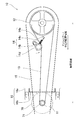
- the belt transmission mechanism 10 is for transmitting the driving force from the motor 70 to the blower 60 of the cooling tower 50, and more specifically, the output shaft of the motor 70 A drive-side pulley 11 disposed integrally with 71, a driven-side pulley 12 integrally disposed with a rotation shaft of an impeller 61 of the blower 60, a drive-side pulley 11 and a driven-side pulley 12
- the belt 13 to be delivered, the tension adjustment unit 14 that holds the belt 13 so as not to bend by the tension pulley 14 d in contact with the belt 13, the drive pulley 11, the driven pulley 12, the belt 13, and the tension adjuster 14
- the cover 15 is provided with a cover 15 and a support device 16 that supports the electric motor 70 on the side of the blower 60 so as to be adjustable in position.
- two heat exchange units are disposed opposite to each other across the central ventilation space as a cross flow type.
- the control system that performs the drive control of 70 is a known configuration, and the detailed description is omitted.
- An electric motor 70 is disposed on the side of the blower 60 in the cooling tower 50 via a support device 16. Then, the rotation of the output shaft 71 of the electric motor 70 is transmitted to the impeller 61 of the blower 60 by the belt transmission mechanism 10, and the impeller 61 rotates to execute induced ventilation.
- the drive-side pulley 11 is fixed to the output shaft 71 of the motor 70 and can be integrally rotated with the output shaft 71.
- the drive-side pulley 11 rotates with the rotation of the output shaft 71 of the motor 70, and is wound.
- the belt 13 that has been hung is caused to travel toward the tension pulley 14 d and the driven pulley 12 of the tension adjustment unit 14.
- the driven pulley 12 is fixed to the rotation shaft of the impeller 61 in the fan 60 and can be integrally rotated with the impeller 61.
- the driven pulley 12 is formed to have an outer diameter larger than that of the driving pulley 11, and is configured to rotate the impeller 61 at a lower rotational speed with respect to the output shaft 71 of the motor 70.
- the belt 13 is formed as an endless flat belt and is stretched between the driving pulley 11 and the driven pulley 12 and travels with the rotation of the driving pulley 11 to cause the driven pulley 12 to rotate. It is
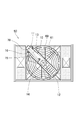
- the tension adjustment unit 14 includes a base portion 14a fixedly installed at a position between the drive-side pulley 11 and the driven-side pulley 12 on the upper side of the blower 60, and rotation of the driven-side pulley 12 at one end of the base portion 14a.
- the arm 14b is attached to be tiltable about an axis parallel to the central axis, and the other end of the base 14a and the tip of the arm 14b are attached at both ends, and the tip of the arm 14b is the other end of the base 14a
- the spring 14c as biasing means for biasing in the direction approaching the part, and the tip of the arm 14b is rotatable around a central axis parallel to the rotational central axis of the driven pulley 12, and the position in the central axial direction is And a tension pulley 14d fitted to the position of the driven pulley 12 and mounted.
- the tension adjusting unit 14 is configured to tension the pulleys 14d with respect to a portion on the belt loosening side in the belt traveling direction in the normal operation state in which the blower 60 performs induced draft, among the portions stretched between the pulleys of the belt 13.
- the distance from the center of rotation of the driven pulley 12 is about 35% or less of the distance between the driving pulley 11 and the driven pulley 12 while the arrangement is such that the pressing of the rotation of the tension pulley 14d is from the center of rotation of the driven pulley 12 It is configured to be located in the area to be positioned, more preferably in the area to be approximately 24 to 31%.
- the base portion 14a of the tension adjusting portion 14 is biased in such a way that the arm portion 14b approaches the driven pulley 12 by the spring 14c and tilts, and the tension pulley 14d on the arm portion 14b presses the belt 13.
- it is configured to be fixed at a predetermined position near the driven pulley 12.
- the arm 14b is tilted in a predetermined direction with respect to the base 14a to move the tension pulley 14d, so that the main part of the tension adjustment unit 14 excluding the tension pulley 14d is
- the compact arrangement can be made on the lower side in a compact manner, and the air flow resistance of the fan 60 resulting from the arrangement of the tension adjustment portion 14 can be minimized.
- the tension pulley 14d contacts the flat belt which is stretched between the pulleys and travels, and prevents meandering of the flat belt and deviation in the belt width direction, for example, Japanese Patent No. 3600833 and Japanese Patent No. 4365713 It has a known meandering prevention mechanism as described in U.S. Pat.
- Such a tension pulley 14d is urged in a direction approaching the driven pulley 12 together with the arm portion 14b and is inclined to contact the belt 13 to apply a tension, thereby bending the belt 13 into a stretched state. While being held so as not to be bent, the movement in the width direction of the belt 13 can be controlled to suppress meandering and the like.
- the traveling direction of the belt 13 is temporarily reverse to the normal operating state of the blower 60. Even when the direction is changed, the meandering prevention function of the tension pulley 14d with respect to the belt 13 can be maintained, and the shift of the belt 13 can be suppressed to prevent the belt 13 from falling off each pulley.
- the blower of the cooling tower is reverse to the normal operation by the motor drive by the wind pressure applied to the impeller due to the flow of the outside air during strong wind or the like and the exhaust from other cooling towers closely arranged when the motor stops. It has the feature that the impeller can rotate in the direction.
- a tension belt having a flat belt and a meandering prevention mechanism corresponding thereto is temporarily provided near the drive-side pulley of the motor output shaft, similarly to a general blower in which reverse rotation of the impeller can not occur.
- the impeller rotates in the opposite direction to that in the normal operation, the relationship between the force applied to the belt from the tension pulley and the traveling direction of the belt changes
- the cover 15 is formed in a substantially box shape and disposed on the upper side of the blower 60 and covers the drive pulley 11, the driven pulley 12, the belt 13, and the tension adjustment unit 14.
- the cover 15 prevents water from going to the blower 60 from the outside such as rain, or water droplets contained in the air reaching the blower 60 from inside the cooling tower by induced draft reaching the respective parts of the transmission mechanism and giving an adverse effect.
- the tension adjustment portion peripheral portion of the cover 15 has no opening for communicating the inside and the outside of the cover. At the time when the cover 15 is provided, if there is a gap serving as an opening between the cover and another member adjacent to the tension adjustment portion 14, no elastic material or the like is inserted or filled. . By eliminating the opening around the tension adjusting unit 14, deterioration of the tension adjusting unit 14 is prevented by preventing water and damp air from inside the cooling tower from coming into contact with the tension adjusting unit 14.
- water is allowed to pass from the inside of the cover to at least one or both of the motor output shaft peripheral portion on the lower side of the drive side pulley 11 in the cover 15 and the impeller rotational axis side portion on the lower side of the driven side pulley 12 Make the opening exist.
- these portions of the cover 15 have at least through holes of a size that allows them to pass through
- the opening is provided from the beginning, and the opening can be formed as a part of such a through hole, that is, as a gap portion left without being blocked by a member such as a shaft passed through the through hole.
- the present invention is not limited to this, and through holes serving as openings may be separately formed in the motor output shaft peripheral portion of the cover 15 or the impeller rotary shaft peripheral portion.
- the openings around the motor output shaft of the cover 15 and around the impeller rotation shaft are directed downward and out of the flow path of the air blown by the blower 60. There is no risk of water from entering the cover.
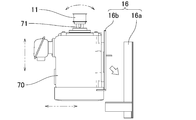
- the support device 16 supports the motor 70 on the side of the blower 60 so as to be adjustable in position.
- the support device 16 includes a base 16a integrated with the blower 60, and an adjustment frame 16b attached to the base 16a so that the position and the direction with respect to the base 16a can be finely adjusted and the motor 70 is fixed. It is the composition provided.
- the rotation center axis of the drive side pulley 11 becomes the rotation center axis of the driven side pulley 12
- the support state of the motor 70 that is parallel is obtained by adjusting the position of the adjustment frame portion 16b with respect to the base portion 16a.
- a plurality of combinations of the size of the blower and the output of the motor for driving the blower are set in accordance with the required performance.
- the movement of the motor 70 on the support device 16 is fixed with the output shaft 71 in parallel with the fan rotation shaft.
- the inclination degree of the output shaft 71 when each part of the blower is elastically deformed by applying a force corresponding to a load is available as adjustment data.
- the position adjustment of the motor 70 using the support device 16 makes the known direction of the motor output shaft 71 on the opposite side to the side inclined when the fan is operated. To obtain a predetermined motor support state which is inclined by a predetermined angle corresponding to (see FIG. 5).
- the rotation center axis of the drive side pulley 11 becomes parallel to the rotation center axis of the driven side pulley 12, and the position in the center axis direction of the drive side pulley 11 is the position in the center axis direction of the driven side pulley 12
- the motor 70 can be fixed such that the direction of the belts stretched around these two pulleys is perpendicular to the central axis direction of each pulley.
- the blower is commissioned at each installation site of the cooling tower to grasp the positional deviation between the pulleys due to the deformation of each part of the blower in the operating state. Then, based on that, it is possible to save time and effort of finely adjusting the position of the motor and setting the positional relationship of each pulley to an appropriate state.
- a heat medium to be cooled such as circulating water that has absorbed heat and is warmed by a refrigerator or an air conditioner, is taken out from a predetermined circulation path and is used as a cooling tower.
- the process of flowing inside the 50 heat exchange sections and returning to the circulation path again after the heat exchange is repeated.
- external air is introduced to the heat exchange unit by induced draft by the blower 60, and the heat medium is cooled by heat exchange with air in the heat exchange unit, and the air after heat exchange cools the blower 60 from the heat exchange unit. Then, it is exhausted above the cooling tower 50.
- the motor 70 operates under predetermined control such as ON / OFF according to the load condition (circulating water temperature, circulating water amount, etc.), and the driving pulley 11 rotates integrally with the output shaft 71 of the motor 70. Do. As the drive pulley 11 rotates, the belt 13 wound around the drive pulley 11 and passed between the drive pulley 11 and the driven pulley 12 travels toward the driven pulley 12. , And the driven pulley 12 is rotated.
- the load condition circulating water temperature, circulating water amount, etc.
- the traveling belt 13 is in contact with the tension pulley 14 d of the tension adjustment unit 14 immediately before reaching the driven pulley 12 and is pushed by the tension pulley 14 d biased by the spring 14 c and pushed by the tension pulley 14 d. It is overstretched and is in a proper tension state.
- the tension pulley 14d exhibits a known meandering prevention function for preventing meandering of the belt 13 and deviation in the belt width direction in contact with the traveling belt 13, and the belt 13 has a width direction By controlling the movement, it is possible to suppress meandering and detachment from each pulley.
- the driven pulley 12 which rotates by obtaining driving force by the belt 13 which continues the traveling state rotates the integral impeller 61 in the same rotation direction.
- the rotation of the driven pulley 12 and the impeller 61 is decelerated at a reduction ratio determined from the outer diameter of the driving pulley 11 and the outer diameter of the driven pulley 12 with respect to the rotation of the motor output shaft 71.
- the driving pulley 11 and the belt 13, and the belt 13 and the driven pulley 12 are always in contact with each other, and the mutual friction causes the driving force to be transmitted to generate noise during the operation of the blower.
- the belt 13 is a flat belt, is excellent in flexibility, and can make noise smaller than in the case of transmission by a V-belt or the like.
- the flat belt it is thin, and the influence of distortion due to bending is small, and it is excellent in durability, and bending resistance can be suppressed, transmission efficiency can be enhanced, and energy consumption related to driving of the fan can be reduced.
- control is performed to temporarily stop the air blowing by the blower, that is, to stop the motor to operate the blower according to the load and the conditions of the surrounding environment, thus stopping the motor.
- the impeller may rotate in the opposite direction to that in the normal operation by the motor drive due to the wind pressure applied to the impeller due to the strong wind and the exhaust from the adjacent cooling tower.
- the belt 13 wound around the driven pulley 12, which rotates integrally with the impeller 61 also travels in the opposite direction to the normal operation of the impeller 61.
- the tension pulleys 14d of the belt 13 By arranging the tension pulleys 14d of the belt 13 closer to the driven pulley 12, the mutual relationship between the belt 13 and the tension pulleys 14d can be hardly changed even if the running direction of the belt 13 is reversed, The meandering prevention function of the pulley 14d can be maintained as it is, and the meandering of the belt 13 and the falling off from each pulley can be prevented.
- a flat belt is used as the transmission belt 13 stretched between the driving pulley 11 and the driven pulley 12, and the slack side of the belt 13 is used.
- the tension adjustment section 14 which holds the belt 13 so as not to bend by the tension pulley 14d in contact with it has a function of controlling the movement of the belt 13 in the width direction during traveling to suppress the meandering of the belt 13 By positioning the rotation center position of the pulley 14d in a predetermined area near the driven pulley 12, the belt 13 can be appropriately regulated by the tension pulley 14d of the tension adjusting unit 14, and the impeller of the blower 60 is subjected to external force when the motor is stopped.
- the cooling tower to which the belt transmission mechanism is applied has a cross flow configuration, but the invention is not limited thereto, and a blower may be disposed in the upper portion of the cooling tower.
- a blower may be disposed in the upper portion of the cooling tower.
- it can be applied to other types of cooling towers such as a countercurrent type.
- the tension adjustment unit 14 tilts the arm portion 14b with respect to the fixed base portion 14a to press the tension pulley 14d attached to the arm portion 14b against the belt 13.
- the tension adjustment unit may move the tension pulley in a motion other than tilting the tension pulley, such as a tension pulley that linearly moves to push the belt in a certain direction and apply tension to the belt. It does not matter as a structure made to contact.
Landscapes
- Engineering & Computer Science (AREA)
- General Engineering & Computer Science (AREA)
- Mechanical Engineering (AREA)
- Physics & Mathematics (AREA)
- Thermal Sciences (AREA)
- Structures Of Non-Positive Displacement Pumps (AREA)
- Devices For Conveying Motion By Means Of Endless Flexible Members (AREA)
Abstract
L'invention concerne un mécanisme de transmission par courroie pour une soufflante de tour de refroidissement, lequel mécanisme utilise une courroie plate comme courroie de transmission pour une soufflante, et lequel a une partie d'ajustement de tension positionnée de façon appropriée qui maintient la courroie alignée, de façon à empêcher ainsi la courroie de tomber et à rendre ainsi la courroie exempte d'entretien, tout en améliorant l'efficacité de l'entraînement d'une hélice. De façon spécifique, la courroie plate est utilisée à titre de courroie de transmission (13), celle-ci s'étendant entre une poulie côté entraînement (11) et une poulie côté entraîné (12). Une partie d'ajustement de tension (14), qui maintient la courroie (13) à l'aide d'une poulie de tension (14d) qui est en contact avec la courroie (13) de telle sorte que la courroie (13) ne s'infléchit pas, est conçue de façon à avoir pour fonction de maintenir la courroie (13) alignée pendant le déplacement. En outre, du fait que la position de centre de rotation de la poulie de tension (14d) est disposée à proximité de la poulie côté entraîné (12), la courroie (13) peut être commandée de manière appropriée par la poulie de tension (14d) de la partie d'ajustement de tension (14), et, par l'élimination d'un défaut d'alignement de la courroie (13), même si la direction de déplacement de la courroie (13) est altérée par la rotation en sens inverse de l'hélice (13), la courroie (13) peut être empêchée de tomber hors des poulies.
Applications Claiming Priority (2)
| Application Number | Priority Date | Filing Date | Title |
|---|---|---|---|
| JP2017222851A JP2019094940A (ja) | 2017-11-20 | 2017-11-20 | 冷却塔送風機用ベルト伝動機構 |
| JP2017-222851 | 2017-11-20 |
Publications (1)
| Publication Number | Publication Date |
|---|---|
| WO2019097501A1 true WO2019097501A1 (fr) | 2019-05-23 |
Family
ID=66538986
Family Applications (1)
| Application Number | Title | Priority Date | Filing Date |
|---|---|---|---|
| PCT/IB2018/059406 Ceased WO2019097501A1 (fr) | 2017-11-20 | 2018-11-28 | Mécanisme de transmission par courroie pour soufflante de tour de refroidissement |
Country Status (3)
| Country | Link |
|---|---|
| JP (1) | JP2019094940A (fr) |
| TW (2) | TWM577458U (fr) |
| WO (1) | WO2019097501A1 (fr) |
Cited By (1)
| Publication number | Priority date | Publication date | Assignee | Title |
|---|---|---|---|---|
| CN112404585A (zh) * | 2020-11-09 | 2021-02-26 | 马鞍山海森控电气有限公司 | 浮动轮涨紧机构 |
Families Citing this family (1)
| Publication number | Priority date | Publication date | Assignee | Title |
|---|---|---|---|---|
| JP7536233B2 (ja) * | 2020-04-01 | 2024-08-20 | 空研工業株式会社 | 冷却塔送風機用ベルト伝動機構 |
Citations (6)
| Publication number | Priority date | Publication date | Assignee | Title |
|---|---|---|---|---|
| JPS5693552U (fr) * | 1979-12-19 | 1981-07-25 | ||
| JPS615229U (ja) * | 1984-06-18 | 1986-01-13 | 三菱自動車工業株式会社 | 作業車両の動力取出装置 |
| JP2003097655A (ja) * | 2001-09-25 | 2003-04-03 | Daihatsu Motor Co Ltd | 無段変速機 |
| JP2005030422A (ja) * | 2003-07-07 | 2005-02-03 | Fuji Photo Film Co Ltd | 帯材の送出装置 |
| JP2015135233A (ja) * | 2008-03-24 | 2015-07-27 | プライム デイタム、インコーポレーテッド | 空冷式熱交換器の一体型ファン駆動システム |
| JP2017122470A (ja) * | 2016-01-06 | 2017-07-13 | バンドー化学株式会社 | オートテンショナ |
-
2017
- 2017-11-20 JP JP2017222851A patent/JP2019094940A/ja active Pending
-
2018
- 2018-11-19 TW TW107215677U patent/TWM577458U/zh unknown
- 2018-11-19 TW TW107141040A patent/TW201923256A/zh unknown
- 2018-11-28 WO PCT/IB2018/059406 patent/WO2019097501A1/fr not_active Ceased
Patent Citations (6)
| Publication number | Priority date | Publication date | Assignee | Title |
|---|---|---|---|---|
| JPS5693552U (fr) * | 1979-12-19 | 1981-07-25 | ||
| JPS615229U (ja) * | 1984-06-18 | 1986-01-13 | 三菱自動車工業株式会社 | 作業車両の動力取出装置 |
| JP2003097655A (ja) * | 2001-09-25 | 2003-04-03 | Daihatsu Motor Co Ltd | 無段変速機 |
| JP2005030422A (ja) * | 2003-07-07 | 2005-02-03 | Fuji Photo Film Co Ltd | 帯材の送出装置 |
| JP2015135233A (ja) * | 2008-03-24 | 2015-07-27 | プライム デイタム、インコーポレーテッド | 空冷式熱交換器の一体型ファン駆動システム |
| JP2017122470A (ja) * | 2016-01-06 | 2017-07-13 | バンドー化学株式会社 | オートテンショナ |
Cited By (1)
| Publication number | Priority date | Publication date | Assignee | Title |
|---|---|---|---|---|
| CN112404585A (zh) * | 2020-11-09 | 2021-02-26 | 马鞍山海森控电气有限公司 | 浮动轮涨紧机构 |
Also Published As
| Publication number | Publication date |
|---|---|
| TWM577458U (zh) | 2019-05-01 |
| TW201923256A (zh) | 2019-06-16 |
| JP2019094940A (ja) | 2019-06-20 |
Similar Documents
| Publication | Publication Date | Title |
|---|---|---|
| CN209621975U (zh) | 冷却塔送风机用带传动机构 | |
| WO2019097501A1 (fr) | Mécanisme de transmission par courroie pour soufflante de tour de refroidissement | |
| US4339991A (en) | Wind control apparatus for air conditioner | |
| US4407077A (en) | Belt drive system | |
| CN101446289B (zh) | 空气压缩机 | |
| KR101871944B1 (ko) | 베인 장치 | |
| CN111121174B (zh) | 风机组件、窗机空调及其控制方法 | |
| JP7536233B2 (ja) | 冷却塔送風機用ベルト伝動機構 | |
| US6021955A (en) | Method and apparatus for controlling the speed of a damper blade | |
| JP5043382B2 (ja) | 冷却塔用送風機 | |
| CN110145798B (zh) | 空调室内机以及具有其的空调器 | |
| KR100651793B1 (ko) | 체인장력조절기구 | |
| KR100751574B1 (ko) | 팬벨트 자동조절기 부착형 공기조화기 | |
| KR102167749B1 (ko) | 바람에 의해 자동 제어되는 팬장치 및 그를 포함하는 냉각장치 | |
| JP2000198340A (ja) | 車両用空調装置 | |
| JP7465749B2 (ja) | 平ベルト伝動システム | |
| KR200145271Y1 (ko) | 차량용 리어쿨링 장치 | |
| JP2020050158A (ja) | 車両のフロントグリル装置 | |
| JP2007132608A (ja) | 空気調和機 | |
| DK167600B1 (da) | Dekantercentrifuge | |
| JP2013087980A (ja) | 空気調和機 | |
| JP2004316435A (ja) | 多翼型送風装置 | |
| KR19990032949U (ko) | 기울기 가변형 블래이드를 가지는 블로워팬 | |
| KR20030022991A (ko) | 소둔로용 구동체인 장력 조절장치 | |
| KR20050064187A (ko) | 공기조화기용 송풍기의 벨트 장력조절수단 |
Legal Events
| Date | Code | Title | Description |
|---|---|---|---|
| 121 | Ep: the epo has been informed by wipo that ep was designated in this application |
Ref document number: 18879779 Country of ref document: EP Kind code of ref document: A1 |
|
| 122 | Ep: pct application non-entry in european phase |
Ref document number: 18879779 Country of ref document: EP Kind code of ref document: A1 |