WO2019097577A1 - 計測システム、補正処理装置、補正処理方法、及びコンピュータ読み取り可能な記録媒体 - Google Patents
計測システム、補正処理装置、補正処理方法、及びコンピュータ読み取り可能な記録媒体 Download PDFInfo
- Publication number
- WO2019097577A1 WO2019097577A1 PCT/JP2017/040945 JP2017040945W WO2019097577A1 WO 2019097577 A1 WO2019097577 A1 WO 2019097577A1 JP 2017040945 W JP2017040945 W JP 2017040945W WO 2019097577 A1 WO2019097577 A1 WO 2019097577A1
- Authority
- WO
- WIPO (PCT)
- Prior art keywords
- vibration
- measuring
- measurement
- displacement
- measurement device
- Prior art date
- Legal status (The legal status is an assumption and is not a legal conclusion. Google has not performed a legal analysis and makes no representation as to the accuracy of the status listed.)
- Ceased
Links
Images




Classifications
-
- G—PHYSICS
- G01—MEASURING; TESTING
- G01H—MEASUREMENT OF MECHANICAL VIBRATIONS OR ULTRASONIC, SONIC OR INFRASONIC WAVES
- G01H17/00—Measuring mechanical vibrations or ultrasonic, sonic or infrasonic waves, not provided for in the other groups of this subclass
-
- G—PHYSICS
- G01—MEASURING; TESTING
- G01B—MEASURING LENGTH, THICKNESS OR SIMILAR LINEAR DIMENSIONS; MEASURING ANGLES; MEASURING AREAS; MEASURING IRREGULARITIES OF SURFACES OR CONTOURS
- G01B11/00—Measuring arrangements characterised by the use of optical techniques
-
- G—PHYSICS
- G01—MEASURING; TESTING
- G01M—TESTING STATIC OR DYNAMIC BALANCE OF MACHINES OR STRUCTURES; TESTING OF STRUCTURES OR APPARATUS, NOT OTHERWISE PROVIDED FOR
- G01M99/00—Subject matter not provided for in other groups of this subclass
-
- G—PHYSICS
- G06—COMPUTING OR CALCULATING; COUNTING
- G06T—IMAGE DATA PROCESSING OR GENERATION, IN GENERAL
- G06T7/00—Image analysis
- G06T7/0002—Inspection of images, e.g. flaw detection
-
- G—PHYSICS
- G06—COMPUTING OR CALCULATING; COUNTING
- G06T—IMAGE DATA PROCESSING OR GENERATION, IN GENERAL
- G06T7/00—Image analysis
- G06T7/20—Analysis of motion
- G06T7/223—Analysis of motion using block-matching
-
- G—PHYSICS
- G06—COMPUTING OR CALCULATING; COUNTING
- G06T—IMAGE DATA PROCESSING OR GENERATION, IN GENERAL
- G06T7/00—Image analysis
- G06T7/20—Analysis of motion
- G06T7/246—Analysis of motion using feature-based methods, e.g. the tracking of corners or segments
- G06T7/248—Analysis of motion using feature-based methods, e.g. the tracking of corners or segments involving reference images or patches
-
- G—PHYSICS
- G06—COMPUTING OR CALCULATING; COUNTING
- G06T—IMAGE DATA PROCESSING OR GENERATION, IN GENERAL
- G06T7/00—Image analysis
- G06T7/20—Analysis of motion
- G06T7/292—Multi-camera tracking
-
- G—PHYSICS
- G06—COMPUTING OR CALCULATING; COUNTING
- G06T—IMAGE DATA PROCESSING OR GENERATION, IN GENERAL
- G06T7/00—Image analysis
- G06T7/97—Determining parameters from multiple pictures
-
- G—PHYSICS
- G01—MEASURING; TESTING
- G01H—MEASUREMENT OF MECHANICAL VIBRATIONS OR ULTRASONIC, SONIC OR INFRASONIC WAVES
- G01H9/00—Measuring mechanical vibrations or ultrasonic, sonic or infrasonic waves by using radiation-sensitive means, e.g. optical means
-
- G—PHYSICS
- G06—COMPUTING OR CALCULATING; COUNTING
- G06T—IMAGE DATA PROCESSING OR GENERATION, IN GENERAL
- G06T2207/00—Indexing scheme for image analysis or image enhancement
- G06T2207/30—Subject of image; Context of image processing
- G06T2207/30108—Industrial image inspection
- G06T2207/30132—Masonry; Concrete
-
- G—PHYSICS
- G06—COMPUTING OR CALCULATING; COUNTING
- G06T—IMAGE DATA PROCESSING OR GENERATION, IN GENERAL
- G06T2207/00—Indexing scheme for image analysis or image enhancement
- G06T2207/30—Subject of image; Context of image processing
- G06T2207/30181—Earth observation
- G06T2207/30184—Infrastructure
-
- G—PHYSICS
- G06—COMPUTING OR CALCULATING; COUNTING
- G06T—IMAGE DATA PROCESSING OR GENERATION, IN GENERAL
- G06T2207/00—Indexing scheme for image analysis or image enhancement
- G06T2207/30—Subject of image; Context of image processing
- G06T2207/30244—Camera pose
Definitions
- the present invention relates to a measurement system, a correction processing apparatus and a correction processing method used therefor, and further relates to a computer readable recording medium recording a program for realizing them.
- Patent Document 1 discloses a vibration measurement device using an imaging device.
- the vibration measurement device disclosed in Patent Document 1 acquires a time-series image of an object from an imaging device, performs image processing on the acquired time-series image, and measures the vibration of the object.
- the vibration measurement device disclosed in Patent Document 1 can measure only the vibration component in the two-dimensional direction in the image, and can not measure the vibration component in the optical axis direction of the imaging device.
- Patent Document 2 discloses a vibration measuring apparatus using a distance measuring device such as a laser distance meter and an ultrasonic distance meter in addition to an imaging device. According to the vibration measurement device disclosed in Patent Document 2, not only the vibration component in the two-dimensional direction in the image but also the vibration component in the optical axis direction of the imaging device can be measured by the distance measurement device. The vibration of the object can be measured in
- the vibration measurement device may be vibrated by itself because the vibration measurement device is installed in a location susceptible to vibration due to the structure of the infrastructure structure.
- the vibration measuring device may be installed on the inspection path of the bridge or a structural member of the bridge, and in this case, when the vehicle passes and the bridge shakes, the vibration measuring device It also vibrates itself.
- the vibration measuring device itself vibrates, its own vibration is superimposed on the vibration of the object and observed, so that it becomes difficult to accurately measure only the vibration component of the object.
- One example of the object of the present invention is a measurement system that can accurately measure the vibration of an object even if the installation location of the measurement device that measures the vibration of the object is free from the above problems.
- An object of the present invention is to provide a correction processing device, a correction processing method, and a computer readable recording medium.
- a measurement system is A measurement device for measuring the vibration of an object, an imaging device arranged to photograph the measurement device, and a correction processing device;
- the correction processing device is A displacement calculation unit that calculates displacement of the measurement device from a time-series image of the measurement device output from the imaging device;
- a movement amount calculation unit configured to calculate the movement amount of the measurement device with respect to the imaging device based on the displacement;
- a correction processing unit that corrects the vibration of the object measured by the measurement device using the calculated movement amount of the measurement device; Equipped with It is characterized by
- the correction processing device is a device for correcting vibration measured by a measuring device that measures vibration of an object, A displacement calculation unit that calculates displacement of the measurement device from a time-series image of the measurement device output from an imaging device arranged to photograph the measurement device; A movement amount calculation unit configured to calculate the movement amount of the measurement device with respect to the imaging device based on the displacement; A correction processing unit that corrects the vibration of the object measured by the measurement device using the calculated movement amount of the measurement device; Equipped with It is characterized by
- the correction processing method is a method for correcting the vibration measured by a measuring device that measures the vibration of the object, (A) calculating a displacement of the measurement device from a time-series image of the measurement device output from an imaging device arranged to photograph the measurement device; (B) calculating, based on the displacement, a movement amount of the measurement device with reference to the imaging device; (B) correcting the vibration of the object measured by the measurement device using the calculated movement amount of the measurement device; Have It is characterized by
- a computer readable recording medium is a computer reading program for correcting a vibration measured by a measuring device for measuring a vibration of an object by a computer.
- Possible recording media On the computer (A) calculating a displacement of the measurement device from a time-series image of the measurement device output from an imaging device arranged to photograph the measurement device; (B) calculating, based on the displacement, a movement amount of the measurement device with reference to the imaging device; (C) correcting the vibration of the object measured by the measurement device using the calculated movement amount of the measurement device; And recording a program including an instruction to execute the program.
- the present invention it is possible to accurately measure the vibration of the object even if the installation location of the measurement device that measures the vibration of the object is a place that is susceptible to the vibration.
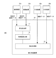
- FIG. 1 is a configuration diagram showing a schematic configuration of a measurement system and a correction processing device according to an embodiment of the present invention.
- FIG. 2 is a block diagram more specifically showing the entire configuration of the measurement system according to the embodiment of the present invention.
- FIG. 3 is a block diagram more specifically showing the configuration of the correction processing apparatus according to the embodiment of the present invention.
- FIG. 4 is a view for explaining the case where the measurement system according to the embodiment of the present invention is used for vibration measurement of a bridge.
- FIG. 5 is a flowchart showing the operation of the correction processing apparatus according to the embodiment of the present invention.
- FIG. 6 is a block diagram showing a modification 1 of the measurement system in the embodiment of the present invention.
- FIG. 7 is a block diagram showing a modification 2 of the measurement system in the embodiment of the present invention.
- FIG. 8 is a block diagram showing an example of a computer that implements the correction processing device according to the embodiment of the present invention.
- FIG. 1 is a configuration diagram showing a schematic configuration of a measurement system and a correction processing device according to an embodiment of the present invention.
- Measurement system 100 in the present embodiment shown in FIG. 1 is a system for measuring the vibration of object 40.
- examples of the object 40 include infrastructure structures such as bridges, roads, buildings, and facilities.
- the measurement system 100 includes a measurement device 20, an imaging device 30, and a correction processing device 10.
- the measuring device 20 is a device that measures the vibration of the object 40.
- the imaging device 30 is arranged to photograph the measuring device 20.
- the correction processing device 10 includes a displacement calculation unit 11, a movement amount calculation unit 12, and a correction processing unit 13.
- the displacement calculating unit 11 calculates the displacement of the measuring device 20 from the time-series image of the measuring device 20 output from the imaging device 30.
- the movement amount calculation unit 12 calculates the movement amount of the measuring device 20 based on the imaging device 30 based on the calculated displacement of the measuring device 20.
- the correction processing unit 13 corrects the vibration of the target object 40 measured by the measuring device 20 using the calculated movement amount of the measuring device 20.
- the amount of movement of the measuring device 20 generated by the vibration of the object 40 that is, the amount of vibration of the measuring device 20 itself is calculated. Then, the amount of vibration of the measuring device 20 itself is canceled from the vibration measured by the measuring device 20 by the correction. For this reason, according to the present embodiment, even if the installation place of the measuring device 20 for measuring the vibration of the object 40 is a place where the vibration is easily received, the vibration of the object 40 can be measured accurately.
- FIG. 2 is a block diagram more specifically showing the entire configuration of the measurement system according to the embodiment of the present invention.
- FIG. 3 is a block diagram more specifically showing the configuration of the correction processing apparatus according to the embodiment of the present invention.
- FIG. 4 is a view for explaining the case where the measurement system according to the embodiment of the present invention is used for vibration measurement of a bridge.
- the measurement system 100 includes a plurality of measurement devices and imaging devices.
- the measurement system 100 includes measurement devices 20 a and 20 b and imaging devices 30 a and 30 b.
- measurement device 20 when one of the measurement devices is not distinguished, it is simply described as “measurement device 20”, and when one of the imaging devices is not distinguished, it is simply described as “imaging device 30”.
- the target object 40 is a bridge
- the measuring devices 20a and 20b have a superstructure of the bridge, for example, a predetermined area of the lower surface such as a girder or floor slab (hereinafter referred to as "measurement target area" Vibration) is measured.
- each of the measuring devices 20a and 20b is arranged to be able to measure the vibration at different parts of the object 40 at a distance from each other.
- the directions of vibration measured by the measuring devices 20a and 20b are three directions of two orthogonal directions on the measurement target area and a direction (normal direction) perpendicular to the measurement target area. It is set in the direction.
- the measuring devices 20a and 20b measure the vibration in three directions, an imaging device (different from the imaging device 30) that images the measurement target region and a distance meter that measures the distance from the measurement device to the measurement target region And have. Then, the measuring devices 20a and 20b measure the vibration in two orthogonal directions on the measurement target region from the image output from the image pickup device of the own device, and from the distance measured by the distance meter, the normal direction of the measurement target region Measure the vibration in
- the measuring devices 20 a and 20 b also input vibration data specifying the measured vibration in three directions to the correction processing device 10.
- the configurations of the measuring devices 20a and 20b are not limited to the configuration shown in FIG.
- the measuring devices 20a and 20b may be configured only by an imaging device (different from the imaging device 30). In this case, the measuring devices 20a and 20b specify the vibration in three directions from the image captured by the imaging device included in each.
- the imaging device 30 a corresponds to the measuring device 20 a, and is fixed to the corresponding measuring device 20 b so as to be able to image another measuring device 20 a.
- the imaging device 30b corresponds to the measuring device 20b, and is fixed to the corresponding measuring device 20b so as to capture another measuring device 20a.
- the displacement calculation unit 11 of each of the imaging devices 30 in the correction processing device 10 can measure The displacement of the measuring device 20 is calculated from the time-series image.
- the movement amount calculation unit 12 calculates, for each of the measuring devices 20, the movement amount of each of the measuring devices 20 based on the imaging device 30 that has captured it based on the displacement calculated for each of the measuring devices 20.
- the correction processing unit 13 corrects the vibration of the target object 40 measured by the measuring device 20 using the calculated movement amount of each measuring device 20 for each measuring device 20.
- the displacement calculation unit 11 obtains, for each imaging device 30, a time-series image to be output, sets an image captured at an arbitrary time as a reference image, and the other as a processed image. Do. Then, the displacement calculation unit 11 calculates displacement for at least one or more specific regions (hereinafter referred to as “specific region”) on the reference image for each processed image.
- the displacement calculation unit 11 first compares the specific area on the processed image with the specific area on the reference image to determine the position of the area most similar to the specific area of the reference image in the processed image. To calculate the displacement (d1x, d1y) of the specific area.
- SAD Sum of Squared Difference
- SSD Sum of Absolute Difference
- NCC Normalized Cross-Correlation
- ZNCC Zero-means Normalized Cross-Correlation
- the similarity correlation function of the area at the position (coordinates) with the highest correlation and the position (coordinates) before and after the position (coordinates) is used to calculate this.
- the similarity correlation function may be used to apply techniques such as linear fitting, curve fitting, and parabola fitting. As a result, it is possible to calculate the position (coordinates) of the similar region with sub-pixel accuracy more accurately.
- the displacement calculation unit 11 enlarges or reduces the reference image at a predetermined magnification to represent an image group (hereinafter referred to as “reference image group”) Create At this time, the displacement calculation unit 11 sets a central position of enlargement or reduction of each image constituting the reference image group based on the displacements (d1x, d1y) previously calculated, and creates the reference image group.
- the displacement calculation unit 11 calculates the degree of similarity between the area corresponding to the specific area of the processed image and the specific area of each image constituting the reference image group.
- the calculation of the similarity at this time can be performed using, for example, the aforementioned similarity correlation function such as SAD, SSD, NCC, ZNCC, and the like.
- the displacement calculation unit 11 specifies an image having the highest similarity, ie, an image having a high correlation, from the images constituting the reference image group, and specifies the enlargement ratio or reduction ratio of the specified image (hereinafter referred to as “magnification”). Indicated) is calculated as an amount (d1z) indicating the displacement in the normal direction of the specific area.
- the displacement calculation unit 11 selects images of magnifications before and after the specified image from the reference image group, and the similarity between the specified image and the selected image A correlation function may be calculated, and using the calculated similarity correlation function, a technique such as straight line fitting or curve fitting may be applied to calculate a magnification that is an amount (d1z) indicating displacement in the normal direction.
- a technique such as straight line fitting or curve fitting may be applied to calculate a magnification that is an amount (d1z) indicating displacement in the normal direction.
- the magnification (d1z) can be calculated more accurately as an amount indicating the displacement in the normal direction.
- the magnification (d1z) is calculated as an amount indicating the displacement (d1x, d1y) for each processed image and the displacement in the normal direction.
- the displacement calculation unit 11 can execute the above-described process a plurality of times in order to improve the accuracy of the displacement. Specifically, the displacement calculation unit 11 selects an image corresponding to the magnification d1z from among the images constituting the reference image group in consideration of the influence of the previously calculated magnification d1z, and newly selects the selected image. As a standard reference image. Next, the displacement calculation unit 11 compares the processed image with the specific area on the new reference image, and identifies the area most similar to the specific area of the new reference image in the processed image, and The position is determined to detect the displacement (d2x, d2y) of a specific area.
- the displacement calculation unit 11 sets a central position of enlargement or reduction of each image constituting the reference image group based on the newly detected displacement (d2x, d2y), and creates a new reference image group. Then, the displacement calculation unit 11 calculates the degree of similarity between the area corresponding to the specific area of the processed image and the specific area of each image constituting the new reference image group, and among the images constituting the new reference image group Identify the image with the highest degree of similarity from. Thereafter, the displacement calculating unit 11 calculates the magnification of the specified image as an amount (d2z) indicating the displacement in the normal direction of the specific region.
- displacement (d1x, d1y) is calculated in a state where d1z, which is a magnification indicating the displacement in the normal direction, is not taken into consideration, whereas in the second process.
- the displacement (d2x, d2y) is calculated with the magnification d1z taken into consideration. Therefore, the displacement (d2x, d2y) calculated in the second process improves the accuracy of calculating the displacement. In addition, when the same process is performed multiple times, the accuracy of displacement is improved.
- the repetition frequency of a process is 2 times, it does not specifically limit.
- the number of repetitions may be a preset number, or may be set appropriately according to the result. In addition, it may be repeated until the calculated displacement value reaches the threshold value.
- displacement (dnx, dny) is represented as displacement finally obtained in a certain processed image
- magnification (dnz) is represented as an amount indicating displacement in the normal direction.
- the result of similarly calculating the displacement for the time-series image can be treated as a time-varying value, and is therefore denoted as displacement (dnx (t), dny (t)) and magnification (dnz (t)), respectively.
- the movement amount calculation unit 12 calculates the displacement (dnx (t), dny (t)) and magnification (dnz (t)) in each of the measurement devices calculated by the displacement calculation unit 11 and the imaging information in the imaging device.
- the movement amount of the measuring device is calculated based on the imaging device.
- the imaging information of the imaging device includes the size of one pixel of the solid-state imaging device, the number of pixels, the focal length of the lens, the distance from the principal point of the lens to the measuring device, the imaging frame rate and the like.
- the movement amount calculation unit 12 moves the movement amount in the direction (normal direction) perpendicular to the measurement target area and the movement in the width direction of the bridge in the vibration measurement device.
- the quantity is calculated from the displacement (dnx (t), dny (t)).
- the movement amount calculation unit 12 calculates the movement amount in the longitudinal direction of the bridge in the vibration measurement device from the magnification (dnz (t)). Further, since the movement amount calculation unit 12 calculates the movement amount for each frame constituting the time-series image, each movement amount can be treated as vibration information with the reciprocal of the frame rate as the sampling interval.
- the correction processing unit 13 corrects the measured vibration using the measured vibration of the object 40 and the movement amount calculated by the movement amount calculation unit 12 for each of the measuring devices 20 a and 20 b.
- the measuring devices 20a and 20b are arranged at intervals along the longitudinal direction of the object 40 which is a bridge. Ru. Moreover, the measuring devices 20a and 20b each measure the vibration in the different site
- the correction processing unit 13 can identify the place to which the load of the bridge is applied by the sensor or the switch attached over the entire bridge, and therefore the closest to the specified place.
- the measuring device 20a which measures the vibration of the part is specified.
- the correction processing unit 13 corrects the vibration measured by the specified measuring device 20a using a time-series image output from the imaging device 30b capturing the image.
- the correction processing unit 13 since weighting is applied on the measurement target area of the measuring device 20 a, the correction processing unit 13 outputs the vibration measured by the measuring device 20 a from the time-series image output from the imaging device 30 b Use to correct.
- the vibration of the bridge which is the target object 40 can be accurately measured for every location.
- the number of the measuring devices is not particularly limited in the present embodiment. In the present embodiment, the number of measuring devices is appropriately set in accordance with the size of the object. Further, in this case, the number of imaging devices 30 is also set appropriately.
- FIG. 5 is a flowchart showing the operation of the correction processing apparatus according to the embodiment of the present invention.
- FIG. 1 is referred to as appropriate.
- the correction processing method is implemented by operating the correction processing device 10. Therefore, the description of the correction processing method in the present embodiment is replaced with the following description of the operation of the correction processing apparatus.
- the correction processing unit 13 specifies a portion to which the load of the bridge is applied from a sensor installed on the bridge which is the target object 40, and specifies The measuring device 20 which measures the vibration of the part nearest to the place where it did is specified is specified (step A1).
- the displacement calculation unit 11 identifies the imaging device 30 that is imaging the measuring device 20 identified in step A1, and acquires image data of a time-series image output by the identified imaging device (step A2). Specifically, since the imaging device 30 outputs image data at a set frame rate, the displacement calculation unit 11 reaches a predetermined period or reaches a predetermined number of frames, so that time series Acquire image data of an image.
- the displacement calculation unit 11 sets one image taken at any time among the acquired time-series images as a reference image, and uses the other images as processed images, and compares the two to obtain a horizontal image.
- the displacement of the specific region in the direction (X direction) and the displacement of the specific region in the vertical direction (Y direction) of the image are calculated (step A3).
- the displacement calculated at this time corresponds to the displacement of the measuring device 20 based on the imaging device 30 that is photographing the measuring device 20 in the direction corresponding to the horizontal direction and the vertical direction of the image.
- the displacement calculation unit 11 compares the processed image with a specific area on the reference image, and is most similar to the specific area of the reference image in the processed image. Identify the location of the As a method for specifying the position of a similar region, for example, SAD (Sum of Squared Difference), SSD (Sum of Absolute Difference), NCC (Normalized Cross-Correlation), ZNCC (Zero-means Normalized Cross-Correlation), etc. There is a method of searching for the position (coordinates) with the highest correlation using the similarity correlation function.
- the displacement calculation unit 11 uses a similarity correlation function at front, rear, left, and right positions of the position with the highest degree of similarity, if necessary, such as straight line fitting, curve fitting, parabola fitting Can also be applied.
- the position thus obtained is calculated as the displacement (d1x, d1y) of the measuring device 20 with respect to the imaging device 30 corresponding to the horizontal direction and the vertical direction of the image.
- the displacement calculation unit 11 indicates the displacement in the normal direction (Z direction) of the measurement target area using the processed image, the reference image, and the displacement (d1x, d1y) of the measuring device 20 calculated in step A3.
- the magnification d1z is calculated (step A4).
- the displacement calculation unit 11 creates a reference image group by enlarging or reducing the reference image at a predetermined magnification, and corresponds to a specific area of the processed image.
- the similarity between the area and the specific area of each of the images constituting the reference image group is calculated.
- the calculation of the similarity at this time can be performed using, for example, the aforementioned similarity correlation function such as SAD, SSD, NCC, ZNCC, and the like.
- the displacement calculation unit 11 identifies an image having the highest degree of similarity among the images constituting the reference image group, that is, an image having a high correlation, and shifts the magnification of the identified image to the normal direction of the specific region. It is calculated as a magnification (d1z) indicating the amount of.
- the displacement calculation unit 11 calculates the similarity correlation functions in the images of magnifications before and after the image with the highest similarity, if necessary, and uses these to calculate accuracy using a technique such as straight line / curve fitting.
- the magnification may be calculated well.
- the obtained magnification is calculated as the magnification (d1z) indicating the displacement in the normal direction of the specific area of the measuring device 20.
- the processing of these steps A3 and A4 may be repeated twice or more.
- the movement amount calculation unit 12 performs measurement using the horizontal and vertical displacements (d1x, d1y) calculated in step A3, the magnification d1z calculated in step A4, and the imaging information of the imaging device 30.
- the actual amount of movement of the device 20 is calculated (step A5).
- the size (pitch per pixel) of one pixel of the solid-state imaging device of the imaging device 30 is d [mm]
- the focal distance of the lens is f [mm]
- the principal point of the lens to the measuring device 20 The distance is L [mm]
- the shooting frame rate is FPS [fps].
- the size D [mm / pixel] of one pixel on the photographed image is calculated by the following equation 1.
- the movement amount calculation unit 12 calculates the actual movement amount [mm] of the measuring device 20 with respect to the imaging device 30 by the following equations 2 to 4.
- the moving direction of the measuring device 20 corresponding to the horizontal direction of the time-series image is "in-plane horizontal direction”
- the moving direction of the measuring device 20 corresponding to the vertical direction of the time-series image is "in-plane vertical direction”.
- the movement amount when the movement amount is calculated with respect to the displacement and magnification calculated from the time-series image, the movement amount can be obtained as data at each time interval of the reciprocal (1 / FPS) of the imaging frame rate. Therefore, the obtained data can be treated as vibration information with the reciprocal of the shooting frame rate as the sampling interval.
- the correction processing unit 13 corrects the vibration specified by the vibration data acquired from the measuring device 20 into the vibration of the object 40 based on the imaging device 30 using the movement amount obtained in step A5. To do (step A6). Further, the correction processing unit 13 outputs data for specifying the vibration after correction.
- the correction processing unit 13 acquires vibration data from the measuring device 20, and specifies the movement amount of the measurement target region based on the imaging device 30 from the acquired vibration data. Then, the correction processing unit 13 calculates the vibration of the object 40 by subtracting the moving amount of the measuring device 20 calculated in step A5 from the specified moving amount.
- the value of the vibration measured by the measuring device 20 is corrected to a value based on the imaging device 30 not affected by the vibration. Therefore, even if the installation place of the measuring apparatus 20 is a place which is easy to receive a vibration, it becomes possible to measure the vibration of the object 40 correctly. Further, in the present embodiment, the vibration is corrected in three directions. However, the present invention is not limited to this, and the vibration may be corrected only in one direction.
- FIG. 6 is a block diagram showing a modification 1 of the measurement system in the embodiment of the present invention.
- one imaging device 30 is used for each of the measuring devices 20, but the present embodiment is not limited to this aspect.
- a plurality of measuring devices 20 may be used. It may be an aspect in which one imaging device 30 captures an image.
- the measuring devices 20a and 20b are photographed by one imaging device 30.
- the imaging device 30 may have a wide-angle lens and may be arranged to be able to photograph two measurement devices at a time, or may have a rotation table etc. capable of changing the photographing direction, and two measurement devices 20a and It may be configured to be able to take pictures of 20b alternately.
- the imaging device 30 is installed at a place not affected by the vibration of the object 40.
- the amount of vibration of the measuring device 20 itself can be calculated by the time-series image from the imaging device 30, so the vibration measured by the measuring device 20 from the vibration measured by the measuring device 20 by correction You can cancel the amount. For this reason, the vibration of the target object 40 can be accurately measured at a place where the installation place of the measuring device 20 is easily subjected to the vibration also by adopting the first modification.
- FIG. 7 is a block diagram showing a modification 2 of the measurement system in the embodiment of the present invention.
- the measuring device 20 and the imaging device 30 are not viewed from the side, but are viewed from the top. Further, in FIG. 7, only the outline of the object 40 is shown by a broken line. Also in the second modification, as in the first modification, one imaging device 30 photographs two measurement devices.
- a plurality of measuring devices 20 are arranged in two rows along the longitudinal direction of the bridge which is the object 40, and the measuring devices 20 in one row and the other row
- the two measuring devices 20 are arranged so as to be located at the vertices of a common regular triangle.
- each of the plurality of imaging devices 30 is fixed to the corresponding measuring device 20.
- each imaging device 30 is fixed to the corresponding measurement device 20 so as to photograph two measurement devices 20 located in a row different from the row in which the corresponding measurement device 20 is located.
- the vibration amount of the measuring device 20 itself can be calculated by the time-series image from the imaging device 30, the vibration measured by the measuring device 20 from the vibration measured by the measuring device 20 is corrected. You can cancel the amount. For this reason, also by adopting the present modification 2, it is possible to accurately measure the vibration of the object 40 in a place where the installation place of the measuring device 20 is easily subjected to the vibration.
- the program in the present embodiment may be a program that causes a computer to execute steps A1 to A6 shown in FIG.
- a central processing unit (CPU) of the computer functions as a displacement calculation unit 11, a movement amount calculation unit 12, and a correction processing unit 13 to perform processing.
- each computer may function as any of the displacement calculation unit 11, the movement amount calculation unit 12, and the correction processing unit 13.
- FIG. 8 is a block diagram showing an example of a computer that implements the correction processing device according to the embodiment of the present invention.
- the computer 110 includes a CPU 111, a main memory 112, a storage device 113, an input interface 114, a display controller 115, a data reader / writer 116, and a communication interface 117. These units are communicably connected to each other via a bus 121.
- the CPU 111 develops the program (code) in the present embodiment stored in the storage device 113 in the main memory 112 and executes various operations by executing these in a predetermined order.
- the main memory 112 is typically a volatile storage device such as a dynamic random access memory (DRAM).
- DRAM dynamic random access memory
- the program in the present embodiment is provided in the state of being stored in computer readable recording medium 120.
- the program in the present embodiment may be distributed on the Internet connected via communication interface 117.
- the storage device 113 besides a hard disk drive, a semiconductor storage device such as a flash memory may be mentioned.
- the input interface 114 mediates data transmission between the CPU 111 and an input device 118 such as a keyboard and a mouse.
- the display controller 115 is connected to the display device 119 and controls the display on the display device 119.
- the data reader / writer 116 mediates data transmission between the CPU 111 and the recording medium 120, and executes reading of a program from the recording medium 120 and writing of the processing result in the computer 110 to the recording medium 120.
- the communication interface 117 mediates data transmission between the CPU 111 and another computer.
- the recording medium 120 include general-purpose semiconductor storage devices such as CF (Compact Flash (registered trademark)) and SD (Secure Digital), magnetic recording media such as flexible disk (Flexible Disk), or CD- An optical recording medium such as a ROM (Compact Disk Read Only Memory) may be mentioned.
- CF Compact Flash
- SD Secure Digital
- magnetic recording media such as flexible disk (Flexible Disk)
- CD- An optical recording medium such as a ROM (Compact Disk Read Only Memory) may be mentioned.
- the correction processing apparatus 10 in the present embodiment can also be realized by using hardware corresponding to each unit, not the computer in which the program is installed. Furthermore, the correction processing device 10 may be partially realized by a program, and the remaining portion may be realized by hardware.
- a measurement device for measuring the vibration of an object an imaging device arranged to photograph the measurement device, and a correction processing device;
- the correction processing device is A displacement calculation unit that calculates displacement of the measurement device from a time-series image of the measurement device output from the imaging device;
- a movement amount calculation unit configured to calculate the movement amount of the measurement device with respect to the imaging device based on the displacement;
- a correction processing unit that corrects the vibration of the object measured by the measurement device using the calculated movement amount of the measurement device; Equipped with Measurement system characterized by
- a plurality of each of the measurement device and the imaging device are provided, Each of the plurality of imaging devices corresponds to any one of the measuring devices, and is fixed to the corresponding measuring device so as to capture another measuring device.
- Each of the plurality of measuring devices measures vibrations at different portions of the object at intervals from each other;
- the displacement calculating unit calculates, for each of the plurality of imaging devices, the displacement of the measuring device from a time-series image of the measuring device captured by the imaging device,
- the movement amount calculation unit calculates, for each of the plurality of measurement devices, the movement amount of the measurement device based on the imaging device that has captured the measurement device based on the displacement of the measurement device,
- the correction processing unit corrects the vibration of the object measured by the measurement device using the calculated movement amount of the measurement device for each of the plurality of measurement devices.
- the object is a bridge, A plurality of the measuring devices are arranged at intervals along the longitudinal direction of the bridge, and each measures vibration at different portions of the lower surface of the floor slab of the bridge;
- the correction processing unit identifies the measuring device that measures the vibration of a portion of the bridge closest to the portion to which the load is applied, and corrects the vibration measured by the identified measuring device.
- Do The measurement system according to Appendix 2.
- a plurality of the measuring devices are arranged in two rows along the longitudinal direction of the bridge, and the measuring devices in one row and the two measuring devices in the other row are located at the apex of a common equilateral triangle. As arranged Each of the plurality of imaging devices is fixed to the corresponding measuring device so as to image the two measuring devices located in a row different from the row in which the corresponding measuring device is located.
- the measurement system according to appendix 3.
- a device for correcting the vibration measured by a measuring device for measuring the vibration of an object comprising: A displacement calculation unit that calculates displacement of the measurement device from a time-series image of the measurement device output from an imaging device arranged to photograph the measurement device; A movement amount calculation unit configured to calculate the movement amount of the measurement device with respect to the imaging device based on the displacement; A correction processing unit that corrects the vibration of the object measured by the measurement device using the calculated movement amount of the measurement device; Equipped with Correction processing apparatus characterized in that.
- a plurality of each of the measurement device and the imaging device are used, Each of the plurality of imaging devices corresponds to any one of the measuring devices, and is fixed to the corresponding measuring device so as to capture another measuring device.
- the displacement calculating unit calculates, for each of the plurality of imaging devices, the displacement of the measuring device from a time-series image of the measuring device captured by the imaging device.
- the movement amount calculation unit calculates, for each of the plurality of measurement devices, the movement amount of the measurement device based on the imaging device that has captured the measurement device based on the displacement of the measurement device,
- the correction processing unit corrects the vibration of the object measured by the measurement device using the calculated movement amount of the measurement device for each of the plurality of measurement devices.
- the correction processing apparatus according to appendix 5.
- the object is a bridge, In the case where a plurality of the measuring devices are arranged at intervals along the longitudinal direction of the bridge, and each measures the vibration at different portions of the lower surface of the floor slab of the bridge, The correction processing unit identifies the measuring device that measures the vibration of a portion of the bridge closest to the portion to which the load is applied, and corrects the vibration measured by the identified measuring device.
- the correction processing apparatus according to appendix 6.
- a method for correcting vibration measured by a measuring device for measuring vibration of an object comprising: (A) calculating a displacement of the measurement device from a time-series image of the measurement device output from an imaging device arranged to photograph the measurement device; (B) calculating, based on the displacement, a movement amount of the measurement device with reference to the imaging device; (B) correcting the vibration of the object measured by the measurement device using the calculated movement amount of the measurement device;
- a plurality of each of the measurement device and the imaging device are used, Each of the plurality of imaging devices corresponds to any one of the measuring devices, and is fixed to the corresponding measuring device so as to capture another measuring device.
- each of the plurality of measuring devices measures vibrations at different portions of the object at an interval.
- displacement of the measuring device is calculated from a time-series image of the measuring device captured by the imaging device.
- the movement amount of the measuring device is calculated based on the imaging device that has captured the measuring device.
- the vibration of the object measured by the measurement device is corrected using the calculated movement amount of the measurement device for each of the plurality of measurement devices.
- the object is a bridge, In the case where a plurality of the measuring devices are arranged at intervals along the longitudinal direction of the bridge, and each measures the vibration at different portions of the lower surface of the floor slab of the bridge, In the step (c), the measuring device which measures the vibration of the part closest to the load applied point in the bridge is specified, and the specified measuring device corrects the measured vibration.
- a computer readable recording medium recording a program for correcting by the computer the vibration measured by the measuring device for measuring the vibration of the object; On the computer (A) calculating a displacement of the measurement device from a time-series image of the measurement device output from an imaging device arranged to photograph the measurement device; (B) calculating, based on the displacement, a movement amount of the measurement device with reference to the imaging device; (C) correcting the vibration of the object measured by the measurement device using the calculated movement amount of the measurement device; A computer readable storage medium storing a program, comprising: instructions for executing the program.
- a plurality of each of the measurement device and the imaging device are used, Each of the plurality of imaging devices corresponds to any one of the measuring devices, and is fixed to the corresponding measuring device so as to capture another measuring device.
- each of the plurality of measuring devices measures vibrations at different portions of the object at an interval.
- displacement of the measuring device is calculated from a time-series image of the measuring device captured by the imaging device.
- the movement amount of the measuring device is calculated based on the imaging device that has captured the measuring device.
- the vibration of the object measured by the measurement device is corrected using the calculated movement amount of the measurement device for each of the plurality of measurement devices.
- the computer-readable recording medium according to appendix 11.
- the object is a bridge, In the case where a plurality of the measuring devices are arranged at intervals along the longitudinal direction of the bridge, and each measures the vibration at different portions of the lower surface of the floor slab of the bridge, In the step (c), the measuring device which measures the vibration of the part closest to the load applied point in the bridge is specified, and the specified measuring device corrects the measured vibration.
- the computer-readable recording medium according to appendix 12.
- the present invention it is possible to accurately measure the vibration of the object even if the installation location of the measurement device that measures the vibration of the object is a place that is susceptible to the vibration.
- the present invention is useful in the fields of maintenance management and abnormality detection of infrastructure structures such as bridges, roads, buildings, and facilities.
Landscapes
- Engineering & Computer Science (AREA)
- Physics & Mathematics (AREA)
- General Physics & Mathematics (AREA)
- Computer Vision & Pattern Recognition (AREA)
- Theoretical Computer Science (AREA)
- Multimedia (AREA)
- Quality & Reliability (AREA)
- Length Measuring Devices By Optical Means (AREA)
- Testing Of Devices, Machine Parts, Or Other Structures Thereof (AREA)
- Measurement Of Mechanical Vibrations Or Ultrasonic Waves (AREA)
- Studio Devices (AREA)
Abstract
計測システム100は、対象物40の振動を計測する計測装置20と、計測装置20を撮影するように配置される撮像装置30と、補正処理装置10とを備える。補正処理装置10は、撮像装置30から出力されてきた、計測装置20の時系列画像から、計測装置20の変位を算出する、変位算出部11と、変位に基づいて、撮像装置30を基準とした計測装置20の移動量を算出する、移動量算出部12と、算出された計測装置20の移動量を用いて、計測装置20が計測した対象物の振動を補正する、補正処理部13とを備えている。
Description
本発明は、計測システム、それに用いられる補正処理装置及び補正処理方法に関し、更には、これらを実現するためのプログラムを記録しているコンピュータ読み取り可能な記録媒体に関する。
従来から、対象物の機械振動を遠隔から非接触で計測する技術が提案されている。このような技術によれば、振動検出用のセンサの取り付け及び取り外しが不要となり、効率的な振動計測が可能となるため、特に橋梁・道路・建築物・設備などのインフラ構造物の維持管理及び異常検知などの分野でニーズがある。
例えば、特許文献1は、撮像装置を用いた振動計測装置を開示している。特許文献1に開示された振動計測装置は、撮像装置から対象物の時系列画像を取得し、取得した時系列画像に対して画像処理を行なって、対象物の振動を計測する。但し、特許文献1に開示された振動計測装置では、画像内の2次元の方向での振動成分しか計測できず、撮像装置の光軸方向の振動成分を計測できないという問題がある。
これに対して、特許文献2は、撮像装置に加えて、レーザ距離計及び超音波距離計などの距離測定装置を用いた振動計測装置を開示している。特許文献2に開示された振動計測装置によれば、画像内の2次元の方向での振動成分だけでなく、距離測定装置によって撮像装置の光軸方向における振動成分も計測できるため、3次元方向において対象物の振動を計測することができる。
ところで、振動計測の対象物がインフラ構造物である場合は、振動計測装置は、インフラ構造物の構造上、振動を受けやすい場所に設置されるので、それ自体が振動してしまうことがある。例えば、対象物が橋梁である場合は、振動計測装置は、橋梁の点検路又は橋梁の構造部材に設置されることがあり、その場合、車輌等が通過して橋梁が揺れると、振動計測装置自体も振動してしまう。そして、振動計測装置自体が振動してしまうと、自身の振動が、対象物の振動に重畳されて観察されるため、対象物の振動成分のみを正確に計測することが困難となる。
本発明の目的の一例は、上記問題を解消し、対象物の振動を計測する計測装置の設置場所が振動を受けやすい場所であっても、対象物の振動を正確に測定し得る、計測システム、補正処理装置、補正処理方法、及びコンピュータ読み取り可能な記録媒体を提供することにある。
上記目的を達成するため、本発明の一側面における計測システムは、
対象物の振動を計測する計測装置と、前記計測装置を撮影するように配置される撮像装置と、補正処理装置とを備え、
前記補正処理装置は、
前記撮像装置から出力されてきた、前記計測装置の時系列画像から、前記計測装置の変位を算出する、変位算出部と、
前記変位に基づいて、前記撮像装置を基準とした前記計測装置の移動量を算出する、移動量算出部と、
算出された前記計測装置の移動量を用いて、前記計測装置が計測した前記対象物の振動を補正する、補正処理部と、
を備えている、
ことを特徴とする。
対象物の振動を計測する計測装置と、前記計測装置を撮影するように配置される撮像装置と、補正処理装置とを備え、
前記補正処理装置は、
前記撮像装置から出力されてきた、前記計測装置の時系列画像から、前記計測装置の変位を算出する、変位算出部と、
前記変位に基づいて、前記撮像装置を基準とした前記計測装置の移動量を算出する、移動量算出部と、
算出された前記計測装置の移動量を用いて、前記計測装置が計測した前記対象物の振動を補正する、補正処理部と、
を備えている、
ことを特徴とする。
また、上記目的を達成するため、本発明の一側面における補正処理装置は、対象物の振動を計測する計測装置によって計測された振動を補正するための装置であって、
前記計測装置を撮影するように配置された撮像装置から出力されてきた、前記計測装置の時系列画像から、前記計測装置の変位を算出する、変位算出部と、
前記変位に基づいて、前記撮像装置を基準とした前記計測装置の移動量を算出する、移動量算出部と、
算出された前記計測装置の移動量を用いて、前記計測装置が計測した前記対象物の振動を補正する、補正処理部と、
を備えている、
ことを特徴とする。
前記計測装置を撮影するように配置された撮像装置から出力されてきた、前記計測装置の時系列画像から、前記計測装置の変位を算出する、変位算出部と、
前記変位に基づいて、前記撮像装置を基準とした前記計測装置の移動量を算出する、移動量算出部と、
算出された前記計測装置の移動量を用いて、前記計測装置が計測した前記対象物の振動を補正する、補正処理部と、
を備えている、
ことを特徴とする。
また、上記目的を達成するため、本発明の一側面における補正処理方法は、対象物の振動を計測する計測装置によって計測された振動を補正するための方法であって、
(a)前記計測装置を撮影するように配置された撮像装置から出力されてきた、前記計測装置の時系列画像から、前記計測装置の変位を算出する、ステップと、
(b)前記変位に基づいて、前記撮像装置を基準とした前記計測装置の移動量を算出する、ステップと、
(b)算出された前記計測装置の移動量を用いて、前記計測装置が計測した前記対象物の振動を補正する、ステップと、
を有する、
ことを特徴とする。
(a)前記計測装置を撮影するように配置された撮像装置から出力されてきた、前記計測装置の時系列画像から、前記計測装置の変位を算出する、ステップと、
(b)前記変位に基づいて、前記撮像装置を基準とした前記計測装置の移動量を算出する、ステップと、
(b)算出された前記計測装置の移動量を用いて、前記計測装置が計測した前記対象物の振動を補正する、ステップと、
を有する、
ことを特徴とする。
更に、上記目的を達成するため、本発明の一側面におけるコンピュータ読み取り可能な記録媒体は、対象物の振動を計測する計測装置によって計測された振動をコンピュータによって補正するためのプログラムを記録したコンピュータ読み取り可能な記録媒体であって、
前記コンピュータに、
(a)前記計測装置を撮影するように配置された撮像装置から出力されてきた、前記計測装置の時系列画像から、前記計測装置の変位を算出する、ステップと、
(b)前記変位に基づいて、前記撮像装置を基準とした前記計測装置の移動量を算出する、ステップと、
(c)算出された前記計測装置の移動量を用いて、前記計測装置が計測した前記対象物の振動を補正する、ステップと、
を実行させる命令を含む、プログラムを記録していることを特徴とする。
前記コンピュータに、
(a)前記計測装置を撮影するように配置された撮像装置から出力されてきた、前記計測装置の時系列画像から、前記計測装置の変位を算出する、ステップと、
(b)前記変位に基づいて、前記撮像装置を基準とした前記計測装置の移動量を算出する、ステップと、
(c)算出された前記計測装置の移動量を用いて、前記計測装置が計測した前記対象物の振動を補正する、ステップと、
を実行させる命令を含む、プログラムを記録していることを特徴とする。
以上のように本発明によれば、対象物の振動を計測する計測装置の設置場所が振動を受けやすい場所であっても、対象物の振動を正確に測定することができる。
(実施の形態)
以下、本発明の実施の形態における、計測システム、補正処理装置、補正処理方法、及びプログラムについて、図1~図8を参照しながら説明する。
以下、本発明の実施の形態における、計測システム、補正処理装置、補正処理方法、及びプログラムについて、図1~図8を参照しながら説明する。
[装置構成]
最初に、図1を用いて、本実施の形態における、計測システム及び補正処理装置の概略構成について説明する。図1は、本発明の実施の形態における計測システム及び補正処理装置の概略構成を示す構成図である。
最初に、図1を用いて、本実施の形態における、計測システム及び補正処理装置の概略構成について説明する。図1は、本発明の実施の形態における計測システム及び補正処理装置の概略構成を示す構成図である。
図1に示す、本実施の形態における計測システム100は、対象物40の振動を計測するためのシステムである。本実施の形態において、対象物40としては、たとえば、橋梁、道路、建築物、設備等のインフラ構造物が挙げられる。
また、図1に示すように、計測システム100は、計測装置20と、撮像装置30と、補正処理装置10とを備えている。このうち、計測装置20は、対象物40の振動を計測する装置である。撮像装置30は、計測装置20を撮影するように配置されている。
補正処理装置10は、変位算出部11と、移動量算出部12と、補正処理部13とを備えている。変位算出部11は、撮像装置30から出力されてきた、計測装置20の時系列画像から、計測装置20の変位を算出する。
移動量算出部12は、算出された計測装置20の変位に基づいて、撮像装置30を基準とした計測装置20の移動量を算出する。補正処理部13は、算出された計測装置20の移動量を用いて、計測装置20が計測した対象物40の振動を補正する。
このように、本実施の形態では、対象物40の振動によって生じた計測装置20の移動量、即ち、計測装置20自体の振動量が算出される。そして、補正により、計測装置20が計測した振動から計測装置20自体の振動量がキャンセルされる。このため、本実施の形態によれば、対象物40の振動を計測する計測装置20の設置場所が振動を受けやすい場所であっても、対象物40の振動を正確に測定することができる。
続いて、図2~図4を用いて、本実施の形態における計測システム及び補正処理装置の構成についてより具体的に説明する。図2は、本発明の実施の形態における計測システムの全体構成をより具体的に示す構成図である。図3は、本発明の実施の形態における補正処理装置の構成をより具体的に示すブロック図である。図4は、本発明の実施の形態における計測システムを橋梁の振動計測に用いた場合を説明する図である。
図2に示すように、本実施の形態においては、計測システム100は、計測装置及び撮像装置をそれぞれ複数備えている。図2の例では、計測システム100は、計測装置20a及び20bと、撮像装置30a及び30bとを備えている。なお、以下の説明において、いずれかの計測装置を区別しない場合は、単に「計測装置20」と表記し、いずれかの撮像装置を区別しない場合は、単に「撮像装置30」と表記する。
また、本実施の形態では、対象物40は橋梁であり、計測装置20a及び20bは、橋梁の上部構造、例えば、桁、床版等の下面の所定の領域(以下「計測対象領域」と表記する)における振動を計測している。更に、計測装置20a及び20bそれぞれは、互いに間隔をおいて、対象物40の異なる部位における振動を計測できるように配置されている。
また、本実施の形態では、計測装置20a及び20bによって計測される振動の方向は、計測対象領域上の直交する2方向と、計測対象領域に対して垂直な方向(法線方向)との3方向に設定されている。
更に、計測装置20a及び20bは、3方向の振動を計測するため、計測対象領域を撮影する撮像装置(撮像装置30とは異なる)と、計測装置から計測対象領域までの距離を測定する距離計とを備えている。そして、計測装置20a及び20bは、自身の撮像装置が出力した画像から、計測対象領域上の直交する2方向における振動を計測し、距離計によって計測された距離から、計測対象領域の法線方向における振動を計測する。
また、計測装置20a及び20bは、計測した3方向の振動を特定する振動データを、補正処理装置10に入力する。なお、本実施の形態では、計測装置20a及び20bの構成は、図2に示した構成に限定されない。計測装置20a及び20bは、撮像装置(撮像装置30とは異なる)のみで構成されていても良い。この場合、計測装置20a及び20bは、それぞれが備える撮像装置で撮影された画像から、3方向の振動を特定する。
また、図2に示すように、本実施の形態では、撮像装置30aは、計測装置20aに対応し、対応する計測装置20bに、別の計測装置20aを撮影できるように固定されている。同様に、撮像装置30bは、計測装置20bに対応し、対応する計測装置20bに、別の計測装置20aを撮影するように固定されている。
このような構成により、本実施の形態では、図3に示すように、補正処理装置10において、変位算出部11は、撮像装置30毎に、各撮像装置30が撮影している計測装置20の時系列画像から、計測装置20の変位を算出する。また、移動量算出部12は、計測装置20毎に、各計測装置20について算出された変位に基づいて、それを撮影した撮像装置30を基準とした各計測装置20の移動量を算出する。更に、補正処理部13は、計測装置20毎に、算出された各計測装置20の移動量を用いて、その計測装置20が計測した対象物40の振動を補正する。
続いて、上述した図3を用いて、補正処理装置10における処理について以下に具体的に説明する。まず、補正処理装置10において、変位算出部11は、撮像装置30毎に、それが出力する時系列画像を取得し、任意の時刻に撮像された画像を基準画像とし、それ以外を処理画像とする。そして、変位算出部11は、処理画像毎に基準画像上の少なくとも1つ以上の特定の領域(以下「特定領域」と表記する)に対して変位を算出する。
具体的には、変位算出部11は、まず、処理画像上の特定領域と基準画像上の特定領域とを対比して、処理画像において、基準画像の特定領域に最も類似している領域の位置を特定して、特定領域の変位(d1x、d1y)を算出する。類似している領域の位置の特定手法としては、例えば、SAD(Sum of Squared Difference)、SSD(Sum ofAbsolute Difference)、NCC(Normalized Cross-Correlation)、ZNCC(Zero-means Normalized Cross-Correlation)等の類似度相関関数を用いて、最も相関が高い位置(座標)を探索する手法が挙げられる。
また、最も類似している領域の位置特定においては、最も相関が高い位置(座標)と、その位置(座標)の前後左右の位置(座標)における領域の類似度相関関数を利用し、この算出した類似度相関関数を用いて、直線フィッティング、曲線フィッティング、パラボラフィッティングなどの手法を適用しても良い。これにより、より精度良く、サブピクセル精度で類似している領域の位置(座標)を算出できることになる。
次いで、変位算出部11は、特定領域の法線方向の変位d1zを算出するため、基準画像を予め定められた倍率で拡大又は縮小することによって画像群(以下「基準画像群」と表記する)を作成する。このとき、変位算出部11は、先に算出した変位(d1x、d1y)に基づいて、基準画像群を構成する各画像の拡大又は縮小の中心位置を設定して、基準画像群を作成する。
続いて、変位算出部11は、処理画像の特定領域に対応する領域と基準画像群を構成する各画像の特定領域との類似度を算出する。このときの類似度の算出は、例えば、SAD、SSD、NCC、ZNCC等の先に述べた類似度相関関数を用いて行なうことができる。そして、変位算出部11は、基準画像群を構成する画像の中から最も類似度が高い画像、即ち、相関が高い画像を特定し、特定した画像の拡大率又は縮小率(以下「倍率」と表記する)を、特定領域の法線方向の変位を示す量(d1z)として算出する。
また、変位算出部11は、最も類似度が高い画像を特定した後、基準画像群の中から、特定した画像の前後の倍率の画像を選択し、特定した画像と選択した画像との類似度相関関数を算出し、算出した類似度相関関数を用いて、直線フィッティング、曲線フィッティングなどの手法を適用して、法線方向の変位を示す量(d1z)となる倍率を算出することもできる。これにより、より精度良く、法線方向の変位を示す量として、倍率(d1z)を算出できることになる。このようにして処理画像毎の変位(d1x、d1y)、および法線方向の変位を示す量として倍率(d1z)を算出する。
また、変位算出部11は、変位の精度を高めるため、上述の処理を複数回実行することができる。具体的には、変位算出部11は、先に算出した倍率d1zの影響を考慮して、基準画像群を構成する画像の中から、倍率d1zに対応する画像を選択し、選択した画像を新たな基準画像とする。次いで、変位算出部11は、処理画像と新たな基準画像上の特定の領域とを対比して、処理画像において、新たな基準画像の特定の領域に最も類似している領域を特定し、その位置を求めて、特定の領域の変位(d2x、d2y)を検出する。
次いで、変位算出部11は、新たに検出した変位(d2x、d2y)に基づいて、基準画像群を構成する各画像の拡大又は縮小の中心位置を設定し、新たな基準画像群を作成する。そして、変位算出部11は、処理画像の特定領域に対応する領域と新たな基準画像群を構成する各画像の特定領域との類似度を算出し、新たな基準画像群を構成する画像の中から最も類似度が高い画像を特定する。その後、変位算出部11は、特定した画像の倍率を、特定領域の法線方向の変位を示す量(d2z)として算出する。
このように、1回目の処理では、法線方向の変位を示す倍率であるd1zが考慮されていない状態で、変位(d1x、d1y)が算出されているのに対して、2回目の処理では、倍率d1zが考慮された状態で、変位(d2x、d2y)が算出される。このため、2回目の処理で算出された変位(d2x、d2y)の方が、変位の算出する精度が向上することになる。また、同様な処理を複数回実行する場合は、変位の精度が向上することになる。
なお、上述の例では、処理の繰り返し回数は2回であるが、特に限定されるものではない。繰り返しの回数は、予め設定された回数であっても良いし、結果に応じて適宜設定されても良い。また、算出された変位の値が閾値に到達するまで繰り返される態様であっても良い。
また、以降の説明では、ある処理画像において最終的に得られる変位として、変位(dnx、dny)、および法線方向の変位を示す量として倍率(dnz)と表記する。時系列画像に対して同様に変位を算出した結果は、時間変化する値として扱うことができるため、それぞれ変位(dnx(t)、dny(t))、および倍率(dnz(t))と表記する。
移動量算出部12は、変位算出部11で算出された各計測装置における、変位(dnx(t)、dny(t))及び倍率(dnz(t))と、撮像装置における撮影情報とから、撮像装置を基準とした計測装置の移動量を算出する。撮像装置の撮影情報としては、固体撮像素子の1画素のサイズ、画素数、レンズの焦点距離、レンズの主点から計測装置までの距離、撮影フレームレート等が挙げられる。
具体的には、移動量算出部12は、図4の例であれば、振動計測装置における、計測対象領域に対して垂直な方向(法線方向)の移動量と、橋梁の幅方向における移動量とを、変位(dnx(t)、dny(t))から算出する。また、移動量算出部12は、振動計測装置における、橋梁の長手方向における移動量を、倍率(dnz(t))から算出する。また、移動量算出部12は、時系列画像を構成するフレーム毎に移動量を算出するため、各移動量は、フレームレートの逆数をサンプリング間隔とした振動情報として扱うことができる。
補正処理部13は、計測装置20a及び20bそれぞれ毎に、計測された対象物40の振動と、移動量算出部12で算出した移動量とを用いて、計測された振動を補正する。
ここで、図4を用いて、本実施の形態における計測システム100の具体的な適用例について説明する。図4に示すように、対象物40が橋梁である場合は、図4に示すように、計測装置20a及び20bは、橋梁である対象物40の長手方向に沿って、間隔をおいて配置される。また、計測装置20a及び20bは、それぞれ、橋梁の床版の下面の異なる部位における振動を計測する。
この場合、補正処理装置10において、補正処理部13は、橋梁の全体渡って取り付けられたセンサ又はスイッチ等によって、橋梁の荷重が加えられている箇所を特定でき、よって、特定した箇所に最も近い部位の振動を計測している計測装置20aを特定する。
次いで、補正処理部13は、特定した計測装置20aが計測した振動を、これを撮影している撮像装置30bから出力される時系列画像を用いて補正する。図4の例では、計測装置20aの計測対象領域の上で加重が加えられているので、補正処理部13は、計測装置20aによって計測された振動を、撮像装置30bから出力された時系列画像を用いて補正する。
このように、図4の例によれば、対象物40である橋梁の振動を箇所毎に正確に測定することができる。また、図4の例においては、計測装置20a及び20bの2つの計測装置しか例示されていないが、本実施の形態において、計測装置の数は特に限定されない。本実施の形態では、計測装置の数は、対象物の大きさに合わせて適宜設定される。また、この場合、撮像装置30の数も適宜設定される。
[装置動作]
次に、本発明の実施の形態における計測システム100及び補正処理装置10の動作について図5用いて説明する。図5は、本発明の実施の形態における補正処理装置の動作を示すフロー図である。以下の説明においては、適宜図1を参酌する。また、本実施の形態では、補正処理装置10を動作させることによって、補正処理方法が実施される。よって、本実施の形態における補正処理方法の説明は、以下の補正処理装置の動作説明に代える。
次に、本発明の実施の形態における計測システム100及び補正処理装置10の動作について図5用いて説明する。図5は、本発明の実施の形態における補正処理装置の動作を示すフロー図である。以下の説明においては、適宜図1を参酌する。また、本実施の形態では、補正処理装置10を動作させることによって、補正処理方法が実施される。よって、本実施の形態における補正処理方法の説明は、以下の補正処理装置の動作説明に代える。
図5に示すように、最初に、補正処理装置10において、補正処理部13は、対象物40である橋梁に設置されているセンサから、橋梁の荷重が加えられている箇所を特定し、特定した箇所に最も近い部位の振動を計測している計測装置20を特定する(ステップA1)。
次に、変位算出部11は、ステップA1で特定した計測装置20を撮影している撮像装置30を特定し、特定した撮像装置が出力する時系列画像の画像データを取得する(ステップA2)。具体的には、撮像装置30は、設定されたフレームレートで画像データを出力しているので、変位算出部11は、所定の期間となるまで、又は所定のフレーム数に到達するため、時系列画像の画像データを取得する。
次に、変位算出部11は、取得した時系列画像のうち、任意の時刻に撮像された1枚の画像を基準画像とし、それ以外を処理画像とし、両者を対比することによって、画像の水平方向(X方向)における特定領域の変位と、画像の垂直方向(Y方向)における特定領域の変位とを算出する(ステップA3)。このとき算出される変位は、画像の水平方向及び垂直方向に対応する方向における、計測装置20を撮影している撮像装置30を基準とした、この計測装置20の変位に該当する。
具体的には、ステップA2では、上述したように、変位算出部11は、処理画像と基準画像上の特定の領域とを対比して、処理画像において、基準画像の特定の領域に最も類似している領域の位置を特定する。類似している領域の位置の特定手法としては、例えば、SAD(Sum of Squared Difference)、SSD(Sum ofAbsolute Difference)、NCC(Normalized Cross-Correlation)、ZNCC(Zero-means Normalized Cross-Correlation)等の類似度相関関数を用いて、最も相関が高い位置(座標)を探索する手法が挙げられる。
また、変位算出部11は、算出精度を高めるため、必要に応じて、最も類似度が高い位置の前後左右の位置における類似度相関関数を用いて、直線フィッティング、曲線フィッティング、パラボラフィッティングなどの手法を適用することもできる。このようにして得られた位置が、画像の水平方向及び垂直方向に対応する、撮像装置30に対する計測装置20の変位(d1x、d1y)として算出される。
次に、変位算出部11は、処理画像、基準画像、およびステップA3で算出した計測装置20の変位(d1x、d1y)を用いて、計測対象領域の法線方向(Z方向)の変位を示す倍率d1zを算出する(ステップA4)。
具体的には、ステップA3では、上述したように、変位算出部11は、基準画像を予め定められた倍率で拡大又は縮小することによって基準画像群を作成し、処理画像の特定領域に対応する領域と、基準画像群を構成する各画像の特定領域との類似度を算出する。このときの類似度の算出は、例えば、SAD、SSD、NCC、ZNCC等の先に述べた類似度相関関数を用いて行なうことができる。
そして、変位算出部11は、基準画像群を構成する画像の中から最も類似度が高い画像、即ち、相関が高い画像を特定し、特定した画像の倍率を、特定領域の法線方向の変位の量を示す倍率(d1z)として算出する。
更に、変位算出部11は、必要に応じて、最も類似度が高い画像の前後の倍率の画像における類似度相関関数を算出し、それらを用いて、直線・曲線フィッティングなどの手法を用いて精度よく倍率を算出してもよい。この処理の結果、得られた倍率を、計測装置20の特定領域の法線方向の変位を示す倍率(d1z)として算出する。また、これらのステップA3及びA4の処理は2回以上繰り返し行われてもよい。
次に、移動量算出部12は、ステップA3で算出した水平方向および垂直方向の変位(d1x、d1y)と、ステップA4で算出した倍率d1zと、撮像装置30の撮影情報とを用いて、計測装置20の実際の移動量を算出する(ステップA5)。
具体的には、撮像装置30の固体撮像素子の1画素のサイズ(1画素当りのピッチ)をd[mm]、レンズの焦点距離をf[mm]、レンズの主点から計測装置20までの距離をL[mm]、撮影フレームレートをFPS[fps]とする。この場合、撮影画像上での1画素のサイズD[mm/pixel]は、下記の数1によって算出される。
(数1)
D=d×(L/f)
D=d×(L/f)
ここで、ステップA3で算出された変位がdnx[pixel]、dny[pixel]、ステップA4で算出された倍率がdnz[倍率]であるとする。この場合、移動量算出部12は、以下の数2~数4によって、撮像装置30に対する計測装置20の実際の移動量[mm]を算出する。ここで、時系列画像の水平方向に対応する計測装置20の移動方向を「面内水平方向」とし、時系列画像の垂直方向に対応する計測装置20の移動方向を「面内垂直方向」とする。
(数2)
計測装置の面内水平方向の実際の移動量[mm]=dnx×D
計測装置の面内水平方向の実際の移動量[mm]=dnx×D
(数3)
計測装置の面内垂直方向の実際の移動量[mm]=dny×D
計測装置の面内垂直方向の実際の移動量[mm]=dny×D
(数4)
計測装置の法線方向の実際の移動量[mm]=(1/dnz-1)×L
計測装置の法線方向の実際の移動量[mm]=(1/dnz-1)×L
また、時系列画像から算出した変位及び倍率に対して、移動量を算出する場合、データとしては、撮影フレームレートの逆数(1/FPS)の時間間隔毎に移動量が得られることとなる。そのため、得られたデータは、撮影フレームレートの逆数をサンプリング間隔とした振動情報として扱うことができる。
次に、補正処理部13は、計測装置20から取得した振動データで特定される振動を、ステップA5で得られた移動量を用いて、撮像装置30を基準とした対象物40の振動に補正する(ステップA6)。また、補正処理部13は、補正後の振動を特定するデータを出力する。
具体的には、補正処理部13は、計測装置20から振動データを取得し、取得した振動データから、撮像装置30を基準とした計測対象領域の移動量を特定する。そして、補正処理部13は、特定した移動量から、ステップA5で算出した計測装置20の移動量を減算することによって、対象物40の振動を算出する。
[実施の形態における効果]
以上のように本実施の形態では、計測装置20が計測した振動の値は、振動の影響を受けていない撮像装置30を基準とした値に補正される。従って、計測装置20の設置場所が振動を受けやすい場所であっても、対象物40の振動を正確に測定することが可能となる。また、本実施の形態では、振動は、3方向において補正されているが、これに限定されず、1方向のみにおいて補正されていても良い。
以上のように本実施の形態では、計測装置20が計測した振動の値は、振動の影響を受けていない撮像装置30を基準とした値に補正される。従って、計測装置20の設置場所が振動を受けやすい場所であっても、対象物40の振動を正確に測定することが可能となる。また、本実施の形態では、振動は、3方向において補正されているが、これに限定されず、1方向のみにおいて補正されていても良い。
[変形例1]
以下に、本実施の形態の変形例1について図6を用いて説明する。図6は、本発明の実施の形態における計測システムの変形例1を示す構成図である。図1~図5に示した例では、計測装置20毎に、1つの撮像装置30が利用されているが、本実施の形態は、この態様に限定されず、例えば、複数の計測装置20が一つの撮像装置30によって撮影されている態様であっても良い。
以下に、本実施の形態の変形例1について図6を用いて説明する。図6は、本発明の実施の形態における計測システムの変形例1を示す構成図である。図1~図5に示した例では、計測装置20毎に、1つの撮像装置30が利用されているが、本実施の形態は、この態様に限定されず、例えば、複数の計測装置20が一つの撮像装置30によって撮影されている態様であっても良い。
図6に示すように、本変形例1では、計測装置20a及び20bは、1台の撮像装置30によって撮影されている。撮像装置30は、広角レンズを備え、一度に2台の計測装置を撮影できるように配置されていても良いし、撮影方向の変更が可能な回転テーブル等を備え、2台の計測装置20a及び20bを交互に撮影できるように構成されていても良い。但し、撮像装置30は、対象物40の振動の影響を受けない場所に設置されているとする。
図6に示す本変形例1においても、撮像装置30からの時系列画像によって、計測装置20自体の振動量を算出できるので、補正により、計測装置20が計測した振動から計測装置20自体の振動量をキャンセルできる。このため、本変形例1を採用することによっても、計測装置20の設置場所が振動を受けやすい場所において、対象物40の振動を正確に測定することができる。
[変形例2]
続いて、本実施の形態の変形例2について図7を用いて説明する。図7は、本発明の実施の形態における計測システムの変形例2を示す構成図である。なお、図7においては、計測装置20及び撮像装置30は、側面から見た状態ではなく、上面から見た状態で示されている。また、図7においては、対象物40の外形のみが破線で示されている。本変形例2においても、変形例1と同様に、一台の撮像装置30は、2台の計測装置を撮影している。
続いて、本実施の形態の変形例2について図7を用いて説明する。図7は、本発明の実施の形態における計測システムの変形例2を示す構成図である。なお、図7においては、計測装置20及び撮像装置30は、側面から見た状態ではなく、上面から見た状態で示されている。また、図7においては、対象物40の外形のみが破線で示されている。本変形例2においても、変形例1と同様に、一台の撮像装置30は、2台の計測装置を撮影している。
図7に示すように、本変形例2では、複数の計測装置20が、対象物40である橋梁の長手方向に沿って二列となり、且つ、一方の列の計測装置20と他方の列の2つの計測装置20とが、共通の正三角形の頂点に位置するように、配置されている。
また、複数の撮像装置30それぞれは、対応する計測装置20に固定されている。但し、各撮像装置30は、対応する計測装置20が位置する列とは別の列に位置している、2つの計測装置20を撮影するように、対応する計測装置20に固定されている。
図7に示す本変形例2においても、撮像装置30からの時系列画像によって、計測装置20自体の振動量を算出できるので、補正により、計測装置20が計測した振動から計測装置20自体の振動量をキャンセルできる。このため、本変形例2を採用することによっても、計測装置20の設置場所が振動を受けやすい場所において、対象物40の振動を正確に測定することができる。
[プログラム]
本実施の形態におけるプログラムは、コンピュータに、図5に示すステップA1~A6を実行させるプログラムであれば良い。このプログラムをコンピュータにインストールし、実行することによって、本実施の形態における補正処理装置10と補正処理方法とを実現することができる。この場合、コンピュータのCPU(Central Processing Unit)は、変位算出部11、移動量算出部12、及び補正処理部13として機能し、処理を行なう。
本実施の形態におけるプログラムは、コンピュータに、図5に示すステップA1~A6を実行させるプログラムであれば良い。このプログラムをコンピュータにインストールし、実行することによって、本実施の形態における補正処理装置10と補正処理方法とを実現することができる。この場合、コンピュータのCPU(Central Processing Unit)は、変位算出部11、移動量算出部12、及び補正処理部13として機能し、処理を行なう。
また、本実施の形態におけるプログラムは、複数のコンピュータによって構築されたコンピュータシステムによって実行されても良い。この場合は、例えば、各コンピュータが、それぞれ、変位算出部11、移動量算出部12、及び補正処理部13のいずれかとして機能しても良い。
ここで、本実施の形態におけるプログラムを実行することによって、補正処理装置10を実現するコンピュータについて図8を用いて説明する。図8は、本発明の実施の形態における補正処理装置を実現するコンピュータの一例を示すブロック図である。
図8に示すように、コンピュータ110は、CPU111と、メインメモリ112と、記憶装置113と、入力インターフェイス114と、表示コントローラ115と、データリーダ/ライタ116と、通信インターフェイス117とを備える。これらの各部は、バス121を介して、互いにデータ通信可能に接続される。
CPU111は、記憶装置113に格納された、本実施の形態におけるプログラム(コード)をメインメモリ112に展開し、これらを所定順序で実行することにより、各種の演算を実施する。メインメモリ112は、典型的には、DRAM(Dynamic Random Access Memory)等の揮発性の記憶装置である。また、本実施の形態におけるプログラムは、コンピュータ読み取り可能な記録媒体120に格納された状態で提供される。なお、本実施の形態におけるプログラムは、通信インターフェイス117を介して接続されたインターネット上で流通するものであっても良い。
また、記憶装置113の具体例としては、ハードディスクドライブの他、フラッシュメモリ等の半導体記憶装置が挙げられる。入力インターフェイス114は、CPU111と、キーボード及びマウスといった入力機器118との間のデータ伝送を仲介する。表示コントローラ115は、ディスプレイ装置119と接続され、ディスプレイ装置119での表示を制御する。
データリーダ/ライタ116は、CPU111と記録媒体120との間のデータ伝送を仲介し、記録媒体120からのプログラムの読み出し、及びコンピュータ110における処理結果の記録媒体120への書き込みを実行する。通信インターフェイス117は、CPU111と、他のコンピュータとの間のデータ伝送を仲介する。
また、記録媒体120の具体例としては、CF(Compact Flash(登録商標))及びSD(Secure Digital)等の汎用的な半導体記憶デバイス、フレキシブルディスク(Flexible Disk)等の磁気記録媒体、又はCD-ROM(Compact DiskRead Only Memory)などの光学記録媒体が挙げられる。
なお、本実施の形態における補正処理装置10は、プログラムがインストールされたコンピュータではなく、各部に対応したハードウェアを用いることによっても実現可能である。更に、補正処理装置10は、一部がプログラムで実現され、残りの部分がハードウェアで実現されていてもよい。
上述した実施の形態の一部又は全部は、以下に記載する(付記1)~(付記13)によって表現することができるが、以下の記載に限定されるものではない。
(付記1)
対象物の振動を計測する計測装置と、前記計測装置を撮影するように配置される撮像装置と、補正処理装置とを備え、
前記補正処理装置は、
前記撮像装置から出力されてきた、前記計測装置の時系列画像から、前記計測装置の変位を算出する、変位算出部と、
前記変位に基づいて、前記撮像装置を基準とした前記計測装置の移動量を算出する、移動量算出部と、
算出された前記計測装置の移動量を用いて、前記計測装置が計測した前記対象物の振動を補正する、補正処理部と、
を備えている、
ことを特徴とする計測システム。
対象物の振動を計測する計測装置と、前記計測装置を撮影するように配置される撮像装置と、補正処理装置とを備え、
前記補正処理装置は、
前記撮像装置から出力されてきた、前記計測装置の時系列画像から、前記計測装置の変位を算出する、変位算出部と、
前記変位に基づいて、前記撮像装置を基準とした前記計測装置の移動量を算出する、移動量算出部と、
算出された前記計測装置の移動量を用いて、前記計測装置が計測した前記対象物の振動を補正する、補正処理部と、
を備えている、
ことを特徴とする計測システム。
(付記2)
前記計測装置及び前記撮像装置が、それぞれ複数備えられ、
複数の前記撮像装置それぞれが、いずれかの前記計測装置に対応し、対応する前記計測装置に、別の前記計測装置を撮影するように固定され、
複数の前記計測装置それぞれは、互いに間隔をおいて、前記対象物の異なる部位における振動を計測し、
前記補正処理装置において、
前記変位算出部が、複数の前記撮像装置それぞれ毎に、当該撮像装置が撮影している前記計測装置の時系列画像から、前記計測装置の変位を算出し、
前記移動量算出部が、複数の前記計測装置それぞれ毎に、当該計測装置の前記変位に基づいて、当該計測装置を撮影した前記撮像装置を基準とした当該計測装置の移動量を算出し、
前記補正処理部が、複数の前記計測装置それぞれ毎に、算出された当該計測装置の移動量を用いて、当該計測装置が計測した前記対象物の振動を補正する、
付記1に記載の計測システム。
前記計測装置及び前記撮像装置が、それぞれ複数備えられ、
複数の前記撮像装置それぞれが、いずれかの前記計測装置に対応し、対応する前記計測装置に、別の前記計測装置を撮影するように固定され、
複数の前記計測装置それぞれは、互いに間隔をおいて、前記対象物の異なる部位における振動を計測し、
前記補正処理装置において、
前記変位算出部が、複数の前記撮像装置それぞれ毎に、当該撮像装置が撮影している前記計測装置の時系列画像から、前記計測装置の変位を算出し、
前記移動量算出部が、複数の前記計測装置それぞれ毎に、当該計測装置の前記変位に基づいて、当該計測装置を撮影した前記撮像装置を基準とした当該計測装置の移動量を算出し、
前記補正処理部が、複数の前記計測装置それぞれ毎に、算出された当該計測装置の移動量を用いて、当該計測装置が計測した前記対象物の振動を補正する、
付記1に記載の計測システム。
(付記3)
前記対象物が橋梁であり、
複数の前記計測装置が、前記橋梁の長手方向に沿って、間隔をおいて配置され、それぞれ、前記橋梁の床版の下面の異なる部位における振動を計測し、
前記補正処理装置において、前記補正処理部が、前記橋梁における荷重が加えられた箇所に最も近い部位の振動を計測している前記計測装置を特定し、特定した前記計測装置が計測した振動を補正する、
付記2に記載の計測システム。
前記対象物が橋梁であり、
複数の前記計測装置が、前記橋梁の長手方向に沿って、間隔をおいて配置され、それぞれ、前記橋梁の床版の下面の異なる部位における振動を計測し、
前記補正処理装置において、前記補正処理部が、前記橋梁における荷重が加えられた箇所に最も近い部位の振動を計測している前記計測装置を特定し、特定した前記計測装置が計測した振動を補正する、
付記2に記載の計測システム。
(付記4)
複数の前記計測装置が、前記橋梁の長手方向に沿って二列となり、且つ、一方の列の前記計測装置と他方の列の2つの前記計測装置とが、共通の正三角形の頂点に位置するように、配置され、
複数の前記撮像装置それぞれは、対応する前記計測装置が位置する列とは別の列に位置している、2つの前記計測装置を撮影するように、対応する前記計測装置に固定されている、
付記3に記載の計測システム。
複数の前記計測装置が、前記橋梁の長手方向に沿って二列となり、且つ、一方の列の前記計測装置と他方の列の2つの前記計測装置とが、共通の正三角形の頂点に位置するように、配置され、
複数の前記撮像装置それぞれは、対応する前記計測装置が位置する列とは別の列に位置している、2つの前記計測装置を撮影するように、対応する前記計測装置に固定されている、
付記3に記載の計測システム。
(付記5)
対象物の振動を計測する計測装置によって計測された振動を補正するための装置であって、
前記計測装置を撮影するように配置された撮像装置から出力されてきた、前記計測装置の時系列画像から、前記計測装置の変位を算出する、変位算出部と、
前記変位に基づいて、前記撮像装置を基準とした前記計測装置の移動量を算出する、移動量算出部と、
算出された前記計測装置の移動量を用いて、前記計測装置が計測した前記対象物の振動を補正する、補正処理部と、
を備えている、
ことを特徴とする補正処理装置。
対象物の振動を計測する計測装置によって計測された振動を補正するための装置であって、
前記計測装置を撮影するように配置された撮像装置から出力されてきた、前記計測装置の時系列画像から、前記計測装置の変位を算出する、変位算出部と、
前記変位に基づいて、前記撮像装置を基準とした前記計測装置の移動量を算出する、移動量算出部と、
算出された前記計測装置の移動量を用いて、前記計測装置が計測した前記対象物の振動を補正する、補正処理部と、
を備えている、
ことを特徴とする補正処理装置。
(付記6)
前記計測装置及び前記撮像装置が、それぞれ複数用いられ、
複数の前記撮像装置それぞれが、いずれかの前記計測装置に対応し、対応する前記計測装置に、別の前記計測装置を撮影するように固定され、
複数の前記計測装置それぞれは、互いに間隔をおいて、前記対象物の異なる部位における振動を計測している場合において、
前記変位算出部が、複数の前記撮像装置それぞれ毎に、当該撮像装置が撮影している前記計測装置の時系列画像から、前記計測装置の変位を算出し、
前記移動量算出部が、複数の前記計測装置それぞれ毎に、当該計測装置の前記変位に基づいて、当該計測装置を撮影した前記撮像装置を基準とした当該計測装置の移動量を算出し、
前記補正処理部が、複数の前記計測装置それぞれ毎に、算出された当該計測装置の移動量を用いて、当該計測装置が計測した前記対象物の振動を補正する、
付記5に記載の補正処理装置。
前記計測装置及び前記撮像装置が、それぞれ複数用いられ、
複数の前記撮像装置それぞれが、いずれかの前記計測装置に対応し、対応する前記計測装置に、別の前記計測装置を撮影するように固定され、
複数の前記計測装置それぞれは、互いに間隔をおいて、前記対象物の異なる部位における振動を計測している場合において、
前記変位算出部が、複数の前記撮像装置それぞれ毎に、当該撮像装置が撮影している前記計測装置の時系列画像から、前記計測装置の変位を算出し、
前記移動量算出部が、複数の前記計測装置それぞれ毎に、当該計測装置の前記変位に基づいて、当該計測装置を撮影した前記撮像装置を基準とした当該計測装置の移動量を算出し、
前記補正処理部が、複数の前記計測装置それぞれ毎に、算出された当該計測装置の移動量を用いて、当該計測装置が計測した前記対象物の振動を補正する、
付記5に記載の補正処理装置。
(付記7)
前記対象物が橋梁であり、
複数の前記計測装置が、前記橋梁の長手方向に沿って、間隔をおいて配置され、それぞれ、前記橋梁の床版の下面の異なる部位における振動を計測している場合において、
前記補正処理部が、前記橋梁における荷重が加えられた箇所に最も近い部位の振動を計測している前記計測装置を特定し、特定した前記計測装置が計測した振動を補正する、
付記6に記載の補正処理装置。
前記対象物が橋梁であり、
複数の前記計測装置が、前記橋梁の長手方向に沿って、間隔をおいて配置され、それぞれ、前記橋梁の床版の下面の異なる部位における振動を計測している場合において、
前記補正処理部が、前記橋梁における荷重が加えられた箇所に最も近い部位の振動を計測している前記計測装置を特定し、特定した前記計測装置が計測した振動を補正する、
付記6に記載の補正処理装置。
(付記8)
対象物の振動を計測する計測装置によって計測された振動を補正するための方法であって、
(a)前記計測装置を撮影するように配置された撮像装置から出力されてきた、前記計測装置の時系列画像から、前記計測装置の変位を算出する、ステップと、
(b)前記変位に基づいて、前記撮像装置を基準とした前記計測装置の移動量を算出する、ステップと、
(b)算出された前記計測装置の移動量を用いて、前記計測装置が計測した前記対象物の振動を補正する、ステップと、
を有する、
ことを特徴とする補正処理方法。
対象物の振動を計測する計測装置によって計測された振動を補正するための方法であって、
(a)前記計測装置を撮影するように配置された撮像装置から出力されてきた、前記計測装置の時系列画像から、前記計測装置の変位を算出する、ステップと、
(b)前記変位に基づいて、前記撮像装置を基準とした前記計測装置の移動量を算出する、ステップと、
(b)算出された前記計測装置の移動量を用いて、前記計測装置が計測した前記対象物の振動を補正する、ステップと、
を有する、
ことを特徴とする補正処理方法。
(付記9)
前記計測装置及び前記撮像装置が、それぞれ複数用いられ、
複数の前記撮像装置それぞれが、いずれかの前記計測装置に対応し、対応する前記計測装置に、別の前記計測装置を撮影するように固定され、
複数の前記計測装置それぞれは、互いに間隔をおいて、前記対象物の異なる部位における振動を計測している場合において、
前記(a)のステップにおいて、複数の前記撮像装置それぞれ毎に、当該撮像装置が撮影している前記計測装置の時系列画像から、前記計測装置の変位を算出し、
前記(b)のステップにおいて、複数の前記計測装置それぞれ毎に、当該計測装置の前記変位に基づいて、当該計測装置を撮影した前記撮像装置を基準とした当該計測装置の移動量を算出し、
前記(c)のステップにおいて、複数の前記計測装置それぞれ毎に、算出された当該計測装置の移動量を用いて、当該計測装置が計測した前記対象物の振動を補正する、
付記8に記載の補正処理方法。
前記計測装置及び前記撮像装置が、それぞれ複数用いられ、
複数の前記撮像装置それぞれが、いずれかの前記計測装置に対応し、対応する前記計測装置に、別の前記計測装置を撮影するように固定され、
複数の前記計測装置それぞれは、互いに間隔をおいて、前記対象物の異なる部位における振動を計測している場合において、
前記(a)のステップにおいて、複数の前記撮像装置それぞれ毎に、当該撮像装置が撮影している前記計測装置の時系列画像から、前記計測装置の変位を算出し、
前記(b)のステップにおいて、複数の前記計測装置それぞれ毎に、当該計測装置の前記変位に基づいて、当該計測装置を撮影した前記撮像装置を基準とした当該計測装置の移動量を算出し、
前記(c)のステップにおいて、複数の前記計測装置それぞれ毎に、算出された当該計測装置の移動量を用いて、当該計測装置が計測した前記対象物の振動を補正する、
付記8に記載の補正処理方法。
(付記10)
前記対象物が橋梁であり、
複数の前記計測装置が、前記橋梁の長手方向に沿って、間隔をおいて配置され、それぞれ、前記橋梁の床版の下面の異なる部位における振動を計測している場合において、
前記(c)のステップにおいて、前記橋梁における荷重が加えられた箇所に最も近い部位の振動を計測している前記計測装置を特定し、特定した前記計測装置が計測した振動を補正する、
付記9に記載の補正処理方法。
前記対象物が橋梁であり、
複数の前記計測装置が、前記橋梁の長手方向に沿って、間隔をおいて配置され、それぞれ、前記橋梁の床版の下面の異なる部位における振動を計測している場合において、
前記(c)のステップにおいて、前記橋梁における荷重が加えられた箇所に最も近い部位の振動を計測している前記計測装置を特定し、特定した前記計測装置が計測した振動を補正する、
付記9に記載の補正処理方法。
(付記11)
対象物の振動を計測する計測装置によって計測された振動をコンピュータによって補正するためのプログラムを記録したコンピュータ読み取り可能な記録媒体あって、
前記コンピュータに、
(a)前記計測装置を撮影するように配置された撮像装置から出力されてきた、前記計測装置の時系列画像から、前記計測装置の変位を算出する、ステップと、
(b)前記変位に基づいて、前記撮像装置を基準とした前記計測装置の移動量を算出する、ステップと、
(c)算出された前記計測装置の移動量を用いて、前記計測装置が計測した前記対象物の振動を補正する、ステップと、
を実行させる命令を含む、プログラムを記録しているコンピュータ読み取り可能な記録媒体。
対象物の振動を計測する計測装置によって計測された振動をコンピュータによって補正するためのプログラムを記録したコンピュータ読み取り可能な記録媒体あって、
前記コンピュータに、
(a)前記計測装置を撮影するように配置された撮像装置から出力されてきた、前記計測装置の時系列画像から、前記計測装置の変位を算出する、ステップと、
(b)前記変位に基づいて、前記撮像装置を基準とした前記計測装置の移動量を算出する、ステップと、
(c)算出された前記計測装置の移動量を用いて、前記計測装置が計測した前記対象物の振動を補正する、ステップと、
を実行させる命令を含む、プログラムを記録しているコンピュータ読み取り可能な記録媒体。
(付記12)
前記計測装置及び前記撮像装置が、それぞれ複数用いられ、
複数の前記撮像装置それぞれが、いずれかの前記計測装置に対応し、対応する前記計測装置に、別の前記計測装置を撮影するように固定され、
複数の前記計測装置それぞれは、互いに間隔をおいて、前記対象物の異なる部位における振動を計測している場合において、
前記(a)のステップにおいて、複数の前記撮像装置それぞれ毎に、当該撮像装置が撮影している前記計測装置の時系列画像から、前記計測装置の変位を算出し、
前記(b)のステップにおいて、複数の前記計測装置それぞれ毎に、当該計測装置の前記変位に基づいて、当該計測装置を撮影した前記撮像装置を基準とした当該計測装置の移動量を算出し、
前記(c)のステップにおいて、複数の前記計測装置それぞれ毎に、算出された当該計測装置の移動量を用いて、当該計測装置が計測した前記対象物の振動を補正する、
付記11に記載のコンピュータ読み取り可能な記録媒体。
前記計測装置及び前記撮像装置が、それぞれ複数用いられ、
複数の前記撮像装置それぞれが、いずれかの前記計測装置に対応し、対応する前記計測装置に、別の前記計測装置を撮影するように固定され、
複数の前記計測装置それぞれは、互いに間隔をおいて、前記対象物の異なる部位における振動を計測している場合において、
前記(a)のステップにおいて、複数の前記撮像装置それぞれ毎に、当該撮像装置が撮影している前記計測装置の時系列画像から、前記計測装置の変位を算出し、
前記(b)のステップにおいて、複数の前記計測装置それぞれ毎に、当該計測装置の前記変位に基づいて、当該計測装置を撮影した前記撮像装置を基準とした当該計測装置の移動量を算出し、
前記(c)のステップにおいて、複数の前記計測装置それぞれ毎に、算出された当該計測装置の移動量を用いて、当該計測装置が計測した前記対象物の振動を補正する、
付記11に記載のコンピュータ読み取り可能な記録媒体。
(付記13)
前記対象物が橋梁であり、
複数の前記計測装置が、前記橋梁の長手方向に沿って、間隔をおいて配置され、それぞれ、前記橋梁の床版の下面の異なる部位における振動を計測している場合において、
前記(c)のステップにおいて、前記橋梁における荷重が加えられた箇所に最も近い部位の振動を計測している前記計測装置を特定し、特定した前記計測装置が計測した振動を補正する、
付記12に記載のコンピュータ読み取り可能な記録媒体。
前記対象物が橋梁であり、
複数の前記計測装置が、前記橋梁の長手方向に沿って、間隔をおいて配置され、それぞれ、前記橋梁の床版の下面の異なる部位における振動を計測している場合において、
前記(c)のステップにおいて、前記橋梁における荷重が加えられた箇所に最も近い部位の振動を計測している前記計測装置を特定し、特定した前記計測装置が計測した振動を補正する、
付記12に記載のコンピュータ読み取り可能な記録媒体。
以上、実施の形態を参照して本願発明を説明したが、本願発明は上記実施の形態に限定されるものではない。本願発明の構成や詳細には、本願発明のスコープ内で当業者が理解し得る様々な変更をすることができる。
以上のように本発明によれば、対象物の振動を計測する計測装置の設置場所が振動を受けやすい場所であっても、対象物の振動を正確に測定することができる。本発明は、橋梁・道路・建築物・設備などのインフラ構造物の維持管理及び異常検知などの分野に有用である。
10 補正処理装置
11 変位算出部
12 移動量算出部
13 補正処理部
20、20a、20b 計測装置
30、30a、30b 撮像装置
40 対象物
100 計測システム
110 コンピュータ
111 CPU
112 メインメモリ
113 記憶装置
114 入力インターフェイス
115 表示コントローラ
116 データリーダ/ライタ
117 通信インターフェイス
118 入力機器
119 ディスプレイ装置
120 記録媒体
121 バス
11 変位算出部
12 移動量算出部
13 補正処理部
20、20a、20b 計測装置
30、30a、30b 撮像装置
40 対象物
100 計測システム
110 コンピュータ
111 CPU
112 メインメモリ
113 記憶装置
114 入力インターフェイス
115 表示コントローラ
116 データリーダ/ライタ
117 通信インターフェイス
118 入力機器
119 ディスプレイ装置
120 記録媒体
121 バス
Claims (13)
- 対象物の振動を計測する計測装置と、前記計測装置を撮影するように配置される撮像装置と、補正処理装置とを備え、
前記補正処理装置は、
前記撮像装置から出力されてきた、前記計測装置の時系列画像から、前記計測装置の変位を算出する、変位算出部と、
前記変位に基づいて、前記撮像装置を基準とした前記計測装置の移動量を算出する、移動量算出部と、
算出された前記計測装置の移動量を用いて、前記計測装置が計測した前記対象物の振動を補正する、補正処理部と、
を備えている、
ことを特徴とする計測システム。 - 前記計測装置及び前記撮像装置が、それぞれ複数備えられ、
複数の前記撮像装置それぞれが、いずれかの前記計測装置に対応し、対応する前記計測装置に、別の前記計測装置を撮影するように固定され、
複数の前記計測装置それぞれは、互いに間隔をおいて、前記対象物の異なる部位における振動を計測し、
前記補正処理装置において、
前記変位算出部が、複数の前記撮像装置それぞれ毎に、当該撮像装置が撮影している前記計測装置の時系列画像から、前記計測装置の変位を算出し、
前記移動量算出部が、複数の前記計測装置それぞれ毎に、当該計測装置の前記変位に基づいて、当該計測装置を撮影した前記撮像装置を基準とした当該計測装置の移動量を算出し、
前記補正処理部が、複数の前記計測装置それぞれ毎に、算出された当該計測装置の移動量を用いて、当該計測装置が計測した前記対象物の振動を補正する、
請求項1に記載の計測システム。 - 前記対象物が橋梁であり、
複数の前記計測装置が、前記橋梁の長手方向に沿って、間隔をおいて配置され、それぞれ、前記橋梁の床版の下面の異なる部位における振動を計測し、
前記補正処理装置において、前記補正処理部が、前記橋梁における荷重が加えられた箇所に最も近い部位の振動を計測している前記計測装置を特定し、特定した前記計測装置が計測した振動を補正する、
請求項2に記載の計測システム。 - 複数の前記計測装置が、前記橋梁の長手方向に沿って二列となり、且つ、一方の列の前記計測装置と他方の列の2つの前記計測装置とが、共通の正三角形の頂点に位置するように、配置され、
複数の前記撮像装置それぞれは、対応する前記計測装置が位置する列とは別の列に位置している、2つの前記計測装置を撮影するように、対応する前記計測装置に固定されている、
請求項3に記載の計測システム。 - 対象物の振動を計測する計測装置によって計測された振動を補正するための装置であって、
前記計測装置を撮影するように配置された撮像装置から出力されてきた、前記計測装置の時系列画像から、前記計測装置の変位を算出する、変位算出部と、
前記変位に基づいて、前記撮像装置を基準とした前記計測装置の移動量を算出する、移動量算出部と、
算出された前記計測装置の移動量を用いて、前記計測装置が計測した前記対象物の振動を補正する、補正処理部と、
を備えている、
ことを特徴とする補正処理装置。 - 前記計測装置及び前記撮像装置が、それぞれ複数用いられ、
複数の前記撮像装置それぞれが、いずれかの前記計測装置に対応し、対応する前記計測装置に、別の前記計測装置を撮影するように固定され、
複数の前記計測装置それぞれは、互いに間隔をおいて、前記対象物の異なる部位における振動を計測している場合において、
前記変位算出部が、複数の前記撮像装置それぞれ毎に、当該撮像装置が撮影している前記計測装置の時系列画像から、前記計測装置の変位を算出し、
前記移動量算出部が、複数の前記計測装置それぞれ毎に、当該計測装置の前記変位に基づいて、当該計測装置を撮影した前記撮像装置を基準とした当該計測装置の移動量を算出し、
前記補正処理部が、複数の前記計測装置それぞれ毎に、算出された当該計測装置の移動量を用いて、当該計測装置が計測した前記対象物の振動を補正する、
請求項5に記載の補正処理装置。 - 前記対象物が橋梁であり、
複数の前記計測装置が、前記橋梁の長手方向に沿って、間隔をおいて配置され、それぞれ、前記橋梁の床版の下面の異なる部位における振動を計測している場合において、
前記補正処理部が、前記橋梁における荷重が加えられた箇所に最も近い部位の振動を計測している前記計測装置を特定し、特定した前記計測装置が計測した振動を補正する、
請求項6に記載の補正処理装置。 - 対象物の振動を計測する計測装置によって計測された振動を補正するための方法であって、
(a)前記計測装置を撮影するように配置された撮像装置から出力されてきた、前記計測装置の時系列画像から、前記計測装置の変位を算出する、ステップと、
(b)前記変位に基づいて、前記撮像装置を基準とした前記計測装置の移動量を算出する、ステップと、
(b)算出された前記計測装置の移動量を用いて、前記計測装置が計測した前記対象物の振動を補正する、ステップと、
を有する、
ことを特徴とする補正処理方法。 - 前記計測装置及び前記撮像装置が、それぞれ複数用いられ、
複数の前記撮像装置それぞれが、いずれかの前記計測装置に対応し、対応する前記計測装置に、別の前記計測装置を撮影するように固定され、
複数の前記計測装置それぞれは、互いに間隔をおいて、前記対象物の異なる部位における振動を計測している場合において、
前記(a)のステップにおいて、複数の前記撮像装置それぞれ毎に、当該撮像装置が撮影している前記計測装置の時系列画像から、前記計測装置の変位を算出し、
前記(b)のステップにおいて、複数の前記計測装置それぞれ毎に、当該計測装置の前記変位に基づいて、当該計測装置を撮影した前記撮像装置を基準とした当該計測装置の移動量を算出し、
前記(c)のステップにおいて、複数の前記計測装置それぞれ毎に、算出された当該計測装置の移動量を用いて、当該計測装置が計測した前記対象物の振動を補正する、
請求項8に記載の補正処理方法。 - 前記対象物が橋梁であり、
複数の前記計測装置が、前記橋梁の長手方向に沿って、間隔をおいて配置され、それぞれ、前記橋梁の床版の下面の異なる部位における振動を計測している場合において、
前記(c)のステップにおいて、前記橋梁における荷重が加えられた箇所に最も近い部位の振動を計測している前記計測装置を特定し、特定した前記計測装置が計測した振動を補正する、
請求項9に記載の補正処理方法。 - 対象物の振動を計測する計測装置によって計測された振動をコンピュータによって補正するためのプログラムを記録したコンピュータ読み取り可能な記録媒体あって、
前記コンピュータに、
(a)前記計測装置を撮影するように配置された撮像装置から出力されてきた、前記計測装置の時系列画像から、前記計測装置の変位を算出する、ステップと、
(b)前記変位に基づいて、前記撮像装置を基準とした前記計測装置の移動量を算出する、ステップと、
(c)算出された前記計測装置の移動量を用いて、前記計測装置が計測した前記対象物の振動を補正する、ステップと、
を実行させる命令を含む、プログラムを記録しているコンピュータ読み取り可能な記録媒体。 - 前記計測装置及び前記撮像装置が、それぞれ複数用いられ、
複数の前記撮像装置それぞれが、いずれかの前記計測装置に対応し、対応する前記計測装置に、別の前記計測装置を撮影するように固定され、
複数の前記計測装置それぞれは、互いに間隔をおいて、前記対象物の異なる部位における振動を計測している場合において、
前記(a)のステップにおいて、複数の前記撮像装置それぞれ毎に、当該撮像装置が撮影している前記計測装置の時系列画像から、前記計測装置の変位を算出し、
前記(b)のステップにおいて、複数の前記計測装置それぞれ毎に、当該計測装置の前記変位に基づいて、当該計測装置を撮影した前記撮像装置を基準とした当該計測装置の移動量を算出し、
前記(c)のステップにおいて、複数の前記計測装置それぞれ毎に、算出された当該計測装置の移動量を用いて、当該計測装置が計測した前記対象物の振動を補正する、
請求項11に記載のコンピュータ読み取り可能な記録媒体。 - 前記対象物が橋梁であり、
複数の前記計測装置が、前記橋梁の長手方向に沿って、間隔をおいて配置され、それぞれ、前記橋梁の床版の下面の異なる部位における振動を計測している場合において、
前記(c)のステップにおいて、前記橋梁における荷重が加えられた箇所に最も近い部位の振動を計測している前記計測装置を特定し、特定した前記計測装置が計測した振動を補正する、
請求項12に記載のコンピュータ読み取り可能な記録媒体。
Priority Applications (3)
| Application Number | Priority Date | Filing Date | Title |
|---|---|---|---|
| PCT/JP2017/040945 WO2019097577A1 (ja) | 2017-11-14 | 2017-11-14 | 計測システム、補正処理装置、補正処理方法、及びコンピュータ読み取り可能な記録媒体 |
| US16/763,073 US11519780B2 (en) | 2017-11-14 | 2017-11-14 | Measurement system, correction processing apparatus, correction processing method, and computer-readable recording medium |
| JP2019554071A JP6954367B2 (ja) | 2017-11-14 | 2017-11-14 | 計測システム、補正処理装置、補正処理方法、及びプログラム |
Applications Claiming Priority (1)
| Application Number | Priority Date | Filing Date | Title |
|---|---|---|---|
| PCT/JP2017/040945 WO2019097577A1 (ja) | 2017-11-14 | 2017-11-14 | 計測システム、補正処理装置、補正処理方法、及びコンピュータ読み取り可能な記録媒体 |
Publications (1)
| Publication Number | Publication Date |
|---|---|
| WO2019097577A1 true WO2019097577A1 (ja) | 2019-05-23 |
Family
ID=66539435
Family Applications (1)
| Application Number | Title | Priority Date | Filing Date |
|---|---|---|---|
| PCT/JP2017/040945 Ceased WO2019097577A1 (ja) | 2017-11-14 | 2017-11-14 | 計測システム、補正処理装置、補正処理方法、及びコンピュータ読み取り可能な記録媒体 |
Country Status (3)
| Country | Link |
|---|---|
| US (1) | US11519780B2 (ja) |
| JP (1) | JP6954367B2 (ja) |
| WO (1) | WO2019097577A1 (ja) |
Cited By (2)
| Publication number | Priority date | Publication date | Assignee | Title |
|---|---|---|---|---|
| JP2021096167A (ja) * | 2019-12-17 | 2021-06-24 | 株式会社竹中工務店 | 画像処理装置及び画像処理プログラム |
| WO2022195998A1 (ja) * | 2021-03-15 | 2022-09-22 | 日本電気株式会社 | 異常検出装置、異常検出方法、及びプログラム |
Families Citing this family (3)
| Publication number | Priority date | Publication date | Assignee | Title |
|---|---|---|---|---|
| WO2019145992A1 (ja) * | 2018-01-23 | 2019-08-01 | 日本電気株式会社 | 振動信頼度算出装置、振動信頼度算出方法、及びコンピュータ読み取り可能な記録媒体 |
| KR102770310B1 (ko) * | 2021-12-20 | 2025-02-20 | (주)한국아이티에스 | 영상정보 및 센서를 이용한 구조물 상태진단장치 |
| CN116380231B (zh) * | 2023-04-07 | 2026-04-17 | 挚感(苏州)光子科技有限公司 | 一种非接触式三维测振传感器系统 |
Citations (4)
| Publication number | Priority date | Publication date | Assignee | Title |
|---|---|---|---|---|
| JP2005351883A (ja) * | 2004-05-14 | 2005-12-22 | Canon Inc | 指標較正装置および情報処理方法 |
| JP2015175827A (ja) * | 2014-03-18 | 2015-10-05 | 日本電気株式会社 | 振動計測装置 |
| US20170169575A1 (en) * | 2015-12-10 | 2017-06-15 | Airbus Defence and Space GmbH | Modular device for high-speed video vibration analysis |
| WO2017179535A1 (ja) * | 2016-04-15 | 2017-10-19 | 日本電気株式会社 | 構造物の状態判定装置と状態判定システムおよび状態判定方法 |
Family Cites Families (9)
| Publication number | Priority date | Publication date | Assignee | Title |
|---|---|---|---|---|
| JP4005795B2 (ja) | 2001-11-21 | 2007-11-14 | 株式会社東芝 | 振動計測装置及び記憶媒体 |
| JP4058421B2 (ja) | 2004-03-30 | 2008-03-12 | 株式会社東芝 | 振動計測装置及びその計測方法 |
| US7613361B2 (en) | 2004-05-14 | 2009-11-03 | Canon Kabushiki Kaisha | Information processing method and device |
| US9560246B2 (en) * | 2012-12-14 | 2017-01-31 | The Trustees Of Columbia University In The City Of New York | Displacement monitoring system having vibration cancellation capabilities |
| US9704266B2 (en) * | 2014-12-11 | 2017-07-11 | Rdi, Llc | Non-contacting monitor for bridges and civil structures |
| WO2016152075A1 (ja) * | 2015-03-20 | 2016-09-29 | 日本電気株式会社 | 構造物の状態判定装置と状態判定システムおよび状態判定方法 |
| JP6589672B2 (ja) * | 2016-02-08 | 2019-10-16 | コニカミノルタ株式会社 | 移動量検出器、およびそれを備えた画像形成装置 |
| WO2018056206A1 (ja) * | 2016-09-21 | 2018-03-29 | 日本電気株式会社 | 変位計測装置、変位計測システム、変位計測方法及びプログラム |
| WO2018138943A1 (ja) * | 2017-01-25 | 2018-08-02 | パナソニックIpマネジメント株式会社 | 剛性測定装置および剛性測定方法 |
-
2017
- 2017-11-14 JP JP2019554071A patent/JP6954367B2/ja active Active
- 2017-11-14 WO PCT/JP2017/040945 patent/WO2019097577A1/ja not_active Ceased
- 2017-11-14 US US16/763,073 patent/US11519780B2/en active Active
Patent Citations (4)
| Publication number | Priority date | Publication date | Assignee | Title |
|---|---|---|---|---|
| JP2005351883A (ja) * | 2004-05-14 | 2005-12-22 | Canon Inc | 指標較正装置および情報処理方法 |
| JP2015175827A (ja) * | 2014-03-18 | 2015-10-05 | 日本電気株式会社 | 振動計測装置 |
| US20170169575A1 (en) * | 2015-12-10 | 2017-06-15 | Airbus Defence and Space GmbH | Modular device for high-speed video vibration analysis |
| WO2017179535A1 (ja) * | 2016-04-15 | 2017-10-19 | 日本電気株式会社 | 構造物の状態判定装置と状態判定システムおよび状態判定方法 |
Non-Patent Citations (1)
| Title |
|---|
| YONEYAMA SATORU ET AL.: "Bridge Deflection Measurement Using Digital Image Correlation with Camera Movement Correction", MATERIAL TRANSACTION, vol. 53, no. 2, 28 December 2011 (2011-12-28) - 2012, pages 285 - 290, XP055609987 * |
Cited By (3)
| Publication number | Priority date | Publication date | Assignee | Title |
|---|---|---|---|---|
| JP2021096167A (ja) * | 2019-12-17 | 2021-06-24 | 株式会社竹中工務店 | 画像処理装置及び画像処理プログラム |
| JP7357836B2 (ja) | 2019-12-17 | 2023-10-10 | 株式会社竹中工務店 | 画像処理装置及び画像処理プログラム |
| WO2022195998A1 (ja) * | 2021-03-15 | 2022-09-22 | 日本電気株式会社 | 異常検出装置、異常検出方法、及びプログラム |
Also Published As
| Publication number | Publication date |
|---|---|
| US11519780B2 (en) | 2022-12-06 |
| JP6954367B2 (ja) | 2021-10-27 |
| US20200348168A1 (en) | 2020-11-05 |
| JPWO2019097577A1 (ja) | 2020-11-26 |
Similar Documents
| Publication | Publication Date | Title |
|---|---|---|
| JP6767642B2 (ja) | 測定装置および測定方法 | |
| US11928805B2 (en) | Information processing apparatus, information processing method, and storage medium for defect inspection and detection | |
| JP6954367B2 (ja) | 計測システム、補正処理装置、補正処理方法、及びプログラム | |
| CN111263142B (zh) | 一种摄像模组光学防抖的测试方法、装置、设备及介质 | |
| JP6954368B2 (ja) | 変位成分検出装置、変位成分検出方法、及びプログラム | |
| JPWO2018043251A1 (ja) | 欠陥検出装置、欠陥検出方法、及びコンピュータ読み取り可能記録媒体 | |
| JP2013007624A (ja) | 変位観測方法および変位観測システム | |
| US20060215881A1 (en) | Distance measurement apparatus, electronic device, distance measurement method, distance measurement control program and computer-readable recording medium | |
| JP2013170831A (ja) | ひずみ計測装置及びひずみ計測方法 | |
| JP6954452B2 (ja) | 振動計測システム、振動計測装置、振動計測方法、及びプログラム | |
| JP6996569B2 (ja) | 計測システム、補正処理装置、補正処理方法、及びプログラム | |
| JP6954369B2 (ja) | 振動計測装置、振動計測方法、及びプログラム | |
| JP6954451B2 (ja) | 振動計測システム、振動計測装置、振動計測方法、及びプログラム | |
| US20230260159A1 (en) | Information processing apparatus, information processing method, and non-transitory computer readable medium | |
| JP6809128B2 (ja) | 画像処理装置、画像処理方法、および画像処理プログラム | |
| JP6954382B2 (ja) | 振動信頼度算出装置、振動信頼度算出方法、及びプログラム | |
| JP2005251123A (ja) | 画像処理装置および画像処理方法 | |
| JP4993686B2 (ja) | 対応点探索方法および3次元位置計測方法 | |
| JP2019174216A (ja) | レンズマーカのパターン中心の決定方法、およびその装置、ならびに決定方法をコンピュータに実行させるプログラム、およびその記録媒体 | |
| JP2025181046A (ja) | 画像計測装置、画像計測方法、及びプログラム | |
| JP2016006920A (ja) | 撮像装置および画像処理方法 | |
| CN116007518A (zh) | 基于机器视觉的隔震结构支座形变监测方法、装置及计算机设备 |
Legal Events
| Date | Code | Title | Description |
|---|---|---|---|
| 121 | Ep: the epo has been informed by wipo that ep was designated in this application |
Ref document number: 17931830 Country of ref document: EP Kind code of ref document: A1 |
|
| ENP | Entry into the national phase |
Ref document number: 2019554071 Country of ref document: JP Kind code of ref document: A |
|
| NENP | Non-entry into the national phase |
Ref country code: DE |
|
| 122 | Ep: pct application non-entry in european phase |
Ref document number: 17931830 Country of ref document: EP Kind code of ref document: A1 |