WO2019097606A1 - 車両 - Google Patents
車両 Download PDFInfo
- Publication number
- WO2019097606A1 WO2019097606A1 PCT/JP2017/041105 JP2017041105W WO2019097606A1 WO 2019097606 A1 WO2019097606 A1 WO 2019097606A1 JP 2017041105 W JP2017041105 W JP 2017041105W WO 2019097606 A1 WO2019097606 A1 WO 2019097606A1
- Authority
- WO
- WIPO (PCT)
- Prior art keywords
- internal combustion
- combustion engine
- fuel consumption
- power
- mechanical energy
- Prior art date
- Legal status (The legal status is an assumption and is not a legal conclusion. Google has not performed a legal analysis and makes no representation as to the accuracy of the status listed.)
- Ceased
Links
Images


Classifications
-
- B—PERFORMING OPERATIONS; TRANSPORTING
- B60—VEHICLES IN GENERAL
- B60W—CONJOINT CONTROL OF VEHICLE SUB-UNITS OF DIFFERENT TYPE OR DIFFERENT FUNCTION; CONTROL SYSTEMS SPECIALLY ADAPTED FOR HYBRID VEHICLES; ROAD VEHICLE DRIVE CONTROL SYSTEMS FOR PURPOSES NOT RELATED TO THE CONTROL OF A PARTICULAR SUB-UNIT
- B60W10/00—Conjoint control of vehicle sub-units of different type or different function
- B60W10/04—Conjoint control of vehicle sub-units of different type or different function including control of propulsion units
- B60W10/08—Conjoint control of vehicle sub-units of different type or different function including control of propulsion units including control of electric propulsion units, e.g. motors or generators
-
- B—PERFORMING OPERATIONS; TRANSPORTING
- B60—VEHICLES IN GENERAL
- B60K—ARRANGEMENT OR MOUNTING OF PROPULSION UNITS OR OF TRANSMISSIONS IN VEHICLES; ARRANGEMENT OR MOUNTING OF PLURAL DIVERSE PRIME-MOVERS IN VEHICLES; AUXILIARY DRIVES FOR VEHICLES; INSTRUMENTATION OR DASHBOARDS FOR VEHICLES; ARRANGEMENTS IN CONNECTION WITH COOLING, AIR INTAKE, GAS EXHAUST OR FUEL SUPPLY OF PROPULSION UNITS IN VEHICLES
- B60K6/00—Arrangement or mounting of plural diverse prime-movers for mutual or common propulsion, e.g. hybrid propulsion systems comprising electric motors and internal combustion engines
- B60K6/20—Arrangement or mounting of plural diverse prime-movers for mutual or common propulsion, e.g. hybrid propulsion systems comprising electric motors and internal combustion engines the prime-movers consisting of electric motors and internal combustion engines, e.g. HEVs
- B60K6/42—Arrangement or mounting of plural diverse prime-movers for mutual or common propulsion, e.g. hybrid propulsion systems comprising electric motors and internal combustion engines the prime-movers consisting of electric motors and internal combustion engines, e.g. HEVs characterised by the architecture of the hybrid electric vehicle
- B60K6/44—Series-parallel type
- B60K6/445—Differential gearing distribution type
-
- B—PERFORMING OPERATIONS; TRANSPORTING
- B60—VEHICLES IN GENERAL
- B60W—CONJOINT CONTROL OF VEHICLE SUB-UNITS OF DIFFERENT TYPE OR DIFFERENT FUNCTION; CONTROL SYSTEMS SPECIALLY ADAPTED FOR HYBRID VEHICLES; ROAD VEHICLE DRIVE CONTROL SYSTEMS FOR PURPOSES NOT RELATED TO THE CONTROL OF A PARTICULAR SUB-UNIT
- B60W10/00—Conjoint control of vehicle sub-units of different type or different function
- B60W10/04—Conjoint control of vehicle sub-units of different type or different function including control of propulsion units
- B60W10/06—Conjoint control of vehicle sub-units of different type or different function including control of propulsion units including control of combustion engines
-
- B—PERFORMING OPERATIONS; TRANSPORTING
- B60—VEHICLES IN GENERAL
- B60W—CONJOINT CONTROL OF VEHICLE SUB-UNITS OF DIFFERENT TYPE OR DIFFERENT FUNCTION; CONTROL SYSTEMS SPECIALLY ADAPTED FOR HYBRID VEHICLES; ROAD VEHICLE DRIVE CONTROL SYSTEMS FOR PURPOSES NOT RELATED TO THE CONTROL OF A PARTICULAR SUB-UNIT
- B60W20/00—Control systems specially adapted for hybrid vehicles
- B60W20/10—Controlling the power contribution of each of the prime movers to meet required power demand
- B60W20/11—Controlling the power contribution of each of the prime movers to meet required power demand using model predictive control [MPC] strategies, i.e. control methods based on models predicting performance
-
- B—PERFORMING OPERATIONS; TRANSPORTING
- B60—VEHICLES IN GENERAL
- B60W—CONJOINT CONTROL OF VEHICLE SUB-UNITS OF DIFFERENT TYPE OR DIFFERENT FUNCTION; CONTROL SYSTEMS SPECIALLY ADAPTED FOR HYBRID VEHICLES; ROAD VEHICLE DRIVE CONTROL SYSTEMS FOR PURPOSES NOT RELATED TO THE CONTROL OF A PARTICULAR SUB-UNIT
- B60W30/00—Purposes of road vehicle drive control systems not related to the control of a particular sub-unit, e.g. of systems using conjoint control of vehicle sub-units
- B60W30/18—Propelling the vehicle
- B60W30/188—Controlling power parameters of the driveline, e.g. determining the required power
- B60W30/1882—Controlling power parameters of the driveline, e.g. determining the required power characterised by the working point of the engine, e.g. by using engine output chart
-
- B—PERFORMING OPERATIONS; TRANSPORTING
- B60—VEHICLES IN GENERAL
- B60W—CONJOINT CONTROL OF VEHICLE SUB-UNITS OF DIFFERENT TYPE OR DIFFERENT FUNCTION; CONTROL SYSTEMS SPECIALLY ADAPTED FOR HYBRID VEHICLES; ROAD VEHICLE DRIVE CONTROL SYSTEMS FOR PURPOSES NOT RELATED TO THE CONTROL OF A PARTICULAR SUB-UNIT
- B60W2510/00—Input parameters relating to a particular sub-units
- B60W2510/06—Combustion engines, Gas turbines
- B60W2510/0657—Engine torque
-
- B—PERFORMING OPERATIONS; TRANSPORTING
- B60—VEHICLES IN GENERAL
- B60W—CONJOINT CONTROL OF VEHICLE SUB-UNITS OF DIFFERENT TYPE OR DIFFERENT FUNCTION; CONTROL SYSTEMS SPECIALLY ADAPTED FOR HYBRID VEHICLES; ROAD VEHICLE DRIVE CONTROL SYSTEMS FOR PURPOSES NOT RELATED TO THE CONTROL OF A PARTICULAR SUB-UNIT
- B60W2510/00—Input parameters relating to a particular sub-units
- B60W2510/06—Combustion engines, Gas turbines
- B60W2510/0666—Engine power
-
- B—PERFORMING OPERATIONS; TRANSPORTING
- B60—VEHICLES IN GENERAL
- B60W—CONJOINT CONTROL OF VEHICLE SUB-UNITS OF DIFFERENT TYPE OR DIFFERENT FUNCTION; CONTROL SYSTEMS SPECIALLY ADAPTED FOR HYBRID VEHICLES; ROAD VEHICLE DRIVE CONTROL SYSTEMS FOR PURPOSES NOT RELATED TO THE CONTROL OF A PARTICULAR SUB-UNIT
- B60W2710/00—Output or target parameters relating to a particular sub-units
- B60W2710/06—Combustion engines, Gas turbines
- B60W2710/0644—Engine speed
-
- Y—GENERAL TAGGING OF NEW TECHNOLOGICAL DEVELOPMENTS; GENERAL TAGGING OF CROSS-SECTIONAL TECHNOLOGIES SPANNING OVER SEVERAL SECTIONS OF THE IPC; TECHNICAL SUBJECTS COVERED BY FORMER USPC CROSS-REFERENCE ART COLLECTIONS [XRACs] AND DIGESTS
- Y02—TECHNOLOGIES OR APPLICATIONS FOR MITIGATION OR ADAPTATION AGAINST CLIMATE CHANGE
- Y02T—CLIMATE CHANGE MITIGATION TECHNOLOGIES RELATED TO TRANSPORTATION
- Y02T10/00—Road transport of goods or passengers
- Y02T10/10—Internal combustion engine [ICE] based vehicles
- Y02T10/40—Engine management systems
-
- Y—GENERAL TAGGING OF NEW TECHNOLOGICAL DEVELOPMENTS; GENERAL TAGGING OF CROSS-SECTIONAL TECHNOLOGIES SPANNING OVER SEVERAL SECTIONS OF THE IPC; TECHNICAL SUBJECTS COVERED BY FORMER USPC CROSS-REFERENCE ART COLLECTIONS [XRACs] AND DIGESTS
- Y02—TECHNOLOGIES OR APPLICATIONS FOR MITIGATION OR ADAPTATION AGAINST CLIMATE CHANGE
- Y02T—CLIMATE CHANGE MITIGATION TECHNOLOGIES RELATED TO TRANSPORTATION
- Y02T10/00—Road transport of goods or passengers
- Y02T10/60—Other road transportation technologies with climate change mitigation effect
- Y02T10/62—Hybrid vehicles
-
- Y—GENERAL TAGGING OF NEW TECHNOLOGICAL DEVELOPMENTS; GENERAL TAGGING OF CROSS-SECTIONAL TECHNOLOGIES SPANNING OVER SEVERAL SECTIONS OF THE IPC; TECHNICAL SUBJECTS COVERED BY FORMER USPC CROSS-REFERENCE ART COLLECTIONS [XRACs] AND DIGESTS
- Y02—TECHNOLOGIES OR APPLICATIONS FOR MITIGATION OR ADAPTATION AGAINST CLIMATE CHANGE
- Y02T—CLIMATE CHANGE MITIGATION TECHNOLOGIES RELATED TO TRANSPORTATION
- Y02T10/00—Road transport of goods or passengers
- Y02T10/80—Technologies aiming to reduce greenhouse gasses emissions common to all road transportation technologies
- Y02T10/84—Data processing systems or methods, management, administration
Definitions
- Embodiments of the present invention relate to vehicles.
- a hybrid vehicle including an internal combustion engine and a battery includes, for example, a power split mechanism that distributes mechanical energy output from the internal combustion engine to a generator side and a drive train side.
- the generator of the vehicle operates as a motor, ie there is a negative mode in which the sun gear rotates in reverse, and when the vehicle is operating in the negative mode, the output power of the generator Is transmitted to the wheel side via the power split mechanism, so the power transmission efficiency of the vehicle is degraded.
- An embodiment of the present invention has been made in view of the above circumstances, and an object thereof is to provide a vehicle with an improved power transmission efficiency.
- a vehicle includes an internal combustion engine, a power split mechanism that divides and outputs mechanical energy output from the internal combustion engine, and a generator that converts mechanical energy transmitted from the power split mechanism into electrical energy.
- Drive by a converter for controlling the operation of the generator, an inverter connected to the converter via a DC link, a battery connected to the DC link, a motor operated by energy supplied from the inverter, and the motor And a control unit that increases the rotational speed of the internal combustion engine when the direction of rotation of the generator is negative.
- FIG. 1 is a block diagram schematically showing the configuration of a vehicle according to the first embodiment.
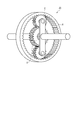
- FIG. 2 is a diagram schematically showing an example of the configuration of the power split mechanism.
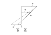
- FIG. 3 is a diagram for explaining an example of the relationship between the sun gear of the power split mechanism, the ring gear, and the rotational speed of the planetary carrier.
- FIG. 4 is a diagram for explaining an example of the relationship between the sun gear of the power split mechanism, the ring gear, and the rotational speed of the planetary carrier.
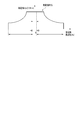
- FIG. 5 is a diagram showing an example of a generator frequency range that can be continuously operated in the vehicle of the embodiment.
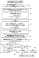
- FIG. 6 is a flow chart for explaining an example of the method of determining the number of revolutions of the internal combustion engine according to the first embodiment.
- FIG. 1 is a block diagram schematically showing the configuration of a vehicle according to the first embodiment.
- the vehicle of the present embodiment includes an internal combustion engine 10, a power split mechanism 20, a generator 30, a converter 40, an inverter 50, a motor 60, a power coupling mechanism 70, a battery 80, wheels WL, a vehicle And an ECU 90.
- the internal combustion engine 10 is a prime mover that generates mechanical energy for driving a vehicle, such as a gasoline engine or a diesel engine.
- Power split device 20 splits mechanical energy Pe generated by internal combustion engine 10 into energy Pg supplied to generator 30 side and energy Pr supplied to wheel WL side (drive train side) for supply. Do.
- FIG. 2 schematically shows an example of the configuration of power split device 20.
- the power split mechanism 20 includes, for example, a sun gear S, a planetary rear gear P circumscribed to the sun gear S, a ring gear R to which the planetary rear gear P is inscribed, and a planetary carrier C rotating along a track of the planetary rear gear P.
- the planetary carrier C is rotated by the mechanical energy Pe generated by the internal combustion engine 10.
- the rotational power of the sun gear S is transmitted to the generator 30.
- the rotational power of the ring gear R is transmitted to the power coupling mechanism 70.
- the generator 30 converts mechanical energy Pg supplied via the sun gear S of the power split mechanism 20 into electrical energy.
- the generator 30 is, for example, a motor provided with a rotor interlocking with the sun gear S and a stator, and outputs three-phase AC power.
- the converter 40 is a control means for controlling the operation of the generator 30, and converts the three-phase AC power output from the generator 30 into DC power for regeneration operation, and DC power supplied from the DC link Are converted into three-phase alternating current power and supplied to the generator 30, and the power generator 30 is made to perform a power running operation.
- Converter 40 is connected to inverter 50 and battery 80 via a DC link.
- the motor 60 is driven by AC power supplied from the inverter 50, converts electrical energy into mechanical energy Pm, and outputs the mechanical energy Pm to the power coupling mechanism 70.
- the power coupling mechanism 70 transmits energy Pout obtained by combining the mechanical energy Pg transmitted from the ring gear R of the internal combustion engine 10 and the mechanical energy Pm supplied from the inverter 50 to an axle (not shown).
- the wheel WL is rotationally driven via an axle.
- a vehicle ECU (electric control unit) 90 is a control unit that controls the internal combustion engine 10, the generator 30, the converter 40, the inverter 50, the motor 60, and the battery 80 to operate in cooperation with one another.
- the vehicle ECU 90 is an arithmetic unit including, for example, at least one processor such as a CPU (central processing unit) or an MPU (micro processing unit) and a memory in which a program executed by the processor is recorded.
- the rotation speed of the planetary carrier C (the rotation speed of the internal combustion engine 10) is constant, the rotation speed of the sun gear S may be lowered to be in the negative direction. That is, the operation of the generator 30 changes from regeneration to power running.
- FIG. 4 is a view for explaining an example of the relationship between the rotational speed of the sun gear S, the ring gear R, and the planetary carrier C of the power split mechanism 20. As shown in FIG. This example is an example of a negative mode in which the planetary carrier C and the ring gear R rotate in the positive direction, and the sun gear S rotates in the negative direction.
- the ratio of the number of teeth Zs of the sun gear S of the power split mechanism 20 to the number of teeth Zr of the ring gear R is 1: 2 and the energy transfer efficiency from the generator 30 to the motor 60 is 85.6%.
- the power transmission efficiency of the entire vehicle will be described by taking, as an example, the case where the respective energy transmission efficiencies of the split mechanism 20 and the power coupling mechanism 70 are 98%.
- the rotational speed of the sun gear S (the rotational speed of the generator 30) becomes -800 rpm to -200 rpm. It shifted in the positive direction. Further, as a result of raising the rotational speed of the internal combustion engine 10 while keeping the output of the internal combustion engine 10 constant, the torque (engine torque) of the planetary carrier C decreases and the torque of the generator 30 also decreases.
- FIG. 5 is a diagram showing an example of a continuously operable generator frequency range in the vehicle of the embodiment.
- the conduction time of a specific element of the converter 40 becomes longer, and further, when the frequency of the power output from the generator 30 becomes 0 Hz (DC), the specific element Current continues to flow, and the element temperature rises. In order to avoid this state, it is desirable to define the range in which the generator 30 operates continuously.
- the rotational speed Ns' of the generator 30 after the rotational speed shift of the internal combustion engine 10 (when the frequency -f0 of the generator 30) is expressed by the following (Equation 3), which is shown in the above (Equation 2)
- the upper limit of the shift amount when the vehicle is operating in the negative mode is expressed by (Expression 5).
- the operating point of the internal combustion engine 10 at which the fuel efficiency of the vehicle is optimum is searched from the trade-off relationship between the power transmission efficiency from the internal combustion engine 10 to the wheel WL and the efficiency of the internal combustion engine 10.
- FIG. 6 is a flow chart for explaining an example of the method of determining the number of revolutions of the internal combustion engine according to the first embodiment.
- the vehicle ECU 90 executes the following method of determining the number of revolutions of the internal combustion engine 10 at least when the vehicle is operating in the negative mode, and the vehicle ECU 90 has a negative direction of rotation of the generator 30. At one time, it is determined that the vehicle is operating in the negative mode.
- the vehicle ECU 90 uses the fuel consumption amount c0 (g / kWh) read from the memory to calculate the fuel consumption amount C_fuel0 (g) per unit time as the following (Equation 6) (step S2).
- the vehicle ECU 90 uses the internal combustion engine torque Tc_n and the rotational speed Nc_n of the internal combustion engine 10 to generate the internal combustion engine output Pe_n required to output the vehicle required output Pout * at the operating point of the internal combustion engine 10 ) (Step S6).
- the vehicle ECU 90 extracts the fuel consumption amount c_n (g / kWh) per unit energy at the operating point (Pe_n, Nc_n) of the internal combustion engine 10 from the map stored in the memory (step S7)
- the fuel consumption amount C_fuel_n per unit time is calculated by the following (Equation 9) (step S8).
- the vehicle ECU 90 updates the rotational speed Nc_n of the internal combustion engine 10 to Nc_n- ⁇ (step S11).
- Vehicle ECU 90 sets ⁇ as a predetermined positive integer. Further, when operating in the positive mode, the rotational speed Nc_n is set to Nc_n + ⁇ .
- the value of ⁇ may be a fixed value, or may be a value that changes according to the value of the rotational speed Nc_n, for example.
- step S9 when the fuel consumption C_fuel_n is not less than the fuel consumption search variable C_fuel_p (when C_fuel_n ⁇ C_fuel_p is not satisfied), the vehicle ECU 90 compares the fuel consumption search variable C_fuel_p with the fuel throughput C_fuel0 (step S12).
- the vehicle ECU 90 sets the initial operating point (Pe0, Nc0) as the operating point of the internal combustion engine 10 (step S14).
- the search variable C_fuel_p and the initial value of the fuel consumption Comparing the _Fuel0 when the search variable C_fuel_p is smaller than the initial value C_fuel0 fuel consumption, and the operating point the rotational speed of the internal combustion engine 10 corresponding to the search variable C_fuel_p, comprises computing means.
- the vehicle ECU 90 selects a plurality of rotation speeds Nc_n in a range in which the internal combustion engine 10 can continuously operate at a predetermined sampling frequency, and selects the plurality of rotation speeds Nc_n selected.
- the fuel consumption amount in the above may be calculated, and the rotation speed Nc_n at which the fuel consumption amount is minimized and the output power Pe_n corresponding thereto may be determined as the operating point (Pe, Nc). Even in that case, the same effect as the above-described embodiment can be obtained.
- the above-described method of determining the rotational speed of the internal combustion engine 10 can be performed both when the vehicle is operating in the positive mode and when operating in the negative mode.
- the power transmission efficiency can be more effectively achieved by determining the rotational speed in consideration of the fuel consumption of the internal combustion engine 10 and the energy transmission efficiency as described above. While improving it, fuel consumption can be suppressed.
Landscapes
- Engineering & Computer Science (AREA)
- Chemical & Material Sciences (AREA)
- Combustion & Propulsion (AREA)
- Transportation (AREA)
- Mechanical Engineering (AREA)
- Automation & Control Theory (AREA)
- Electric Propulsion And Braking For Vehicles (AREA)
- Hybrid Electric Vehicles (AREA)
Priority Applications (3)
| Application Number | Priority Date | Filing Date | Title |
|---|---|---|---|
| PCT/JP2017/041105 WO2019097606A1 (ja) | 2017-11-15 | 2017-11-15 | 車両 |
| EP17931857.1A EP3712026A4 (de) | 2017-11-15 | 2017-11-15 | Fahrzeug |
| CN201780086534.2A CN110300688B (zh) | 2017-11-15 | 2017-11-15 | 车辆 |
Applications Claiming Priority (1)
| Application Number | Priority Date | Filing Date | Title |
|---|---|---|---|
| PCT/JP2017/041105 WO2019097606A1 (ja) | 2017-11-15 | 2017-11-15 | 車両 |
Publications (1)
| Publication Number | Publication Date |
|---|---|
| WO2019097606A1 true WO2019097606A1 (ja) | 2019-05-23 |
Family
ID=66538534
Family Applications (1)
| Application Number | Title | Priority Date | Filing Date |
|---|---|---|---|
| PCT/JP2017/041105 Ceased WO2019097606A1 (ja) | 2017-11-15 | 2017-11-15 | 車両 |
Country Status (3)
| Country | Link |
|---|---|
| EP (1) | EP3712026A4 (de) |
| CN (1) | CN110300688B (de) |
| WO (1) | WO2019097606A1 (de) |
Citations (6)
| Publication number | Priority date | Publication date | Assignee | Title |
|---|---|---|---|---|
| JP2000032608A (ja) * | 1998-07-07 | 2000-01-28 | Denso Corp | ハイブリッド電気自動車の制御装置 |
| JP2010083220A (ja) | 2008-09-30 | 2010-04-15 | Aisin Aw Co Ltd | ハイブリッド制御装置の検査装置及び検査方法 |
| JP2011251615A (ja) * | 2010-06-01 | 2011-12-15 | Toyota Motor Corp | 車両駆動システムの制御装置 |
| JP2013002286A (ja) * | 2011-06-13 | 2013-01-07 | Toyota Central R&D Labs Inc | エンジン制御装置 |
| JP2016088197A (ja) * | 2014-10-31 | 2016-05-23 | トヨタ自動車株式会社 | ハイブッド車両 |
| JP2017226302A (ja) * | 2016-06-22 | 2017-12-28 | 株式会社東芝 | 車両 |
Family Cites Families (11)
| Publication number | Priority date | Publication date | Assignee | Title |
|---|---|---|---|---|
| JP2004011456A (ja) * | 2002-06-04 | 2004-01-15 | Toyota Motor Corp | ハイブリッド車両 |
| US8073610B2 (en) * | 2007-11-07 | 2011-12-06 | GM Global Technology Operations LLC | Method and apparatus to control warm-up of an exhaust aftertreatment system for a hybrid powertrain |
| JP5229088B2 (ja) * | 2009-04-20 | 2013-07-03 | トヨタ自動車株式会社 | ハイブリッド車両の駆動制御装置及び方法 |
| US8425377B2 (en) * | 2010-04-27 | 2013-04-23 | Ford Global Technologies, Llc | Multiple-mode power split hybrid powertrain |
| WO2012090263A1 (ja) * | 2010-12-27 | 2012-07-05 | トヨタ自動車株式会社 | ハイブリッド車両およびその制御方法 |
| JPWO2012104922A1 (ja) * | 2011-02-03 | 2014-07-03 | スズキ株式会社 | ハイブリッド車両の駆動制御装置及びハイブリッド車両 |
| EP2786909A4 (de) * | 2011-12-02 | 2015-12-30 | Toyota Motor Co Ltd | Hybridfahrzeug |
| US8996223B2 (en) * | 2012-01-19 | 2015-03-31 | Toyota Jidosha Kabushiki Kaisha | Engine operation start control device of hybrid vehicle |
| US9643591B2 (en) * | 2012-02-07 | 2017-05-09 | Toyota Jidosha Kabushiki Kaisha | Speed change control system and speed change control method for hybrid vehicle |
| US9638096B2 (en) * | 2012-04-25 | 2017-05-02 | Toyota Jidosha Kabushiki Kaisha | Vehicle control apparatus |
| US8862297B2 (en) * | 2012-08-09 | 2014-10-14 | GM Global Technology Operations LLC | Enhanced method for choosing optimal engine speed and torque |
-
2017
- 2017-11-15 EP EP17931857.1A patent/EP3712026A4/de not_active Withdrawn
- 2017-11-15 CN CN201780086534.2A patent/CN110300688B/zh not_active Expired - Fee Related
- 2017-11-15 WO PCT/JP2017/041105 patent/WO2019097606A1/ja not_active Ceased
Patent Citations (6)
| Publication number | Priority date | Publication date | Assignee | Title |
|---|---|---|---|---|
| JP2000032608A (ja) * | 1998-07-07 | 2000-01-28 | Denso Corp | ハイブリッド電気自動車の制御装置 |
| JP2010083220A (ja) | 2008-09-30 | 2010-04-15 | Aisin Aw Co Ltd | ハイブリッド制御装置の検査装置及び検査方法 |
| JP2011251615A (ja) * | 2010-06-01 | 2011-12-15 | Toyota Motor Corp | 車両駆動システムの制御装置 |
| JP2013002286A (ja) * | 2011-06-13 | 2013-01-07 | Toyota Central R&D Labs Inc | エンジン制御装置 |
| JP2016088197A (ja) * | 2014-10-31 | 2016-05-23 | トヨタ自動車株式会社 | ハイブッド車両 |
| JP2017226302A (ja) * | 2016-06-22 | 2017-12-28 | 株式会社東芝 | 車両 |
Non-Patent Citations (1)
| Title |
|---|
| See also references of EP3712026A4 |
Also Published As
| Publication number | Publication date |
|---|---|
| EP3712026A4 (de) | 2021-06-30 |
| CN110300688B (zh) | 2022-04-26 |
| CN110300688A (zh) | 2019-10-01 |
| EP3712026A1 (de) | 2020-09-23 |
Similar Documents
| Publication | Publication Date | Title |
|---|---|---|
| JP6010365B2 (ja) | ハイブリッド自動車のトルク制御方法及びそのシステム | |
| CN103380043B (zh) | 混合动力车辆的驱动控制装置 | |
| CN103380047B (zh) | 混合动力车辆的驱动控制装置 | |
| US20180236996A1 (en) | Hybrid vehicle | |
| US10259446B1 (en) | Hybrid vehicle | |
| CN105253138B (zh) | 混合动力总成和用于控制其的方法 | |
| JP4803101B2 (ja) | ハイブリッド車両の動力出力装置 | |
| CN103517841A (zh) | 混合动力车辆的发动机启动控制装置 | |
| JP2016119809A (ja) | モータ制御装置および制御方法 | |
| JP5077830B2 (ja) | ハイブリッド車の制御装置 | |
| JP2015202727A (ja) | 車両 | |
| WO2011125862A1 (ja) | ハイブリッド車両制御装置 | |
| US10532732B2 (en) | Hybrid vehicle and control method therefor | |
| US10245958B2 (en) | Hybrid vehicle and control method therefor | |
| US10549746B2 (en) | Hybrid vehicle | |
| JP4813419B2 (ja) | ハイブリッド車の制御装置 | |
| JP2015202806A (ja) | 車両制御装置 | |
| JP6812895B2 (ja) | ハイブリッド車両 | |
| JP6786270B2 (ja) | 車両 | |
| WO2019097606A1 (ja) | 車両 | |
| US10745000B2 (en) | Hybrid vehicle and control method therefor | |
| CN103895638B (zh) | 用于混合动力车辆的控制设备和控制方法 | |
| WO2018037715A1 (ja) | ハイブリッド車両システム | |
| JP6874638B2 (ja) | ハイブリッド自動車 | |
| JP2011156984A (ja) | ハイブリッド車両 |
Legal Events
| Date | Code | Title | Description |
|---|---|---|---|
| 121 | Ep: the epo has been informed by wipo that ep was designated in this application |
Ref document number: 17931857 Country of ref document: EP Kind code of ref document: A1 |
|
| NENP | Non-entry into the national phase |
Ref country code: DE |
|
| ENP | Entry into the national phase |
Ref document number: 2017931857 Country of ref document: EP Effective date: 20200615 |
|
| NENP | Non-entry into the national phase |
Ref country code: JP |