WO2019097608A1 - Dispositif médical - Google Patents
Dispositif médical Download PDFInfo
- Publication number
- WO2019097608A1 WO2019097608A1 PCT/JP2017/041107 JP2017041107W WO2019097608A1 WO 2019097608 A1 WO2019097608 A1 WO 2019097608A1 JP 2017041107 W JP2017041107 W JP 2017041107W WO 2019097608 A1 WO2019097608 A1 WO 2019097608A1
- Authority
- WO
- WIPO (PCT)
- Prior art keywords
- electrode
- jaw
- jaws
- shaft
- medical device
- Prior art date
- Legal status (The legal status is an assumption and is not a legal conclusion. Google has not performed a legal analysis and makes no representation as to the accuracy of the status listed.)
- Ceased
Links
Images




Classifications
-
- A—HUMAN NECESSITIES
- A61—MEDICAL OR VETERINARY SCIENCE; HYGIENE
- A61B—DIAGNOSIS; SURGERY; IDENTIFICATION
- A61B18/00—Surgical instruments, devices or methods for transferring non-mechanical forms of energy to or from the body
- A61B18/04—Surgical instruments, devices or methods for transferring non-mechanical forms of energy to or from the body by heating
- A61B18/08—Surgical instruments, devices or methods for transferring non-mechanical forms of energy to or from the body by heating by means of electrically-heated probes
- A61B18/082—Probes or electrodes therefor
- A61B18/085—Forceps, scissors
-
- A—HUMAN NECESSITIES
- A61—MEDICAL OR VETERINARY SCIENCE; HYGIENE
- A61B—DIAGNOSIS; SURGERY; IDENTIFICATION
- A61B18/00—Surgical instruments, devices or methods for transferring non-mechanical forms of energy to or from the body
- A61B18/04—Surgical instruments, devices or methods for transferring non-mechanical forms of energy to or from the body by heating
- A61B18/12—Surgical instruments, devices or methods for transferring non-mechanical forms of energy to or from the body by heating by passing a current through the tissue to be heated, e.g. high-frequency current
- A61B18/14—Probes or electrodes therefor
- A61B18/1442—Probes having pivoting end effectors, e.g. forceps
- A61B18/1445—Probes having pivoting end effectors, e.g. forceps at the distal end of a shaft, e.g. forceps or scissors at the end of a rigid rod
-
- A—HUMAN NECESSITIES
- A61—MEDICAL OR VETERINARY SCIENCE; HYGIENE
- A61B—DIAGNOSIS; SURGERY; IDENTIFICATION
- A61B18/00—Surgical instruments, devices or methods for transferring non-mechanical forms of energy to or from the body
- A61B18/04—Surgical instruments, devices or methods for transferring non-mechanical forms of energy to or from the body by heating
- A61B18/12—Surgical instruments, devices or methods for transferring non-mechanical forms of energy to or from the body by heating by passing a current through the tissue to be heated, e.g. high-frequency current
- A61B18/14—Probes or electrodes therefor
-
- A—HUMAN NECESSITIES
- A61—MEDICAL OR VETERINARY SCIENCE; HYGIENE
- A61B—DIAGNOSIS; SURGERY; IDENTIFICATION
- A61B18/00—Surgical instruments, devices or methods for transferring non-mechanical forms of energy to or from the body
- A61B2018/00053—Mechanical features of the instrument of device
- A61B2018/00059—Material properties
- A61B2018/00071—Electrical conductivity
- A61B2018/00083—Electrical conductivity low, i.e. electrically insulating
-
- A—HUMAN NECESSITIES
- A61—MEDICAL OR VETERINARY SCIENCE; HYGIENE
- A61B—DIAGNOSIS; SURGERY; IDENTIFICATION
- A61B18/00—Surgical instruments, devices or methods for transferring non-mechanical forms of energy to or from the body
- A61B2018/00053—Mechanical features of the instrument of device
- A61B2018/00059—Material properties
- A61B2018/00089—Thermal conductivity
- A61B2018/00095—Thermal conductivity high, i.e. heat conducting
-
- A—HUMAN NECESSITIES
- A61—MEDICAL OR VETERINARY SCIENCE; HYGIENE
- A61B—DIAGNOSIS; SURGERY; IDENTIFICATION
- A61B18/00—Surgical instruments, devices or methods for transferring non-mechanical forms of energy to or from the body
- A61B2018/00053—Mechanical features of the instrument of device
- A61B2018/00059—Material properties
- A61B2018/00089—Thermal conductivity
- A61B2018/00101—Thermal conductivity low, i.e. thermally insulating
-
- A—HUMAN NECESSITIES
- A61—MEDICAL OR VETERINARY SCIENCE; HYGIENE
- A61B—DIAGNOSIS; SURGERY; IDENTIFICATION
- A61B18/00—Surgical instruments, devices or methods for transferring non-mechanical forms of energy to or from the body
- A61B18/04—Surgical instruments, devices or methods for transferring non-mechanical forms of energy to or from the body by heating
- A61B18/12—Surgical instruments, devices or methods for transferring non-mechanical forms of energy to or from the body by heating by passing a current through the tissue to be heated, e.g. high-frequency current
- A61B18/14—Probes or electrodes therefor
- A61B18/1442—Probes having pivoting end effectors, e.g. forceps
- A61B2018/1452—Probes having pivoting end effectors, e.g. forceps including means for cutting
- A61B2018/1457—Probes having pivoting end effectors, e.g. forceps including means for cutting having opposing blades cutting tissue grasped by the jaws, i.e. combined scissors and pliers
Definitions
- the present invention relates to a medical device that treats a treatment target using treatment energy.
- US 2017/0000556 A1 discloses a medical device that holds a treatment target such as a living tissue between a pair of holding pieces and treats a treatment target held using treatment energy such as a high frequency current.
- the pair of gripping pieces includes a pair of gripping surfaces facing each other.
- An electrode is provided on each of the gripping surfaces, and each of the electrodes is supplied with electrical energy (high frequency power). By supplying electric energy (high frequency power) to each of the electrodes, a high frequency current flows between the grasping pieces through the treatment object to treat the treatment object.
- one of the gripping pieces may be provided with a wiper structure.
- the gripping piece provided with the wiper structure comprises a jaw and a swinging part.
- the swinging portion is swingably attached to the jaw via a pin.
- the swinging portion is provided with an electrode.
- the electrodes are supplied with electrical energy (high frequency power) via the jaws and pins.
- the jaws form part of an electrical pathway that supplies electrical energy to the electrodes, and the jaws are prone to heat. Also, the heat generated at the electrode is easily transmitted to the jaws.
- the present invention has been made focusing on the above-mentioned problems, and an object of the present invention is to provide a medical device capable of suppressing the generation of heat in the jaws and the transfer of heat to the jaws.
- a medical device in order to achieve the above object, includes a first electrode, a jaw opening and closing with respect to the first electrode, and a treatment surface facing the first electrode.
- An electrode holder mounted on the second electrode so as to be swingable relative to the jaw, and attached to the second electrode from the side opposite to the treatment surface, and having a lower thermal conductivity than the second electrode; And an aggregate provided on the electrode holder, electrically insulated from the second electrode, and having a bending strength higher than that of the electrode holder.
- FIG. 1 is a view schematically showing a medical device according to the first embodiment.
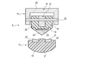
- FIG. 2 is a view schematically showing a part of the configuration of the end effector according to the first embodiment in a cross section passing through a longitudinal axis.
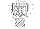
- FIG. 3 is a view schematically showing the configuration of the end effector according to the first embodiment in a cross section intersecting the longitudinal axis.
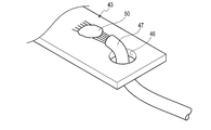
- FIG. 4 is a perspective view schematically showing a connection portion between the second electrode and the electrical wiring according to the first embodiment.
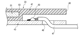
- FIG. 5 is a view schematically showing, in a cross section intersecting the width direction, the connection portion between the second electrode and the electrical wiring according to the first embodiment.
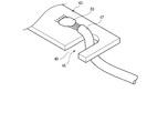
- FIG. 6 is a perspective view schematically showing a connection portion between a second electrode and an electrical wiring according to a modification of the first embodiment.
- FIG. 7 is a view schematically showing, in a cross section intersecting the longitudinal axis, the connection structure between the shaft and the second grip piece according to the first embodiment.
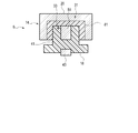
- FIG. 8 is a view schematically showing a configuration of an end effector according to a first modified example of the first embodiment in a cross section intersecting a longitudinal axis.
- FIG. 9 is a view schematically showing a configuration of a second gripping piece of an end effector according to a second modified example of the first embodiment in a cross section intersecting with the width direction.
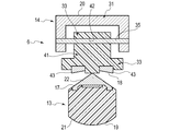
- FIG. 10 is a view schematically showing a configuration of an end effector according to a third modified example of the first embodiment in a cross section intersecting the longitudinal axis.
- FIG. 11 is a view schematically showing the configuration of the end effector according to the first reference example in a cross section intersecting the longitudinal axis.
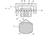
- FIG. 12 is a view schematically showing the configuration of the end effector according to the second reference example in a cross section intersecting the longitudinal axis.
- FIG. 1 is a view showing a treatment tool 1 which is a medical device of the present embodiment.
- the treatment instrument 1 includes a holdable housing 4 and a cylindrical shaft 5 connected to the housing 4.
- One end of a cable 7 is connected to the housing 4.
- the other end of the cable 7 is detachably connected to the power supply 3.
- the shaft 5 defines a longitudinal axis C.
- the direction along the longitudinal axis C is taken as the longitudinal direction.
- One side in the longitudinal direction is the distal end side (arrow C1 side in FIG. 1), and the opposite side to the distal end side is the proximal end side (arrow C2 side in FIG. 1).
- the shaft 5 is extended along the longitudinal axis C from the proximal end side to the distal end side, and is connected to the distal end side of the housing 4.
- An end effector 6 is provided at the tip of the shaft 5.
- the end effector 6 comprises a first gripping piece 13 and a second gripping piece 14. Between the first grip piece 13 and the second grip piece 14 can be opened and closed.
- the first gripping piece 13 is fixed to the shaft 5, and the second gripping piece 14 is rotatably attached to the shaft 5 with respect to the first gripping piece 13.
- both the first gripping piece 13 and the second gripping piece 14 are rotatably attached to the shaft 5.
- the first gripping piece 13 includes a treatment surface (facing surface) 17 opposed to the second gripping piece 14 and a back surface 19 facing the opposite side to the treatment surface 17.
- the second gripping piece 14 includes a treatment surface (facing surface) 18 facing the treatment surface 17 of the first gripping piece 13 and a back surface 20 facing the treatment surface 18.
- the open / close direction of the end effector 6 intersects (is substantially perpendicular to) the longitudinal axis C.
- the side in which the second gripping piece 14 opens with respect to the first gripping piece 13 is the opening direction (arrow Y1) of the second gripping piece 14, and the second gripping piece 14 is The side closed with respect to the first gripping piece 13 is taken as the closing direction (arrow Y2) of the second gripping piece 14.
- the width direction of the end effector 6 is a direction intersecting (vertically or substantially perpendicular) to the longitudinal axis C and intersecting (vertically or substantially perpendicular) to the opening / closing direction of the end effector 6 .
- the housing 4 includes a housing body 15 and a grip (fixed handle) 11.
- the housing body 15 extends along the longitudinal axis C.
- the grip 11 extends from the housing body 15 in a direction away from the longitudinal axis C.
- the shaft 5 is connected to the housing body 15 from the tip side.
- a movable handle 12 is rotatably attached to the housing body 15.
- the movable handle 12 is located on the side where the grip 11 is located with respect to the longitudinal axis C, and is located on the distal side with respect to the grip 11 in the present embodiment.
- the movable handle 12 is pivoted relative to the housing body 15 so that the movable handle 12 opens or closes relative to the grip 11.
- an operation for opening or closing the end effector 6 as described above is input at the movable handle 12 which is an open / close operation input unit.
- the movable handle 12 and the second grip piece 14 are connected via a movable member 16 which extends along the longitudinal axis C inside the shaft 5.
- the movable member 16 moves along the longitudinal axis C relative to the shaft 5 and the housing 4 by opening or closing the movable handle 12 which is an open / close operation input unit with respect to the grip 11, and the second grip piece 14 is a shaft 5 and the first gripping piece 13 are pivoted. Thereby, the holding pieces 13 and 14 are opened or closed.
- the treatment target is held between the holding pieces 13 and 14 by closing between the holding pieces 13 and 14.
- the movable handle 12 is proximal to the grip 11. In another embodiment, the movable handle 12 is located on the opposite side of the longitudinal axis C to the side where the grip 11 is located, and intersects the longitudinal axis C in the opening operation and the closing operation ( Vertically or nearly vertically).
- an operating member such as a rotation knob is attached to the housing 4.
- the shaft 5 and the end effector 6 together rotate with respect to the housing 4 about the longitudinal axis C.
- the power supply device 3 includes a high frequency power supply and a thermal power supply.
- the high frequency power supply includes a waveform generator, a conversion circuit, a transformer, and the like, and converts power from a battery power supply or an outlet power supply to high frequency power. Further, as described later, each of the first grip piece 13 and the second grip piece 14 is at least partially formed of a conductive material.
- the high frequency power source is electrically connected to each of the first gripping piece 13 and the second gripping piece 14 through an electrical path provided through the inside of the cable 7, the inside of the housing 4 and the inside of the shaft 5. Ru.
- the high frequency power supply outputs the converted high frequency power through the aforementioned electric path, and supplies the first holding piece 13 and the second holding piece 14 with high frequency power as electric energy.
- the thermal power supply includes a conversion circuit, a transformer, and the like, and converts power from a battery power supply or a wall outlet power supply into direct current power or alternating current power. Further, a heat source (heating element) 25 described later is provided on at least one of the first grip piece 13 and the second grip piece 14. The thermal power source is electrically connected to the heat source 25 via an electrical path provided through the interior of the cable 7, the interior of the housing 4 and the interior of the shaft 5. The thermal power supply outputs the converted power through the above-described electric path to supply the heat source 25 with electrical energy.
- the housing main body 15 of the housing 4 is provided with an operation button 10 which is an energy operation input unit.
- an operation button 10 which is an energy operation input unit.
- electric energy is supplied to the end effector 6 from each of the high frequency power source and the thermal power source and held. High frequency current and heat are given to treatment subject as treatment energy.
- a foot switch electrically connected to the power supply 3 is provided separately from the treatment instrument 1 instead of or in addition to the operation button 10.
- the housing 4 is provided with a plurality of operation buttons 10.
- a certain operation button 10 for example, only the high frequency current is given as treatment energy to the treatment object.
- a high frequency current and heat are given to the treatment target as treatment energy.
- FIG. 2 is a view showing the tip of the shaft 5 and the end effector 6.
- FIG. 2 is a view showing a part in a cross section (vertical or substantially perpendicular) passing through the longitudinal axis C and intersecting with the width direction of the end effector 6.
- FIG. 3 is a view showing a closed state between the gripping pieces 13 and 14 in a cross section (vertical or substantially vertical) intersecting the longitudinal axis C.
- the first gripping piece 13 includes a support 21 and a conductive member (blade) 22.
- Each of the support 21 and the conductive member 22 extends in the direction along the longitudinal axis C from the proximal end to the distal end of the gripping piece 13.
- the support 21 is fixed to the shaft 5.
- the support 21 is formed of, for example, a material having electrical insulation and low thermal conductivity.
- the support 21 is formed of, for example, a resin.
- the support body 21 may be formed by insert-molding resin to a metal core material.
- the conductive member 22 is attached to the support 21 from the side of the grip piece 14.
- the conductive member 22 has conductivity.
- the conductive member 22 is formed of, for example, a material having high thermal conductivity, such as a copper alloy or an aluminum alloy.
- the conductive member 22 forms at least a part of the treatment surface 17. In the present embodiment, the treatment surface 17 is formed to be closer to the gripping piece 14 toward the center in the width direction.
- the conductive member 22 is connected to one end of an electrical path formed of an electrical wiring or the like. This electrical path extends through the interior of the shaft 5, the interior of the housing 4 and the interior of the cable 7, and the other end is connected to the high frequency power supply of the power supply 3. Thereby, the conductive member 22 and the high frequency power source are electrically connected, and high frequency power can be supplied from the high frequency power source to the conductive member 22 as electric energy.
- the conductive member 22 functions as a first electrode by being supplied with electrical energy.
- the first grip piece 13 includes a heat source 25.
- the heat source 25 is attached to the conductive member 22 from the side opposite to the treatment surface 17.
- the heat source 25 is provided in a range from the proximal end to the distal end of the gripping piece 13 in the longitudinal direction.
- the heat source 25 is a heating wire attached to the conductive member 22 or a heating pattern printed on the conductive member 22 or the like, and is formed of, for example, a nichrome alloy or a stainless steel alloy.
- the heat source 25 is electrically isolated from the conductive member 22.
- the heat source 25 is connected to one end of an electrical path formed of an electrical wiring or the like. This electrical path extends through the interior of the shaft 5, the interior of the housing 4 and the interior of the cable 7, and the other end is connected to the thermal power supply of the power supply 3. As a result, the heat source 25 and the heat source are electrically connected, and electrical energy can be supplied from the heat source to the heat source 25.
- the supply of electric energy from the heat source to the heat source 25 generates heat in the heat source 25.
- the heat generated by the heat source 25 is transmitted to the conductive member 22 and applied as treatment energy from the treatment surface 17 to the treatment target held between the holding pieces 13 and 14.
- the second grip piece 14 includes a jaw (support) 31 and a swinging portion 33.
- the jaws 31 and the swinging portion 33 extend from the distal end of the gripping piece 14 to the proximal end along the extending direction of the gripping piece 14.
- the swinging portion 33 is swingable with respect to the jaws 31.
- the jaws 31 extend along the longitudinal axis C in a state where the gripping piece 14 is closed with respect to the gripping piece 13. That is, in the state where the gripping piece 14 is closed with respect to the gripping piece 13, the extending direction of the jaws 31 is parallel or substantially parallel to the longitudinal axis C.
- the jaw 31 has a U-shape in which a cross-sectional shape intersecting (perpendicularly or substantially perpendicular) to the extending direction is open toward the gripping piece 13.
- the jaws 31 also have an inward facing surface 32.
- the inward facing surface 32 faces away from the back surface 20.
- the jaws 31 are preferably formed of, for example, a metal such as stainless steel, but may be formed of a resin or the like.
- a cover 38 is attached to the jaws 31.
- the cover 38 is in close contact with the jaws 31 from the rear surface 20 side.
- the cover 38 is formed of a material having a thermal conductivity smaller than that of the jaws 31.
- the cover 38 is formed of, for example, a resin.
- the cover 38 forms the back surface 20 of the gripping piece 14. The cover 38 may not be provided.
- the swinging portion 33 is attached to the jaw 31 from the side of the gripping piece 13.
- the swinging portion 33 is attached to the jaw 31 via the swing pin 35.
- the swing pin 35 is provided at the central portion of the gripping piece 14 in the extending direction of the gripping piece 14 and extends along the width direction.
- the swing pin 35 is made of, for example, metal.
- the rocking portion 33 is rockable with respect to the jaw 31 with the rocking pin 35 as a rocking shaft.
- the swinging portion 33 forms the treatment surface 18 of the gripping piece 14.
- the swinging portion 33 has a back surface 34.
- the back surface 34 faces away from the treatment surface 18.
- the back surface 34 of the rocking portion 33 is opposed to the inward facing surface 32 of the jaw 31.
- the swinging portion 33 includes an electrode holder 41.
- the electrode holder 41 is extended from the tip end of the jaw 31 to the base end along the extension direction of the grip piece 14.
- the electrode holder 41 is formed of a material that has electrical insulation and low thermal conductivity.
- the electrode holder 41 is formed of, for example, a resin.
- the jaws 31 are provided with insertion holes 37.
- the insertion hole 37 is formed in the jaw 31 along the width direction.
- the insertion holes 37 are formed in both side walls of the jaw 31 in the width direction, and penetrate the side wall of the jaw 31.
- the electrode holder 41 is provided with an insertion hole 42.
- the insertion hole 42 is formed along the width direction in the electrode holder 41.
- the swing pin 35 is inserted through the insertion hole 37 of the jaw 31 and the insertion hole 42 of the electrode holder 41.
- the electrode holder 41 is attached to the jaw 31 by inserting the rocking pin 35 into the insertion holes 37 and 42.
- a conductive member (second electrode) 43 is attached to the electrode holder 41.
- the conductive member 43 is attached to the electrode holder 41 from the side of the gripping piece 13.
- the conductive member 43 is extended along the extending direction of the gripping piece 14 and extends over the range from the distal end of the jaw 31 to the proximal end.
- the conductive member 43 forms a part of the treatment surface 17.
- the conductive member 43 is conductive.
- the conductive member 43 is formed of, for example, a metal such as stainless steel.
- the conductive member 43 is electrically insulated from the jaw 31 and the swing pin 35 via the electrode holder 41.
- the conductive member 43 has a thermal conductivity larger than that of the electrode holder 41. Therefore, the electrode holder 41 has a thermal conductivity smaller than that of the conductive member 43.
- the electrode holder 41 includes an abutting portion 45.
- the contact portion 45 is provided at the central position of the grip piece 14 in the width direction.
- the contact portion 45 protrudes from the conductive member 43 toward the gripping piece 13 side.
- the contact portion 45 forms a central portion of the treatment surface 17 in the width direction.
- the contact portion 45 of the electrode holder 41 abuts on the treatment surface 17 of the gripping piece 13 in a state where the gap between the gripping pieces 13 and 14 is closed. In this state, a gap is formed between the conductive member 22 and the conductive member 43, and the conductive member 43 does not contact the conductive member 22. Therefore, in a state where the conductive member 22 and the conductive member 43 function as electrodes, a short circuit in an electric circuit in which high frequency power is output from the power supply 3 to the conductive member 22 and the conductive member 43 is effectively prevented.
- An aggregate 51 is attached to the electrode holder 41.
- the aggregate 51 is extended along the extending direction of the grip piece 14 and extends over the range from the tip end of the jaw 31 to the base end.
- the aggregate 51 is disposed inside the electrode holder 41.
- the electrode holder 41 is in close contact with the aggregate 51 in the width direction from the outside. Therefore, the electrode holder 41 covers at least a part of the aggregate 51.
- the aggregate 51 is separated from the conductive member 43 via the electrode holder 41. Therefore, the aggregate 51 is electrically insulated from the conductive member 43 via the electrode holder 41.
- the aggregate 51 is formed of a material having a bending strength greater than that of the electrode holder 41.
- the electrode holder 41 is formed, for example, of metal or ceramic.
- an insertion hole 52 is provided in the aggregate 51.
- the insertion hole 52 penetrates the aggregate 51 in the width direction.
- the swing pin 35 is inserted into the insertion hole 52. That is, the swing pin 35 penetrates the aggregate 51.
- the aggregate 51 is supported by the jaw 31 together with the electrode holder 41 via the swing pin 35.
- the aggregate 51 is pivotable relative to the jaws 31 together with the electrode holder 41.
- the electrode holder 41 includes projections provided on both sides of the aggregate 51 in the width direction, and the projections project toward the jaws 31 in the electrode holder 41.
- the penetration hole 42 is formed in each of arium
- the aggregate 51 includes the protrusions 54 and 55.
- the protrusions 54 and 55 protrude from the back surface 34 of the swinging portion 33 toward the inward facing surface 32 of the jaw 31.
- the projecting portion 54 is provided on the proximal side of the swinging shaft (35) in the extending direction of the gripping piece 14.
- the protrusion 54 abuts on the inward facing surface 32 of the jaw 31 when a portion closer to the jaw 31 than the rocking shaft (35) in the rocking portion 33 is.
- the projecting portion 55 is located on the tip side of the swinging shaft (35) in the extending direction of the gripping piece 14.
- the protrusion 55 abuts on the inward facing surface 32 of the jaw 31 when the portion on the tip end side of the swinging shaft 33 approaches the jaw 31 in the swinging portion 33.
- the aggregate 51 is exposed from the electrode holder 41 at the portion of the swinging portion 33 that abuts against the jaw 31 by swinging with respect to the jaw 31. Therefore, when the swinging portion 33 and the jaw 31 abut on each other, the aggregate 51 comes in contact with the jaw 31. That is, in the swinging portion 33, the contact portion with the jaw 31 is formed by the aggregate 51.
- FIG. 4 and FIG. 5 are views showing the base end of the rocking portion 33.
- FIG. 4 is a perspective view
- FIG. 5 is a view showing a cross section perpendicular or substantially perpendicular to the width direction.
- one end of an electrical wiring (lead wire) 47 is connected to the proximal end of the conductive member 43.
- the electrical wiring 47 is extended through the inside of the shaft 5, the inside of the housing 4 and the inside of the cable 7, and the other end is electrically connected to the high frequency power supply of the power supply 3.
- the conductive member 43 and the high frequency power source are electrically connected, and high frequency power can be supplied from the high frequency power source to the conductive member 43 as electrical energy.
- the conductive member 43 functions as a second electrode by being supplied with electrical energy.
- An insertion hole 46 is formed at the proximal end of the conductive member 43.
- the insertion hole 46 penetrates the conductive member 43 from the treatment surface 18 side toward the back surface 20 side.
- the insertion hole 46 is located in the vicinity of the connection portion 50 between the electrical wiring 47 and the conductive member 43.
- the electrical wiring 47 is extended from the inside of the shaft 5 to the tip side and is inserted into the insertion hole 46.
- the power supply device 3 outputs high frequency power as electric energy from the high frequency power source based on the operation of the operation button 10.
- the output high frequency power is supplied to the conductive member 22 of the gripping piece 13 through the above-described electrical path, and is also supplied to the conductive member 43 of the gripping piece 14 through the above-described electrical path.
- the conductive member 22 and the conductive member 43 function as electrodes having different potentials with respect to each other.
- the conductive member 22 and the conductive member 43 function as an electrode in a state in which the treatment target is held between the holding pieces 13 and 14 so that a high frequency current flows between the conductive member 22 and the conductive member 43 through the treatment target.
- a high frequency current is applied to the subject as treatment energy.
- the electrode holder 41 is provided over a range from the aggregate 51 to the proximal end side in the extending direction of the gripping piece 14. Therefore, the proximal end 48 of the electrode holder 41 is positioned more proximal than the proximal end 53 of the aggregate 51. The proximal end 48 of the electrode holder 41 is located on the distal side of the connecting portion 50 between the conductive member 43 and the electrical wiring 47.
- the aggregate 51 is extended in the extending direction of the gripping piece 14 to a position closer to the tip end than the connection portion 50 between the conductive member 43 and the electric wiring 47. Therefore, the proximal end 53 of the aggregate 51 is positioned more distal than the connecting portion 50.
- the insertion hole 46 is provided with the opening part 49 opened toward one side of the width direction. In this case, when connecting the electrical wire 47 to the conductive member 43, the electrical wire 47 can be inserted into the insertion hole 46 through the opening 49.
- FIG. 7 is a view showing a connecting structure of the shaft 5 and the second grip piece 14.
- a cross section (substantially perpendicular) intersecting the longitudinal axis C has a U shape opened toward the second grip piece 14 side.
- a cross section (substantially perpendicular) of the proximal end portion of the jaw 31 of the second gripping piece 14 in the extending direction of the gripping piece 14 is opened toward the shaft 5 side (the first gripping piece 13 side) It becomes U-shaped.
- the second gripping pieces 14 are disposed on both outer sides of the shaft 5 in the width direction. At this time, the surface of the shaft 5 facing outward in the width direction and the surface of the second grip piece 14 facing inward in the width direction face each other in a separated state.
- An engagement hole 58 is formed at the tip of the shaft 5.
- the engagement hole 58 is formed at the tip of the shaft 5 along the width direction.
- the engagement holes 58 are provided on both side surfaces in the width direction at the tip end portion of the shaft 5 and penetrate the side surface of the shaft 5.
- An engagement hole 39 is formed at the proximal end of the jaw 31 of the second grip piece 14.
- the engagement holes 39 are formed in the jaws 31 along the width direction.
- the engagement holes 39 are provided on both side surfaces of the proximal end of the jaw 31 and penetrate the side surface of the jaw 31.
- the pivot pin 61 is inserted into the engagement hole 58 and the engagement hole 39.
- the pivot pin 61 is extended along the width direction, and is inserted into each of the engagement hole 58 and the engagement hole 39.
- the second grip piece 14 is pivotably attached to the tip of the shaft 5.
- a washer 63 is disposed between the shaft 5 and the second grip piece 14.
- the washer 63 is a ring-shaped thin metal plate and has thermal conductivity.
- the pivot pin 61 is inserted through the washer 63.
- the washer 63 is preferably disposed at a position not in contact with the pivot pin 61.
- the washer 63 is a spring washer having elasticity.
- the washer 63 is in contact with the shaft 5 and the second grip piece 14 respectively.
- the washer 63 is biased by the shaft 5 and the second grip piece 14 and can slide relative to the shaft 5 and the second grip piece 14 respectively.
- the washer 63 can transfer heat between the second gripping piece 14 and the shaft 5.
- the first grip piece 13 is supported by the shaft 5.
- the heat generated by the heat source 25 is transmitted to the shaft 5 via the first grip piece 13.
- the washer 63 is provided between the shaft 5 and the second grip piece 14 so that the first grip piece 13 and the second grip piece 14 can be interposed between the first grip piece 13 and the second grip piece 14 via the washer 63 and the shaft 5. Heat is transferred.
- the end effector 6 When performing treatment using the treatment tool 1, first, the end effector 6 is inserted into a body cavity such as the abdominal cavity. Then, a treatment target such as a blood vessel is disposed between the pair of grasping pieces 13 and 14, and the end effector 6 is closed. Thereby, the treatment target is gripped between the gripping pieces 13 and 14. At this time, the treatment target is gripped between the treatment surface 17 and the treatment surface 18 provided on the swinging portion 33.
- the swinging portion 33 can swing around the swing pin 35 with respect to the jaw 31.
- the grasping of the treatment object between the gripping pieces 13 and 14 is more efficient than in the case where the proximal end of the treatment surface 18 abuts on the treatment object
- the forces are nearly identical. That is, even when the position of the treatment surface 18 in contact with the treatment target in the extending direction of the gripping pieces 14 changes, the gripping force between the gripping pieces 13 and 14 is maintained substantially uniform.
- the operation input for supplying the electric energy from the power supply device 3 to the treatment tool 1 is performed, whereby the high frequency current and the heat source 25 are transmitted.
- the heat of at least one is applied as treatment energy to the treatment object grasped between the grasping pieces 13 and 14.
- electrical energy (high frequency power) is supplied to the conductive member 43 via the electrical wiring 47.
- the electrode holder 41 is provided to electrically insulate between the jaw 31 and the aggregate 51 and the conductive member 43 of the grip piece 14. Therefore, electrical energy (high frequency power) is supplied to the conductive member 43 without passing through the jaws 31. That is, the jaws 31 are electrically isolated from the electrical path that supplies the conductive member 43 with electrical energy (high frequency power). Therefore, even when electric energy (high frequency power) is supplied to the conductive member 43, the jaws 31 and the swing pin 35 are not supplied with electric energy (high frequency power). For this reason, heat generated in the jaws 31 is suppressed as compared to the case where the jaws 31 form a part of the electrical path.
- the electrode holder 41 is formed of a material having a low thermal conductivity. For this reason, it is suppressed that the heat which generate
- the aggregate 51 is provided in the swinging portion 33, and the aggregate 51 is extended along the extending direction of the grip piece 14. Further, the aggregate 51 is formed of a material having a high bending strength (tensile strength). For this reason, even when the electrode holder 41 is formed of a material having a low thermal conductivity, such as a resin, the decrease in the bending strength of the rocking portion 33 can be suppressed by providing the aggregate 51. Thereby, the transmission of heat to the jaws 31 can be suppressed, and the durability (strength resistance) of the rocking portion 33 can be maintained.
- the contact portion of the swinging portion 33 with the jaw 31 is formed by the aggregate 51. Therefore, even when the electrode holder 41 is formed of a material having a low thermal conductivity such as a resin, the durability (strength resistance) of the rocking portion 33 is further ensured.
- a cover 38 formed of a material having a low thermal conductivity is attached to the jaws 31.
- the back surface 20 of the gripping piece 14 is formed by the cover 38. For this reason, residual heat from the back surface 20 of the gripping piece 14 is prevented from affecting the treatment.
- the proximal end 53 of the aggregate 51 is disposed on the distal side with respect to the connection portion 50 between the conductive member 43 and the electrical wiring 47. As a result, the contact between the aggregate 51 and the electrical wiring 47 is prevented, and the workability when connecting the electrical wiring 47 to the conductive member 43 is improved.
- the electrical wiring 47 is directly connected to the conductive member 43, and the electrical energy (high frequency power) is supplied to the conductive member 43 without passing through the jaws 31.
- the jaws 31 rotate with respect to the shaft 5 and the swinging portion 33 swings with respect to the jaws 31.
- a force (peel force) to peel the electric wire 47 from the conductive member 43 acts on the connection portion 50. Since the strength of the electrical wiring 47 is particularly low at the connection portion 50, it is required to reduce the force acting on the electrical wiring 47 at the connection portion 50.
- the electrical wiring 47 is connected to the conductive member 43 in a state of being inserted into the insertion hole 46.
- the electrical wiring 47 is connected to the conductive member 43 at the connection portion 50 in a state of being fixed to the conductive member 43 once.
- a washer 63 is provided between the shaft 5 and the second grip piece 14.
- the washer 63 is a spring washer and facilitates the sliding of the second grip piece 14 on the shaft 5. Further, by the washer 63 being provided, heat is transmitted between the first gripping piece 13 and the second gripping piece 14 via the washer 63 and the shaft 5.
- the residual heat of the first grip piece 13 due to the generation of heat in the heat source 25 is diffused to the second grip piece 14 via the washer 63 and the shaft 5.
- the residual heat (heat storage amount) of the first gripping piece 13 is transmitted to the second gripping piece 14, whereby the residual heat of the first gripping piece 13 is reduced.
- the residual heat is made uniform in the end effector 6, whereby the rate of reduction of the residual heat in the end effector 6 is improved.
- the swing pin 35 and the aggregate 51 are integrally formed.
- the aggregate 51 includes a protrusion that protrudes outward in the width direction, and the protrusion functions as the swing pin 35.
- the swinging portion 33 is attached to the cover 38 via the swing pin 35.
- an insertion hole through which the rocking pin 35 is inserted is formed in the cover 38, and the rocking pin 35 is inserted in the cover 38 and the rocking portion 33.
- the swinging portion 33 is supported on the inside of the jaw 31 so as to be able to swing relative to the cover 38.
- ultrasonic vibration is used as the treatment energy.
- an ultrasonic transducer is provided inside the housing body 15, and the ultrasonic transducer is electrically connected to the power supply device 3.
- a vibration transfer member (rod member) is connected to the tip of the ultrasonic transducer.
- the vibration transmitting member extends along the longitudinal axis C through the inside of the housing 4 and the inside of the shaft 5 and protrudes from the tip of the shaft 5 toward the tip side.
- the 1st holding piece 13 is formed of the protrusion part to the front end side from the shaft 5 of a vibration transmission member.
- the end effector 6 is provided with a cutter (cold cutter).
- a groove is formed on each of the treatment surface 17 of the first gripping piece 13 and the treatment surface 18 of the second gripping piece 14.
- the groove is provided at a central position in the width direction in each of the treatment surfaces 17 and 18, and is extended along the longitudinal direction (the extending direction of the gripping piece 14). Then, the cutter is inserted from the proximal end side into the above-mentioned groove in a state in which the treatment object is held between the holding pieces 13 and 14, and the held treatment object is cut.
- FIG. 8 is a diagram showing a first modification.
- the heat source 25 may be provided to the second grip piece 14.
- the heat source 25 is attached to the conductive member 43 from the side opposite to the treatment surface 18.
- the heat generated by the heat source 25 is transferred to the conductive member 43 and applied from the treatment surface 18 to the treatment target.
- FIG. 9 is a diagram showing a second modification.
- a sliding groove 71 is provided on the inward facing surface 32 of the jaw 31, and a sliding projection 72 is provided on the back surface 34 of the swinging portion 33.
- the sliding groove 71 is a groove recessed from the inward surface 32 of the jaw 31 toward the back surface 20, and is formed in an arc shape in a cross section (vertical or substantially vertical) intersecting in the width direction.
- the sliding protrusion 72 protrudes from the back surface 34 of the swinging portion 33 toward the back surface 20, and is formed in an arc shape in a cross section (vertical or substantially vertical) intersecting in the width direction.
- the sliding protrusion 72 of the swinging portion 33 is engaged with the sliding groove 71 of the jaw 31.
- An insertion hole 73 is formed in each of the jaws 31 and the swinging portion 33.
- the insertion holes 73 pass through the side walls of the jaws 31 or the swinging portion 33 in the width direction.
- the retaining pin 74 is inserted into the insertion hole 73.
- the retaining pin 74 is extended along the width direction.
- the insertion hole 73 is formed larger than the retaining pin 74.
- the swinging portion 33 is supported by the jaws 31 by inserting the retaining pins 74 into the insertion holes 73. As a result, it is possible to prevent the swinging portion 33 from coming off from the jaws 31, that is, to drop it out. Further, in a state where the sliding protrusion 72 of the swinging portion 33 is engaged with the sliding groove 71 of the jaw 31, the sliding protrusion 72 slides against the sliding groove 71, whereby the swinging portion 33 becomes a jaw. Swing against 31
- FIG. 10 is a view showing a third modification.
- a heat insulating material 81 is provided between the swinging portion 33 and the jaws 31.
- the heat insulator 81 has low thermal conductivity and has elasticity.
- a soft material such as rubber is used for the heat insulator 81.
- the swinging portion 33 is supported by the heat insulating material 81 so as to be supported inside the jaws 31. Since the heat insulating material 81 has elasticity, the swinging portion 33 can swing relative to the jaws 31. In addition, the heat insulating material 81 is disposed between the swinging portion 33 and the jaws 31 to further suppress the transfer of heat from the conductive member 43 to the jaws 31.
- FIG. 11 is a diagram showing a first reference example.
- the swinging portion 33 includes an electrode holder 41 and a conductive member 43.
- the electrode holder 41 is formed of a material having a low thermal conductivity, such as a resin. Further, one end of the electrical wiring 47 is connected to the base end of the conductive member 43.
- the electrical energy is supplied to the conductive member 43 without passing through the jaws 31, whereby the generation of heat in the jaws 31 is suppressed.
- the electrode holder 41 is formed of a material having a low thermal conductivity, the transfer of heat from the conductive member 43 to the jaws 31 is suppressed.
- FIG. 12 is a diagram showing a second reference example.
- the swinging portion 33 includes a conductive member 43 acting as a second electrode, and an insulating member 83 provided inside the conductive member 43.
- the insulating member 83 forms a portion on the treatment surface 18 that abuts on the treatment surface 17 in a state where the grip pieces 13 and 14 are closed.
- the swing pin 35 has low thermal conductivity and has electrical insulation.
- the swing pin 35 is formed of resin.
- the swing pin 35 includes a metal pin and a resin tube covering the outer surface of the pin.
- the swing pin 35 is formed by applying a thermal barrier coating to the outer surface of the metal pin.
- the heat conductivity of the swing pin 35 is formed low, so that the transfer of heat from the conductive member 43 of the swing portion 33 to the jaw 31 is suppressed.
- the medical device (1) comprises a first electrode (22), a jaw (31) opening and closing the first electrode (22), and a treatment surface (18) facing the first electrode (22).
- the present invention is not limited to the above embodiment, and can be variously modified in the implementation stage without departing from the scope of the invention.
- the embodiments may be implemented in combination as appropriate as possible, in which case the combined effect is obtained.
- the above embodiments include inventions of various stages, and various inventions can be extracted by an appropriate combination of a plurality of disclosed configuration requirements.
Landscapes
- Health & Medical Sciences (AREA)
- Surgery (AREA)
- Engineering & Computer Science (AREA)
- Life Sciences & Earth Sciences (AREA)
- Biomedical Technology (AREA)
- Otolaryngology (AREA)
- Nuclear Medicine, Radiotherapy & Molecular Imaging (AREA)
- Plasma & Fusion (AREA)
- Physics & Mathematics (AREA)
- Heart & Thoracic Surgery (AREA)
- Medical Informatics (AREA)
- Molecular Biology (AREA)
- Animal Behavior & Ethology (AREA)
- General Health & Medical Sciences (AREA)
- Public Health (AREA)
- Veterinary Medicine (AREA)
- Surgical Instruments (AREA)
Abstract
L'invention concerne un dispositif médical pourvu : d'une première électrode ; d'une mâchoire qui s'ouvre et se ferme par rapport à la première électrode ; d'une seconde électrode qui forme une surface de traitement qui fait face à la première électrode ; d'un support d'électrode qui est monté sur la seconde électrode à partir du côté opposé à la surface de traitement de façon à pouvoir osciller par rapport à la mâchoire, et qui a une conductivité thermique inférieure à celle de la seconde électrode ; et d'un agrégat qui est disposé sur le support d'électrode, est électriquement isolé de la seconde électrode, et a une résistance à la flexion supérieure à celle du support d'électrode.
Priority Applications (2)
| Application Number | Priority Date | Filing Date | Title |
|---|---|---|---|
| PCT/JP2017/041107 WO2019097608A1 (fr) | 2017-11-15 | 2017-11-15 | Dispositif médical |
| US15/930,075 US11596464B2 (en) | 2017-11-15 | 2020-05-12 | Medical apparatus |
Applications Claiming Priority (1)
| Application Number | Priority Date | Filing Date | Title |
|---|---|---|---|
| PCT/JP2017/041107 WO2019097608A1 (fr) | 2017-11-15 | 2017-11-15 | Dispositif médical |
Related Child Applications (1)
| Application Number | Title | Priority Date | Filing Date |
|---|---|---|---|
| US15/930,075 Continuation US11596464B2 (en) | 2017-11-15 | 2020-05-12 | Medical apparatus |
Publications (1)
| Publication Number | Publication Date |
|---|---|
| WO2019097608A1 true WO2019097608A1 (fr) | 2019-05-23 |
Family
ID=66539400
Family Applications (1)
| Application Number | Title | Priority Date | Filing Date |
|---|---|---|---|
| PCT/JP2017/041107 Ceased WO2019097608A1 (fr) | 2017-11-15 | 2017-11-15 | Dispositif médical |
Country Status (2)
| Country | Link |
|---|---|
| US (1) | US11596464B2 (fr) |
| WO (1) | WO2019097608A1 (fr) |
Cited By (2)
| Publication number | Priority date | Publication date | Assignee | Title |
|---|---|---|---|---|
| WO2025187075A1 (fr) * | 2024-03-08 | 2025-09-12 | オリンパスメディカルシステムズ株式会社 | Outil de traitement par ultrasons |
| WO2026023041A1 (fr) * | 2024-07-25 | 2026-01-29 | オリンパスメディカルシステムズ株式会社 | Outil de traitement par ultrasons |
Families Citing this family (17)
| Publication number | Priority date | Publication date | Assignee | Title |
|---|---|---|---|---|
| US11090104B2 (en) | 2009-10-09 | 2021-08-17 | Cilag Gmbh International | Surgical generator for ultrasonic and electrosurgical devices |
| US9095367B2 (en) | 2012-10-22 | 2015-08-04 | Ethicon Endo-Surgery, Inc. | Flexible harmonic waveguides/blades for surgical instruments |
| US11129670B2 (en) | 2016-01-15 | 2021-09-28 | Cilag Gmbh International | Modular battery powered handheld surgical instrument with selective application of energy based on button displacement, intensity, or local tissue characterization |
| US11058448B2 (en) | 2016-01-15 | 2021-07-13 | Cilag Gmbh International | Modular battery powered handheld surgical instrument with multistage generator circuits |
| US11266430B2 (en) | 2016-11-29 | 2022-03-08 | Cilag Gmbh International | End effector control and calibration |
| US11986201B2 (en) | 2019-12-30 | 2024-05-21 | Cilag Gmbh International | Method for operating a surgical instrument |
| US12076006B2 (en) | 2019-12-30 | 2024-09-03 | Cilag Gmbh International | Surgical instrument comprising an orientation detection system |
| US12336747B2 (en) | 2019-12-30 | 2025-06-24 | Cilag Gmbh International | Method of operating a combination ultrasonic / bipolar RF surgical device with a combination energy modality end-effector |
| US11937863B2 (en) | 2019-12-30 | 2024-03-26 | Cilag Gmbh International | Deflectable electrode with variable compression bias along the length of the deflectable electrode |
| US11723716B2 (en) | 2019-12-30 | 2023-08-15 | Cilag Gmbh International | Electrosurgical instrument with variable control mechanisms |
| US11986234B2 (en) | 2019-12-30 | 2024-05-21 | Cilag Gmbh International | Surgical system communication pathways |
| US12262937B2 (en) | 2019-12-30 | 2025-04-01 | Cilag Gmbh International | User interface for surgical instrument with combination energy modality end-effector |
| US11950797B2 (en) | 2019-12-30 | 2024-04-09 | Cilag Gmbh International | Deflectable electrode with higher distal bias relative to proximal bias |
| US11911063B2 (en) * | 2019-12-30 | 2024-02-27 | Cilag Gmbh International | Techniques for detecting ultrasonic blade to electrode contact and reducing power to ultrasonic blade |
| US12023086B2 (en) | 2019-12-30 | 2024-07-02 | Cilag Gmbh International | Electrosurgical instrument for delivering blended energy modalities to tissue |
| US12053224B2 (en) | 2019-12-30 | 2024-08-06 | Cilag Gmbh International | Variation in electrode parameters and deflectable electrode to modify energy density and tissue interaction |
| US12343063B2 (en) | 2019-12-30 | 2025-07-01 | Cilag Gmbh International | Multi-layer clamp arm pad for enhanced versatility and performance of a surgical device |
Citations (4)
| Publication number | Priority date | Publication date | Assignee | Title |
|---|---|---|---|---|
| WO2004012615A1 (fr) * | 2002-08-02 | 2004-02-12 | Olympus Corporation | Appareil de traitement par ultrasons |
| WO2011089769A1 (fr) * | 2010-01-21 | 2011-07-28 | オリンパスメディカルシステムズ株式会社 | Dispositif de traitement chirurgical |
| WO2016035471A1 (fr) * | 2014-09-05 | 2016-03-10 | オリンパス株式会社 | Unité de serrage chirurgical, outil de serrage chirurgical, et système de serrage chirurgical |
| WO2016171067A1 (fr) * | 2015-04-24 | 2016-10-27 | オリンパス株式会社 | Dispositif médical |
Family Cites Families (2)
| Publication number | Priority date | Publication date | Assignee | Title |
|---|---|---|---|---|
| US5456684A (en) * | 1994-09-08 | 1995-10-10 | Hutchinson Technology Incorporated | Multifunctional minimally invasive surgical instrument |
| WO2015137139A1 (fr) | 2014-03-14 | 2015-09-17 | オリンパス株式会社 | Unité d'agrafe et outil de traitement bipolaire |
-
2017
- 2017-11-15 WO PCT/JP2017/041107 patent/WO2019097608A1/fr not_active Ceased
-
2020
- 2020-05-12 US US15/930,075 patent/US11596464B2/en active Active
Patent Citations (4)
| Publication number | Priority date | Publication date | Assignee | Title |
|---|---|---|---|---|
| WO2004012615A1 (fr) * | 2002-08-02 | 2004-02-12 | Olympus Corporation | Appareil de traitement par ultrasons |
| WO2011089769A1 (fr) * | 2010-01-21 | 2011-07-28 | オリンパスメディカルシステムズ株式会社 | Dispositif de traitement chirurgical |
| WO2016035471A1 (fr) * | 2014-09-05 | 2016-03-10 | オリンパス株式会社 | Unité de serrage chirurgical, outil de serrage chirurgical, et système de serrage chirurgical |
| WO2016171067A1 (fr) * | 2015-04-24 | 2016-10-27 | オリンパス株式会社 | Dispositif médical |
Cited By (2)
| Publication number | Priority date | Publication date | Assignee | Title |
|---|---|---|---|---|
| WO2025187075A1 (fr) * | 2024-03-08 | 2025-09-12 | オリンパスメディカルシステムズ株式会社 | Outil de traitement par ultrasons |
| WO2026023041A1 (fr) * | 2024-07-25 | 2026-01-29 | オリンパスメディカルシステムズ株式会社 | Outil de traitement par ultrasons |
Also Published As
| Publication number | Publication date |
|---|---|
| US11596464B2 (en) | 2023-03-07 |
| US20200268430A1 (en) | 2020-08-27 |
Similar Documents
| Publication | Publication Date | Title |
|---|---|---|
| WO2019097608A1 (fr) | Dispositif médical | |
| JP4699679B2 (ja) | 血管の封止装置 | |
| CN101543426B (zh) | 外科手术装置 | |
| EP2870938B1 (fr) | Instrument de traitement faisant appel aux vibrations ultrasonores | |
| RU2709679C2 (ru) | Биполярный электрохирургический исполнительный механизм | |
| JP5196842B2 (ja) | 開放血管封止鉗子使い捨て可能ハンドスイッチ | |
| JP4402629B2 (ja) | 超音波凝固切開装置 | |
| US11213342B2 (en) | Surgical instrument and connector | |
| KR20210023800A (ko) | 시저 타입 초음파 에너지 디바이스 | |
| WO2019012682A1 (fr) | Instrument de traitement | |
| CN107427312A (zh) | 组合式医疗器械 | |
| WO2018011918A1 (fr) | Dispositif de préhension et de traitement | |
| WO2016067950A1 (fr) | Unité de préhension et de traitement, instrument de préhension et de traitement, et système de préhension et de traitement | |
| WO2018185815A1 (fr) | Outil de traitement thermique | |
| JP6227208B2 (ja) | エネルギー処置具 | |
| JPWO2017047450A1 (ja) | 把持処置具 | |
| US20220409232A1 (en) | Energy based surgical instruments and systems | |
| JPWO2017203720A1 (ja) | 把持処置具、把持処置具の組付及び分解方法 | |
| US20190110831A1 (en) | Treatment tool | |
| JP2020163001A (ja) | 内視鏡用マイクロ波照射器具 | |
| WO2020136888A1 (fr) | Outil de traitement | |
| US20200390490A1 (en) | Treatment instrument and method of using treatment instrument | |
| JP4248884B2 (ja) | 超音波処置装置 | |
| JP2004154331A (ja) | 超音波処置装置 | |
| US12186006B2 (en) | Energy treatment device and method for manufacturing energy treatment device |
Legal Events
| Date | Code | Title | Description |
|---|---|---|---|
| 121 | Ep: the epo has been informed by wipo that ep was designated in this application |
Ref document number: 17932217 Country of ref document: EP Kind code of ref document: A1 |
|
| NENP | Non-entry into the national phase |
Ref country code: DE |
|
| 122 | Ep: pct application non-entry in european phase |
Ref document number: 17932217 Country of ref document: EP Kind code of ref document: A1 |
|
| NENP | Non-entry into the national phase |
Ref country code: JP |