WO2019097631A1 - カソード、膜電極接合体及び電池 - Google Patents
カソード、膜電極接合体及び電池 Download PDFInfo
- Publication number
- WO2019097631A1 WO2019097631A1 PCT/JP2017/041282 JP2017041282W WO2019097631A1 WO 2019097631 A1 WO2019097631 A1 WO 2019097631A1 JP 2017041282 W JP2017041282 W JP 2017041282W WO 2019097631 A1 WO2019097631 A1 WO 2019097631A1
- Authority
- WO
- WIPO (PCT)
- Prior art keywords
- layer
- weight
- carbon catalyst
- catalyst
- cathode
- Prior art date
- Legal status (The legal status is an assumption and is not a legal conclusion. Google has not performed a legal analysis and makes no representation as to the accuracy of the status listed.)
- Ceased
Links
Images



Classifications
-
- H—ELECTRICITY
- H01—ELECTRIC ELEMENTS
- H01M—PROCESSES OR MEANS, e.g. BATTERIES, FOR THE DIRECT CONVERSION OF CHEMICAL ENERGY INTO ELECTRICAL ENERGY
- H01M4/00—Electrodes
- H01M4/86—Inert electrodes with catalytic activity, e.g. for fuel cells
- H01M4/8636—Inert electrodes with catalytic activity, e.g. for fuel cells with a gradient in another property than porosity
- H01M4/8642—Gradient in composition
-
- H—ELECTRICITY
- H01—ELECTRIC ELEMENTS
- H01M—PROCESSES OR MEANS, e.g. BATTERIES, FOR THE DIRECT CONVERSION OF CHEMICAL ENERGY INTO ELECTRICAL ENERGY
- H01M4/00—Electrodes
- H01M4/86—Inert electrodes with catalytic activity, e.g. for fuel cells
- H01M4/90—Selection of catalytic material
- H01M4/92—Metals of platinum group
-
- H—ELECTRICITY
- H01—ELECTRIC ELEMENTS
- H01M—PROCESSES OR MEANS, e.g. BATTERIES, FOR THE DIRECT CONVERSION OF CHEMICAL ENERGY INTO ELECTRICAL ENERGY
- H01M4/00—Electrodes
- H01M4/86—Inert electrodes with catalytic activity, e.g. for fuel cells
- H01M4/90—Selection of catalytic material
- H01M4/92—Metals of platinum group
- H01M4/925—Metals of platinum group supported on carriers, e.g. powder carriers
- H01M4/926—Metals of platinum group supported on carriers, e.g. powder carriers on carbon or graphite
-
- H—ELECTRICITY
- H01—ELECTRIC ELEMENTS
- H01M—PROCESSES OR MEANS, e.g. BATTERIES, FOR THE DIRECT CONVERSION OF CHEMICAL ENERGY INTO ELECTRICAL ENERGY
- H01M4/00—Electrodes
- H01M4/86—Inert electrodes with catalytic activity, e.g. for fuel cells
- H01M4/8647—Inert electrodes with catalytic activity, e.g. for fuel cells consisting of more than one material, e.g. consisting of composites
- H01M4/8657—Inert electrodes with catalytic activity, e.g. for fuel cells consisting of more than one material, e.g. consisting of composites layered
-
- H—ELECTRICITY
- H01—ELECTRIC ELEMENTS
- H01M—PROCESSES OR MEANS, e.g. BATTERIES, FOR THE DIRECT CONVERSION OF CHEMICAL ENERGY INTO ELECTRICAL ENERGY
- H01M4/00—Electrodes
- H01M4/86—Inert electrodes with catalytic activity, e.g. for fuel cells
- H01M4/8663—Selection of inactive substances as ingredients for catalytic active masses, e.g. binders, fillers
-
- H—ELECTRICITY
- H01—ELECTRIC ELEMENTS
- H01M—PROCESSES OR MEANS, e.g. BATTERIES, FOR THE DIRECT CONVERSION OF CHEMICAL ENERGY INTO ELECTRICAL ENERGY
- H01M4/00—Electrodes
- H01M4/86—Inert electrodes with catalytic activity, e.g. for fuel cells
- H01M4/90—Selection of catalytic material
- H01M4/92—Metals of platinum group
- H01M4/923—Compounds thereof with non-metallic elements
-
- H—ELECTRICITY
- H01—ELECTRIC ELEMENTS
- H01M—PROCESSES OR MEANS, e.g. BATTERIES, FOR THE DIRECT CONVERSION OF CHEMICAL ENERGY INTO ELECTRICAL ENERGY
- H01M4/00—Electrodes
- H01M4/86—Inert electrodes with catalytic activity, e.g. for fuel cells
- H01M4/90—Selection of catalytic material
- H01M4/92—Metals of platinum group
- H01M4/925—Metals of platinum group supported on carriers, e.g. powder carriers
-
- H—ELECTRICITY
- H01—ELECTRIC ELEMENTS
- H01M—PROCESSES OR MEANS, e.g. BATTERIES, FOR THE DIRECT CONVERSION OF CHEMICAL ENERGY INTO ELECTRICAL ENERGY
- H01M4/00—Electrodes
- H01M4/86—Inert electrodes with catalytic activity, e.g. for fuel cells
- H01M4/96—Carbon-based electrodes
-
- H—ELECTRICITY
- H01—ELECTRIC ELEMENTS
- H01M—PROCESSES OR MEANS, e.g. BATTERIES, FOR THE DIRECT CONVERSION OF CHEMICAL ENERGY INTO ELECTRICAL ENERGY
- H01M8/00—Fuel cells; Manufacture thereof
- H01M8/10—Fuel cells with solid electrolytes
- H01M8/1004—Fuel cells with solid electrolytes characterised by membrane-electrode assemblies [MEA]
-
- H—ELECTRICITY
- H01—ELECTRIC ELEMENTS
- H01M—PROCESSES OR MEANS, e.g. BATTERIES, FOR THE DIRECT CONVERSION OF CHEMICAL ENERGY INTO ELECTRICAL ENERGY
- H01M8/00—Fuel cells; Manufacture thereof
- H01M8/10—Fuel cells with solid electrolytes
- H01M8/1016—Fuel cells with solid electrolytes characterised by the electrolyte material
- H01M8/1018—Polymeric electrolyte materials
-
- H—ELECTRICITY
- H01—ELECTRIC ELEMENTS
- H01M—PROCESSES OR MEANS, e.g. BATTERIES, FOR THE DIRECT CONVERSION OF CHEMICAL ENERGY INTO ELECTRICAL ENERGY
- H01M8/00—Fuel cells; Manufacture thereof
- H01M8/10—Fuel cells with solid electrolytes
- H01M8/12—Fuel cells with solid electrolytes operating at high temperature, e.g. with stabilised ZrO2 electrolyte
- H01M8/1213—Fuel cells with solid electrolytes operating at high temperature, e.g. with stabilised ZrO2 electrolyte characterised by the electrode/electrolyte combination or the supporting material
- H01M8/122—Corrugated, curved or wave-shaped MEA
-
- H—ELECTRICITY
- H01—ELECTRIC ELEMENTS
- H01M—PROCESSES OR MEANS, e.g. BATTERIES, FOR THE DIRECT CONVERSION OF CHEMICAL ENERGY INTO ELECTRICAL ENERGY
- H01M4/00—Electrodes
- H01M4/86—Inert electrodes with catalytic activity, e.g. for fuel cells
- H01M2004/8678—Inert electrodes with catalytic activity, e.g. for fuel cells characterised by the polarity
- H01M2004/8689—Positive electrodes
-
- H—ELECTRICITY
- H01—ELECTRIC ELEMENTS
- H01M—PROCESSES OR MEANS, e.g. BATTERIES, FOR THE DIRECT CONVERSION OF CHEMICAL ENERGY INTO ELECTRICAL ENERGY
- H01M8/00—Fuel cells; Manufacture thereof
- H01M8/10—Fuel cells with solid electrolytes
- H01M2008/1095—Fuel cells with polymeric electrolytes
-
- H—ELECTRICITY
- H01—ELECTRIC ELEMENTS
- H01M—PROCESSES OR MEANS, e.g. BATTERIES, FOR THE DIRECT CONVERSION OF CHEMICAL ENERGY INTO ELECTRICAL ENERGY
- H01M2250/00—Fuel cells for particular applications; Specific features of fuel cell system
- H01M2250/20—Fuel cells in motive systems, e.g. vehicle, ship, plane
-
- Y—GENERAL TAGGING OF NEW TECHNOLOGICAL DEVELOPMENTS; GENERAL TAGGING OF CROSS-SECTIONAL TECHNOLOGIES SPANNING OVER SEVERAL SECTIONS OF THE IPC; TECHNICAL SUBJECTS COVERED BY FORMER USPC CROSS-REFERENCE ART COLLECTIONS [XRACs] AND DIGESTS
- Y02—TECHNOLOGIES OR APPLICATIONS FOR MITIGATION OR ADAPTATION AGAINST CLIMATE CHANGE
- Y02T—CLIMATE CHANGE MITIGATION TECHNOLOGIES RELATED TO TRANSPORTATION
- Y02T90/00—Enabling technologies or technologies with a potential or indirect contribution to GHG emissions mitigation
- Y02T90/40—Application of hydrogen technology to transportation, e.g. using fuel cells
Definitions
- the present invention relates to a cathode, a membrane electrode assembly and a battery.
- a platinum catalyst is used as a catalyst for a fuel cell electrode.
- problems to be solved such as the limited reserves of platinum and the increase in cost due to the use of platinum in a polymer electrolyte fuel cell (PEFC).
- PEFC polymer electrolyte fuel cell
- a large amount of platinum catalyst is required to obtain sufficient power generation performance and durability.
- platinum catalysts are easily poisoned by the adsorption of gases such as carbon monoxide, sulfur dioxide, nitrogen monoxide and nitrogen dioxide. For this reason, development of an alternative technology which does not use a platinum catalyst or reduces the amount of use of the platinum catalyst is in progress.
- Patent Document 1 shows an electrode structure in which a layer A containing a catalyst and an ionomer and a layer B containing a catalyst and an ionomer are laminated, and 70 wt% or more of the catalyst contained in the layer A is carbon A cathode electrode assembly for a fuel cell is described, which is a catalyst, and the catalyst contained in the layer B is 70% by weight or more of a platinum-supported carbon catalyst.
- an electrolyte layer, and a fuel side electrode disposed on one side in the thickness direction of the electrolyte layer, to which fuel is supplied, and disposed on the other side in the thickness direction of the electrolyte layer, are supplied with oxygen.
- a fuel cell which comprises an oxygen-side electrode, and a fuel decomposition layer disposed between the electrolyte layer and the oxygen-side electrode and decomposing fuel that has passed through the electrolyte layer.
- the present invention has been made in view of the above problems, and an object thereof is to provide a cathode, a membrane electrode assembly and a battery having excellent durability.
- a cathode according to an embodiment of the present invention for solving the above-mentioned problems is a cathode of a battery including an electrolyte membrane, which comprises a carbon catalyst of 0.3 mg / cm 2 or more and 9.0 mg / cm 2 or less. and one layer, the disposed between the electrolyte membrane and the first layer in the battery, 0.002 mg / cm 2 or more, a second layer containing 0.190mg / cm 2 or less of platinum, including.
- a cathode having excellent durability is provided.
- the carbon catalyst contains iron and exhibits a weight reduction rate of 12.0% by weight or less from 200 ° C. to 1200 ° C. measured in thermogravimetric analysis under a nitrogen atmosphere, and the X-ray absorption of the K absorption edge of the iron
- the carbon catalyst may have a ratio of mesopore volume to total pore volume of 20% or more.
- the carbon catalyst may have an iron content of 0.01% by weight or more as measured by inductively coupled plasma mass spectrometry.
- the carbon catalyst may have a nitrogen atom content of 1.0% by weight or more as measured by elemental analysis by a combustion method.
- the carbon catalyst may exhibit a ratio of nitrogen atom content to carbon atom content of at least 1.1% as measured by elemental analysis by a combustion method.
- the carbon catalyst may contain iron and a metal other than iron.
- the carbon catalyst may have a specific surface area of 800 m 2 / g or more as measured by a BET method.
- the first layer contains an electrolyte material, and the ratio of the weight of the electrolyte material to the remaining weight obtained by subtracting the weight of the electrolyte material from the weight of the first layer is 0.30 or more. Good.
- the second layer contains an electrolyte material, and the ratio of the weight of the electrolyte material to the remaining weight obtained by subtracting the weight of the electrolyte material from the weight of the second layer is 0.05 or more. Good.
- the ratio of the content of the platinum in the second layer to the content of the carbon catalyst in the first layer may be 20.00% by weight or less.
- the first layer and / or the second layer may include an electrolyte material having an EW value of 300 or more and 1100 or less.
- a membrane electrode assembly according to an embodiment of the present invention for solving the above problems includes any one of the cathode, an anode, and an electrolyte membrane disposed between the cathode and the anode. According to the present invention, a membrane electrode assembly having excellent durability is provided.
- a battery according to an embodiment of the present invention for solving the above problems includes any one of the cathodes or the membrane electrode assembly. According to the present invention, a battery having excellent durability is provided.
- the cell may be a fuel cell.
- a cathode, a membrane electrode assembly and a battery having excellent durability are provided.
- the cathode according to the present embodiment is a cathode of a battery including an electrolyte membrane, and the first layer includes a carbon catalyst of 0.3 mg / cm 2 or more and 9.0 mg / cm 2 or less, and the electrolyte in the battery. is disposed between the membrane and the first layer, containing 0.002 mg / cm 2 or more, a second layer containing 0.190mg / cm 2 or less of platinum,.
- a membrane electrode assembly (hereinafter referred to as "MEA") according to the present embodiment includes a cathode according to the present embodiment, an anode, and an electrolyte membrane disposed between the cathode and the anode.
- the battery according to the present embodiment includes the cathode according to the present embodiment or the MEA according to the present embodiment.
- the inventors of the present invention conducted intensive studies on technical means for achieving a cathode, an MEA and a battery having excellent durability, and as a result, the cathode contains a carbon catalyst in an amount within a specific range.
- Excellent durability by including one layer, the first layer, and the second layer containing platinum in an amount within a specific range, which is disposed between the MEA or the electrolyte membrane of the battery I found out that sex was achieved.
- FIG. 1 shows a cross section of the MEA 1 according to an example of the present embodiment.
- the present embodiment will be described mainly with reference to the example shown in FIG. 1, but FIG. 1 conceptually shows the structure of MEA 1, and the present invention is not limited thereto. It is not limited to the specific aspect of the size, the shape, the positional relationship and the like of the MEA 1 and the elements constituting the MEA 1 shown in 1.
- the MEA 1 includes a pair of gas diffusion layers 30, 50, an electrolyte membrane 20 disposed between the pair of gas diffusion layers 30, 50, one of the gas diffusion layers 30, and the one, It includes a cathode 10 disposed between the electrolyte membrane 20 and the other of the gas diffusion layer 50 and an anode 40 disposed between the electrolyte membrane 20.
- the cathode 10 is disposed between the electrolyte membrane 20 and the gas diffusion layer 30 in the MEA 1 or the battery.
- the cathode 10 includes a first layer (hereinafter referred to as “CC layer”) 11 containing a carbon catalyst and a second layer (hereinafter referred to as “Pt layer”) 12 containing platinum. That is, the cathode 10 includes a catalyst layer containing a catalyst, and the catalyst layer includes the CC layer 11 and the Pt layer 12.
- the CC layer 11 and the Pt layer 12 are stacked, but as described later, another layer may be included between the CC layer 11 and the Pt layer 12.
- the CC layer 11 is disposed between the gas diffusion layer 30 and the Pt layer 12 in the MEA 1 or the battery. That is, the cathode 10 includes the CC layer 11 at a position disposed between the gas diffusion layer 30 and the Pt layer 12 in the MEA 1 or the battery.
- the Pt layer 12 is disposed between the electrolyte membrane 20 and the CC layer 11 in the MEA 1 or the battery. That is, the cathode 10 includes the Pt layer 12 at a position disposed between the electrolyte membrane 20 and the CC layer 11 in the MEA 1 or the battery.
- the CC layer 11 contains, in an amount within a specific range, a carbon catalyst having an activity of catalyzing an oxygen reduction reaction (hereinafter, referred to as “oxygen reduction activity”). That is, the CC layer 11 contains a carbon catalyst of 0.3 mg / cm 2 or more and 9.0 mg / cm 2 or less.
- the carbon catalyst content (mg / cm 2 ) of the CC layer 11 is the weight (mg) of the carbon catalyst contained in the CC layer 11 per unit area (1 cm 2 ) of the CC layer 11. Therefore, the carbon catalyst content (mg / cm 2 ) of the CC layer 11 is the weight (mg) of the carbon catalyst contained in the CC layer 11 as the area of the CC layer 11 (in the example shown in FIG. It is obtained by dividing by the area of the surface 11 b of the CC layer 11 (cm 2 ) facing the surface 30 a of the layer 30.
- the carbon catalyst content of the CC layer 11 is not particularly limited as long as it is in the range of 0.3 mg / cm 2 or more and 9.0 mg / cm 2 or less, for example, 0.4 mg / cm 2 or more, 9.0 mg / Cm 2 or less, 0.5 mg / cm 2 or more, 9.0 mg / cm 2 or less, or even 0.5 mg / cm 2 or more, 8.0 mg / cm 2 or less It may be 0.7 mg / cm 2 or more and 8.0 mg / cm 2 or less.
- the CC layer 11 may contain another catalyst, but the catalyst contained in the CC layer 11 is preferably mainly composed of a carbon catalyst.
- Carbon catalyst content relative to the catalyst content in the CC layer 11 (when the CC layer 11 includes other catalysts in addition to the carbon catalyst, the sum of the content of the carbon catalyst and the content of the other catalyst)
- the ratio of is not particularly limited as long as the effects of the present invention can be obtained, but may be, for example, 50% by weight or more, preferably 70% by weight or more, and more preferably 90% by weight or more. Preferably, it is 95% by weight or more.
- the content of the specific catalyst in the cathode 10 is, for example, composed of a support (for example, a carbon support) and a catalyst component (for example, a metal catalyst such as platinum) supported on the support. If it is, it is the content of the catalyst component.
- a support for example, a carbon support
- a catalyst component for example, a metal catalyst such as platinum
- catalysts contained in the CC layer 11 are not particularly limited as long as the effects of the present invention can be obtained.
- platinum containing catalysts, gold containing catalysts, ruthenium containing catalysts, rhodium containing catalysts, palladium containing catalysts, iridium containing catalysts It may be one or more selected from the group consisting of manganese-containing catalysts and cerium-containing catalysts.
- the platinum-containing catalyst may be the same as or different from the platinum-containing catalyst contained in the Pt layer 12.
- the CC layer 11 may not contain platinum.
- the CC layer 11 may not contain gold.
- the CC layer 11 may not contain ruthenium.
- the CC layer 11 may not contain rhodium.
- the CC layer 11 may not contain palladium.
- the CC layer 11 may not contain iridium.
- the CC layer 11 may not contain manganese.
- the CC layer 11 may not contain cerium.
- the CC layer 11 may not contain a catalyst other than the carbon catalyst.
- the CC layer 11 may include components other than the catalyst. That is, the CC layer 11 contains, for example, an electrolyte material.
- the electrolyte material is not particularly limited as long as it is a material having proton conductivity, but for example, it is preferably one or more selected from the group consisting of an ionomer and an ionic liquid.
- the ionomer is preferably, for example, one or more selected from the group consisting of perfluorocarbon materials and hydrocarbon materials.
- the perfluorocarbon material is preferably, for example, a perfluorocarbon sulfonic acid-based polymer.
- the perfluorocarbon sulfonic acid based polymer is a perfluorocarbon material having a polytetrafluoroethylene skeleton and a sulfonic acid group.
- the hydrocarbon material is preferably, for example, a hydrocarbon sulfonic acid based polymer.
- the hydrocarbon sulfonic acid based polymer is a hydrocarbon material having a hydrocarbon skeleton and a sulfonic acid group.
- the electrolyte material for example, one or more selected from the group consisting of NAFION (registered trademark), AQUIVION (registered trademark), ACIPLEX (registered trademark), and FLEMION (registered trademark) is preferably used.
- the EW value of the electrolyte material contained in the CC layer 11 is not particularly limited as long as the effects of the present invention can be obtained, but may be, for example, 300 or more and 1100 or less.
- the EW value of the electrolyte material is preferably 400 or more and 1100 or less, and particularly preferably 500 or more and 1100 or less.
- the EW value of the electrolyte material is the equivalent weight, which is the number of grams of the electrolyte material in a dry state per mole of sulfonic acid group.
- the weight—the weight of the electrolyte material contained in CC layer 11)) (hereinafter referred to as “electrolyte material ratio” for CC layer 11) is not particularly limited as long as the effects of the present invention can be obtained, but, for example, 0.30 It is good also as it being more than.
- the electrolyte material ratio of the CC layer 11 is preferably 0.40 or more, more preferably 0.50 or more, and particularly preferably 0.60 or more.
- the CC layer 11 is composed of a carbon catalyst and an electrolyte material
- the above-mentioned remaining weight of the CC layer 11 is the weight of the carbon catalyst
- the electrolyte material ratio of the CC layer 11 is It is the ratio of the weight of the electrolyte material to the weight of the carbon catalyst.
- the remaining weight of the CC layer 11 is the total of the weight of the carbon catalyst and the weight of the other components.
- the electrolyte material ratio of the CC layer 11 is the weight of the electrolyte material relative to the total weight of the carbon catalyst and the weight of the other components. It is a ratio.
- the upper limit value of the electrolyte material ratio of the CC layer 11 is not particularly limited as long as the effects of the present invention can be obtained, but the electrolyte material ratio may be, for example, 1.70 or less, and 1.60 or less Is preferably 1.50 or less.
- the electrolyte material ratio of the CC layer 11 may be specified by arbitrarily combining each of the lower limits described above and each of the upper limits described above. Specifically, the electrolyte material ratio of the CC layer 11 may be, for example, 0.30 or more and 1.70 or less, preferably 0.40 or more and 1.60 or less, and more preferably 0.50 or more And 1.50 or less are more preferable, and 0.60 or more and 1.50 or less are particularly preferable.
- the electrolyte material ratio of the CC layer 11 is within the above range, for example, excellent catalyst activity and durability can be achieved while maintaining the gas diffusion efficiency in the CC layer 11.
- the weight of the CC layer 11 (for example, when the CC layer 11 is composed of a carbon catalyst, an electrolyte material, and other components, the weight of the carbon catalyst, the weight of the electrolyte material, and the other components
- the ratio of the total of the weight of the carbon catalyst contained in the CC layer 11 to the weight of the electrolyte material with respect to the total of the weight and the weight) is not particularly limited as long as the effects of the present invention can be obtained. It may be 50% by weight or more, preferably 70% by weight or more, more preferably 80% by weight or more, and particularly preferably 90% by weight or more.
- the CC layer 11 may contain another conductive material in addition to the carbon catalyst.
- Other conductive materials are not particularly limited as long as the effects of the present invention can be obtained.
- conductive carbon materials conductive ceramics, titanium oxide, tin oxide, tin oxide doped with niobium, niobium, and antimony doped It is preferably at least one selected from the group consisting of tin oxides, and particularly preferably a conductive carbon material.
- the conductive carbon material is not particularly limited as long as it is a conductive carbon material, and is selected from, for example, the group consisting of carbon black, graphite, carbon nanotubes, carbon nanohorns, carbon fibers, carbon fibrils, fullerenes and graphenes. It may be one or more.
- the conductive ceramic is not particularly limited as long as it is a ceramic having conductivity, but is preferably one or more selected from the group consisting of alumina, silica and cordierite, for example.
- the CC layer 11 may contain a water retention material.
- the water-retentive material is not particularly limited as long as the effects of the present invention can be obtained, but it is preferably, for example, silica.
- the CC layer 11 may not contain a conductive material other than the carbon catalyst.
- the CC layer 11 may not contain a carbon material other than the carbon catalyst.
- the CC layer 11 may not contain a water retaining material.
- the remaining weight obtained by subtracting the weight of the electrolyte material from the weight of the CC layer 11 (for example, when the CC layer 11 is composed of a carbon catalyst, an electrolyte material, another conductive material, and a water retention material)
- the ratio of the weight of the carbon catalyst contained in the CC layer 11 to the weight of the carbon catalyst, the weight of the other conductive material, and the weight of the water-retentive material is the effect of the present invention. There is no particular limitation as long as it is within the range that can be obtained, for example, it may be 50% by weight or more, preferably 60% by weight or more, and more preferably 70% by weight or more. % Or more is particularly preferred.
- the thickness of the CC layer 11 is not particularly limited as long as the effects of the present invention can be obtained, but may be, for example, 1 ⁇ m to 100 ⁇ m, preferably 3 ⁇ m to 80 ⁇ m, and more preferably 5 ⁇ m to 60 ⁇ m. It is particularly preferred that
- the Pt layer 12 contains a platinum-containing catalyst.
- the platinum-containing catalyst is not particularly limited as long as it is a catalyst containing platinum and / or a platinum alloy. That is, the platinum-containing catalyst contains, for example, platinum particles and / or platinum alloy particles.
- the platinum-containing catalyst may include a support and platinum particles and / or platinum alloy particles supported by the support.
- the carrier is not particularly limited as long as the effects of the present invention can be obtained, but for example, carbon materials, ceramics (for example, one or more selected from the group consisting of alumina, silica and cordierite), titanium oxide, oxide It may be one or more selected from the group consisting of tin oxide doped with tin and niobium and tin oxide doped with antimony, and is preferably a carbon material.
- the carbon material is not particularly limited as long as the effects of the present invention can be obtained, but is preferably a conductive carbon material.
- carbon black eg, ketjen black and / or vulcan
- carbon It is preferably at least one selected from the group consisting of nanotubes, carbon fibers, graphite, graphite oxide, graphene and activated carbon.
- the platinum-containing catalyst may be platinum particles and / or platinum alloy particles that do not contain a carrier.
- the platinum alloy is not particularly limited as long as it is an alloy of platinum and another metal, and is, for example, an alloy of platinum and one or more selected from the group consisting of nickel, cobalt, ruthenium, palladium, niobium and iron Is preferred.
- the platinum-containing catalyst may be a core-shell type catalyst including a core composed of platinum and a metal other than a platinum alloy, and a shell composed of platinum and / or a platinum alloy covering the core.
- the platinum-containing catalyst is a nanostructured thin film (NSTF) type catalyst comprising a substrate (for example, whiskers) composed of platinum and a metal other than a platinum alloy, and platinum and / or a platinum alloy laminated on the substrate. It may be.
- the platinum-containing catalyst may be a catalyst comprising a nanoframed structure composed of platinum and / or platinum alloy.
- the Pt layer 12 contains platinum in an amount within a specific range. That, Pt layer 12, 0.002 mg / cm 2 or more, including 0.190mg / cm 2 or less platinum.
- the platinum content (mg / cm 2 ) of the Pt layer 12 is the weight (mg) of platinum contained in the Pt layer 12 per unit area (1 cm 2 ) of the Pt layer 12. Therefore, the platinum content (mg / cm 2 ) of the Pt layer 12 indicates the weight (mg) of platinum contained in the Pt layer 12 by the area of the Pt layer 12 (in the example shown in FIG.
- the weight of platinum contained in the Pt layer 12 is, for example, the weight of the platinum when the platinum-containing catalyst of the Pt layer 12 includes a carrier and platinum supported on the carrier, and the platinum When the contained catalyst contains a platinum alloy, it is the weight of platinum contained in the platinum alloy.
- Platinum content of Pt layer 12 0.002 mg / cm 2 or more, but not particularly limited as long as it is within a range of 0.190mg / cm 2 or less, for example, 0.003 mg / cm 2 or more, 0.190Mg / may be cm 2 or less, 0.003 mg / cm 2 or more, may also be 0.170Mg / cm 2 or less, 0.003 mg / cm 2 or more, it may be 0.150 mg / cm 2 or less .
- platinum content of the Pt layer 12 is within the above range, for example, excellent catalytic activity and durability are achieved without making the catalytic activity of the cathode 10 largely dependent on the platinum-containing catalyst of the Pt layer 12 can do.
- the Pt layer 12 may contain another catalyst, but the catalyst contained in the Pt layer 12 is preferably mainly composed of platinum.
- the catalyst content of the Pt layer 12 (when the Pt layer 12 contains other catalyst in addition to a platinum-containing catalyst composed of a carrier and platinum supported on the carrier, platinum of the platinum-containing catalyst)
- the ratio of the platinum content of the Pt layer 12 to the total content of the content of the catalyst and the content of the other catalyst is not particularly limited as long as the effects of the present invention can be obtained. It may be 50% by weight or more, more preferably 75% by weight or more, and particularly preferably 90% by weight or more.
- catalysts contained in the Pt layer 12 are not particularly limited as long as the effects of the present invention can be obtained, and examples thereof include carbon catalysts, gold-containing catalysts, ruthenium-containing catalysts, rhodium-containing catalysts, palladium-containing catalysts, iridium-containing catalysts, It may be one or more selected from the group consisting of manganese-containing catalysts and cerium-containing catalysts.
- the carbon catalyst is not particularly limited as long as it has oxygen reduction activity, and may be the same as or different from the carbon catalyst contained in the CC layer 11 It may be one.
- the Pt layer 12 may not contain a carbon catalyst.
- the Pt layer 12 may not contain gold.
- the Pt layer 12 may not contain ruthenium.
- the Pt layer 12 may not contain rhodium.
- the Pt layer 12 may not contain palladium.
- the Pt layer 12 may not contain iridium.
- the Pt layer 12 may not contain manganese.
- the Pt layer 12 may not contain cerium.
- the Pt layer 12 may not contain any catalyst other than the platinum-containing catalyst.
- the Pt layer 12 may contain components other than the catalyst. That is, the Pt layer 12 contains, for example, an electrolyte material.
- the electrolyte material is not particularly limited as long as it is a material having proton conductivity, but for example, it is preferably one or more selected from the group consisting of an ionomer and an ionic liquid.
- the ionomer is preferably, for example, one or more selected from the group consisting of perfluorocarbon materials and hydrocarbon materials.
- the perfluorocarbon material is preferably, for example, a perfluorocarbon sulfonic acid-based polymer.
- the hydrocarbon material is preferably, for example, a hydrocarbon sulfonic acid based polymer.
- the electrolyte material for example, one or more selected from the group consisting of NAFION (registered trademark), AQUIVION (registered trademark), ACIPLEX (registered trademark), and FLEMION (registered trademark) is preferably used.
- the EW value of the electrolyte material contained in the Pt layer 12 is not particularly limited as long as the effects of the present invention can be obtained, and may be, for example, 300 or more and 1100 or less.
- the EW value of the electrolyte material is preferably 400 or more and 1100 or less, and particularly preferably 500 or more and 1100 or less.
- the electrolyte material ratio of the Pt layer 12 is preferably 0.10 or more, and particularly preferably 0.15 or more.
- the residual weight of the Pt layer 12 is the weight of the platinum-containing catalyst (a platinum-containing catalyst is a carrier and the carrier is Since the weight of the carrier and the weight of the platinum is the sum of the weight of the carrier and the weight of the platinum when the platinum is supported, the electrolyte material ratio of the Pt layer 12 is the electrolyte relative to the weight of the platinum-containing catalyst. It is a ratio of weight of material. Also, for example, when the Pt layer 12 is composed of a platinum-containing catalyst, an electrolyte material, and other components, the residual weight of the Pt layer 12 is the weight of the platinum-containing catalyst and the weight of the other components.
- the electrolyte material ratio of the Pt layer 12 is the platinum content relative to the sum of the weight of the platinum-containing catalyst and the weight of the other catalyst. It is a ratio of weight of catalyst.
- the upper limit of the electrolyte material ratio of the Pt layer 12 is not particularly limited as long as the effects of the present invention can be obtained, but the electrolyte material ratio may be, for example, 1.40 or less, and 1.30 or less It is preferable that there be some, more preferably 1.20 or less, and particularly preferably 1.10 or less.
- the electrolyte material ratio of the Pt layer 12 may be specified by arbitrarily combining each of the lower limits described above with each of the upper limits described above. Specifically, the electrolyte material ratio of the Pt layer 12 may be, for example, 0.05 or more and 1.40 or less, preferably 0.05 or more and 1.30 or less, and 0.10 or more. Is more preferably 1.20 or less, and particularly preferably 0.15 or more and 1.10 or less.
- the electrolyte material ratio of the Pt layer 12 is within the above range, for example, excellent catalyst activity and durability can be achieved while maintaining the gas diffusion efficiency in the Pt layer 12.
- the weight of the Pt layer 12 (for example, when the Pt layer is composed of a platinum-containing catalyst, an electrolyte material, and other components, the weight of the platinum-containing catalyst, the weight of the electrolyte material, and the other components
- the ratio of the total weight of the platinum-containing catalyst and the weight of the electrolyte material contained in the Pt layer 12 to the total weight of the Pt layer 12 is not particularly limited as long as the effects of the present invention can be obtained.
- % Preferably 40% by weight, more preferably 60% by weight or more, and particularly preferably 80% by weight or more.
- the Pt layer 12 may contain other conductive materials in addition to the platinum-containing catalyst.
- Other conductive materials are not particularly limited as long as the effects of the present invention can be obtained.
- conductive carbon materials conductive ceramics, titanium oxide, tin oxide, tin oxide doped with niobium, niobium, and antimony doped It is preferably at least one selected from the group consisting of tin oxides, and particularly preferably a conductive carbon material.
- the conductive carbon material is not particularly limited as long as it is a conductive carbon material, and is selected from, for example, the group consisting of carbon black, graphite, carbon nanotubes, carbon nanohorns, carbon fibers, carbon fibrils, fullerenes and graphenes. It may be one or more.
- the conductive ceramic is not particularly limited as long as it is a ceramic having conductivity, but is preferably one or more selected from the group consisting of alumina, silica and cordierite, for example.
- the Pt layer 12 may contain a water retention material.
- the water-retentive material is not particularly limited as long as the effects of the present invention can be obtained, but it is preferably, for example, silica.
- the Pt layer 12 may not contain a carbon material other than the carbon catalyst.
- the Pt layer 12 may not contain a conductive material other than the platinum-containing catalyst.
- the Pt layer 12 may not contain a water retention material.
- the remaining weight obtained by subtracting the weight of the electrolyte material from the weight of the Pt layer 12 (for example, when the Pt layer 12 is composed of a platinum-containing catalyst, an electrolyte material, another conductive material, and a water retention material)
- the ratio of the weight of the platinum-containing catalyst contained in the Pt layer 12 to the weight of the platinum-containing catalyst, the weight of the other conductive material, and the weight of the water-retaining material is The content is not particularly limited as long as the effects of the invention can be obtained, but may be, for example, 20% by weight or more, preferably 40% by weight or more, and more preferably 60% by weight or more. Particularly preferred is 80% by weight or more.
- the thickness of the Pt layer 12 is not particularly limited as long as the effect of the present invention can be obtained, but may be, for example, 0.1 ⁇ m or more and 50 ⁇ m or less, and preferably 0.5 ⁇ m or more and 20 ⁇ m or less It is particularly preferable that the thickness is 1 ⁇ m or more and 10 ⁇ m or less.
- the CC layer 11 and the Pt layer 12 have different catalyst compositions. That is, when the CC layer 11 contains the carbon catalyst in an amount of any of the lower limit (mg / cm 2 ) or more described above, the carbon catalyst content of the Pt layer 12 may be less than the lower limit. When the Pt layer 12 contains platinum in an amount equal to or more than the lower limit (mg / cm 2 ) described above, the platinum content of the CC layer 11 may be less than the lower limit.
- the Pt layer 12 relative to the catalyst content of the Pt layer 12 The ratio of the content of the carbon catalyst may be less than the lower limit.
- the ratio of the platinum content of the Pt layer 12 to the catalyst content of the Pt layer 12 is equal to or higher than any of the lower limits (% by weight) described above, the content of the CC layer 11 relative to the catalyst content of the CC layer 11 The proportion of the platinum content may be less than the lower limit.
- the catalyst of the cathode 10 is preferably mainly composed of a carbon catalyst and platinum. That is, the catalyst content of the cathode 10 (for example, when the cathode 10 is composed of the CC layer 11 and the Pt layer 12, the total of the catalyst content of the CC layer 11 and the catalyst content of the Pt layer 12)
- the ratio of the total of the carbon catalyst content and the platinum content of the cathode 10 with respect to may be, for example, 50% by weight or more, preferably 80% by weight or more, and 90% by weight or more. Being particularly preferred.
- the carbon catalyst of the cathode 10 is preferably mainly composed of the carbon catalyst of the CC layer 11. That is, the carbon catalyst content of the cathode 10 (for example, when both the CC layer 11 and the Pt layer 12 contain a carbon catalyst, the carbon catalyst content of the CC layer 11 and the carbon catalyst content of the Pt layer 12
- the ratio of the carbon catalyst content of the CC layer 11 to the sum of the above may be, for example, 50% by weight or more, preferably 80% by weight or more, and particularly preferably 90% by weight or more. .
- the platinum of the cathode 10 is preferably mainly composed of the platinum of the Pt layer 12. That is, the platinum content of the cathode 10 (for example, the sum of the platinum content of the CC layer 11 and the platinum content of the Pt layer 12 when both the CC layer 11 and the Pt layer 12 contain platinum)
- the ratio of the platinum content of the Pt layer 12 may be, for example, 10% by weight or more, preferably 30% by weight or more, and particularly preferably 50% by weight or more.
- the oxygen reduction activity of the cathode 10 is preferably exerted mainly by the carbon catalyst contained in the CC layer 11. That is, the platinum content of the cathode 10 is preferably suppressed to such an extent that the oxygen reduction activity of the cathode 10 is not largely dependent on the platinum-containing catalyst of the cathode 10. Since platinum is more easily poisoned than a carbon catalyst, when the oxygen reduction activity of the cathode 10 largely depends on a platinum-containing catalyst, the performance of the battery is rapidly degraded by the poisoning of the platinum-containing catalyst. .
- the ratio of the platinum content (mg / cm 2 ) in the Pt layer 12 to the carbon catalyst content (mg / cm 2 ) in the CC layer 11 (hereinafter referred to as “Pt / CC ratio”) is For example, it may be 20.00% by weight or less.
- the Pt / CC ratio of the cathode 10 is preferably 7.00% by weight or less, more preferably 4.80% by weight or less, and still more preferably 3.80% by weight or less Particularly preferred is 2.80% by weight or less.
- the lower limit of the Pt / CC ratio of the cathode 10 is not particularly limited as long as the effects of the present invention can be obtained, but the Pt / CC ratio may be, for example, 0.10% by weight or more. It is preferable that it is 15 weight% or more.
- the Pt / CC ratio can be defined by arbitrarily combining each of the lower limits described above with each of the upper limits described above.
- the Pt / CC ratio of the cathode 10 may be, for example, 0.10% by weight or more and 20.00% by weight or less, and is 0.15% by weight or more and 7.00% by weight or less Is more preferably 0.15% by weight to 4.80% by weight, still more preferably 0.15% by weight to 3.80% by weight, even more preferably 0.15% by weight. It is particularly preferable that the amount is 2.80% by weight or less.
- the thickness of the Pt layer 12 may be smaller than the thickness of the CC layer 11. That is, the ratio of the thickness ( ⁇ m) of the Pt layer 12 to the thickness ( ⁇ m) of the CC layer 11 may be, for example, 1% or more and 99% or less, or 2% or more and 75% or less Is preferable, and 2% or more and 50% or less is particularly preferable.
- the thickness of the CC layer 11 is the surface 11 a of the CC layer 11 facing the electrolyte film 20 (that is, the Pt layer 12) and the gas diffusion layer 30 of the CC layer 11.
- the Pt layer 12 is a distance to the surface 11 b facing, and the thickness of the Pt layer 12 is the surface 12 a of the Pt layer 12 facing the electrolyte film 20, and the gas diffusion layer 30 direction of the Pt layer 12 (that is, the CC layer 11 direction).
- the Pt layer 12 covers a part or all of the surface 11 a of the CC layer 11 facing the electrolyte membrane 20.
- the Pt layer 12 may cover 30% or more of the area of the surface 11a of the CC layer 11 facing the electrolyte film 20, preferably 70% or more, and is 90% or more. It is particularly preferred to cover the
- the cathode 10 includes a CC layer 11 and a Pt layer 12 stacked on the CC layer 11, and between the CC layer 11 and the Pt layer 12, between the CC layer 11 and the gas diffusion layer 30, And between the Pt layer 12 and the electrolyte membrane 12 may further include another layer disposed at one or more positions selected from the group consisting of:
- the catalyst layer of the cathode 10 is preferably mainly composed of the CC layer 11 and the Pt layer 12.
- the thickness of the catalyst layer of the cathode 10 (for example, when the catalyst layer of the cathode 10 is composed of the CC layer 11, the Pt layer 12, and other layers, the thickness of the CC layer 11 and the Pt layer)
- the ratio of the sum of the thickness of the CC layer 11 and the thickness of the Pt layer 12 to the sum of the thickness of 12 and the thickness of the other layer may be, for example, 50% or more, 70% or more Is preferably 90% or more.
- the cathode 10 is formed between the CC layer 11 and the Pt layer 12, the CC layer 11 and the gas diffusion layer 30. And at other positions selected from the group consisting of the Pt layer 12 and the electrolyte membrane 12 and including other layers whose carbon catalyst content is outside the specific range It is good not to be.
- the cathode 10 is formed between the CC layer 11 and the Pt layer 12, the CC layer 11 and the gas diffusion layer 30.
- Cathode 10 is at least one position selected from the group consisting of between CC layer 11 and Pt layer 12, between CC layer 11 and gas diffusion layer 30, and between Pt layer 12 and electrolyte film 12. It is possible not to include the other layer containing the catalyst (for example, the other layer containing the catalyst and the electrolyte material) disposed in
- Cathode 10 is at least one position selected from the group consisting of between CC layer 11 and Pt layer 12, between CC layer 11 and gas diffusion layer 30, and between Pt layer 12 and electrolyte film 12. It is also possible not to include other layers not containing catalyst (for example, other layers containing electrolyte material but not containing catalyst) disposed in
- Cathode 10 is at least one position selected from the group consisting of between CC layer 11 and Pt layer 12, between CC layer 11 and gas diffusion layer 30, and between Pt layer 12 and electrolyte film 12. It is possible not to include other layers (for example, other layers containing an electrolyte material) disposed in That is, in this case, the catalyst layer of the cathode 10 is composed of the CC layer 11 and the Pt layer 12.
- the distance between the CC layer 11 and the Pt layer 12 is preferably small. That is, the distance between the CC layer 11 and the Pt layer 12 (for example, the surface 11 a of the CC layer 11 facing the electrolyte film 20 in the example shown in FIG. 1 and the surface of the Pt layer 12 facing the gas diffusion layer 30)
- the distance to 12 b) may be, for example, 20 ⁇ m or less, preferably 10 ⁇ m or less, and particularly preferably 5 ⁇ m or less.
- the CC layer 11 and the Pt layer 12 be in contact with each other. That is, it is preferable that the surface 11 a of the CC layer 11 directed to the electrolyte membrane 20 be in contact with the surface 12 b of the Pt layer 12 directed to the gas diffusion layer 30.
- the cathode 10 may be disposed on a substrate.
- the cathode 10 disposed on the substrate is disposed between the CC layer 11 including the carbon catalyst in an amount within any of the specific ranges described above, the CC layer 11 and the substrate, or And Pt layer 12 containing platinum in an amount within any of the above specified ranges, disposed on the opposite side of the substrate relative to CC layer 11. That is, in this case, a cathode structure including the substrate and the cathode 10 disposed on the substrate is formed.
- the substrate is not particularly limited as long as it enables the production of the MEA 1 or the battery including the cathode 10, but for example, the electrolyte membrane 20, the gas diffusion layer 30, or a substrate for transfer is preferable.
- the cathode 10 disposed on the gas diffusion layer 30 may also include the CC layer 11 and the Pt layer 12 disposed on the opposite side of the gas diffusion layer 30 with respect to the CC layer 11.
- the cathode 10 disposed on the electrolyte membrane 20 may include the CC layer 11 and the Pt layer 12 disposed between the CC layer 11 and the electrolyte membrane 20.
- the cathode 10 disposed on the transfer substrate is formed between the CC layer 11 and the CC layer 11 and the transfer substrate, or on the opposite side of the transfer substrate with respect to the CC layer 11.
- the Pt layer 12 may be included.
- the cathode 10 When the cathode 10 is disposed on the transfer substrate, for example, first, the cathode 10 is formed on the transfer substrate, and then, in the manufacture of the MEA 1 or the battery including the cathode 10, the cathode 10. Is transferred from the transfer substrate to the electrolyte membrane 20 or the gas diffusion layer 30 included in the MEA 1 or the battery.
- the transfer substrate is not particularly limited as long as the above-described transfer of the cathode 10 is possible, but for example, a resin film or a metal film is preferable.
- the cathode 10 is manufactured by a method including forming a CC layer 11 and a Pt layer 12.
- the CC layer 11 is formed by applying and drying a composition containing a carbon catalyst (hereinafter referred to as "CC layer composition”) having fluidity.
- the Pt layer 12 is formed by applying and drying a composition containing a platinum-containing catalyst (hereinafter referred to as "Pt layer composition”) having fluidity.
- the CC layer composition is applied and dried on a base material (for example, the gas diffusion layer 30 or the transfer base material) to form the CC layer 11, and then, the Pt layer composition is formed on the CC layer 11
- the product is applied and dried to form a Pt layer 12.
- a Pt layer composition is applied and dried on a substrate (for example, an electrolyte membrane 20 or a transfer substrate) to form a Pt layer 12, and then a CC layer composition is formed on the Pt layer 12 And dried to form a CC layer 11.
- the CC layer composition is applied and dried on the first base material (for example, the gas diffusion layer 30 or the transfer base material) to form the CC layer 11, while the second base material (for example, the Pt layer composition is applied and dried on the electrolyte membrane 20 or the substrate for transfer to form the Pt layer 12, and then the CC layer 11 and the Pt layer 12 are laminated,
- the first substrate and the second substrate may be crimped.
- the CC layer 11 may be formed by performing the application of the CC layer composition only once, or may be formed by performing the application of the CC layer composition a plurality of times (that is, by over-coating). May be
- the carbon catalyst content of the CC layer composition and / or the amount and / or the number of times the CC layer composition is applied is such that the finally formed CC layer 11 is carbon within the above-mentioned specific range. It is adjusted to include the catalyst.
- the Pt layer 12 may be formed by applying the Pt layer composition only once, or may be formed by applying the Pt layer composition multiple times.
- the platinum content of the Pt layer composition and / or the amount and / or the number of times the Pt layer composition is applied may be such that the Pt layer 12 finally formed contains platinum within the above-described specific range. Adjusted to be included.
- the method of manufacturing the cathode 10 further includes forming the other layer.
- the other layer is formed, for example, by applying and drying a composition having a flowability including components corresponding to the composition of the other layer, as in the CC layer 11 and the Pt layer 12.
- the surfaces 11a and 11b of the CC layer 11 and the surfaces 12a and 12b of the Pt layer 12 may be identified by these forming steps. That is, for example, when the CC layer composition is applied one or more times to the surface 30 a of the gas diffusion layer 30 to form the CC layer 11, the surface formed by applying the CC layer composition last is The surface 11 a of the CC layer 11 is directed to the electrolyte membrane 20.
- the CC layer 11 by first forming the Pt layer 12 and then applying the CC layer composition to the position of the Pt layer 12 in the direction of the gas diffusion layer 30 one or more times
- the surface of the layer formed by applying the CC layer composition first after the formation of 12 and facing the Pt layer 12 is the surface 11 a of the CC layer 11 facing the electrolyte film 20.
- the MEA 1 includes a cathode 10, an anode 40, and an electrolyte membrane 20 disposed between the cathode 10 and the anode 40. More specifically, the MEA 1 includes, for example, a pair of gas diffusion layers 30, 50, an electrolyte membrane 20 disposed between the pair of gas diffusion layers 30, 50, one of the gas diffusion layers 30, The cathode 10 is disposed between the electrolyte membrane 20 and the other of the gas diffusion layer 50 and the anode 40 disposed between the electrolyte membrane 20, and the cathode 10 includes the CC layer 11 and the cathode 40. And a Pt layer 20 disposed between the CC layer 11 and the electrolyte membrane 20.
- the gas diffusion layers 30 and 50 are not particularly limited as long as they are porous bodies that enable supply of gas such as air to the cathode 10 and supply of fuel such as hydrogen to the anode 40, and may be a fuel cell It may be a known gas diffusion layer used.
- the gas diffusion layers 30, 50 may include, for example, carbon paper and / or carbon cloth.
- the gas diffusion layers 30, 50 may include a microporous layer disposed between the cathode 10 and / or the anode 40 for the purpose of water management and the like.
- the microporous layer is not particularly limited as long as the effects of the present invention can be obtained, and may be a known microporous layer used for a gas diffusion layer included in a battery such as a fuel cell.
- the electrolyte membrane 20 is not particularly limited as long as it is a polymer membrane having proton conductivity, and may be a known electrolyte membrane used for cells such as a fuel cell, but is preferably an ionomer membrane.
- the ionomer is preferably, for example, one or more selected from the group consisting of perfluorocarbon materials and hydrocarbon materials.
- the perfluorocarbon material is preferably, for example, a perfluorocarbon sulfonic acid-based polymer.
- the hydrocarbon material is preferably, for example, a hydrocarbon sulfonic acid based polymer.
- the electrolyte membrane 20 for example, one or more membranes selected from the group consisting of NAFION (registered trademark), AQUIVION (registered trademark), ACIPLEX (registered trademark), and FLEMION (registered trademark) are preferably used. Ru.
- the electrolyte membrane 20 is preferably a solid polymer electrolyte membrane.
- the thickness of the electrolyte membrane 20 is not particularly limited as long as the effects of the present invention can be obtained, but may be, for example, 1 ⁇ m to 100 ⁇ m, preferably 5 ⁇ m to 50 ⁇ m, and 8 ⁇ m to 30 ⁇ m. It is particularly preferred that
- the anode 40 is not particularly limited as long as it contains a catalyst having the oxidation reaction activity of the fuel and / or a microorganism having the oxidation decomposability of the fuel.
- the fuel supplied to the anode 40 is, for example, hydrogen, hydrocarbon compounds (eg, methane and / or ethane), alcohols (eg, methanol and / or ethanol), carboxylic acid compounds (eg, formic acid and / or acetic acid) At least one selected from the group consisting of saccharides (eg, glucose), nitrogen-containing compounds (eg, ammonia and / or hydrazine), and other organic substances (eg, organic substances contained in sludge or industrial wastewater) It is also good.
- hydrocarbon compounds eg, methane and / or ethane
- alcohols eg, methanol and / or ethanol
- carboxylic acid compounds eg, formic acid and / or acetic acid
- saccharides
- the catalyst of the anode 40 is, for example, one or more selected from the group consisting of platinum-containing catalyst, ruthenium-containing catalyst, rhodium-containing catalyst, palladium-containing catalyst, iridium-containing catalyst, nickel-containing catalyst, cobalt-containing catalyst and iron-containing catalyst Is preferred.
- Microorganisms of the anode 40 are not particularly limited as long as they have fuel oxidation degradability.
- the catalyst content of the anode 40 may be, for example, 0.001 mg / cm 2 or more and 0.5 mg / cm 2 or less, or 0.005 mg / cm 2 or more and 0.3 mg / cm 2 or less. Is preferred.
- the content of the catalyst in the anode 40 is, for example, from a carrier (for example, a carbon carrier) and a catalyst component (for example, a metal catalyst such as platinum) supported on the carrier. When it is configured, it is the content of the catalyst component.
- a carrier for example, a carbon carrier
- a catalyst component for example, a metal catalyst such as platinum
- the anode 40 may include an electrolyte material.
- the electrolyte material the same electrolyte material as that included in the cathode 10 described above is preferably used.
- the type of electrolyte contained in the catalyst layer of the anode 40 may be the same as or different from the electrolyte contained in the catalyst layer (eg, the CC layer 11 and / or the Pt layer 12) of the cathode 10.
- the battery includes the cathode 10 or MEA 1. That is, the battery includes, for example, a cathode 10 and an anode 40. Specifically, the battery may include a cathode 10, an anode 40, and an electrolyte membrane 20 disposed between the cathode 10 and the anode 40.
- the battery also includes, for example, a pair of separators and MEA 1 disposed between the pair of separators.
- the battery may include a single cell, and the single cell may include a pair of separators and MEA 1 disposed between the pair of separators.
- the battery may include one or more single cells. That is, the battery may include one single cell or may include a plurality of single cells. The battery may include a plurality of stacked single cells.
- the separator is not particularly limited as long as it has corrosion resistance and conductivity, and the effect of the present invention can be obtained, and may be a known separator used for a battery such as a fuel cell. Specifically, for example, a carbon separator having corrosion resistance and conductivity is preferably used as the separator.
- the cell is not particularly limited as long as the effects of the present invention can be obtained, but may be, for example, a fuel cell (for example, a polymer electrolyte fuel cell), an air cell, a redox flow cell, or a halogen cell. It is preferably a cell, and particularly preferably a polymer electrolyte fuel cell (PEFC).
- a fuel cell for example, a polymer electrolyte fuel cell
- an air cell for example, a polymer electrolyte fuel cell
- a redox flow cell for example, a redox flow cell, or a halogen cell.
- PEFC polymer electrolyte fuel cell
- the distance between the CC layer 11 of the cathode 10 and the gas diffusion layer 30 is preferably small. That is, the distance between the CC layer 11 and the gas diffusion layer 30 (for example, in the example shown in FIG. 1, the surface 11 b of the CC layer 11 facing the gas diffusion layer 30 and the electrolyte film 20 direction of the gas diffusion layer 30)
- the distance between the surface 30a facing the surface 30a and the surface 30a may be 20 ⁇ m or less, preferably 10 ⁇ m or less, and particularly preferably 5 ⁇ m or less.
- the CC layer 11 of the cathode 10 and the gas diffusion layer 30 are preferably in contact with each other. That is, it is preferable that the surface 11 b of the CC layer 11 facing the gas diffusion layer 30 and the surface 30 a of the gas diffusion layer 30 facing the electrolyte film 20 be in contact with each other.
- the distance between the Pt layer 12 of the cathode 10 and the electrolyte membrane 20 is preferably small. That is, the distance between the Pt layer 12 and the electrolyte membrane 20 (for example, in the example shown in FIG. 1, the surface 12 a of the Pt layer 12 facing the electrolyte membrane 20 and the direction of the Pt layer 12 of the electrolyte membrane 20
- the distance to the surface 20 b) may be, for example, 20 ⁇ m or less, preferably 10 ⁇ m or less, and particularly preferably 5 ⁇ m or less.
- the Pt layer 12 of the cathode 10 is preferably in contact with the electrolyte membrane 20. That is, the surface 12 a of the Pt layer 12 facing the electrolyte membrane 20 may be in contact with the surface 20 b of the electrolyte membrane 20 facing the gas diffusion layer 30.
- the carbon catalyst contained in the CC layer 11 is not particularly limited as long as the effects of the present invention can be obtained, but it contains iron and the weight reduction rate from 200 ° C. to 1200 ° C. measured in thermogravimetric analysis under a nitrogen atmosphere.
- the specific carbon catalyst comprises a carbon structure exhibiting a ratio of normalized absorbance of 7135 eV to normalized absorbance of 7110 eV of 7.0 or greater; .
- the normalized absorbance in the XAFS analysis is the absorbance normalized so that the absorbance before the absorption end converges to 0 and the absorbance after the absorption end converges to 1.
- the inventors of the present invention conducted intensive studies on technical means for obtaining a cathode having excellent durability, MEA, and a carbon catalyst for realizing a battery, and as a result, it contains iron and is reduced in weight by thermogravimetric analysis.
- the carbon catalyst has a carbon structure exhibiting a specific rate or less and a carbon catalyst having a carbon structure containing a large amount of iron in a specific state in the X-ray absorption fine structure analysis of the K absorption edge of the iron. I found out to contribute to my own.
- This carbon catalyst contains iron derived from the raw material of carbonization at the time of its production, as described later. That is, the carbon catalyst contains the iron inside due to the iron being contained in the carbonization raw material. For this reason, even if the carbon catalyst is produced through the metal removal treatment described later, a trace amount of iron derived from the raw material remains inside the carbon catalyst.
- the carbon catalyst when the carbon catalyst is in the form of particles, when the particles constituting the carbon catalyst are cut, iron is detected in the cross section of the particles exposed by the cutting.
- the iron contained in the carbon catalyst can be detected, for example, by inductively coupled plasma (ICP) emission spectroscopy.
- ICP inductively coupled plasma
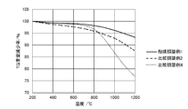
- the carbon catalyst exhibits a weight reduction rate of 12.0% by weight or less from 200 ° C. to 1200 ° C. measured in thermogravimetric analysis (hereinafter referred to as “TG”) under a nitrogen atmosphere.
- TG thermogravimetric analysis
- the carbon catalyst preferably exhibits a weight reduction rate of 11.0% by weight or less, more preferably 10.0% by weight or less, and still more preferably 9.0% by weight or less. It is particularly preferable to show not more than 8.0% by weight.
- the thermal stability of the carbon catalyst is considered to be attributable, for example, to the large bonding energy between the atoms constituting the carbon structure of the carbon catalyst. For this reason, the thermally stable carbon catalyst is also electrochemically stable. And, the electrochemically stable carbon catalyst has high durability in applications such as fuel cells. Therefore, a carbon catalyst with a small weight loss rate in TG under a nitrogen atmosphere exhibits excellent durability.
- the lower limit value of the weight reduction rate of the carbon catalyst is not particularly limited, but the weight reduction rate may be 1.0% by weight or more.
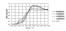
- the carbon structure of the carbon catalyst shows (a) 7130/7110 ratio 7.0 or more, (b) 7135/7110 ratio 7.0 or more in the XAFS analysis of the K absorption edge of iron, or (a) 7130/7110 ratio 7.0 or more and (b) 7135/7110 ratio 7.0 or more are shown.
- the 7130/7110 ratio and / or the 7135/7110 ratio of the carbon structure of the carbon catalyst is preferably 8.0 or more, more preferably 9.0 or more, and 10.0 or more It is even more preferable, and particularly preferably 11.0 or more.
- the upper limits of the 7130/7110 ratio and the 7135/7110 ratio of the carbon catalyst are not particularly limited, but the 7130/7110 ratio and the 7135/7110 ratio may be 30.0 or less.
- the carbon structure of the carbon catalyst exhibits a 7130/7110 ratio and / or a 7135/7110 ratio that is above the specified threshold in XAFS analysis contributes to the excellent catalytic activity of the carbon catalyst. That is, in XAFS analysis of the K absorption edge of iron, the energy of the peak after the K absorption edge indicates the energy at which the 1s orbital electron of the iron atom transitions to the antibonding orbital of the ⁇ bond, It reflects the binding energy. On the other hand, the peak before the K absorption edge indicates that the electron of the 1s orbital of iron atom is transitioning to the d orbital, which indicates that the iron atom has an asymmetric structure. There is.
- the high normalized absorbances at 7130 eV and 7135 eV indicate that the iron atom has two specific bonds exhibiting energy corresponding to 7130 eV and 7135 eV, and the high normalized absorbance at 7110 eV Indicates that the iron atom has an asymmetric structure. And in a carbon catalyst, it is thought that the iron atom which has said 2 types of nonmetallic bonds mentioned above functions as one of the active sites.
- a carbon catalyst having a carbon structure that exhibits a 7130/7110 ratio and / or a 7135/7110 ratio that is above the specified threshold in the XAFS analysis of the K absorption edge of iron is iron having the two specified nonmetallic bonds described above By containing a relatively large number of atoms, it has excellent catalytic activity.
- the carbon structure of the carbon catalyst exhibits a 7130/7110 ratio and / or a 7135/7110 ratio within the range above the specified threshold and less than or equal to 30.0 in the XAFS analysis of iron, then in the carbon catalyst, the above two particular non-metallic bonds of the iron atom and the above asymmetric structure exist in a particular balance corresponding to the range.
- the carbon catalyst has excellent catalytic activity by containing an iron atom having the above two specific nonmetal bonds and the above asymmetric structure.
- the carbon catalyst is an excellent catalyst by containing iron, exhibiting a weight reduction rate below the above-mentioned specific threshold, and including a carbon structure exhibiting a 7130/7110 ratio and / or a 7135/7110 ratio above the above specific threshold. It has activity and excellent durability.
- the carbon catalyst can be defined by arbitrarily combining each of the above-described weight reduction rate thresholds with each of the above-described 7130/7110 ratio and / or the above-described 7135/7110 ratio thresholds.
- the carbon catalyst includes, for example, a carbon structure showing the 7130/7110 ratio of 8.0 or more and / or the 7135/7110 ratio, and exhibits the weight reduction rate of 11.0% by weight or less Is more preferably including a carbon structure showing the 7130/7110 ratio of 9.0 or more and / or the 7135/7110 ratio, and showing the weight reduction rate of 10.0% by weight or less, 10.0 It is still more preferable to include the carbon structure showing the above 7130/7110 ratio and / or the above 7135/7110 ratio, and to show the above weight reduction rate of not more than 9.0% by weight, the above 7130 / 11.0 or more. It is particularly preferred to include a carbon structure exhibiting a 7110 ratio and / or the above 7135/7110 ratio, and to exhibit the above weight loss of less than or equal to 8.0% by weight.
- the carbon catalyst may have a ratio of mesopore volume to total pore volume (hereinafter referred to as “mesopore ratio”) of 20% or more.
- the mesopore ratio of the carbon catalyst is preferably 25% or more, and particularly preferably 30% or more.
- the upper limit value of the mesopore ratio of the carbon catalyst is not particularly limited, but the mesopore ratio may be, for example, 70% or less, and preferably 65% or less.
- the mesopore ratio of the carbon catalyst can be defined by arbitrarily combining the above lower limit value and the upper limit value. That is, the mesopore ratio of the carbon catalyst is, for example, preferably 20% or more and 70% or less, more preferably 25% or more and 65% or less, and particularly preferably 30% or more and 65% or less preferable.
- the mesopores are pores having a diameter of 2 nm or more and 50 nm or less, and the mesopore volume (cm 3 / g) is the total volume of the mesopores.
- the micropores are pores having a diameter of less than 2 nm, and the micropore volume (cm 3 / g) is the total volume of the micropores.
- the macropores are pores having a diameter of more than 50 nm, and the macropore volume (cm 3 / g) is the sum of the volumes of the macropores.
- total pore volume (cm 3 / g) is the sum of micropore volume, mesopore volume and macropore volume.
- the carbon catalyst may have an iron content of 0.01% by weight or more as measured by inductively coupled plasma mass spectrometry (hereinafter referred to as “ICP-MS”).
- ICP-MS inductively coupled plasma mass spectrometry
- the iron content of the carbon catalyst is particularly preferably 0.05% by weight or more.
- the iron content of the carbon catalyst by ICP-MS is calculated as the ratio (weight%) of the weight of iron atoms to the total weight of the carbon catalyst.
- the upper limit value of the iron content of the carbon catalyst is not particularly limited, but the iron content may be 10.00% by weight or less.
- the carbon catalyst may exhibit a nitrogen atom content of 1.0% by weight or more as measured by elemental analysis by a combustion method.
- the carbon catalyst preferably exhibits a nitrogen atom content of 1.1% by weight or more according to elemental analysis, and particularly preferably 1.2% by weight or more.
- the fact that the carbon catalyst shows the above-mentioned specific threshold value or more as the nitrogen atom content by the above-mentioned elemental analysis indicates that the carbon catalyst contains a relatively large amount of nitrogen atoms.
- the upper limit of the nitrogen atom content by elemental analysis of the carbon catalyst is not particularly limited, but the nitrogen atom content by elemental analysis may be 10.0% by weight or less.
- the carbon catalyst has a nitrogen atom concentration of 1.0 atm% or more measured by X-ray photoelectron spectroscopy (hereinafter referred to as “XPS”), and a nitrogen atom content of 1.0 measured by elemental analysis by a combustion method. It is also possible to indicate% by weight or more.
- XPS X-ray photoelectron spectroscopy
- the carbon catalyst preferably exhibits a nitrogen atom concentration of 1.1 atm% or more by XPS, and preferably exhibits a nitrogen atom content of 1.1% by weight or more by elemental analysis, and a nitrogen atom concentration of 1.2 atm% or more by XPS In particular, it is preferable that the nitrogen atom content by elemental analysis is 1.2% by weight or more.
- the carbon catalyst shows the nitrogen atom concentration by XPS or more at the specific threshold or more, and the nitrogen atom content by the elemental analysis shows the carbon nitride at the specific threshold or more. Not only the part up to the depth of the) but also the inside (deep than the surface part) contains nitrogen atoms of the same amount as the surface part, ie relatively homogeneous carbon from the surface part to the inside It reflects that it has a structure.
- the carbon catalyst has a relatively homogeneous carbon structure from the surface layer portion to the inside in this way, for example, even when the active point of the surface layer portion is lost, the inside is deeper than the surface layer portion.
- the function of the active site of (3) effectively suppresses the decrease in the catalytic activity of the carbon catalyst.
- the upper limit of the nitrogen atom concentration by XPS and the nitrogen atom content by elemental analysis of the carbon catalyst is not particularly limited, but the nitrogen atom concentration by XPS is 10.0 atm% or less, and the nitrogen atom by the elemental analysis The content may be 10.0% by weight or less.
- the carbon catalyst has a ratio of nitrogen atom content to carbon atom content (hereinafter referred to as "N / C ratio by elemental analysis") of at least 1.1%, as measured by elemental analysis by combustion method. Good.
- the carbon catalyst preferably exhibits an N / C ratio of 1.2% or more according to elemental analysis, more preferably 1.3% or more, and still more preferably 1.4% or more. It is particularly preferable to show .5% or more.
- the fact that the carbon catalyst shows the above-mentioned specific threshold or more as the N / C ratio by the above elemental analysis indicates that the carbon catalyst contains a relatively large amount of nitrogen atoms.
- the upper limit value of the N / C ratio by elemental analysis of the carbon catalyst is not particularly limited, but may be 15.0% or less.
- the carbon catalyst exhibits a ratio of nitrogen atom concentration to carbon atom concentration (hereinafter referred to as “N / C ratio by XPS”) of 1.1% or more measured by XPS, and elemental analysis by combustion method
- N / C ratio by XPS ratio of nitrogen atom concentration to carbon atom concentration
- the carbon catalyst show an N / C ratio of 1.2% or more by XPS and a N / C ratio of 1.2% or more by elemental analysis, and an N / C ratio of 1.3% by XPS It is more preferable to show the above, and to show an N / C ratio of 1.3% or more by elemental analysis, and to show an N / C ratio of 1.4% or more by XPS, and an N / C ratio of 1.4% by elemental analysis It is still more preferable to show the above, and it is particularly preferable to show an N / C ratio of 1.5% or more by XPS and to show an N / C ratio of 1.5% or more by elemental analysis.
- the carbon catalyst shows the N / C ratio by XPS or more as the specific threshold or more, and the N / C ratio as the element analysis shows the specific threshold or more as the N / C ratio, the carbon catalyst has a surface portion (a few nm from the surface Not only the part up to the depth of (1) but also the inside (deep inside the surface part) contains the same amount of nitrogen atoms as the surface part.
- the carbon catalyst has a relatively homogeneous carbon structure from the surface layer portion to the inside in this way, for example, even when the active point of the surface layer portion is lost, the inside is deeper than the surface layer portion.
- the function of the active site of (3) effectively suppresses the decrease in the catalytic activity of the carbon catalyst.
- the upper limit value of the N / C ratio by XPS and the N / C ratio by elemental analysis of the carbon catalyst is not particularly limited, but the N / C ratio by XPS is 15.0% or less and by the elemental analysis The N / C ratio may be 15.0% or less.
- the carbon catalyst may contain iron and a metal other than iron (hereinafter referred to as "non-ferrous metal").
- the non-ferrous metal contained in the carbon catalyst is not particularly limited as long as the above-mentioned characteristics of the carbon catalyst can be obtained, but is preferably a transition metal.
- the nonferrous metal is a metal belonging to Groups 3 to 12 of the periodic table, and preferably a transition metal belonging to the fourth period of Groups 3 to 12 of the periodic table.
- non-ferrous metals contained in the carbon catalyst include, for example, scandium (Sc), titanium (Ti), vanadium (V), chromium (Cr), manganese (Mn), cobalt (Co), nickel (Ni), Copper (Cu), zinc (Zn), yttrium (Y), zirconium (Zr), niobium (Nb), molybdenum (Mo), ruthenium (Ru), rhodium (Rh), palladium (Pd), silver (Ag), A group consisting of lanthanoids (eg one or more selected from the group consisting of neodymium (Nd), samarium (Sm) and gadolinium (Gd)) and actinoids, or Sc, Ti, V, Cr, Mn, Co, Ni, Cu
- the carbon catalyst preferably contains Fe and at least one nonferrous metal selected from the group consisting of Ti, Cr, Zn, Nd, Sm and Gd, and comprises Fe, Cr, Zn and Gd. It is more preferable to include one or more non-ferrous metals selected from the group.
- the carbon catalyst may contain, for example, Fe and Zn.
- the carbon catalyst may further contain other transition metals. That is, for example, when the carbon catalyst contains Fe and at least one first non-ferrous transition metal selected from the group consisting of Ti, Cr, Zn, Nd, Sm and Gd, Sc, Ti, V, Cr, A group consisting of Mn, Co, Ni, Cu, Y, Zr, Nb, Mo, Ru, Rh, Pd, Ag, a lanthanoid (eg, one or more selected from the group consisting of Nd, Sm and Gd) and an actinide; Or Sc, Ti, V, Cr, Mn, Co, Ni, Cu, Zn, Y, Zr, Nb, Mo, Ag, lanthanoid (for example, one or more selected from the group consisting of Nd, Sm and Gd) and It is also possible to further include a second non-ferrous transition metal which is at least one selected from the group consisting of actinides and which is different from
- the carbon catalyst may not contain platinum (Pt).
- the carbon catalyst is one selected from the group consisting of platinum (Pt), ruthenium (Ru), rhodium (Rh), palladium (Pd), iridium (Ir), gold (Au) and osmium (Os). The above may not be included.
- the carbon catalyst contains, in addition to iron, non-ferrous metal derived from the carbonization raw material described later, the carbon catalyst is caused by the fact that the carbonization raw material contains the iron and nonferrous metal.
- the inside contains the iron and the nonferrous metal. That is, even when the carbon catalyst is produced through the metal removal treatment described later, a trace amount of the iron and non-ferrous metals remain inside the carbon catalyst.
- the carbon catalyst containing iron and nonferrous metals when the carbon catalyst containing iron and nonferrous metals is in the form of particles, when the particles constituting the carbon catalyst are cut, the iron and nonferrous metals are detected in the cross section of the particles exposed by the cutting.
- the iron and non-ferrous metals contained in this carbon catalyst can be detected, for example, by inductively coupled plasma (ICP) emission spectroscopy.
- ICP inductively coupled plasma
- the carbon catalyst may have a specific surface area of 800 m 2 / g or more as measured by the BET method.
- the specific surface area of the carbon catalyst by BET method using nitrogen gas is preferably 1000 m 2 / g or more, particularly preferably 1200 m 2 / g or more.
- the specific surface area of the carbon catalyst is equal to or more than the specific threshold value contributes to the efficiency of the chemical reaction by the carbon catalyst and contributes to the excellent catalyst activity.
- the upper limit value of the specific surface area of the carbon catalyst is not particularly limited, but the specific surface area may be 3000 m 2 / g or less.
- the carbon catalyst is a carbon material which itself has catalytic activity (eg, oxygen reduction activity).
- This carbon material is a carbonized material obtained by carbonization of a raw material containing an organic substance and iron. That is, the carbon catalyst is a carbonized material of a raw material containing an organic substance and iron.
- the carbon structure of the carbon catalyst contains the nonferrous metal, but the catalytic activity of the carbon catalyst is Rather than the non-ferrous metals, it is considered to be mainly due to iron and active sites contained in the carbon structure itself.
- the carbon catalyst may be substantially free of organic compounds. That is, the content of the organic compound in the carbon catalyst may be, for example, 5% by weight or less, or 1% by weight or less.
- the Pt layer 12 may not include the specific carbon catalyst.
- the Pt layer 12 may contain a carbon catalyst other than the specific carbon catalyst described above.
- the cathode 10 may not include the layer including the specific carbon catalyst.
- the cathode 10 may include a layer including a carbon catalyst other than the specific carbon catalyst described above.
- the method for producing the carbon catalyst is not particularly limited as long as a carbon catalyst having the above-mentioned characteristics can be obtained, but in the present embodiment, a method including carbonizing a raw material containing an organic substance and iron under pressure Will be explained.
- the organic substance contained in the raw material is not particularly limited as long as it can be carbonized. That is, as the organic substance, for example, a high molecular weight organic compound (for example, a resin such as a thermosetting resin and / or a thermoplastic resin) and / or a low molecular weight organic compound are used. Alternatively, biomass may be used as the organic matter.
- a high molecular weight organic compound for example, a resin such as a thermosetting resin and / or a thermoplastic resin
- biomass may be used as the organic matter.
- a nitrogen-containing organic matter is preferably used as the organic matter.
- the nitrogen-containing organic substance is not particularly limited as long as it is an organic substance containing an organic compound containing a nitrogen atom in its molecule.
- the carbon catalyst is a carbonized raw material containing a nitrogen-containing organic substance
- the carbon structure of the carbon catalyst contains a nitrogen atom.
- organic substance for example, polyacrylonitrile, polyacrylonitrile-polyacrylic acid copolymer, polyacrylonitrile-polyacrylic acid methyl copolymer, polyacrylonitrile-polymethacrylic acid copolymer, polyacrylonitrile-polymethacrylic acid -Polymethallyl sulfonic acid copolymer, polyacrylonitrile-polymethyl methacrylate copolymer, phenol resin, polyfurfuryl alcohol, furan, furan resin, phenol formaldehyde resin, melamine, melamine resin, epoxy resin, nitrogen-containing chelate resin ( For example, one or more selected from the group consisting of polyamine type, iminodiacetic acid type, amino phosphoric acid type and aminomethylphosphonic acid type), polyamide imide resin, pyrrole, polypyrrole, polyvinylpyrrole, -Methylpolypyrrole, acrylonitrile, polyvinylidene chloride
- the content of the organic substance in the raw material is not particularly limited as long as a carbon catalyst can be obtained, but may be, for example, 5% by mass or more and 90% by mass or less, preferably 10% by mass or more and 80% by mass % Or less.
- iron contained in the carbonization raw material a single substance of the iron and / or a compound of the iron are used.
- the iron compound include one or more selected from the group consisting of iron salts, iron oxides, iron hydroxides, iron nitrides, iron sulfides, iron carbides and iron complexes. You may use it.
- the content of iron in the raw material is not particularly limited as long as a carbon catalyst can be obtained, but may be, for example, 0.001% by mass or more and 90% by mass or less, 0.002% by mass or more, It is preferable that it is 80 mass% or less.
- the carbonization raw material may further contain non-ferrous metals.
- the raw material containing the organic matter, iron and nonferrous metal is carbonized under pressure.
- the carbon catalyst is a carbonized material obtained by carbonization of a raw material containing organic matter, iron and nonferrous metal
- the carbon catalyst includes the iron and nonferrous metal.
- the non-ferrous metal contained in the raw material is not particularly limited as long as the above-described characteristics of the carbon catalyst can be obtained, but a transition metal is preferable.
- the nonferrous metal is a metal belonging to Groups 3 to 12 of the periodic table, and preferably a transition metal belonging to the fourth period of Groups 3 to 12 of the periodic table.
- nonferrous metals contained in the raw material are, for example, Sc, Ti, V, Cr, Mn, Co, Ni, Cu, Zn, Y, Zr, Nb, Mo, Ru, Rh, Pd, Ag, lanthanoids
- one or more selected from the group consisting of Nd, Sm and Gd and a group consisting of actinoids
- Sc, Ti, V, Cr, Mn, Co, Ni, Cu, Zn, Y, Zr, Nb, Mo Or Ag, a lanthanoid for example, one or more selected from the group consisting of Nd, Sm and Gd
- one or more selected from the group consisting of actinoids for example, one or more selected from the group consisting of actinoids.
- the raw material preferably contains Fe and at least one non-ferrous metal selected from the group consisting of Ti, Cr, Zn, Nd, Sm and Gd, and from the group consisting of Fe, Cr, Zn and Gd It is more preferable to include one or more non-ferrous metals to be selected.
- the raw material may contain Fe and Zn.
- the raw material may further contain other transition metals. That is, for example, when the raw material contains Fe and one or more first non-ferrous transition metals selected from the group consisting of Ti, Cr, Zn, Nd, Sm and Gd, Sc, Ti, V, Cr, Mn , Co, Ni, Cu, Zn, Y, Zr, Nb, Mo, Ru, Rh, Pd, Ag, lanthanoids (for example, one or more selected from the group consisting of Nd, Sm and Gd) and actinoids Or Sc, Ti, V, Cr, Mn, Co, Ni, Cu, Zn, Y, Zr, Nb, Mo, Ag, lanthanoid (for example, one or more selected from the group consisting of Nd, Sm and Gd) And at least one second metal selected from the group consisting of actinides, which may be different from the first non-ferrous transition metal.
- first non-ferrous transition metals selected from the group consisting of Ti, Cr, Zn, Nd, Sm and G
- the raw material may not contain platinum (Pt).
- the raw material is one or more selected from the group consisting of platinum (Pt), ruthenium (Ru), rhodium (Rh), palladium (Pd), iridium (Ir), gold (Au) and osmium (Os). May not be included.
- nonferrous metal contained in the raw material a single substance of the nonferrous metal and / or a compound of the nonferrous metal are used.
- nonferrous metal compounds include salts of nonferrous metals, oxides of nonferrous metals, hydroxides of nonferrous metals, nitrides of nonferrous metals, sulfides of nonferrous metals, carbides of nonferrous metals and complexes of nonferrous metals. One or more selected from the group may be used.
- the content of non-ferrous metals in the raw material (the total of the contents of the two or more non-ferrous metals when two or more non-ferrous metals are used) is not particularly limited as long as a carbon catalyst can be obtained. For example, it may be 1% by mass or more and 90% by mass or less, and preferably 2% by mass or more and 80% by mass or less.
- Carbonization is performed by heating a raw material under pressure and holding the raw material at a temperature at which the raw material is carbonized (hereinafter, referred to as “carbonization temperature”).
- the carbonization temperature is not particularly limited as long as the raw material is carbonized, and is, for example, 300 ° C. or more. That is, in this case, the raw material containing the organic matter is carbonized at a temperature of 300 ° C. or higher under pressure.
- the carbonization temperature may be, for example, 700 ° C. or higher, preferably 900 ° C. or higher, more preferably 1000 ° C. or higher, and particularly preferably 1100 ° C. or higher.
- the upper limit of the carbonization temperature is not particularly limited, but the carbonization temperature is, for example, 3000 ° C. or less.
- the temperature rising rate to the carbonization temperature is, for example, 0.5 ° C./min or more and 300 ° C./min or less.
- the time to hold the raw material at the carbonization temperature is, for example, 1 second or more and 24 hours or less, preferably 5 minutes or more and 24 hours or less.
- Carbonization is preferably performed in an inert gas atmosphere such as a nitrogen atmosphere. That is, carbonization is preferably performed, for example, under the flow of an inert gas such as nitrogen gas.
- the pressure of the atmosphere under which the carbonization is performed is not particularly limited as long as the pressure is higher than the atmospheric pressure, and for example, the pressure is 0.05 MPa or more in gauge pressure. That is, in this case, the raw material containing the organic matter is carbonized under a pressure of 0.05 MPa or more.
- the pressure of the atmosphere for carbonization may be 0.10 MPa or more, 0.15 MPa or more, or 0.20 MPa or more in gauge pressure.
- the method of producing a carbon catalyst may further include subjecting the carbonized material obtained by the carbonization to a further treatment. That is, for example, the carbonized material may be subjected to metal removal treatment.
- the method for producing a carbon catalyst includes carbonizing a raw material containing an organic substance under pressure, and then subjecting the carbonized material obtained by the carbonization to a metal removal treatment.
- the metal removal treatment is a treatment to reduce the amount of metal derived from the raw material contained in the carbonized material.
- the metal removal process is, for example, an acid cleaning process and / or an electrolytic process.
- Catalyst preparation example 1 1.0 g of polyacrylonitrile (PAN), 1.0 g of 2-methylimidazole, 6.0 g of zinc chloride (ZnCl 2 ) and 0.18 g of iron (III) chloride hexahydrate (FeCl 3 ⁇ 6H 2 O) was mixed with 30 g of dimethylformamide. The solvent was removed from the resulting mixture by drying. The dried mixture was heated in air to infusibilize at 250 ° C. Carbonization was carried out by heating and holding the infusibilized mixture at 1300 ° C. under a nitrogen atmosphere and a gauge pressure of 0.90 MPa.
- Diluted hydrochloric acid was added to the carbonized material obtained by carbonization and stirred.
- the suspension containing the carbonized material was then filtered using a filtration membrane and the carbonized material was washed with distilled water until the filtrate was neutral.
- the metal removal treatment was carried out by acid cleaning.
- the carbonized material after the metal removal treatment was crushed by a pulverizer until the median value of the particle diameter was 1 ⁇ m or less.
- the pulverized carbonized material was obtained as a carbon catalyst of Catalyst Preparation Example 1.
- Catalyst preparation example 2 A carbon catalyst of Catalyst Preparation Example 2 was obtained in the same manner as the above-mentioned Catalyst Preparation Example 1 except that carbonization was performed under a gauge pressure of 0.20 MPa instead of 0.90 MPa.
- Catalyst preparation example 3 Before infusibilization, a mixture further containing 0.018 g of chromium chloride hexahydrate (CrCl 3 .6H 2 O) was prepared, and the same as in Catalyst Preparation Example 1 described above except that the mixture was infusibilized. The carbon catalyst of Catalyst Preparation Example 3 was obtained.
- Catalyst preparation example 4 was prepared in the same manner as in catalyst preparation example 1 except that a mixture further containing 0.06 g of boric acid (B (HO) 3 ) was prepared before infusibilization, and the mixture was infusible. Carbon catalyst was obtained.
- B (HO) 3 boric acid
- Catalyst preparation example 5 A carbon catalyst of Catalyst Preparation Example 5 was obtained in the same manner as in the above-mentioned Catalyst Preparation Example 1 except that 2.0 g of 2-methylimidazole was used instead of 1.0 g.
- Catalyst preparation example 6 Before infusibilization, a mixture further containing 0.075 g of gadolinium nitrate hexahydrate (Gd (NO 3 ) 3 .6H 2 O) was prepared, and the catalyst was prepared as described above except that the mixture was infusibilized. In the same manner as in the above, a carbon catalyst of Catalyst Preparation Example 6 was obtained.
- Gadolinium nitrate hexahydrate Gd (NO 3 ) 3 .6H 2 O
- Diluted hydrochloric acid was added to the carbonized material obtained by carbonization and stirred.
- the suspension containing the carbonized material was then filtered using a filtration membrane and the carbonized material was washed with distilled water until the filtrate was neutral.
- the metal removal treatment by acid cleaning was performed.
- the carbonized material after the metal removal treatment was crushed by a pulverizer until the median value of the particle diameter was 1 ⁇ m or less.
- the pulverized carbonized material was obtained as a carbon catalyst of Comparative Preparation Example 1.
- Comparative Preparation Example 2 A carbon catalyst of Comparative Preparation Example 2 was obtained in the same manner as in Comparative Preparation Example 1 described above except that carbonization was performed at 1000 ° C. instead of 1300 ° C.
- Comparative Preparation Example 3 A carbon catalyst of Comparative Preparation Example 3 was obtained in the same manner as in Comparative Preparation Example 1 described above except that carbonization was performed at 800 ° C. instead of 1300 ° C.
- the obtained polyacrylonitrile particles were gradually heated from 190 ° C. and heat-treated at 230 ° C. in air for 1 hour to obtain an infusible material of polyacrylonitrile particles.
- An iron (II) chloride tetrahydrate is supported on the obtained infusibilized body so that the composition of iron atoms is 0.3% by mass, and an infusibilized form of polyacrylonitrile obtained-iron (II) chloride
- the tetrahydrate composition was heat-treated at 600 ° C. for 5 hours in a nitrogen stream, and was subjected to dispersion treatment by a ball mill.
- a particulate carbon catalyst (a carbon catalyst of Comparative Preparation Example 4) was obtained by heat treatment (activation treatment) under an ammonia stream at 800 ° C. for 1 hour and at 1000 ° C. for 1 hour under an ammonia stream.
- Thermogravimetric analysis Using a differential thermal balance (TG-DTA 2020SA, manufactured by Bruker AXS Co., Ltd.), the weight reduction rate of the carbon catalyst was measured by TG under a nitrogen atmosphere. That is, an alumina container containing 10 mg of a carbon catalyst was placed in the apparatus, and then the apparatus was held for 1 hour in a state of flowing nitrogen (200 mL / min) at normal temperature. Thereafter, the carbon catalyst was heated from normal temperature to 1200 ° C. at a temperature rising rate of 10 ° C./min, and the weight reduction rate from 200 ° C. to 1200 ° C. was measured. The difference obtained by subtracting the weight of the carbon catalyst at 1200 ° C.
- FIG. 2 shows the measurement results of the weight loss ratio of the carbon catalyst obtained in Catalyst Preparation Example 1 and Comparative Preparation Examples 2 and 4 by TG.
- the horizontal axis shows temperature (° C.)
- the vertical axis shows TG weight loss rate (%).
- a carbon catalyst the amount of which was adjusted so that the edge jump (difference in absorbance before and after the absorption edge) became 1, was packed in a cylinder and compressed, and a sample manufactured by compression was measured by the permeation method.
- the edge jump is 1 and the absorbance after the absorption edge (energy for absorbing electrons bound to the orbital of the atom to the lowest unoccupied state (absorption edge energy)) exceeds 4
- the amount of carbon catalyst was adjusted so as to maximize the edge jump within the range where the absorbance after the absorption edge does not exceed 4.
- a mixture obtained by adding boron nitride (BN) to a carbon catalyst was packed into a cylinder.
- the measurement range was 6813 eV to 8213 eV
- the step width was 0.32 eV
- the measurement time was 0.06 second / point.
- Normalization was performed by inputting the following numerical values in the “Normalization and background removal parameters” column in the “Main window” of the analysis software “Athena”.
- E 0 energy at which the first derivative of absorbance is maximum.
- Normalization order 3.
- Pre-edge range -150 to -30.
- Normalization range 150 to 1000.
- Flatten normalized data On. However, the condition was not changed from the default.
- the normalization is not particularly limited as long as the background before and after the absorption edge is drawn so as to pass through the center of the measurement data in each region.
- FIG. 3 shows the carbon catalysts obtained in Catalyst Preparation Example 1 and Comparative Preparation Examples 1, 2 and 4, and powdered ⁇ iron (iron powder, iron powder, and sum powder having an average particle diameter of 150 ⁇ m for comparison).
- Fig. 6 shows an XAFS spectrum of Mitsukohyaku Kogyo Co., Ltd.).
- the horizontal axis represents energy (eV), and the vertical axis represents normalized absorbance.
- the carbon catalyst was kept at 100 ° C. and 6.7 ⁇ 10 ⁇ 2 Pa for 3 hours to remove the water adsorbed to the carbon catalyst.
- the specific surface area (m 2 / g) of the carbon catalyst was obtained from the nitrogen adsorption isotherm at 77 K by the BET method.
- the nitrogen adsorption isotherm at 77 K was obtained by measuring the change in the amount of nitrogen adsorbed onto the carbon material as the pressure of nitrogen gas changed at a temperature of 77 K.
- the total pore volume (cm 3 / g) was obtained by the adsorption amount in Furthermore, the micropore volume (cm 3 / g) was calculated by subtracting the sum of the macropore volume and the mesopore volume from the total pore volume. Then, the value obtained by dividing the mesopore volume (cm 3 / g) by the total pore volume (cm 3 / g) was multiplied by 100 to calculate the mesopore ratio (%).
- the BJH method is a representative method for obtaining the distribution of mesopores proposed by Barrett, Joyner, Halenda (EP Barrett, LG Joyner and PP Halenda, J Am Chem Soc, 73, 373, ( 1951).
- the iron content of the carbon catalyst was measured by ICP-MS. That is, the nonmetallic component in the said carbon catalyst was removed by heat-retaining 25 mg of carbon catalysts at 800 degreeC under air
- ICP-8100 sequential type plasma emission analyzer
- the carbon catalyst was analyzed by XPS. That is, the X-ray photoelectron spectrometer (AXIS NOVA, manufactured by KRATOS) was used to measure the photoelectron spectrum from the core level of carbon atoms, nitrogen atoms and oxygen atoms on the surface of the carbon catalyst. AlK alpha ray (10 mA, 15 kV, Pass energy 40 eV) was used as an X-ray source. In the obtained photoelectron spectrum, the binding energy was corrected so that the peak top of the C1s peak derived from the 1s orbital of the carbon atom is located at 284.5 eV.
- AXIS NOVA X-ray photoelectron spectrometer
- nitrogen atom concentration (atm%), carbon atom concentration (atm%), and oxygen atom concentration (atm%) were obtained. Further, the value obtained by dividing the nitrogen atom concentration (atm%) by the carbon atom concentration (atm%) was multiplied by 100 to calculate the N / C ratio (%) by XPS.
- Elemental analysis was performed by the combustion method of the carbon catalyst. That is, the nitrogen content of the carbon catalyst was measured by the combustion method using an organic trace element analyzer (2400II, Perkin Elmer Co., Ltd.). Helium was used as a carrier gas, and 2 mg of a carbon catalyst was analyzed under the conditions of a combustion tube temperature of 980 ° C. and a reduction tube temperature of 640 ° C. Then, the value obtained by dividing the weight of the nitrogen atom contained in the carbon catalyst by the total weight of the carbon catalyst was multiplied by 100 to calculate the nitrogen atom content (% by weight) of the carbon catalyst.
- an organic trace element analyzer 2400II, Perkin Elmer Co., Ltd.
- a value obtained by dividing the weight of carbon atom and the weight of hydrogen contained in the carbon catalyst by the total weight of the carbon catalyst respectively is multiplied by 100 to obtain the carbon atom content (% by weight) and the hydrogen atom content Weight percent was calculated. Further, the value obtained by dividing the nitrogen atom content (% by weight) by the carbon atom content (% by weight) was multiplied by 100 to calculate the N / C ratio (%) by elemental analysis.
- the catalytic activity of the carbon catalyst was measured by a rotating ring disk electrode device (RRDE-3A rotating ring disk electrode device ver.1.2, manufactured by BAS Co., Ltd.) and a dual electrochemical analyzer (CHI700C, manufactured by ALS Corporation) And evaluation was carried out. That is, first, a three-pole rotating ring disk electrode device having a working electrode containing a carbon catalyst was produced.
- a platinum electrode (Pt counter electrode 23 cm, manufactured by BAS Co., Ltd.) is used as the counter electrode, and a reversible hydrogen electrode (RHE) (storage type reversible hydrogen electrode, manufactured by EC Frontier, Inc.) is used as the reference electrode.
- RHE reversible hydrogen electrode
- a rotating ring disk electrode device having a working electrode containing a carbon catalyst, a platinum electrode as a counter electrode, and a reversible hydrogen electrode (RHE) as a reference electrode was obtained.
- 0.1 M perchloric acid aqueous solution was used as electrolyte solution.
- N 2 -LSV In the case of N 2 -LSV, first, nitrogen bubbling was performed for 10 minutes to remove oxygen in the electrolyte. Thereafter, the electrode was rotated at a rotational speed of 1600 rpm, and the current density when the potential was swept at a sweeping speed of 20 mV / sec was recorded as a function of the potential.
- Example 1 A CC layer containing a carbon catalyst was prepared. That is, first, 0.25 g of the carbon catalyst prepared in Catalyst Preparation Example 1, 3.5 g of a 5% by weight solution of ionomer having an EW value of 700, and 25 g of balls are charged into a pot and ball milled at 200 rpm for 50 minutes. The slurry-like CC layer composition containing the said uniformly dispersed carbon catalyst was obtained by mixing.
- the slurry-like CC layer composition was used in a carbon catalyst content of 2 on a 5 cm 2 area of a gas diffusion layer (“29 BC”, manufactured by SGL Carbon Co., Ltd.) (2.3 cm ⁇ 2.3 cm).
- a gas diffusion layer (“29 BC”, manufactured by SGL Carbon Co., Ltd.) (2.3 cm ⁇ 2.3 cm).
- a CC layer containing a carbon catalyst and having an electrolyte material ratio of 0.7 was formed on the gas diffusion layer.
- Pt / C platinum-supported carbon
- Pt / C platinum-supported carbon
- a platinum-containing catalyst (UNPC 40-II, manufactured by Ishifuku Metal Industry Co., Ltd.)
- Pt / C platinum-supported carbon
- ionomer having an EW value of 700
- 2.5 g of distilled water platinum particles supported on the carbon support
- 25 g of balls By uniformly charging .25 g, 3.5 g of a 5 wt% solution of ionomer having an EW value of 700, 2.5 g of distilled water, and 25 g of balls into a pot and mixing in a ball mill at 200 rpm for 50 minutes, uniform A slurry-like Pt layer composition containing the dispersed Pt / C and an electrolyte material ratio of 0.7 was obtained.
- the obtained slurry-like Pt layer composition was added to platinum in a 5 cm 2 area of a solid polymer electrolyte membrane (NAFION (registered trademark) 211, manufactured by Dupont) (2.3 cm ⁇ 2.3 cm).
- NAFION registered trademark
- a Pt layer containing platinum and having an electrolyte material ratio of 0.7 was formed on the solid polymer electrolyte membrane.
- Pt / C that whose ratio of the weight of platinum contained in the said Pt / C with respect to the weight of the said Pt / C is 40 weight% was used.
- the content of platinum in the Pt layer was calculated by dividing the weight of platinum contained in Pt / C in the Pt layer by the area of the Pt layer.
- the area of the CC layer and the area of the Pt layer were both 5 cm 2 , so the area of the catalyst layer of the cathode composed of the CC layer and the Pt layer was also 5 cm 2 .
- anode was produced. That is, 0.5 g of Pt / C, 10 g of 5 wt% NAFION (registered trademark) solution (Aldrich), 2 g of distilled water, and 25 g of balls are put into a pot and mixed in a ball mill at 200 rpm for 50 minutes. Thus, a slurry-like anode composition was prepared. The slurry-like anode composition is applied onto the area of 5 cm 2 of the gas diffusion layer so that the content of Pt / C is 0.3 mg / cm 2 and dried, thereby the gas diffusion layer An anode was formed on top of which was a catalyst layer containing Pt / C.
- NAFION registered trademark
- An MEA including the other, the gas diffusion layer, and an anode disposed between the solid polymer electrolyte membrane, and a single cell including the MEA were manufactured.
- the MEA by pressure bonding the solid polymer membrane between a pair of gas diffusion layers under the conditions of 150 ° C. and 1 MPa so that the anode formed on the other gas diffusion layer is in contact with the MEA. Made. Then, a pair of gaskets were attached to the MEA so as to sandwich the MEA, and a pair of separators was sandwiched between the pair of gaskets to form a unit cell of a fuel cell.
- the unit cell produced as mentioned above was installed in fuel cell automatic evaluation system (made by Toyo Technica Co., Ltd.), and the power generation test was done.
- the power generation test first, the relative humidity 50% air (oxygen) is supplied at 2.0 L / min to the cathode with a back pressure of 20 kPa to the single cell, and the relative humidity 50% hydrogen is applied at 0.2 L / min to the anode
- the open circuit voltage was measured for 5 minutes with a supply and cell temperature set at 55 ° C. Thereafter, while changing the cell current density from 1.5 A / cm 2 to 0 A / cm 2 , each current density was held for 3 minutes to measure the cell voltage at each current density.
- a potential (mV) observed at a current density of 0.2 A / cm 2 was recorded as an initial potential BOL (Beginning Of Life) as one of the indicators showing the catalyst activity at the start of the durability test. .
- the poisoning test was then performed. That is, first, 50% relative humidity 50% air (oxygen) is supplied to the cathode with a back pressure of 20 kPa to the single cell at 2.0 L / min, and 50% relative humidity hydrogen is supplied to the anode at 0.2 L / min, The cell temperature was set to 55 ° C., and the current density 0.3 A / cm 2 was maintained for 30 minutes.
- dry air (oxygen) containing 10 ppm sulfur dioxide is supplied to the cathode at a back pressure of 20 kPa at 0.2 L / min
- hydrogen at 50% relative humidity is supplied to the anode at 0.2 L / min
- the cell temperature is 55 °C is set to and held at a current density of 0.3 a / cm 2 90 min.
- the relative humidity 50% air (oxygen) is supplied at 2.0 L / min to the cathode with back pressure 20 kPa
- the relative humidity 50% hydrogen is supplied at 0.2 L / min to the anode
- the cell temperature is set to 55 ° C.
- the current density of 0.3 A / cm 2 was maintained for 30 minutes.
- a current holding test (durability test) was performed. That is, for the unit cell, saturated humidified air (oxygen) is supplied at 2.0 L / min to the cathode with a back pressure of 70 kPa, saturated humidified hydrogen is supplied at 0.5 L / min to the anode, and the cell temperature is 75 ° C. The current density was kept constant at 0.5 A / cm 2 , and this state was kept for 100 hours.
- Example 2 A cathode, an MEA, and a unit cell were produced in the same manner as in Example 1 except that the platinum content in the Pt layer was changed to 0.020 mg / cm 2 , and a power generation test, a poisoning test, and a durability test were performed.
- Example 3 A cathode, an MEA, and a unit cell were produced in the same manner as in Example 1 except that the content of platinum in the Pt layer was 0.005 mg / cm 2 , and a power generation test, a poisoning test, and a durability test were performed.
- Example 4 A cathode, an MEA, and a single cell were produced in the same manner as in Example 1 except that the content of platinum in the Pt layer was changed to 0.100 mg / cm 2 , and a power generation test, a poisoning test, and a durability test were performed.
- Example 5 A cathode, MEA, and single cell were prepared in the same manner as in Example 1 except that the content of the carbon catalyst in the CC layer was 1.0 mg / cm 2 , and a power generation test, a poisoning test, and a durability test were performed. .
- Example 6 The cathode, MEA and unit cell were prepared in the same manner as in Example 1 except that the content of the carbon catalyst in the CC layer was 1.0 mg / cm 2 and the content of platinum in the Pt layer was 0.020 mg / cm 2. Power generation test, poisoning test, and durability test.
- Example 7 A cathode, an MEA, and a single cell were prepared in the same manner as in Example 1 except that the content of the carbon catalyst in the CC layer was 1.0 mg / cm 2 and the content of platinum in the Pt layer was 0.005 mg / cm 2. Power generation test, poisoning test, and durability test.
- Example 8 The cathode, MEA and single cell were prepared in the same manner as in Example 1 except that the content of the carbon catalyst in the CC layer was 6.0 mg / cm 2, and the power generation test, the poisoning test, and the durability test were performed. .
- Example 9 A cathode, an MEA, and a single cell were produced in the same manner as in Example 1 except that the electrolyte material ratio of the CC layer was set to 0.9, and a power generation test, a poisoning test, and a durability test were performed.
- Example 10 A cathode, an MEA, and a single cell are prepared in the same manner as in Example 1 except that the electrolyte material ratio of the CC layer is 0.9 and the content of platinum in the Pt layer is 0.020 mg / cm 2 . Poisoning test and durability test were conducted.
- Example 11 A cathode, an MEA, and a single cell were produced in the same manner as in Example 1 except that the electrolyte material ratio of the Pt layer was set to 0.5, and the power generation test, the poisoning test, and the durability test were performed.
- Example 12 A cathode, an MEA, and a single cell are prepared in the same manner as in Example 1 except that the electrolyte material ratio of the Pt layer is 0.5 and the content of platinum in the Pt layer is 0.020 mg / cm 2 . Poisoning test and durability test were conducted.
- Example 13 A cathode, an MEA, and a single cell were produced in the same manner as in Example 1 except that the electrolyte material ratio of the Pt layer was 0.2, and the power generation test, the poisoning test, and the durability test were performed.
- Example 14 A cathode, an MEA, and a single cell are prepared in the same manner as in Example 1 except that the electrolyte material ratio of the Pt layer is 0.2 and the content of platinum in the Pt layer is 0.020 mg / cm 2 , a power generation test, Poisoning test and durability test were conducted.
- Example 15 A cathode, an MEA and a single cell were prepared as in Example 1 except that the carbon catalyst prepared in Catalyst Preparation Example 2 was used as a carbon catalyst, and a power generation test, a poisoning test, and a durability test were conducted. .
- Example 16 A cathode, an MEA and a single cell were prepared as in Example 1 except that the carbon catalyst prepared in Catalyst Preparation Example 3 was used as a carbon catalyst, and a power generation test, a poisoning test, and a durability test were conducted. .
- Example 17 A cathode, an MEA and a single cell were prepared as in Example 1 except that the carbon catalyst prepared in Catalyst Preparation Example 4 was used as a carbon catalyst, and a power generation test, a poisoning test, and a durability test were conducted. .
- Example 18 A cathode, an MEA and a single cell were prepared as in Example 1 except that the carbon catalyst prepared in Catalyst Preparation Example 5 was used as a carbon catalyst, and a power generation test, a poisoning test, and a durability test were conducted. .
- Example 19 A cathode, an MEA and a single cell were prepared as in Example 1 except that the carbon catalyst prepared in Catalyst Preparation Example 6 was used as a carbon catalyst, and a power generation test, a poisoning test, and a durability test were conducted. .
- Example 20 Example of Example except using the thing (UNPC20-II, Ishifuku Metal Industry Co., Ltd. product) whose ratio of the weight of platinum contained in the said Pt / C to the weight of the said Pt / C is 20 weight% as Pt / C Similar to 1, the cathode, MEA and single cell were prepared and subjected to the power generation test, the poisoning test and the durability test.
- Example 21 A cathode, an MEA, and a single cell were prepared in the same manner as in Example 1 except that the electrolyte material ratio of the Pt layer was set to 1.2, and the power generation test, the poisoning test, and the durability test were performed.
- Example 22 A cathode, an MEA, and a single cell were produced in the same manner as in Example 1 except that the electrolyte material ratio of the Pt layer was set to 0.1, and the power generation test, the poisoning test, and the durability test were performed.
- Example 23 A cathode, an MEA, and a single cell were produced in the same manner as in Example 1 except that the electrolyte material ratio of the CC layer was set to 0.5, and a power generation test, a poisoning test, and a durability test were performed.
- Comparative Example 1 A cathode, an MEA, and a unit cell were produced in the same manner as in Example 1 except that the platinum content in the Pt layer was changed to 0.200 mg / cm 2 , and a power generation test, a poisoning test, and a durability test were performed.
- Comparative Example 2 A cathode, an MEA, and a single cell were produced in the same manner as in Example 1 except that the content of platinum in the Pt layer was changed to 0.001 mg / cm 2 , and a power generation test, a poisoning test, and a durability test were performed.
- Comparative Example 3 A cathode, an MEA and a unit cell were prepared in the same manner as in Example 1 except that the content of platinum in the Pt layer was 0.001 mg / cm 2 and the content of the carbon catalyst in the CC layer was 1.0 mg / cm 2. Power generation test, poisoning test, and durability test.
- Comparative Example 4 The cathode, MEA and single cell were prepared in the same manner as in Example 1 except that the Pt layer was not prepared (the cathode did not contain the Pt layer), and the power generation test, the poisoning test, and the durability test were conducted. .
- Comparative Example 5 A cathode, an MEA, and a single cell were prepared in the same manner as in Example 1 except that the Pt layer was not prepared (the cathode did not contain the Pt layer) and the content of the carbon catalyst in the CC layer was 1.0 mg / cm 2. Power generation test, poisoning test, and durability test.
- Comparative Example 6 A cathode, an MEA, and a single cell were prepared in the same manner as in Example 1 except that the CC layer was not prepared (the cathode did not contain the CC layer) and the platinum content in the Pt layer was 0.100 mg / cm 2. Power generation test, poisoning test, and durability test.
- Comparative Example 7 The cathode, MEA and single cell were prepared in the same manner as in Example 1 except that the CC layer was not prepared (the cathode did not contain the CC layer), and the power generation test, the poisoning test and the durability test were conducted. .
- Comparative Example 8 A cathode, an MEA, and a single cell were prepared in the same manner as in Example 1 except that the CC layer was not prepared (the cathode did not contain the CC layer) and the platinum content in the Pt layer was 0.020 mg / cm 2. Power generation test, poisoning test, and durability test.
- Comparative Example 9 The cathode, MEA and single cell were prepared in the same manner as in Example 1 except that the content of the carbon catalyst in the CC layer was 10.0 mg / cm 2, and the power generation test, the poisoning test, and the durability test were performed. .
- Comparative Example 10 A cathode, an MEA, and a unit cell were prepared in the same manner as in Example 1 except that the content of the carbon catalyst in the CC layer was 10.0 mg / cm 2 and the content of platinum in the Pt layer was 0.020 mg / cm 2. Power generation test, poisoning test, and durability test.
- Comparative Example 11 A cathode, MEA, and single cell were prepared in the same manner as in Example 1 except that the content of the carbon catalyst in the CC layer was 0.2 mg / cm 2 , and a power generation test, a poisoning test, and a durability test were performed. .
- Comparative Example 12 A cathode, an MEA and a unit cell were prepared in the same manner as in Example 1 except that the content of the carbon catalyst in the CC layer was 0.2 mg / cm 2 and the content of platinum in the Pt layer was 0.020 mg / cm 2. Power generation test, poisoning test, and durability test.
- Comparative Example 13 A cathode, an MEA, and a single cell were prepared as in Example 1 except that the carbon catalyst prepared in Comparative Preparation Example 1 was used as a carbon catalyst, and a power generation test, a poisoning test, and a durability test were performed. .
- Comparative Example 14 A cathode, an MEA and a unit cell were produced as in Example 1 except that the carbon catalyst produced in Comparative Preparation Example 2 was used as a carbon catalyst, and a power generation test, a poisoning test, and a durability test were conducted. .
- Comparative Example 15 A cathode, an MEA, and a single cell were prepared as in Example 1 except that the carbon catalyst prepared in Comparative Preparation Example 3 was used as a carbon catalyst, and a power generation test, a poisoning test, and a durability test were performed. .
- Comparative Example 16 A cathode, an MEA and a unit cell were produced as in Example 1 except that the carbon catalyst produced in Comparative Preparation Example 4 was used as a carbon catalyst, and a power generation test, a poisoning test, and a durability test were conducted. .
- FIG. 4B shows the BET specific surface area (m 2 / g), micropore volume (cm 3 / g), and mesopores of the carbon catalysts obtained in Catalyst Preparation Examples 1 to 6 and Comparative Preparation Examples 1 to 4.
- the weight loss ratio by TG of the comparative preparation examples 2, 3, 4 by TG was 12.5 weight% or more.
- the 7130/7110 ratio and the 7135/7110 ratio by XAFS of the carbon catalyst of Comparative Preparation Example 1 were 6.4 or less.
- the current density i 0.7 indicating the oxygen reduction activity of the carbon catalyst of Comparative Preparation Example 2 was ⁇ 2.0 mA / cm 2 , but that of the carbon catalyst of Comparative Preparation Examples 1, 3 and 4 was ⁇ It was only 0.1mA / cm 2 ⁇ -0.9mA / cm 2.
- the carbon catalysts of Catalyst Preparation Examples 1 to 6 have a weight reduction rate by TG of 7.3% by weight or less, and the 7130/7110 ratio and 7135/7110 ratio by XAFS are all 13.8 or more. Met. Then, the current density i 0.7 indicating the oxygen reduction activity of the carbon catalyst of Catalyst Preparation Examples 1 to 6 reached -1.2 mA / cm 2 to -1.4 mA / cm 2 .
- BET specific surface area of the carbon catalyst of Catalyst Preparation Examples 1 to 6 are 1440m 2 / g or more, the micropore volume was 0.40cm 3 /g ⁇ 0.52cm 3 / g, mesopore volume was 0.26cm 3 /g ⁇ 0.50cm 3 / g, the macropore volume was 0.01cm 3 /g ⁇ 0.02cm 3 / g, mesopores ratio, a 36% or more.
- the iron content by ICP-MS of the carbon catalysts of Catalyst Preparation Examples 1 to 6 was 0.21% by weight to 0.30% by weight.
- the carbon atom concentration by XPS of the carbon catalyst of Catalyst Preparation Examples 1 to 6 is 84.75 atm% to 90.74 atm%, the oxygen atom concentration is 7.24 atm% to 13.65 atm%, and the nitrogen atom concentration is 1.
- the ratio was 42 atm% to 1.91 atm%, and the N / C ratio was 1.60% to 2.14%.
- the oxygen atom concentration of the carbon catalysts of Catalyst Preparation Examples 1 to 6 by XPS was higher than that of the carbon catalysts of Comparative Preparation Examples 1 to 4 (3.01 atm% to 5.85 atm%).
- the nitrogen atom content by elemental analysis of the carbon catalysts of Catalyst Preparation Examples 1 to 6 is 87.30 wt% to 98.62 wt%, and the hydrogen atom content is 0.43 wt% to 1.74 wt%
- the nitrogen atom content was 1.47 wt% to 1.98 wt%, and the N / C ratio was 1.58% to 2.18%.
- FIG. 5 shows the conditions for the carbon catalyst contained in the CC layer, the conditions for platinum contained in the Pt layer, and the cells containing the cathode for the cathodes manufactured in Examples 1 to 23 and Comparative Examples 1 to 16. The results of the power generation test and the durability test are shown.
- the CC layer the content of the carbon catalyst is 1.0mg / cm 2 ⁇ 6.0mg / cm 2, the content of platinum 0.005mg / cm 2 ⁇ 0.100mg / cm 2
- an initial potential (BOL) of 700.2 mV to 760.6 mV is achieved, and durability including subsequent poisoning tests is achieved.
- the voltage drop (BOL-EOL) in the test was reduced to 27.4 mV to 58.0 mV. That is, in Examples 1 to 23, in addition to the achievement of the high initial potential, remarkably excellent durability was achieved.
- Comparative Example platinum content of Pt layer was 0.200 mg / cm 2 1
- comparative platinum content of Pt layer was 0.001 mg / cm 2 Examples 2 and 3
- Comparative Examples 11 and 12 in which the carbon catalyst content of the layer was 0.2 mg / cm 2 and Comparative Examples 13 to 16 using the carbon catalysts of Comparative Preparation Examples 1 to 4
- the initial potential (BOL) of the power generation test Were 446.8 mV to 716.4 mV
- the potential drop (BOL-EOL) in the endurance test was 66.9 mV to 251.5 mV. That is, the durability shown in Comparative Examples 1 to 16 was lower than that of Examples 1 to 23, and a high initial potential was not necessarily achieved.
- the cathode, MEA and battery according to the present invention have excellent durability. Further, as described above, since the durability test was conducted following the poisoning test, it was confirmed that the cathode, MEA and battery according to the present invention also have excellent resistance to poisoning. Furthermore, from the results of the power generation test, it was confirmed that the cathode, MEA and battery according to the present invention also have excellent power generation performance.
Landscapes
- Chemical & Material Sciences (AREA)
- General Chemical & Material Sciences (AREA)
- Electrochemistry (AREA)
- Chemical Kinetics & Catalysis (AREA)
- Engineering & Computer Science (AREA)
- Materials Engineering (AREA)
- Sustainable Energy (AREA)
- Sustainable Development (AREA)
- Manufacturing & Machinery (AREA)
- Life Sciences & Earth Sciences (AREA)
- Composite Materials (AREA)
- Inert Electrodes (AREA)
- Catalysts (AREA)
- Fuel Cell (AREA)
Priority Applications (9)
| Application Number | Priority Date | Filing Date | Title |
|---|---|---|---|
| PCT/JP2017/041282 WO2019097631A1 (ja) | 2017-11-16 | 2017-11-16 | カソード、膜電極接合体及び電池 |
| US16/761,351 US11387465B2 (en) | 2017-11-16 | 2017-11-16 | Cathode, membrane electrode assembly, and battery |
| JP2019520172A JP6835961B2 (ja) | 2017-11-16 | 2017-11-16 | カソード、膜電極接合体及び電池 |
| EP17932391.0A EP3712995A4 (en) | 2017-11-16 | 2017-11-16 | CATHODE, MEMBRANE-ELECTRODES AND BATTERY ASSEMBLY |
| CN201780096882.8A CN112106242B (zh) | 2017-11-16 | 2017-11-16 | 正极、膜电极组件和电池 |
| CN202210978684.7A CN115207379A (zh) | 2017-11-16 | 2017-11-16 | 正极、膜电极组件和电池 |
| KR1020207014054A KR102455117B1 (ko) | 2017-11-16 | 2017-11-16 | 캐소드, 막전극 접합체 및 전지 |
| CA3081959A CA3081959C (en) | 2017-11-16 | Cathode, membrane electrode assembly, and battery | |
| US17/829,878 US11764366B2 (en) | 2017-11-16 | 2022-06-01 | Cathode, membrane electrode assembly, and battery |
Applications Claiming Priority (1)
| Application Number | Priority Date | Filing Date | Title |
|---|---|---|---|
| PCT/JP2017/041282 WO2019097631A1 (ja) | 2017-11-16 | 2017-11-16 | カソード、膜電極接合体及び電池 |
Related Child Applications (2)
| Application Number | Title | Priority Date | Filing Date |
|---|---|---|---|
| US16/761,351 A-371-Of-International US11387465B2 (en) | 2017-11-16 | 2017-11-16 | Cathode, membrane electrode assembly, and battery |
| US17/829,878 Continuation US11764366B2 (en) | 2017-11-16 | 2022-06-01 | Cathode, membrane electrode assembly, and battery |
Publications (1)
| Publication Number | Publication Date |
|---|---|
| WO2019097631A1 true WO2019097631A1 (ja) | 2019-05-23 |
Family
ID=66539444
Family Applications (1)
| Application Number | Title | Priority Date | Filing Date |
|---|---|---|---|
| PCT/JP2017/041282 Ceased WO2019097631A1 (ja) | 2017-11-16 | 2017-11-16 | カソード、膜電極接合体及び電池 |
Country Status (6)
| Country | Link |
|---|---|
| US (2) | US11387465B2 (ko) |
| EP (1) | EP3712995A4 (ko) |
| JP (1) | JP6835961B2 (ko) |
| KR (1) | KR102455117B1 (ko) |
| CN (2) | CN115207379A (ko) |
| WO (1) | WO2019097631A1 (ko) |
Cited By (2)
| Publication number | Priority date | Publication date | Assignee | Title |
|---|---|---|---|---|
| EP3653294A4 (en) * | 2017-07-13 | 2021-04-14 | Nisshinbo Holdings Inc. | CARBON CATALYST, CELL ELECTRODE AND CELL |
| WO2021117369A1 (ja) * | 2019-12-12 | 2021-06-17 | パナソニックIpマネジメント株式会社 | 燃料電池用の電極触媒、燃料電池の電極触媒層、膜/電極接合体および燃料電池 |
Families Citing this family (3)
| Publication number | Priority date | Publication date | Assignee | Title |
|---|---|---|---|---|
| US12237515B2 (en) | 2021-10-22 | 2025-02-25 | Textron Innovations Inc. | Fuel cell metallic gas diffusion layer |
| CN114784304B (zh) * | 2022-04-21 | 2024-04-02 | 佛山仙湖实验室 | 双金属原子掺杂多孔碳材料催化剂及其制备方法和应用 |
| KR102822977B1 (ko) * | 2022-12-26 | 2025-06-19 | 엘티메탈 주식회사 | 연료전지용 백금촉매의 일산화탄소 내피독성 평가방법 |
Citations (5)
| Publication number | Priority date | Publication date | Assignee | Title |
|---|---|---|---|---|
| JP2012101155A (ja) * | 2010-11-08 | 2012-05-31 | Gunma Univ | 炭素触媒及びその製造方法並びにこれを用いた電極及び電池 |
| JP2016015283A (ja) | 2014-07-03 | 2016-01-28 | 帝人株式会社 | カソード電極構造体及び膜・電極接合体 |
| JP2016032802A (ja) * | 2014-07-31 | 2016-03-10 | 旭化成ケミカルズ株式会社 | 炭素触媒及びその製造方法 |
| JP2016207575A (ja) | 2015-04-27 | 2016-12-08 | ダイハツ工業株式会社 | 燃料電池 |
| WO2017199653A1 (ja) * | 2016-05-17 | 2017-11-23 | 日清紡ホールディングス株式会社 | 電池電極、電池電極触媒層用組成物及び電池 |
Family Cites Families (9)
| Publication number | Priority date | Publication date | Assignee | Title |
|---|---|---|---|---|
| US6277513B1 (en) | 1999-04-12 | 2001-08-21 | General Motors Corporation | Layered electrode for electrochemical cells |
| JP4228911B2 (ja) * | 2003-12-25 | 2009-02-25 | パナソニック株式会社 | 燃料電池とその製造方法 |
| KR100671494B1 (ko) * | 2005-01-27 | 2007-01-19 | 한국과학기술연구원 | 연료전지용 다층 전극 및 그 제조 방법 |
| KR100999289B1 (ko) * | 2007-07-20 | 2010-12-07 | 주식회사 엘지화학 | 복층 촉매층을 포함하는 고분자 전해질형 연료전지용 전극및 그 제조방법 |
| US20090074956A1 (en) * | 2007-09-13 | 2009-03-19 | The Regents Of University Of Michigan | Inkjet printing of materials for use in fuel cells |
| JP5805924B2 (ja) * | 2009-08-06 | 2015-11-10 | 日産自動車株式会社 | 電解質膜−電極接合体 |
| US8916296B2 (en) * | 2010-03-12 | 2014-12-23 | Energ2 Technologies, Inc. | Mesoporous carbon materials comprising bifunctional catalysts |
| EP2871154A4 (en) | 2012-07-06 | 2015-12-23 | Panasonic Ip Man Co Ltd | CARBON BASED MATERIAL, ELECTRODE CATALYST, ELECTRODE, GAS DIFFUSION ELECTRODE, ELECTROCHEMICAL DEVICE, FUEL BATTERY AND METHOD FOR PRODUCING CARBON BASED MATERIAL |
| CN103072973B (zh) * | 2013-03-04 | 2014-06-11 | 兰州理工大学 | 氮掺杂有序介孔碳材料的制备方法 |
-
2017
- 2017-11-16 US US16/761,351 patent/US11387465B2/en active Active
- 2017-11-16 JP JP2019520172A patent/JP6835961B2/ja active Active
- 2017-11-16 EP EP17932391.0A patent/EP3712995A4/en active Pending
- 2017-11-16 WO PCT/JP2017/041282 patent/WO2019097631A1/ja not_active Ceased
- 2017-11-16 CN CN202210978684.7A patent/CN115207379A/zh active Pending
- 2017-11-16 KR KR1020207014054A patent/KR102455117B1/ko active Active
- 2017-11-16 CN CN201780096882.8A patent/CN112106242B/zh active Active
-
2022
- 2022-06-01 US US17/829,878 patent/US11764366B2/en active Active
Patent Citations (5)
| Publication number | Priority date | Publication date | Assignee | Title |
|---|---|---|---|---|
| JP2012101155A (ja) * | 2010-11-08 | 2012-05-31 | Gunma Univ | 炭素触媒及びその製造方法並びにこれを用いた電極及び電池 |
| JP2016015283A (ja) | 2014-07-03 | 2016-01-28 | 帝人株式会社 | カソード電極構造体及び膜・電極接合体 |
| JP2016032802A (ja) * | 2014-07-31 | 2016-03-10 | 旭化成ケミカルズ株式会社 | 炭素触媒及びその製造方法 |
| JP2016207575A (ja) | 2015-04-27 | 2016-12-08 | ダイハツ工業株式会社 | 燃料電池 |
| WO2017199653A1 (ja) * | 2016-05-17 | 2017-11-23 | 日清紡ホールディングス株式会社 | 電池電極、電池電極触媒層用組成物及び電池 |
Non-Patent Citations (1)
| Title |
|---|
| E P BARRETTL G JOYNERP P HALENDA, J AM CHEM SOC, vol. 73, 1951, pages 373 |
Cited By (4)
| Publication number | Priority date | Publication date | Assignee | Title |
|---|---|---|---|---|
| EP3653294A4 (en) * | 2017-07-13 | 2021-04-14 | Nisshinbo Holdings Inc. | CARBON CATALYST, CELL ELECTRODE AND CELL |
| US11145876B2 (en) | 2017-07-13 | 2021-10-12 | Nisshinbo Holdings Inc. | Carbon catalyst, cell electrode, and cell |
| WO2021117369A1 (ja) * | 2019-12-12 | 2021-06-17 | パナソニックIpマネジメント株式会社 | 燃料電池用の電極触媒、燃料電池の電極触媒層、膜/電極接合体および燃料電池 |
| JP6931808B1 (ja) * | 2019-12-12 | 2021-09-08 | パナソニックIpマネジメント株式会社 | 燃料電池用の電極触媒、燃料電池の電極触媒層、膜/電極接合体および燃料電池 |
Also Published As
| Publication number | Publication date |
|---|---|
| JPWO2019097631A1 (ja) | 2019-12-12 |
| EP3712995A4 (en) | 2021-06-16 |
| JP6835961B2 (ja) | 2021-02-24 |
| KR102455117B1 (ko) | 2022-10-14 |
| US11387465B2 (en) | 2022-07-12 |
| US20220293968A1 (en) | 2022-09-15 |
| EP3712995A1 (en) | 2020-09-23 |
| CN112106242A (zh) | 2020-12-18 |
| US11764366B2 (en) | 2023-09-19 |
| US20210175515A1 (en) | 2021-06-10 |
| CN112106242B (zh) | 2022-09-06 |
| CA3081959A1 (en) | 2019-05-23 |
| CN115207379A (zh) | 2022-10-18 |
| KR20200087158A (ko) | 2020-07-20 |
Similar Documents
| Publication | Publication Date | Title |
|---|---|---|
| US8569207B2 (en) | Carbon catalyst, method of producing same, and electrode and battery each utilizing same | |
| JP5149364B2 (ja) | 炭素触媒及びその製造方法並びにこれを用いた電極及び電池 | |
| US11764366B2 (en) | Cathode, membrane electrode assembly, and battery | |
| US12362365B2 (en) | Metal-supported catalyst, battery electrode, and battery | |
| US12249722B2 (en) | Metal-loaded catalyst, battery electrode and battery | |
| JP6553832B2 (ja) | 炭素触媒、電池電極及び電池 | |
| US11014074B2 (en) | Cell electrode, composition for cell electrode catalyst layer, and cell | |
| WO2022054486A1 (ja) | 金属担持触媒、電池電極及び電池 | |
| WO2022054485A1 (ja) | 金属担持触媒、電池電極及び電池 | |
| JP7657169B2 (ja) | 炭素担体並びにこれを含む金属担持触媒、電極及び電池 | |
| JP6630457B2 (ja) | カソード、膜電極接合体及び電池 | |
| CA3081959C (en) | Cathode, membrane electrode assembly, and battery | |
| CA3069376C (en) | Carbon catalyst, cell electrode, and cell | |
| WO2026034241A1 (ja) | 炭素担体、金属担持触媒、電極及び電池 |
Legal Events
| Date | Code | Title | Description |
|---|---|---|---|
| ENP | Entry into the national phase |
Ref document number: 2019520172 Country of ref document: JP Kind code of ref document: A |
|
| 121 | Ep: the epo has been informed by wipo that ep was designated in this application |
Ref document number: 17932391 Country of ref document: EP Kind code of ref document: A1 |
|
| ENP | Entry into the national phase |
Ref document number: 3081959 Country of ref document: CA |
|
| ENP | Entry into the national phase |
Ref document number: 20207014054 Country of ref document: KR Kind code of ref document: A |
|
| NENP | Non-entry into the national phase |
Ref country code: DE |
|
| ENP | Entry into the national phase |
Ref document number: 2017932391 Country of ref document: EP Effective date: 20200616 |