WO2019097678A1 - Élément cylindrique en fonte et structure composite - Google Patents
Élément cylindrique en fonte et structure composite Download PDFInfo
- Publication number
- WO2019097678A1 WO2019097678A1 PCT/JP2017/041498 JP2017041498W WO2019097678A1 WO 2019097678 A1 WO2019097678 A1 WO 2019097678A1 JP 2017041498 W JP2017041498 W JP 2017041498W WO 2019097678 A1 WO2019097678 A1 WO 2019097678A1
- Authority
- WO
- WIPO (PCT)
- Prior art keywords
- outer peripheral
- cylindrical member
- peripheral surface
- cast iron
- protrusion
- Prior art date
- Legal status (The legal status is an assumption and is not a legal conclusion. Google has not performed a legal analysis and makes no representation as to the accuracy of the status listed.)
- Ceased
Links
Images










Classifications
-
- B—PERFORMING OPERATIONS; TRANSPORTING
- B22—CASTING; POWDER METALLURGY
- B22D—CASTING OF METALS; CASTING OF OTHER SUBSTANCES BY THE SAME PROCESSES OR DEVICES
- B22D19/00—Casting in, on, or around objects which form part of the product
- B22D19/0009—Cylinders, pistons
-
- B—PERFORMING OPERATIONS; TRANSPORTING
- B22—CASTING; POWDER METALLURGY
- B22D—CASTING OF METALS; CASTING OF OTHER SUBSTANCES BY THE SAME PROCESSES OR DEVICES
- B22D19/00—Casting in, on, or around objects which form part of the product
- B22D19/08—Casting in, on, or around objects which form part of the product for building-up linings or coverings, e.g. of anti-frictional metal
-
- F—MECHANICAL ENGINEERING; LIGHTING; HEATING; WEAPONS; BLASTING
- F02—COMBUSTION ENGINES; HOT-GAS OR COMBUSTION-PRODUCT ENGINE PLANTS
- F02F—CYLINDERS, PISTONS OR CASINGS, FOR COMBUSTION ENGINES; ARRANGEMENTS OF SEALINGS IN COMBUSTION ENGINES
- F02F1/00—Cylinders; Cylinder heads
- F02F1/004—Cylinder liners
-
- F—MECHANICAL ENGINEERING; LIGHTING; HEATING; WEAPONS; BLASTING
- F02—COMBUSTION ENGINES; HOT-GAS OR COMBUSTION-PRODUCT ENGINE PLANTS
- F02F—CYLINDERS, PISTONS OR CASINGS, FOR COMBUSTION ENGINES; ARRANGEMENTS OF SEALINGS IN COMBUSTION ENGINES
- F02F2200/00—Manufacturing
- F02F2200/06—Casting
-
- F—MECHANICAL ENGINEERING; LIGHTING; HEATING; WEAPONS; BLASTING
- F16—ENGINEERING ELEMENTS AND UNITS; GENERAL MEASURES FOR PRODUCING AND MAINTAINING EFFECTIVE FUNCTIONING OF MACHINES OR INSTALLATIONS; THERMAL INSULATION IN GENERAL
- F16D—COUPLINGS FOR TRANSMITTING ROTATION; CLUTCHES; BRAKES
- F16D65/00—Parts or details
- F16D65/02—Braking members; Mounting thereof
- F16D65/10—Drums for externally- or internally-engaging brakes
-
- F—MECHANICAL ENGINEERING; LIGHTING; HEATING; WEAPONS; BLASTING
- F16—ENGINEERING ELEMENTS AND UNITS; GENERAL MEASURES FOR PRODUCING AND MAINTAINING EFFECTIVE FUNCTIONING OF MACHINES OR INSTALLATIONS; THERMAL INSULATION IN GENERAL
- F16J—PISTONS; CYLINDERS; SEALINGS
- F16J10/00—Engine or like cylinders; Features of hollow, e.g. cylindrical, bodies in general
- F16J10/02—Cylinders designed to receive moving pistons or plungers
- F16J10/04—Running faces; Liners
Definitions
- the present invention relates to a cast iron cylindrical member and a composite structure.
- a cast iron cylindrical member is used as a cylinder liner of an internal combustion engine, a brake drum of an internal drum brake, a bearing member or a support member, and the like.
- Such a cast iron cylindrical member has a cast iron cylindrical member and a member (peripheral side member) provided on the outer peripheral surface side of the cast iron cylindrical member by being cast in a metal material, for example. Integrated. Therefore, for the purpose of improving the bonding strength between the cast iron cylindrical member and the outer peripheral side member, cast iron cylindrical members having a plurality of projections provided on the outer peripheral surface have been proposed (Patent Documents 1 to 3 and the like) .
- the height of the projections provided on the outer peripheral surface of the casting cylinder liner disclosed in Patent Document 1 is 0.5 mm to It is 1.0 mm.
- the projection height of the cast iron cast ring member disclosed in Patent Document 2 is set between 0.5 mm and 1.2 mm in a cylinder liner application.
- Patent Document 3 as a test example, a cast iron cylindrical member having an average value of the height of protrusions of 0.25 mm to 0.85 mm and the number of protrusions of 55 / cm 2 to 152 / cm 2 is used. It is disclosed.
- the technique described in Patent Document 3 aims to provide a cast and wrapped structure having high thermal conductivity, high bonding strength, and thin thickness.
- cast iron cylindrical members are required to further reduce the total thickness T of the cast iron cylindrical members in accordance with the intended use of the cast iron cylindrical members, in addition to the excellent bonding strength to the outer peripheral side members. In some cases.
- the total thickness T is the sum of the projection height Tp and the thickness Tb of the cylindrical member main body excluding the projections, the projection height Tp or the cylindrical member main body to reduce the total thickness T It is necessary to make either one or both of the thicknesses Tb of.
- reducing the thickness Tb of the cylindrical member main body may not be practical because it causes a decrease in the strength of the cast iron cylindrical member.
- the present invention has been made in view of the above circumstances, and provides a cast iron cylindrical member and a composite structure capable of securing sufficient bonding strength and adhesion with the outer peripheral side member even if the height of the protrusion is lowered. To be a task.
- the cast iron cylindrical member according to the first aspect of the present invention is a cast iron cylindrical member, and the outer peripheral surface of the cylindrical member is a cast surface and a plurality of projections P integrally formed with the cast surface.
- the height of the projections P is 0.20 mm or more and less than 0.50 mm
- the total number of the projections P per 1 cm 2 of the outer peripheral surface is 61 or more and 180 or less.
- projection P includes a projection Pn having a narrowed shape
- the ratio of the number of projections Pn having a narrowed shape to the number of projections P present on the outer peripheral surface is 50% or more Bonding strength F (Al (l is L) when the value S shown in (E) the lower formula (1) is 310 or more and (F1) the outer peripheral surface of the cylindrical member is cast in an aluminum alloy ) Is characterized by exceeding the value Fb shown in the following expression (2).
- the cast iron cylindrical member according to the second aspect of the present invention is a cast iron cylindrical member, and the outer peripheral surface of the cylindrical member is composed of a cast surface and a plurality of projections P integrally formed with the cast surface.
- the height of the projections P is 0.20 mm or more and less than 0.50 mm
- the total number of the projections P per 1 cm 2 of the outer peripheral surface is 61 or more and 180 or less.
- projection P includes a projection Pn having a narrowed shape
- the ratio of the number of projections Pn having a narrowed shape to the number of projections P present on the outer peripheral surface is 50% or more
- E The value S shown in the following equation (1) is 310 or more
- F2 the number of the protrusions Pn having the narrowed shape existing on the outer peripheral surface, of the protrusions Pn having the narrowed shape It has a necked shape whose ratio of the height of the narrowest position to the height is 0.65 or less
- the ratio of the number of projections Pn is 40% or more.
- the cast iron cylindrical members according to the first and second embodiments of the present invention preferably satisfy the conditions shown in (A) to (E), (F1) and (F2).
- the cast iron cylindrical member according to the first and second aspects of the present invention uses a non-contact three-dimensional laser measuring instrument to irradiate the outer peripheral surface with laser light to 1 cm 2 of the outer peripheral surface
- the area ratio S1 is preferably 15% to 50%, where S1 is the area ratio of the area surrounded by the contour having a measurement height of 0.15 mm.
- the bonding strength index S is preferably 500 or more.
- At least a part of the outer peripheral surface of the cylindrical member is made by another member so that the cylindrical member and the other member are integrated. It is preferable to be covered.
- Another embodiment of the cast iron cylindrical member of the first and second inventions is preferably a cylinder liner for an internal combustion engine in which a piston and a piston ring reciprocate on the inner peripheral surface of the cylindrical member.
- Another embodiment of the cast iron cylindrical member according to the first and second inventions is preferably a brake drum of an internal drum brake which slides on the brake shoe on the inner peripheral surface of the cylindrical member.
- the outer peripheral surface of the cast iron cylindrical member has a plurality of projections P formed of a cast surface and integrally formed with the cast surface, (A) the projection P Height is 0.20 mm or more and less than 0.50 mm, and the total number of projections P per 1 cm 2 of the (B) outer peripheral surface is 61 or more and 180 or less.
- the ratio of the number of protrusions Pn having a narrowed shape to the number of protrusions P existing on the outer peripheral surface is 50% or more, and (E) the following equation (1):
- the bonding strength F (Al) at the time when the outer peripheral surface of the (F1) cylindrical member is cast with aluminum alloy exceeds the value Fb shown in the following formula (2).
- S H 2 ⁇ N ⁇ NP - formula (2)
- Fb 1.325 ⁇ H 2 ⁇ N-0.75
- S represents the bonding strength index
- H represents the height (mm) of the protrusion P
- N represents the total number of protrusions P per 1 cm 2 of the outer peripheral surface pieces / cm 2
- NP represents the ratio of the number of projections Pn having the shape having a constricted to the number of projections P present on the outer peripheral surface (%)
- Fb represents the boundary bonding strength (MPa).
- the outer peripheral surface of the cast iron cylindrical member has a plurality of projections P formed of a casting surface and integrally formed with the casting surface, (A) the projection P Height is 0.20 mm or more and less than 0.50 mm, and the total number of projections P per 1 cm 2 of the (B) outer peripheral surface is 61 or more and 180 or less.
- the ratio of the number of protrusions Pn having a narrowed shape to the number of protrusions P existing on the outer peripheral surface is 50% or more, and (E) the following equation (1):
- the height S of the most narrowed position with respect to the height of the protrusion Pn having the constricted shape with respect to the number of the protrusions Pn having the constricted shape existing in the outer peripheral surface is the value S of 310 or more and (F2)
- the ratio of the number of protrusions Pn having a narrowed shape with a ratio of 0.65 or less is 40% or more
- a cast iron cylindrical member and an outer peripheral side member covering at least a part of the outer peripheral surface of the cast iron cylindrical member are provided, and the cast iron cylindrical member and the outer peripheral side member are integrated.
- One embodiment of the composite structure of the first and second inventions preferably satisfies the conditions shown in (A) to (E), (F1) and (F2).
- the outer peripheral side member is a metal outer peripheral side member, and at least a part of the outer peripheral surface of the cast iron cylindrical member is a metal outer peripheral side member It is preferable to be cast and wrapped.
- FIG. 4 (A) is an example of a cross-sectional photograph (a metallurgical micrograph) of a protrusion having a narrowed shape
- FIG. 4 (B) is a side view of the protrusion having a narrowed shape.
- FIG. 5 (A) is a perspective view of the internal combustion engine
- FIG. 5 (B) is a cross-sectional view showing an example of a cross-sectional structure between IIB and IIB in FIG. 5 (A).
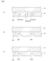
- FIG. 8A is a view showing a state in which a plurality of air bubbles are formed in the mold-coating layer
- FIG. 8B is a state in which a concave hole is formed on the inner peripheral side of the mold-coating layer
- FIG. 8C is a view showing a state in which a recessed hole having a constricted shape is formed and a recessed hole having another shape is also formed.
- FIG. 16 is an example of a 200 ⁇ m contour map of an evaluation sample of Example 8. It is a schematic diagram explaining the measuring method of the necking ratio using a microscope.
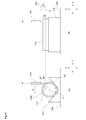
- FIG. 11 (A) is a front view of the evaluation sample observed by the microscope as viewed from the central axis side
- FIG. 11 (B) shows the evaluation sample observed by the microscope. It is the side view seen from the side.
- FIG. 16 is an example of a 150 ⁇ m contour map of an evaluation sample of Example 8. It is a schematic diagram which shows the 2 cylinder type cylinder produced for the measurement of the porosity, and the test piece obtained from this.
- FIG. 15 (A) is an external view of a two-cylinder cylinder
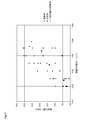
- FIG. 15 (B) is a bottom view of a test piece. It is the graph which plotted joint strength F (joint strength F (Al)) (vertical axis) to H 2 ⁇ N (horizontal axis).
- FIG. 16 is a graph in which the bonding strength F is plotted against the bonding strength index S (horizontal axis) for the experimental results of Examples 16 to 21 and Comparative Examples 7 to 9.
- FIG. 16 is a graph in which the porosity G is plotted against the bonding strength index S (horizontal axis) for the experimental results of Examples 16 to 21 and Comparative Examples 7 to 9.
- FIG. 16 is an example of a 150 ⁇ m contour map of an evaluation sample of Comparative Example 6;
- the cast iron cylindrical member according to the first embodiment is a cast iron cylindrical member, and the outer peripheral surface of the cylindrical member is formed of a cast surface and a plurality of projections P integrally formed with the cast surface. And have the following characteristics (A) to (F1).
- A) The height of the protrusion P is 0.20 mm or more and less than 0.50 mm.
- B) The total number of projections P per 1 cm 2 of the outer peripheral surface is 61 or more and 180 or less.
- the protrusion P includes a protrusion Pn having a narrowed shape.
- D The ratio of the number of protrusions Pn having a narrowed shape to the number of protrusions P present on the outer peripheral surface is 50% or more.
- E) The value S shown in the following equation (1) is 310 or more.
- the cast iron cylindrical member of the second present embodiment has the characteristics shown in the following condition (F2) instead of the condition (F1) in the cast iron cylindrical member of the first present embodiment. Except for this, the cast iron cylindrical member of the second present embodiment is the same as the cast iron cylindrical member of the first present embodiment.
- (F2) A necked shape in which the ratio of the height of the necked position to the height of the bump Pn having a necked shape is 0.65 or less with respect to the number of the bumps Pn having a necked shape existing on the outer peripheral surface The ratio of the number of protrusions Pn is 40% or more.
- the cast iron cylindrical member of the present embodiment satisfies all the conditions shown in (A) to (E), (F1) and (F2).
- the height of the projections P provided on the outer peripheral surface of the cast iron cylindrical member of the present embodiment is lower than the height of the projections provided on the outer peripheral surface of the cast iron cylindrical member exemplified in Patent Documents 1 and 2.
- the cast iron cylindrical member of the present embodiment has a total thickness T of the cast iron cylindrical member without reducing the thickness Tb of the cylindrical member main body as compared with the cast iron cylindrical members of Patent Documents 1 and 2. It is easy to make thinner.
- the projection is the outer peripheral surface of the cast iron cylindrical member so as to satisfy the conditions shown in the above (A) to (E) and (F1) or the conditions shown in the above (A) to (E) and (F2). As a result, the joint strength and adhesion between the cast iron cylindrical member and the outer peripheral side member can be sufficiently secured.
- the height H of the projection is 0.20 mm or more and less than 0.50 mm.
- the height H of the projection P is extremely easy to reduce the total thickness T of the cast iron cylindrical member.
- it is not necessary to reduce the thickness Tb of the cast iron cylindrical member main body in order to reduce the total thickness T it is possible to reduce the thickness Tb of the cast iron cylindrical member main body A reduction in strength can also be avoided.
- the height H of the projection P by setting the height H of the projection P to 0.20 mm or more, it becomes easy to form the projection Pn having a constricted shape that is effective for improving the bonding strength with the outer peripheral side member. For this reason, it becomes easy to secure sufficient joint strength.
- the height H of the projection P can be appropriately selected in the range of 0.20 mm or more and less than 0.50 mm according to the application and purpose of use of the cast iron cylindrical member of the present embodiment.
- the height H of the protrusion P is preferably 0.25 mm or more and less than 0.50 mm, and 0.30 mm or more 0
- the height H of the projection P should be 0.20 mm or more and 0.35 mm or less Is preferable and it is more preferable to set it as 0.20 mm or more and 0.30 mm or less.
- the height H of the projection P is from the outer peripheral base surface to the highest portion of the top surface of the projection P with reference to the base surface (peripheral base surface) of the projection P provided on the outer peripheral surface of the cast iron cylindrical member. Means distance.
- the outer peripheral base surface is at the same height as the area where the protrusion P is not provided in the outer peripheral surface, and the height of the protrusion P is determined based on the height of this surface (0 mm).
- the specific measuring method of the height H of the protrusion P is mentioned later.
- the total number N (density N) of projections P per 1 cm 2 of the outer peripheral surface (hereinafter, may be abbreviated as “the number of projections N”) is 61 or more and 180 or less.
- the number of projections N is 61 or more and 180 or less.
- the outer peripheral member is formed through a process of applying the liquid or powder outer peripheral member forming raw material used when forming the outer peripheral member to the outer peripheral surface (casting surface) of a cast iron cylindrical member.
- the raw material for forming the outer peripheral side member can be smoothly filled also between the adjacent protrusions P. For this reason, it can suppress that a space
- the number N of projections is more preferably in the range of 70 to 160, still more preferably in the range of 75 to 145, and particularly preferably in the range of 80 to 140.
- a material for forming the outer peripheral side member used for forming the outer peripheral side member a material which is solidified by cooling from a high temperature state, a liquid material which is hardened by a polymerization reaction, or a powder which is fused or sintered by heating Raw materials are available.
- the liquid material also includes a paste-like material.
- Specific examples of the liquid material include (i) molten metal in the case of casting, and (ii) resin material in the molten state used in injection molding or the like, or molding, coating, in the case of molding using a resin.
- the paste-like or liquid curable composition which contains as a main component the polymerizable monomer used for shaping
- Specific examples of the powdered raw materials include powders made of metals, inorganic oxides or resins, or composite materials of these.
- the protrusions P provided on the outer peripheral surface include protrusions Pn having a narrowed shape.
- the protrusion P and the protrusion Pn having a narrowed shape will be described below with reference to the drawings.
- FIG. 1 is an external perspective view showing an example of a cast iron cylindrical member according to the present embodiment
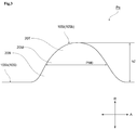
- FIG. 2 is an example of a protrusion having a constricted shape provided on the outer peripheral surface of the cast iron cylindrical member according to the present embodiment.
- FIG. 3 is an enlarged side view which shows an example of the protrusion which has the other shape provided in the outer peripheral surface of the cast iron cylindrical member of this embodiment.
- symbol A represents the central axis (or axial direction) of the cast iron cylindrical member 10
- symbol R represents the radial direction of the cast iron cylindrical member 10 orthogonal to the axial direction A.
- the radial direction R is also a direction parallel to the height direction of the protrusion P.
- the cast iron cylindrical member 10 of the present embodiment shown in FIG. 1 is provided with a plurality of projections P (not shown in FIG. 1) integrally formed with the casting surface on the outer peripheral surface 10S of the casting surface. It is done.
- FIG. 2 shows an example of the side surface shape of the protrusion P when the outer peripheral surface 10S of FIG. 1 is observed from the tangential direction TN of the outer peripheral surface 10S.
- the protrusion Pn having a narrowed shape shown in FIG. 2 is on the outer peripheral side in the radial direction R with the region (peripheral base surface 10Sb) of the outer peripheral surface 10S not provided with the protrusion Pn as a reference surface (ie height 0 mm) Protrudes by height h1 towards.
- the protrusion Pn having a narrowed shape is (i) a base portion 20B continuous from the outer peripheral base surface 10Sb side, and (ii) a portion continuous with the base portion 20B, and the radial direction R of the base portion 20B.
- the middle portion 20M provided on the outer peripheral side of (c) is a portion continuous with the middle portion 20M, and is provided on the outer peripheral side in the radial direction R of the middle portion 20M, and the top of the protrusion Pn having a narrowed shape.
- the width (the length in the direction parallel to the axial direction A) of the protrusion Pn having a narrowed shape shows a local minimum value at the intermediate portion 20M as it goes from the inner peripheral side to the outer peripheral side in the radial direction R, The maximum value is shown at 20T.
- the protrusion Pn having a narrowed shape more specifically means a protrusion satisfying the following formulas (3) to (5). -Formula (3) PT0-PM0> 0 ⁇ Equation (4) PT1 PM PM1 ⁇ Equation (5) PT2 PM PM2
- PT0 represents the width (extremely large) at the top 20T of the protrusion Pn having a narrowed shape
- PM0 represents the width at the middle portion 20M of the protrusion Pn having a narrowed shape Represents the minimum width).
- the distance from the outer peripheral base surface 10Sb (reference surface, height 0 mm) to the outer peripheral side in the radial direction R to the position showing the minimal width PM0 is referred to as the height h w of the most narrow position.
- the minimum width PM0 is equally divided into two and a line parallel to the radial direction R is defined as the center line Cp of the protrusion Pn having a narrowed shape
- PT1 represents the width of one side in the width direction
- PT2 represents the width of the other side in the width direction
- the minimum width PM0 When the line Cp is divided into two, PM1 represents the width of one side in the width direction, and PM2 represents the width of the other side in the width direction.
- the constriction amount (PT0-PM0) may be more than 0 mm, but the range is usually 0.02 mm to 0.24 mm. It is an extent.
- the actual judgment as to whether or not the projection P corresponds to the projection Pn having a narrowed shape satisfying the expressions (3) to (5) can be made on a plane orthogonal to the central axis A of the cast iron cylindrical member 10
- the side surface of the projection P is observed with a microscope from a direction forming an angle of about 30 ° away from the outer peripheral surface 10S with respect to the tangent TN on the outer peripheral surface of the cast iron cylindrical member 10. Details of the observation procedure by the microscope will be described later.
- the protrusion P which does not satisfy at least one of the expressions (3) to (5) is classified into a protrusion Pa having another shape.
- a protrusion Pa having another shape typically, the protrusion illustrated in FIG. 3 can be mentioned.
- the protrusion Pa having the other shape illustrated in FIG. 3 is the outer periphery in the radial direction R with the region (peripheral base surface 10Sb) of the outer peripheral surface 10S where the protrusion Pa is not provided as the reference surface (ie height 0 mm). It protrudes by height h2 toward the side.
- the protrusion Pa having another shape is composed of three parts of a base portion 20B, an intermediate portion 20M and a top portion 20T, similarly to the protrusion Pn having a narrowed shape shown in FIG.
- the width of the protrusion Pa having another shape is only gradually decreased from the inner peripheral side to the outer peripheral side in the radial direction R, in that the width PM0 in the middle portion 20M does not become a minimum width.
- the protrusion Pn is different from the protrusion Pn having a constricted shape.
- FIG. 4A is an example of a cross-sectional photograph (a metallurgical micrograph) of the protrusion Pn having a narrowed shape
- FIG. 4B is a side view of the protrusion Pn having a narrowed shape to a tangent line TN. It is an example of the side photograph at the time of observing with a microscope from about 30 degrees diagonally upward direction with respect to it.
- the ratio NP of the number of protrusions Pn having a narrowed shape to the number of protrusions P present on the outer peripheral surface (hereinafter sometimes abbreviated as “blink ratio NP”) is 50% or more, preferably 60% or more, 70% or more is more preferable, 80% or more is further preferable, and 90% or more is particularly preferable. Since the middle portion 20M is narrowed, the projection Pn having a narrowed shape can firmly engage the cast iron cylindrical member 10 of the present embodiment with the outer peripheral side member. Therefore, by setting the necking ratio NP to 50% or more, it becomes easy to secure sufficient bonding strength.
- the average value NP of the ratio of projections Pn having a constricted shape is the average value of the ratio of projections Pn having an individual constricted shape. A specific method of measuring the average value NP of the ratio of the protrusions Pn having a narrowed shape will be described later.
- (E) Bonding strength index S The bonding strength index S shown in Formula (1) is 310 or more, preferably 350 or more, and more preferably 500 or more. By setting the bonding strength index S to 310 or more, sufficient bonding strength can be secured.
- Patent Documents 1 and 2 it is known that the joint strength between the cast iron cylindrical member and the outer peripheral side member can be improved by providing a projection having a shape which is narrowed on the outer peripheral surface of the cast iron cylindrical member. It is done. And in patent document 1, controlling the height of the protrusion which has a narrow shape, the number of the protrusions which have a narrow shape, and the area ratio at the time of slicing the protrusion which has a narrow shape by predetermined height High bond strength. Therefore, the present inventors also attempted to improve the bonding strength by controlling individual factors considered to affect the bonding strength, such as the height H of the protrusions P, the total number N of the protrusions P, and the area ratio. . However, if the height H of the protrusion P is less than 0.5 mm, it has often been found that the joint strength can not be sufficiently secured only by controlling these factors.
- the present inventors observe a large number of projections P from the tangential direction TN and the radial direction R side, and the height H of the projections P is less than 0.5 mm and 0.5 mm or more. It was found that the contour shape of the protrusion P was largely different, and the similarity was low. From these things, when height H of projection P becomes lower compared with the past, the kind of the factor which greatly depends on joint strength and the contribution ratio of each factor to joint strength largely differ It is guessed. Therefore, as a result of trial and error, the inventors of the present invention have obtained the joint strength index S shown in the equation (1) as an extremely high index of the correlation with the joint strength in the region where the height H of the projection P is less than 0.5 mm. I found it.
- Boundary bonding strength F Bonding strength F (Al) when the outer peripheral surface of the cast iron cylindrical member of the first present embodiment is cast in aluminum alloy is equal to or higher than boundary bonding strength Fb shown in the following formula (2).
- Fb 1.325 ⁇ H 2 ⁇ N-0.75
- the cast iron cylindrical member of the first embodiment has a height H of the protrusion P of 0.2 mm or more and less than 0.5 mm. Even in the region of (1), the cast iron cylindrical member and the outer peripheral side member (other member) which casts the outer peripheral surface of the cast iron cylindrical member can be joined more firmly.
- junction strength index S having a correlation with the junction strength is, as is apparent from the equation (1), three variables (height H of protrusions P, total number N of protrusions P and ratio NP of protrusions Pn having a necked shape) It is a parameter specified by).
- the actual bonding strength is determined by the shape elements of the protrusion P, in particular, various shape elements of the protrusion Pn having a narrowed shape having a high effect of improving the bonding strength, for example, the degree of narrowing (minimum width PM0 and extremely large PT0 And the height h1 to the height h1 of the narrowest position indicating the minimum width PM0 etc.) plane shape, presence / absence of surface unevenness, degree of shape regularity / symmetry etc.
- the bonding strength index S has high correlation with bonding strength, it is not a parameter corresponding to 100% with bonding strength.
- the height H of the protrusion P is less than 0.5 mm, it is considered that the geometrical element of the protrusion P having a relatively narrowed shape compared to the height H of the protrusion P more affects the bonding strength.
- Equation (2) a parameter that also takes into account the shape of the protrusion P in a region where the height H of the protrusion P is 0.2 mm or more and less than 0.5 mm.
- the boundary bond strength Fb is defined as a function of H 2 ⁇ N.
- the geometrical elements of the protrusion P are generally bonding strength If the bonding strength F (Al) is equal to or less than Fb, the shape element of the protrusion P is generally unsuitable for improving the bonding strength. It means that it has become.
- the bonding strength F (Al) when the outer peripheral surface of the cast iron cylindrical member of the first present embodiment is cast in an aluminum alloy and the boundary shown in equation (2)
- the cast iron cylindrical member according to the first embodiment may not only form the aluminum alloy member and the composite structure, but of course, the member and the composite structure may be made of materials other than the aluminum alloy. Can also be configured.
- the ratio (hw / h1) is a ratio of the height h1 of the protrusion Pn to the height hw of the narrowest position indicating the minimum width PM0 of the protrusion Pn, as shown in FIG. It means that the narrowest position exists at a higher position in the height direction of the protrusion Pn.
- the present inventors made projections Pn having various constricted shapes having different ratios (hw / h1) with respect to projections P whose height H of projections P is 0.2 mm or more and less than 0.5 mm which is lower than the conventional one. It was observed that the smaller the ratio (hw / h1), the larger the amount of necking (PT0-PM0), and the larger the size of the top 20T.
- the top portion 20T when the size of the top portion 20T becomes larger, the top portion 20T is present in a deep biting manner on the side of the mating material (the outer peripheral side member) joined to the cast iron cylindrical member. Therefore, as the ratio NP2 is larger, the bonding strength between the cast iron cylindrical member and the outer peripheral member can be increased, and in particular, by setting the ratio NP2 to 40% or more, as compared with the prior art such as Patent Document 3 and the like. Even in the region where the height H of the protrusion P is 0.2 mm or more and less than 0.5 mm, the bonding strength can be significantly improved.
- the cast iron cylindrical member 10 of the present embodiment at least satisfies the conditions shown in (A) to (E) and (F1) described above or the conditions shown in (A) to (E) and (F2).
- the area ratio S1 is preferably 15% to 50%, more preferably 20% to 50%.
- the base portion 20B of the protrusion P is thick and the protrusion P is less likely to be broken, so it is easier to secure sufficient bonding strength.
- the area ratio S1 to 50% or less it is possible to suppress that the base portion 20B of the protrusion P and the casting surface around it become rough.
- the area ratio S1 is measured by irradiating the outer peripheral surface 10S of the cast iron cylindrical member 10 with laser light using a non-contact three-dimensional laser measurement device to measure 1 cm 2 of the outer peripheral surface 10S.
- the area of the area including the area surrounded by the contour lines and the borderline that forms the periphery of the measurement area
- surrounded by the contours of the measurement height 0.15 mm Means a ratio.
- the use of the cast iron cylindrical member 10 of the present embodiment is not particularly limited, generally, at least a part of the outer peripheral surface 10S is covered with the outer peripheral side member (another member), thereby making the cast iron cylindrical member It is particularly preferable to be used in the state where 10 and the outer peripheral side member are integrated. In this case, it has the cast iron cylindrical member 10 of the present embodiment and an outer peripheral side member covering at least a part of the outer peripheral surface 10S of the cast iron cylindrical member 10 of the present embodiment.
- the outer peripheral side member is a metal outer peripheral side member such as aluminum alloy, magnesium alloy or iron alloy, and at least a part of the outer peripheral surface of the cast iron cylindrical member is casted by the metal outer peripheral side member It is preferable that it is a cast-in-cast structure. Before and after the cast iron cylindrical member 10 and the outer peripheral side member are integrated, the inner peripheral surface of the cast iron cylindrical member 10 may be subjected to processing such as cutting.
- a state in which the cast iron cylindrical member 10 and the outer peripheral side member are integrated means that the outer peripheral surface 10S is covered with the liquid or powder outer peripheral side member forming raw material, For example, if it is a powdery raw material, it is fused, sintered or the like by heating to form an outer peripheral side member, whereby the cast iron cylindrical member 10 and the outer peripheral side member are joined.
- the liquid raw material or the powdery raw material is filled between the plurality of projections P located adjacent to each other on the outer circumferential surface 10S, and is also filled in the constricted portion of the constricted projection Pn. .
- the projections P in particular, the projections Pn having a narrowed shape can be firmly engaged with the outer peripheral side member, and high bonding strength can be obtained.
- the material which comprises an outer peripheral side member is suitably selected according to the use of cast iron cylindrical member 10, it is normal that the material of the kind different from the material which comprises cast iron cylindrical member 10 is used preferable. However, if necessary, it is also possible to use the same kind of material as that of the cast iron cylindrical member 10 as the material of the outer peripheral side member.
- the use of the cast iron cylindrical member 10 of the present embodiment is not particularly limited, for example, it is particularly preferable to use it as a cylinder liner or a brake drum.
- FIG. 5 is a schematic view showing an example of an internal combustion engine provided with the cast iron cylindrical member (cylinder liner) of the present embodiment.
- the internal combustion engine 20 shown in FIG. 5 has a structure in which a plurality of cylinder liners 30 and a cylinder block 32 (outer side member) into which the plurality of cylinder liners 30 are cast are integrated.
- the coolant flow passage 36 is provided between two adjacent cylinder bores 34.
- the coolant flow channel 36 is exactly provided between the outer circumferential surfaces 10S of two adjacent cylinder liners 30.
- the other members other than the cylinder liner 30 and the cylinder block 32, and the projections P provided on the outer circumferential surface 10S are not shown.
- the thickness T of the cylinder liner 30 shown in FIG. 5 means the total thickness including the height of the projections P.
- a member in which the inner peripheral surface (casting surface) of the cast iron cylindrical member 10 of the present embodiment immediately after casting is processed is used.
- an aluminum alloy material can be used, for example in consideration of weight reduction and cost.
- the aluminum alloy for example, “JIS ADC10 (related standard US ASTM A380.0)” or “JIS ADC12 (related standard US ASTM A383.0)” can be used.
- the cooling efficiency of the cylinder bores 34 can be enhanced by enlarging the flow passage diameter (outer diameter D) of the cooling fluid flow passage 36 provided between two adjacent cylinder bores 34.
- the thickness B between the cylinder bores 34 is 8 mm
- the outer diameter D of the coolant flow channel 36 is 3 mm
- the thickness T of the cylinder liner 30 is 2.5 mm
- the space between the cylinder liner 30 and the coolant flow channel 36 The wall thickness is 0 mm.
- the coolant such as water flowing in the coolant flow path 36 leaks into the combustion chamber and the crankcase through the outer peripheral surface of the cylinder liner 30, and this leak causes engine malfunction. It may also occur.
- the thickness of the cylinder liner 30 main body excluding the protrusion P is made thinner than the thickness T of the cylinder liner 30.
- the wall thickness B between the cylinder bores 34 needs to be thicker.
- the thickness of the cylinder liner 30 main body excluding the projection P is further reduced, the strength of the cylinder liner 30 is reduced, and the cylinder bore 34 is easily deformed. Further, if the thickness B between the cylinder bores 34 is increased, the cooling performance of the internal combustion engine 20 is reduced.
- the thickness between the cylinder bores 34 is The thickness between the cylinder liner 30 and the coolant flow passage 36 can be set to a value exceeding 0 mm without making the thickness B thicker or making the thickness of the main body of the cylinder liner 30 thinner.
- the outer diameter D of the coolant flow channel 36 can also be increased.
- the thickness of the cylinder liner 30 can be reduced by 0.40 mm. Therefore, when designing the cross-sectional structure between the cylinder bores 34, a margin of 0.80 mm can be obtained. Therefore, utilizing this margin, the wall thickness of the portion (cylinder block 32) between the cylinder bores 34 excluding the cylinder liner 30 can be thinned while maintaining the strength of the cylinder liner 30, or the coolant flow path By enlarging the outer diameter D of 36, the cooling performance of the internal combustion engine 20 can be improved.
- the bonding strength between the cylinder liner 30 and the cylinder block 32 is insufficient, deformation of the cylinder bore 34 is likely to occur, resulting in an increase in friction between the piston or piston ring and the cylinder liner 30.
- the adhesion at the joint interface between the cylinder liner 30 and the cylinder block 32 is insufficient, high heat generated by engine combustion is less likely to be transferred from the cylinder liner 30 side to the cylinder block 32 side. It tends to cause deterioration of the cooling performance.
- the cast iron cylindrical member 10 of the present embodiment is used as the cylinder liner 30, the above-described problems are largely suppressed because the joint strength and adhesion between the cylinder liner 30 and the cylinder block 32 are excellent. It is easy to do.
- the height H of the projections P is low and the number N of projections is large, which is advantageous for the uniformity of heat radiation from the outer peripheral surface 10S.
- FIG. 6 is a schematic cross-sectional view showing an example of the inscribed drum brake provided with the cast iron cylindrical member (brake drum) of the present embodiment, in which the wheel is cut along a plane including the rotation axis of the wheel. Is shown. In FIG. 6, the projection P is not shown.
- the brake drum 44 (this embodiment) is formed on the inner circumferential surface 42S of the substantially cylindrical drum portion 42 (outer side member) that forms a part of the wheel 40 whose center of rotation is the center line L. Cast iron cylindrical member 10) is mounted by casting.
- a brake shoe 46 is disposed on the inner circumferential surface 44S side of the brake drum 44. At the time of braking, the brake shoe 46 contacts and slides on the inner circumferential surface 44S of the brake drum 44.
- an aluminum alloy, a magnesium alloy or the like can be used in consideration of weight reduction and strength.
- the manufacturing method of the cast iron cylindrical member of this embodiment is demonstrated.
- the composition of the cast iron used as the raw material of the cast iron cylindrical member of this embodiment is not specifically limited, It can select suitably according to the use application of the cast iron cylindrical member of this embodiment.
- the composition shown below can be illustrated as a composition of flake graphite cast iron equivalent to JIS FC 250 in consideration of wear resistance, seizure resistance and processability.
- Mn 0.5 to 1.0 mass%
- P 0.25% by mass or less
- S 0.15% by mass or less
- Cr 0.5% by mass or less
- the base structure is pearlite
- the graphite area ratio is 10% or more
- the steatite as eutectic hardened material phase is 2% or less
- the free ferrite is 5% or less
- mechanical strength is
- the hardness can be 94 to 104 HRB
- the tensile strength can be 250 MPa or more.
- the cast iron cylindrical member 10 of the present embodiment is manufactured by a centrifugal casting method including [Step A] to [Step F] shown in FIG.
- the height H of the protrusion P is less than 0.5 mm.
- the present inventors have reviewed the entire process of centrifugal casting, and even if the height H of the projection P is set to less than 0.5 mm, according to [Step A] to [Step F] described in detail below. It has been found that if the height of P is 0.20 mm or more, a protrusion Pn having a sufficient number of narrowed shapes can be formed.
- the present inventors when combining the mold wash having a predetermined composition used in [Step C] with the temperature of the cylindrical mold within the predetermined range in [Step C], the prior art, particularly, It has been found that as compared with the technique described in Patent Document 3, it is possible to form a protrusion P having an advantageous shape factor by the improvement of the bonding strength.
- step A a refractory base, a binder and water are mixed in a predetermined ratio to prepare a suspension.
- a range selectable as the compounding amount of the fireproof substrate, the caking agent, and water, and a range selectable as the average particle diameter of the fireproof substrate are preferably set as follows.
- Blending amount of refractory base material 25% by mass to 35% by mass
- Blending amount of caking agent 3% by mass to 9% by mass
- Water content 62% by mass to 66% by mass
- Average particle size of refractory base material 0.002 mm or more and 0.010 mm or less
- [Fireproof substrate] By setting the compounding amount of the refractory base material to 25% by mass or more, the heat insulating effect of the mold-forming agent can be sufficiently ensured, and it becomes easy to obtain the cast iron cylindrical member 10 having a desired cast iron base structure. Further, by setting the compounding amount to 35% by mass or less, it becomes easy to uniformly apply the coating agent to the inner peripheral surface of the mold without reducing the flowability of the coating agent, so the cast iron cylinder It becomes easy to ensure the outer diameter accuracy of the member 10.
- diatomaceous earth can be used as a fireproof base material.
- Average particle size of refractory base material By setting the average particle diameter of the refractory base material to 0.002 mm or more, it becomes easy to form the projections Pn having a sufficient number of constricted shapes. As a result, securing of joint strength is also facilitated. Further, by setting the average particle diameter to 0.010 mm or less, it is possible to prevent the inner circumferential surface of the moldable layer formed of the mold wash from being roughened more than necessary. As a result, it becomes easy to smooth the outer peripheral base surface 10Sb that spreads around the protrusion P, and the adhesion between the outer peripheral base surface 10Sb and the outer peripheral member is improved, and generation of voids at the interface between both is suppressed. It becomes easy to do.
- the blending amount of water is 62% by mass or more, the flowability of the coating agent is not reduced, and the coating agent is uniformly applied to the inner peripheral surface of the mold, so that the outer diameter accuracy of the cast iron cylindrical member 10 is improved. Secure. Further, when the blending amount of water is 66% by mass or less, the necessary bonding strength of the mold wash is secured, and the formation of the projections P becomes easy.
- step B a predetermined amount of surfactant is added to the suspension prepared in step A to prepare a mold wash.
- the surfactant is preferably added in the range of 0.005 parts by mass to 0.04 parts by mass with respect to 100 parts by mass of the suspension mass.
- the addition amount of the surfactant is 0.005 parts by mass or more, so that the foaming action of the surfactant in the mold-forming layer is sufficiently exhibited, so that the formation of the projections P becomes easy. As a result, it also becomes easy to ensure sufficient bonding strength.
- the addition amount of the surfactant to 0.04 parts by mass or less, the foaming action of the surfactant is prevented from being excessive, and it becomes easy to form the protrusion Pn having a constricted shape. As a result, it also becomes easy to ensure sufficient bonding strength.
- the total number of the projections P to be formed does not increase more than necessary, it is also possible to fill the outer peripheral side member forming raw material without gaps between the plurality of projections P adjacent on the outer peripheral surface 10S when forming the outer peripheral side member. It will be easier. For this reason, it becomes easy to ensure adhesion by preventing the generation of a void at the bonding interface.
- step C in step C, as shown in FIG. 8A, a coating agent is spray applied to the inner circumferential surface 50S of the cylindrical mold 50 (mold) in a rotating state heated to a temperature of 180 ° C. to 240 ° C. . At this time, the coating agent is applied so that the layer (coating layer 52) of the coating agent is formed to have a substantially uniform thickness over the entire circumference of the inner circumferential surface 50S.
- the projection P is presumed to be formed through the process described below.
- the water in the mold-coating agent evaporates rapidly to form a plurality of air bubbles 54A (FIG. 8A).
- the surfactant acts on the relatively large sized bubbles 54A1 (54A), or the relatively small sized bubbles 54A2 (54A) combine with each other to form the inside of the mold-forming layer 52.
- a recessed hole 54B is formed on the circumferential side (FIG. 8 (B)).
- the moldable layer 52 is gradually dried from the inner circumferential surface 50S of the cylindrical mold 50, and the mold is formed in the process of gradually solidifying the moldable layer 52 forming the recessed hole 54B from the cylindrical mold 50 side.
- a recessed hole 54C1 having a constricted shape is formed in the layer 52.
- a concave hole 54C2 having another shape different from the concave hole 54C1 may be formed in the mold coating layer 52 from part of the concave hole 54B (FIG. 8 (C)).
- the thickness of the moldable layer 52 is preferably selected in the range of 1.4 times to 2.0 times the height H of the protrusions P. It is particularly preferable to set the temperature of the cylindrical mold 50 to 240 ° C. or less as described above when the thickness of the moldable layer 52 is in this range. When the temperature of the cylindrical mold 50 exceeds 240 ° C., the cylindrical mold 50 side of the moldable layer 52 is solidified in a short time because the drying speed of the moldable layer 52 is fast. At this time, when the recessed holes 54B are formed in the moldable layer 52 by the action of the surfactant also on the small air bubbles 54A2 present in the moldable layer 52, the small bubbles 54A2 are gathered, and the protrusion P is formed.
- the thin flat-shaped projection P appears in the top 20T of the The outer peripheral surface 10S of the cast iron cylindrical member 10 is covered with the projection P having the flat top 20T, and the area of the outer peripheral base surface 10Sb seen from the outer peripheral surface 10S side is reduced. Therefore, when forming the outer peripheral side member, it becomes difficult to fill the outer peripheral side member forming raw material on the outer peripheral surface 10S of the cast iron cylindrical member 10 without a gap, and sufficient bonding strength and adhesion (small porosity) are secured. become unable.
- the temperature difference between the cylindrical mold 50 in step C and the cylindrical mold 50 in step E be small, specifically 180 ° C. or higher. preferable.
- the time when the temperature of the cylindrical mold 50 becomes highest between the process D and the process E is the time when the cast iron cylindrical member is taken out from the cylindrical mold 50 in the process E.
- step D after the mold layer 52 is dried, cast iron is cast into the cylindrical mold 50 in a rotating state. At this time, the molten metal is also filled in the concave holes 54C1 and 54C2 of the moldable layer 52, whereby the projection P of the cast iron cylindrical member 10 is formed.
- the concave hole 54C1 corresponds to the protrusion Pn having the narrowed shape shown in FIG. 2
- the concave hole 54C2 corresponds to the protrusion Pa having another shape shown in FIG. 3.
- the projections Pn and the projections Pa formed on the outer peripheral surface 10S are viewed from the top surface 10St side under the casting conditions described above, the projections Pn and the top surface 10St of the projections Pa are substantially flat and dented in the center It has a tendency to have a substantially flat shape, an open-leafed crown, or an open-leafed crown with a central depression.
- step E after the molten metal solidifies and the cast iron cylindrical member 10 is formed, the cast iron cylindrical member 10 is taken out from the cylindrical mold 50 together with the mold-forming layer 52. The temperature of the cylindrical mold 50 is the highest at this point.
- step F the moldable layer 52 is removed from the outer peripheral surface 10S of the cast iron cylindrical member 10 by a blasting apparatus.
- the present invention will be described by way of examples, but the present invention is not limited to the following examples.
- the first experiment shown below is an experiment mainly for evaluating the influence of the mold wash, and the second experiment is an experiment mainly for evaluating the influence of the mold temperature.
- the coating agents A1 to A5 used in the preparation of the cast iron cylindrical members of the respective examples were selected from the composition of the suitable coating agent prepared in step A and step B described above and the average particle diameter of the refractory substrate. It is something to meet.
- the coating agents B1 to B5 used for producing the cast iron cylindrical members of the respective comparative examples to be described later have the composition of the suitable coating agent produced in the steps A and B described above and the average particle diameter of the fireproof substrate It does not satisfy either.
- the composition of the mold wash used in Example 1 of Patent Document 1 is the same as that of Example 1 except that the amount of surfactant B1 is changed so that the amount of surfactant added is the same as that of the paint A1 to A5. It was imitated and prepared.
- the temperature of the cylindrical mold 50 in step C is set within the range of 180 ° C. to 240 ° C., and the mold layer 52 is formed. It formed.
- the thickness of the moldable layer 52 was appropriately changed in each of the examples and the comparative examples.
- the cast iron cylindrical member having different heights H of the projections P by providing three levels of thickness of the mold forming layer 52 formed using the same type of mold wash was produced.
- the process D or subsequent one when producing the cast iron cylindrical member of any Example and a comparative example, it implemented on the same conditions. Thereafter, the inner peripheral surface of the obtained cast iron cylindrical member was cut to adjust the thickness to 5.5 mm.
- the dimensions of the iron cylindrical members of each of the Examples and Comparative Examples obtained through the process described above are 85 mm in outer diameter (outer diameter including height H of protrusion P) and 74 mm in inner diameter (thickness 5. 5 mm) and the axial length is 130 mm.
- the composition and dimensions of the cast iron cylindrical members of each of the Examples and Comparative Examples prepared as evaluation samples can be used as a cylinder liner.
- the projection number N is obtained by measuring the outer peripheral surface of the cast iron cylindrical member of each example and comparative example using a non-contact three-dimensional laser measurement device to obtain a contour map of 1 cm long ⁇ 1 cm wide, and then this contour line The number of regions surrounded by contour lines with a height of 200 ⁇ m in the figure was calculated by counting. The specific measurement method is described below.
- the evaluation sample 110 (cast iron cylindrical member) was placed on the measurement table 102 (V block) installed on the XY table 100.
- the evaluation sample 110 was obtained from the laser irradiation unit 122 provided below the non-contact three-dimensional laser measurement instrument 120 (laser focus displacement meter: LT series manufactured by Keyence) disposed above the evaluation sample 110.
- the inside of a predetermined area of the outer peripheral surface 110S of the sample for evaluation 110 was scanned with the laser L by moving the XY table 100 in the horizontal direction while irradiating the laser L toward the outer peripheral surface 110S.
- the X-axis direction is a direction parallel to the central axis A of the evaluation sample 110.
- a direction (direction perpendicular to the sheet of the drawing) perpendicular to both the X-axis direction and the Z-axis direction (vertical direction) is the Y-axis direction
- the horizontal direction means a direction parallel to the XY plane.
- the Y axis ranges from -5.0 mm to +5 for the range from -5.0 mm to +5.0 mm.
- the XY table 100 was moved at intervals of 0.1 mm for the range up to .0 mm.
- the inside of the measurement area of the outer peripheral surface 110S was scanned by the laser L.
- the scanning speed of the laser L at this time is 5500 ⁇ m / sec.
- the position in the measurement area in the Z-axis direction is measured as coordinate Z at each coordinate (X, Y).
- the measurement resolution in the Z-axis direction at this time is 0.1 ⁇ m.
- the irradiation conditions of the laser L are a spot diameter of 0.007 mm and a focal depth of 2 mm.
- correction processing for planarizing the XY plane formed of the curved surface is performed for coordinate data (X, Y, Z) obtained by scanning the laser L in the measurement area.
- coordinate data (X, Y, Z) after correction is subjected to arithmetic processing by spreadsheet software to be imaged to obtain a contour image of the measurement area.
- FIG. 10 shows an example of a 200 ⁇ m contour map of the evaluation sample of the eighth embodiment.
- the black area in FIG. 10 is an area with a Z-axis height of 0.20 mm or more.
- the ratio (major axis / minor axis) of the major axis to the minor axis of the contour shape of this one closed region is 2 or more with one closed region of “flat shape or wedge shape” which is not to be counted.
- (3) The total number n (pieces / cm 2 ) of the protrusions P in the measurement area is obtained based on the following equation (6).
- n n20 + nb20 / 2
- n20 represents the total number (number / cm 2 ) of the area surrounded by only the 0.20 mm height Z-axis height to be counted in the 200 ⁇ m contour map
- nb20 Represents the total number (number / cm 2 ) of the region surrounded by the Z-axis height of 0.20 mm and the boundary of the 200 ⁇ m contour map within the 200 ⁇ m contour map.
- the total number n of projections P is calculated after rounding off to an integer value.
- the measurement described above is performed at the same four measurement points as when measuring the height H of the projection P, and the average value of the total number n of the projections P at the four measurement points is the number N of projections (number of projections It calculated
- the necking ratio NP was determined by the following procedure. First, as shown in FIG. 11, the evaluation sample 110 was placed on a V block base 210 having a substantially V-shaped cross section installed on a horizontal table 200. Further, obliquely above the evaluation sample 110, a microscope 220 (digital microscope KH-1300 manufactured by Hilux Co., Ltd.) connected to a television monitor (not shown in the figure) is attached to the optical axis M of the microscope 220. Are arranged parallel to the Z-axis direction (vertical direction).
- the outer peripheral surface of the evaluation sample 110 in the circumferential direction P of the evaluation sample 110 When the upper side of the microscope 220 in the Z-axis direction orthogonal to the central axis A of the evaluation sample 110 is 0 degree, the outer peripheral surface of the evaluation sample 110 in the circumferential direction P of the evaluation sample 110. It is arranged to be able to observe the position of about 60 degrees of 110S. Thereby, the tangent TN on the outer circumferential surface 110S of the measurement area portion observed by the microscope 220 and the optical axis M of the microscope 220 are set to form an angle of about 30 degrees. In addition, the magnification of the eyepiece lens of the microscope 220 was 40 times.
- the X-axis direction is a direction parallel to the central axis A of the evaluation sample 110
- the Y-axis direction is a direction orthogonal to both the X-axis direction and the Z-axis direction.
- the auxiliary light source 230 was disposed slightly above the observation position Ob of the microscope 220 on the outer circumferential surface 110S of the evaluation sample 110 and at one end of the evaluation sample 110. Then, light was irradiated from the auxiliary light source 230 in a direction substantially parallel to the axial direction A of the evaluation sample 110. At this time, the position of the auxiliary light source 230, the irradiation direction of the light, and the like were finely adjusted so that the light strikes the side surface of the projection P reflected on the television monitor and reflects.
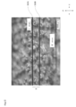
- FIG. 12 is an enlarged image showing an example of the outer peripheral surface 110S of the evaluation sample 110 displayed on the television monitor, and the vertical direction in the drawing represents the circumferential direction P of the evaluation sample 110, and the horizontal direction X in the drawing. Is a direction parallel to the central axis A of the evaluation sample 110.
- the number of the protrusions P located on the cursor lines 300A and 300B was counted as one only when half or more of the protrusions P were present in the measurement area B, and was counted as zero otherwise. Further, as the protrusions P to be counted, as illustrated in FIG. 2 and FIG. 3, the entire periphery of the protrusion P having one top portion 20T is substantially surrounded by only the outer peripheral base surface 10Sb, Only those separated from the projection P were considered. Therefore, one protrusion P1 as illustrated in FIG. 13 is not substantially separated from the other protrusion P2 by the outer peripheral base surface 10Sb, and the space between the protrusion P1 and the protrusion P2 is with respect to the outer peripheral base surface 10Sb.
- the projection group Pi in a state of being connected by the connecting portion 20C having a height smaller than the height h3 of the projection P1 and the height h4 of the projection P2 is excluded from counting.
- the measurement described above is carried out at the same four measurement points as when measuring the height H of the projection P, and has the number q0 of projections Pa and a constricted shape having other shapes at each measurement point.
- the number q1 of projections Pn was obtained.
- the necking ratio NP was calculated based on the following equation (7).
- ⁇ Formula (7) necking ratio NP (%) Total value of q1 of 100 ⁇ 4 measurement points / (total value of q 0 of 4 measurement points + total value of q 1 of 4 measurement points)
- the area ratio S1 is calculated by calculation using spreadsheet software based on corrected coordinate data (X, Y, Z) at four measurement points obtained when measuring the number of protrusions N, and four areas are calculated. It calculated
- the Z-axis height of the outer peripheral base surface 10Sb confirmed in the contour image drawn from the spreadsheet software is set to the reference value (0 mm)
- the contour line having the Z-axis height of less than 0.15 mm is not displayed By doing this, a contour map (150 ⁇ m contour map) was obtained by slicing the measurement area at a height of 0.15 mm on the Z-axis.
- FIG. 14 shows an example of a 150 ⁇ m contour map of the evaluation sample of Example 8.
- the black area in FIG. 14 is an area with a Z-axis height of 0.15 mm or more.
- the 150 ⁇ m contour map shown in FIG. 14 corresponds to the 200 ⁇ m contour map shown in FIG. 10 with the slice position lowered by 50 ⁇ m.
- the area ratio s of each measurement point is a value defined by the following equation (8).
- ⁇ Formula (8) area ratio s (%) 100 ⁇ ps / bs
- [e] porosity G In order to measure the porosity G, first, two-cylinder cylinders manufactured using the cast iron cylindrical members of the respective examples and the comparative examples were manufactured. As shown in FIG. 15A, in the two-cylinder cylinder 400, the entire outer peripheral surface of two cast iron cylindrical members 410 (cylinder liners) manufactured as a sample for evaluation is die cast using an aluminum alloy. I made it by turning around. The die casting conditions at this time are as follows.
- Bonding strength F bonding strength F (Al)) From the first test piece 402 used for evaluation of the porosity G, a portion (second test piece A) shown in the following (a) to (c) and a portion (second test piece shown in the following (d) B) cut out. (A) On both end sides of the first test piece 402 in the longitudinal direction, the first test piece 402 was cut out with a width of 20 mm along the circumferential direction centering on the portion where the first test piece 402 and the straight line M1 intersect. portion.
- the second test piece A has a two-layer structure in which a portion formed of a cast iron cylindrical member 410 having a concave surface on one side and a portion formed of a cylinder block 420 having a convex surface on the other side are integrated. It is a cutting piece.
- the second test piece B is a cut piece having a three-layer structure, and the layers on both sides are portions consisting of a cast iron cylindrical member 410 forming a concave surface, and the central portion integrated with the layers on both sides.
- the layer is the portion consisting of the cylinder block 420.
- arms for a tensile test provided with adhesive surfaces corresponding to the uneven shapes on both sides of the second test pieces A and B were adhered to both sides of the second test pieces A and B.
- a tensile tester manufactured by Shimadzu Corporation, universal tester: AG-5000E
- AG-5000E tensile tester
- the tensile load when the portion formed of the cast iron cylindrical member 410 constituting the second test pieces A and B and the portion formed of the cylinder block 420 were separated was measured as the bonding strength f. Then, the average value of the bonding strength f of the six second test pieces A and the bonding strength f of the one second test piece B was determined as the bonding strength F.
- the bonding strength F is also the bonding strength F (Al) to be compared with the boundary bonding strength Fb.
- Tables 2 and 3 show the results of measuring the cast iron cylindrical members of the respective examples and comparative examples by the respective measuring methods described above.
- evaluation criteria for thinning evaluation, porosity evaluation, and bonding strength evaluation shown in Table 3 are as follows.
- Bonding strength F is 10.0 MPa or more.
- Bonding strength F is 6.0 MPa or more and less than 10.0 MPa.
- C Bonding strength F is less than 6.0 MPa.
- Table 6 shows the ratio (hw / h1) of the height hw at the narrowest position to the height h1 of the protrusion Pn having the narrow shape, 0 ⁇ hw / h1 ⁇ 0.35, 0.35 ⁇ hw
- the ratios A, B, and C of the projections Pn in each section when divided in the range of / h1 0.6 0.65 and 0.65 ⁇ hw / h1 ⁇ 1.0 are shown.
- Table 6 also shows the ratio NP2 and the temperature of the cylindrical mold 50.
- [g] ratio A, B, C and NP2 The ratios A, B and C shown in Table 6 were determined by the following procedure. First, positions of 20 mm to 30 mm from both ends of the cast iron cylindrical members of the respective examples and comparative examples were cut so that a cross section orthogonal to the axial direction was exposed. Next, the cut surface was polished using polishing paper while changing the roughness of the polishing paper in the order of medium size, fine size, and very fine size (# 1000 or more). By carrying out this polishing process on three cast iron cylindrical members, six measurement samples having a thickness of 20 mm to 30 mm having a cut surface after polishing were produced.
- the cross-sectional shape of the protrusion Pn having a narrowed shape present on the outer peripheral end of the cut surface after polishing is connected to a microscope 220 (a digital microscope KH-1300 made by Hilux Co., Ltd.) connected to a television monitor with software for analysis , And eyepiece magnification: 100 times).
- a microscope 220 a digital microscope KH-1300 made by Hilux Co., Ltd.
- the height h1 and the height hw at the most narrowed position were measured for the cross-sectional shape of the protrusion Pn having the individual narrowed shape observed.
- 24 protrusions Pn having a narrowed shape were randomly selected for each measurement sample, and the cross-sectional shape of the protrusions Pn having a total of 144 narrowed shapes was observed.
- the division A (0 ⁇ hw / h1 ⁇ 0.35) and the division B (0.35 ⁇ hw / h1 ⁇ 0.) Regarding the ratio (hw / h1).
- 65) and C classification (0.65 ⁇ hw / h1 ⁇ 1.0), and the number of protrusions Pn having a constricted shape belonging to each classification was determined.
- the numbers A, B, and C shown in Table 6 were obtained by dividing the number of protrusions Pn having a narrowed shape belonging to each section by the total number (144) of observation targets.
- the ratio NP2 was also determined from the sum of the ratio A and the ratio B.
- FIG. 16 shows a graph in which the bonding strength F (bonding strength F (Al)) (vertical axis) is plotted against H 2 ⁇ N (horizontal axis).
- the graph shown in FIG. 16 shows the case where the height H of the projection P is 0.2 mm or more and less than 0.5 mm.
- the test examples (Examples 1, 4-6, 8-9 and Comparative Examples 1-2, 4) disclosed in Table 1 of Patent Document 3 are also plotted. .
- the bonding strength F indicates a value exceeding the boundary bonding strength Fb.
- the joint strength F joint strength F (joining) is eliminated except for the comparative example 3 in which the practical joint strength F (the joint strength F (Al)) is not obtained
- the strength F (Al)) is lower than the boundary bonding strength Fb.
- the bonding strength F (bonding strength F (Al)) is significantly lower than the boundary bonding strength Fb.
- the cast iron cylindrical member of the present embodiment has the shape element of the protrusion P in comparison with the comparative example and the test example disclosed in Table 1 of Patent Document 3 Overall, it is considered to be more suitable for improving the bonding strength.
- FIG. 17 shows a graph in which the bonding strength F (vertical axis) is plotted against the height H (horizontal axis) of the protrusion P.
- the graph shown in FIG. 17 shows the case where the height H of the protrusion P is 0.2 mm or more and less than 0.5 mm.
- the test examples (Examples 1, 4-6, 8-9 and Comparative Examples 1-2, 4) disclosed in Table 1 of Patent Document 3 are also plotted. .
- the height H of the protrusion P is lower in the example compared to the comparative example and the test example disclosed in Table 1 of Patent Document 3 I see that I can do it. Therefore, in the composite structure using the cast iron cylindrical member of the present embodiment, it is possible to further reduce the thickness in the vicinity of the joint between the cast iron cylindrical member and the outer peripheral side member while securing the same joint strength as before. It can be said that it will be easier.
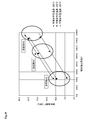
- FIG. 18 shows a graph in which the bonding strength F is plotted against the bonding strength index S (horizontal axis) for the experimental results of Examples 16 to 21 and Comparative Examples 7 to 9, and FIG. 19 shows Examples 16 to 21. And the graph which plotted the porosity G with respect to joint strength index S (horizontal axis) is shown about the experimental result of Comparative Examples 7-9. In these graphs, the production conditions (cylindrical mold temperature and type of coating agent) are also shown.
- the joint strength index S is a parameter in which only the narrowing ratio NP is reflected among the shape elements of the protrusion P, and the shape elements of the protrusion P other than the narrowing ratio NP are not reflected.
- the phenomenon shown in the above (ii) is that as the temperature of the cylindrical mold decreases from 280.degree. C. to 240.degree. C., the shape elements of the projections P other than the necking ratio NP have the bonding strength F. It is considered to suggest that it has changed to increase significantly. Further, based on the results shown in FIG. 19, it is considered that the change in the shape factor of the protrusion P other than the constriction ratio NP is also closely related to the change in the porosity G.
Landscapes
- Engineering & Computer Science (AREA)
- Mechanical Engineering (AREA)
- General Engineering & Computer Science (AREA)
- Chemical & Material Sciences (AREA)
- Combustion & Propulsion (AREA)
- Cylinder Crankcases Of Internal Combustion Engines (AREA)
- Pistons, Piston Rings, And Cylinders (AREA)
- Pressure Welding/Diffusion-Bonding (AREA)
- Braking Arrangements (AREA)
- Laminated Bodies (AREA)
Abstract
Priority Applications (7)
| Application Number | Priority Date | Filing Date | Title |
|---|---|---|---|
| JP2017560831A JP6340148B1 (ja) | 2017-11-17 | 2017-11-17 | 鋳鉄製円筒部材および複合構造体 |
| BR112018069180-1A BR112018069180B1 (pt) | 2017-11-17 | 2017-11-17 | Membro cilíndrico de ferro fundido e estrutura composta |
| EP17894667.9A EP3505271B1 (fr) | 2017-11-17 | 2017-11-17 | Élément cylindrique en fonte et structure composite |
| CN201780016982.5A CN109072809B (zh) | 2017-11-17 | 2017-11-17 | 铸铁制圆筒部件和复合结构体 |
| KR1020187028065A KR101927284B1 (ko) | 2017-11-17 | 2017-11-17 | 주철제 원통부재 및 복합 구조체 |
| US16/090,123 US10596624B2 (en) | 2017-11-17 | 2017-11-17 | Cast-iron cylindrical member and composite structure |
| PCT/JP2017/041498 WO2019097678A1 (fr) | 2017-11-17 | 2017-11-17 | Élément cylindrique en fonte et structure composite |
Applications Claiming Priority (1)
| Application Number | Priority Date | Filing Date | Title |
|---|---|---|---|
| PCT/JP2017/041498 WO2019097678A1 (fr) | 2017-11-17 | 2017-11-17 | Élément cylindrique en fonte et structure composite |
Publications (1)
| Publication Number | Publication Date |
|---|---|
| WO2019097678A1 true WO2019097678A1 (fr) | 2019-05-23 |
Family
ID=62487404
Family Applications (1)
| Application Number | Title | Priority Date | Filing Date |
|---|---|---|---|
| PCT/JP2017/041498 Ceased WO2019097678A1 (fr) | 2017-11-17 | 2017-11-17 | Élément cylindrique en fonte et structure composite |
Country Status (7)
| Country | Link |
|---|---|
| US (1) | US10596624B2 (fr) |
| EP (1) | EP3505271B1 (fr) |
| JP (1) | JP6340148B1 (fr) |
| KR (1) | KR101927284B1 (fr) |
| CN (1) | CN109072809B (fr) |
| BR (1) | BR112018069180B1 (fr) |
| WO (1) | WO2019097678A1 (fr) |
Cited By (2)
| Publication number | Priority date | Publication date | Assignee | Title |
|---|---|---|---|---|
| JP6780156B1 (ja) * | 2020-06-24 | 2020-11-04 | Tpr株式会社 | 鋳包み用シリンダライナ |
| JP6925559B1 (ja) * | 2020-06-18 | 2021-08-25 | Tpr株式会社 | スパイニライナ及びその製造方法、並びに接合強度の鑑別法 |
Families Citing this family (2)
| Publication number | Priority date | Publication date | Assignee | Title |
|---|---|---|---|---|
| CN109915273B (zh) * | 2018-05-24 | 2020-06-30 | 帝伯爱尔株式会社 | 圆筒部件 |
| CN117189405A (zh) * | 2022-06-01 | 2023-12-08 | 中原内配集团安徽有限责任公司 | 一种毛刺状铸入式气缸套 |
Citations (3)
| Publication number | Priority date | Publication date | Assignee | Title |
|---|---|---|---|---|
| JP2003326353A (ja) * | 2002-05-13 | 2003-11-18 | Honda Motor Co Ltd | 鋳鉄製鋳ぐるみ部材 |
| JP2005194983A (ja) * | 2004-01-09 | 2005-07-21 | Toyota Motor Corp | 鋳包み用シリンダライナ及びその製造方法 |
| JP2009264347A (ja) | 2008-04-30 | 2009-11-12 | Teikoku Piston Ring Co Ltd | 鋳包構造体 |
Family Cites Families (8)
| Publication number | Priority date | Publication date | Assignee | Title |
|---|---|---|---|---|
| WO2003095129A1 (fr) | 2002-05-13 | 2003-11-20 | Honda Giken Kogyo Kabushiki Kaisha | Coquille interne de moulage de fonte et procede de production de celle-ci |
| JP4210469B2 (ja) | 2002-05-13 | 2009-01-21 | 本田技研工業株式会社 | 鋳鉄製鋳ぐるみ部材の製造方法 |
| DE102004007774A1 (de) * | 2004-02-18 | 2005-09-15 | Mahle Gmbh | Laufbuchse für einen Verbrennungsmotor |
| JP2007016733A (ja) | 2005-07-08 | 2007-01-25 | Toyota Motor Corp | シリンダライナ及びエンジン |
| JP5162316B2 (ja) | 2008-04-28 | 2013-03-13 | 三菱重工メカトロシステムズ株式会社 | トンネル掘削工法 |
| JP3180621U (ja) * | 2012-10-16 | 2012-12-27 | Tpr株式会社 | シリンダライナ |
| CN103016723B (zh) * | 2012-11-29 | 2016-08-03 | 广东肇庆动力金属股份有限公司 | 一种铝包容气缸套的制备方法 |
| CN105626294A (zh) * | 2016-03-16 | 2016-06-01 | 浙江中马园林机器股份有限公司 | 小型四冲程汽油机铸铁缸套气缸体及其压铸工艺 |
-
2017
- 2017-11-17 KR KR1020187028065A patent/KR101927284B1/ko active Active
- 2017-11-17 BR BR112018069180-1A patent/BR112018069180B1/pt active IP Right Grant
- 2017-11-17 US US16/090,123 patent/US10596624B2/en active Active
- 2017-11-17 WO PCT/JP2017/041498 patent/WO2019097678A1/fr not_active Ceased
- 2017-11-17 JP JP2017560831A patent/JP6340148B1/ja active Active
- 2017-11-17 CN CN201780016982.5A patent/CN109072809B/zh active Active
- 2017-11-17 EP EP17894667.9A patent/EP3505271B1/fr active Active
Patent Citations (5)
| Publication number | Priority date | Publication date | Assignee | Title |
|---|---|---|---|---|
| JP2003326353A (ja) * | 2002-05-13 | 2003-11-18 | Honda Motor Co Ltd | 鋳鉄製鋳ぐるみ部材 |
| JP4210468B2 (ja) | 2002-05-13 | 2009-01-21 | 本田技研工業株式会社 | 鋳鉄製鋳ぐるみ部材 |
| JP2005194983A (ja) * | 2004-01-09 | 2005-07-21 | Toyota Motor Corp | 鋳包み用シリンダライナ及びその製造方法 |
| JP4429025B2 (ja) | 2004-01-09 | 2010-03-10 | トヨタ自動車株式会社 | 鋳包み用シリンダライナ |
| JP2009264347A (ja) | 2008-04-30 | 2009-11-12 | Teikoku Piston Ring Co Ltd | 鋳包構造体 |
Non-Patent Citations (1)
| Title |
|---|
| See also references of EP3505271A4 |
Cited By (7)
| Publication number | Priority date | Publication date | Assignee | Title |
|---|---|---|---|---|
| JP6925559B1 (ja) * | 2020-06-18 | 2021-08-25 | Tpr株式会社 | スパイニライナ及びその製造方法、並びに接合強度の鑑別法 |
| US12305590B2 (en) | 2020-06-18 | 2025-05-20 | Tpr Industry Co., Ltd. | Spiny liner and manufacturing method of same, and method of determining bonding strength |
| JP6780156B1 (ja) * | 2020-06-24 | 2020-11-04 | Tpr株式会社 | 鋳包み用シリンダライナ |
| KR102265427B1 (ko) * | 2020-06-24 | 2021-06-14 | 티피알 가부시키가이샤 | 주포용 실린더 라이너 |
| US11141783B1 (en) | 2020-06-24 | 2021-10-12 | Tpr Co., Ltd. | Cylinder liner for insert casting |
| WO2021260819A1 (fr) * | 2020-06-24 | 2021-12-30 | Tpr株式会社 | Chemise de cylindre pour coulage d'insert |
| RU2767129C1 (ru) * | 2020-06-24 | 2022-03-16 | Тпр Ко., Лтд. | Гильза цилиндра для литья с закладными элементами |
Also Published As
| Publication number | Publication date |
|---|---|
| EP3505271B1 (fr) | 2020-06-17 |
| KR101927284B1 (ko) | 2018-12-10 |
| CN109072809B (zh) | 2019-11-08 |
| BR112018069180B1 (pt) | 2022-12-06 |
| BR112018069180A2 (pt) | 2019-07-09 |
| US10596624B2 (en) | 2020-03-24 |
| JPWO2019097678A1 (ja) | 2019-11-21 |
| EP3505271A4 (fr) | 2019-07-03 |
| CN109072809A (zh) | 2018-12-21 |
| US20190358701A1 (en) | 2019-11-28 |
| JP6340148B1 (ja) | 2018-06-06 |
| EP3505271A1 (fr) | 2019-07-03 |
Similar Documents
| Publication | Publication Date | Title |
|---|---|---|
| JP6340148B1 (ja) | 鋳鉄製円筒部材および複合構造体 | |
| US20070240652A1 (en) | Cylinder Liner for Insert Casting and Method for Manufacturing Thereof | |
| US8037860B2 (en) | Cylinder liner and engine | |
| JP4491385B2 (ja) | 鋳ぐるみ用部品、シリンダブロック及びシリンダライナ製造方法 | |
| CN101832194B (zh) | 气缸套和发动机 | |
| JP6510743B1 (ja) | 円筒部材 | |
| JP2012067740A (ja) | 鋳包用シリンダライナ | |
| JP2017205780A (ja) | 鋳包み用部材及びその製造方法 | |
| EP3315624B1 (fr) | Élément cylindrique en fonte de graphite lamellaire | |
| CN214517524U (zh) | 铸造用气缸套筒 | |
| JP6925559B1 (ja) | スパイニライナ及びその製造方法、並びに接合強度の鑑別法 | |
| CN113319266B (zh) | 缸套 | |
| JP2022094593A (ja) | 内燃機関のピストン及びその製造方法 |
Legal Events
| Date | Code | Title | Description |
|---|---|---|---|
| ENP | Entry into the national phase |
Ref document number: 2017560831 Country of ref document: JP Kind code of ref document: A |
|
| WWE | Wipo information: entry into national phase |
Ref document number: 2017894667 Country of ref document: EP |
|
| ENP | Entry into the national phase |
Ref document number: 2017894667 Country of ref document: EP Effective date: 20180918 |
|
| ENP | Entry into the national phase |
Ref document number: 20187028065 Country of ref document: KR Kind code of ref document: A |
|
| ENP | Entry into the national phase |
Ref document number: 2017894667 Country of ref document: EP Effective date: 20180918 |
|
| REG | Reference to national code |
Ref country code: BR Ref legal event code: B01A Ref document number: 112018069180 Country of ref document: BR |
|
| 121 | Ep: the epo has been informed by wipo that ep was designated in this application |
Ref document number: 17894667 Country of ref document: EP Kind code of ref document: A1 |
|
| ENP | Entry into the national phase |
Ref document number: 112018069180 Country of ref document: BR Kind code of ref document: A2 Effective date: 20180920 |
|
| NENP | Non-entry into the national phase |
Ref country code: DE |