WO2019097922A1 - Dispositif terminal, dispositif de station de base, et procédé - Google Patents
Dispositif terminal, dispositif de station de base, et procédé Download PDFInfo
- Publication number
- WO2019097922A1 WO2019097922A1 PCT/JP2018/038328 JP2018038328W WO2019097922A1 WO 2019097922 A1 WO2019097922 A1 WO 2019097922A1 JP 2018038328 W JP2018038328 W JP 2018038328W WO 2019097922 A1 WO2019097922 A1 WO 2019097922A1
- Authority
- WO
- WIPO (PCT)
- Prior art keywords
- base station
- station apparatus
- terminal device
- information
- satellite
- Prior art date
- Legal status (The legal status is an assumption and is not a legal conclusion. Google has not performed a legal analysis and makes no representation as to the accuracy of the status listed.)
- Ceased
Links
Images










Classifications
-
- H—ELECTRICITY
- H04—ELECTRIC COMMUNICATION TECHNIQUE
- H04W—WIRELESS COMMUNICATION NETWORKS
- H04W56/00—Synchronisation arrangements
- H04W56/004—Synchronisation arrangements compensating for timing error of reception due to propagation delay
- H04W56/0045—Synchronisation arrangements compensating for timing error of reception due to propagation delay compensating for timing error by altering transmission time
-
- H—ELECTRICITY
- H04—ELECTRIC COMMUNICATION TECHNIQUE
- H04B—TRANSMISSION
- H04B7/00—Radio transmission systems, i.e. using radiation field
- H04B7/14—Relay systems
- H04B7/15—Active relay systems
- H04B7/185—Space-based or airborne stations; Stations for satellite systems
-
- H—ELECTRICITY
- H04—ELECTRIC COMMUNICATION TECHNIQUE
- H04B—TRANSMISSION
- H04B7/00—Radio transmission systems, i.e. using radiation field
- H04B7/14—Relay systems
- H04B7/15—Active relay systems
- H04B7/185—Space-based or airborne stations; Stations for satellite systems
- H04B7/18502—Airborne stations
- H04B7/18504—Aircraft used as relay or high altitude atmospheric platform
-
- H—ELECTRICITY
- H04—ELECTRIC COMMUNICATION TECHNIQUE
- H04B—TRANSMISSION
- H04B7/00—Radio transmission systems, i.e. using radiation field
- H04B7/14—Relay systems
- H04B7/15—Active relay systems
- H04B7/185—Space-based or airborne stations; Stations for satellite systems
- H04B7/1851—Systems using a satellite or space-based relay
- H04B7/18513—Transmission in a satellite or space-based system
-
- H—ELECTRICITY
- H04—ELECTRIC COMMUNICATION TECHNIQUE
- H04B—TRANSMISSION
- H04B7/00—Radio transmission systems, i.e. using radiation field
- H04B7/14—Relay systems
- H04B7/15—Active relay systems
- H04B7/185—Space-based or airborne stations; Stations for satellite systems
- H04B7/18578—Satellite systems for providing broadband data service to individual earth stations
- H04B7/18589—Arrangements for controlling an end to end session, i.e. for initialising, synchronising or terminating an end to end link
-
- H—ELECTRICITY
- H04—ELECTRIC COMMUNICATION TECHNIQUE
- H04B—TRANSMISSION
- H04B7/00—Radio transmission systems, i.e. using radiation field
- H04B7/14—Relay systems
- H04B7/15—Active relay systems
- H04B7/204—Multiple access
- H04B7/212—Time-division multiple access [TDMA]
- H04B7/2125—Synchronisation
-
- H—ELECTRICITY
- H04—ELECTRIC COMMUNICATION TECHNIQUE
- H04W—WIRELESS COMMUNICATION NETWORKS
- H04W48/00—Access restriction; Network selection; Access point selection
- H04W48/16—Discovering, processing access restriction or access information
-
- H—ELECTRICITY
- H04—ELECTRIC COMMUNICATION TECHNIQUE
- H04W—WIRELESS COMMUNICATION NETWORKS
- H04W56/00—Synchronisation arrangements
-
- H—ELECTRICITY
- H04—ELECTRIC COMMUNICATION TECHNIQUE
- H04W—WIRELESS COMMUNICATION NETWORKS
- H04W56/00—Synchronisation arrangements
- H04W56/0005—Synchronisation arrangements synchronizing of arrival of multiple uplinks
-
- H—ELECTRICITY
- H04—ELECTRIC COMMUNICATION TECHNIQUE
- H04W—WIRELESS COMMUNICATION NETWORKS
- H04W56/00—Synchronisation arrangements
- H04W56/004—Synchronisation arrangements compensating for timing error of reception due to propagation delay
- H04W56/005—Synchronisation arrangements compensating for timing error of reception due to propagation delay compensating for timing error by adjustment in the receiver
-
- H—ELECTRICITY
- H04—ELECTRIC COMMUNICATION TECHNIQUE
- H04W—WIRELESS COMMUNICATION NETWORKS
- H04W84/00—Network topologies
- H04W84/02—Hierarchically pre-organised networks, e.g. paging networks, cellular networks, WLAN [Wireless Local Area Network] or WLL [Wireless Local Loop]
- H04W84/04—Large scale networks; Deep hierarchical networks
- H04W84/06—Airborne or Satellite Networks
-
- H—ELECTRICITY
- H04—ELECTRIC COMMUNICATION TECHNIQUE
- H04W—WIRELESS COMMUNICATION NETWORKS
- H04W88/00—Devices specially adapted for wireless communication networks, e.g. terminals, base stations or access point devices
- H04W88/08—Access point devices
Definitions
- the present disclosure relates to a terminal device, a base station device and a method.
- LTE Long Term Evolution
- LTE-A Long Term Evolution
- LTE-A Pro Long Term Evolution Pro
- NR New Radio Access Technology
- NRAT New Radio Access Technology
- EUTRA Evolved Universal Terrestrial Radio Access
- FEUTRA Further EUTRA
- 3GPP Third Generation Partnership
- the base station apparatus In LTE, the base station apparatus (base station) is eNodeB (evolved NodeB), in NR the base station apparatus (base station) is gNodeB, in LTE and NR the terminal apparatus (mobile station, mobile station apparatus, terminal) is UE (User Equipment) Also called.
- LTE and NR are cellular communication systems in which a plurality of areas covered by a base station apparatus are arranged in a cell. A single base station apparatus may manage multiple cells.
- NR is a radio access technology (RAT) different from LTE as a next-generation radio access scheme for LTE.
- RAT radio access technology
- NR is an access technology that can handle various use cases including Enhanced mobile broadband (eMBB), Massive machine type communications (mMTC), and Ultra reliable and low latency communications (URLLC).
- eMBB Enhanced mobile broadband
- mMTC Massive machine type communications
- URLLC Ultra reliable and low latency communications
- Non-Terrestrial Networks in which a wireless network is provided from devices floating in the air or space is started.
- a wireless network is provided to a terminal device on the ground (earth terminal device described later) via a non-ground station device such as a satellite station device or an aircraft.
- a non-ground station device such as a satellite station device or an aircraft.
- integrated operation between the terrestrial network and the non-terrestrial network is facilitated by using the same radio access method as the terrestrial network.
- the communication performed between the non-ground station apparatus and the terminal on the ground has a larger propagation delay than the communication performed between the base station apparatus provided on the ground and the terminal on the ground.
- synchronization technology related to transmission from a terminal on the ground to a non-ground station has not been considered up to now. As a result, it can not be said that the radio link quality regarding transmission from the terminal on the ground to the non-ground station apparatus is sufficient.
- a terminal device including: a control unit that acquires information on the type of a base station device and controls transmission timing of a signal to the base station device based on the information on the type of the base station device Be done.
- a base station apparatus that communicates with a terminal apparatus, the control section transmitting information related to the type of the base station apparatus to the terminal apparatus.
- a processor includes acquiring information on the type of a base station apparatus and controlling transmission timing of a signal to the base station apparatus based on the information on the type of the base station apparatus. A method to be performed is provided.
- a mechanism capable of improving the radio link quality regarding transmission from a ground terminal device to a non-ground station device is provided.
- the above-mentioned effects are not necessarily limited, and, along with or instead of the above-mentioned effects, any of the effects shown in the present specification or other effects that can be grasped from the present specification May be played.
- NR-PRACH Physical Random Access Channel
- NR-PRACH Physical Random Access Channel
- terms that are not preceded by “NR-” may be taken as terms unique to NR, or may be taken as terms not unique to NR (for example, terms in LTE).
- PRACH may be captured as NR-PRACH, or may be captured as LTE PRACH.
- the wireless communication system includes at least the base station apparatus 100 and the terminal apparatus 200.
- the base station device 100 can accommodate a plurality of terminal devices 200.
- the base station apparatus 100 can be connected to each other by means of another base station apparatus 100 and an X2 interface.
- the base station apparatus 100 can connect to an EPC (Evolved Packet Core) by means of the S1 interface.
- the base station apparatus 100 can be connected to an MME (Mobility Management Entity) by means of an S1-MME interface, and can be connected to an S-GW (Serving Gateway) by means of an S1-U interface.
- the S1 interface supports many-to-many connection between the MME and / or S-GW and the base station apparatus 100.
- the base station apparatus 100 and the terminal apparatus 200 support LTE and / or NR, respectively.
- the base station apparatus 100 and the terminal apparatus 200 each support one or more radio access technologies (RATs).
- the RAT includes LTE and NR.
- One RAT corresponds to one cell (component carrier). That is, when multiple RATs are supported, those RATs correspond to different cells.
- the cell is a combination of downlink resources, uplink resources, and / or side links. Further, in the following description, a cell corresponding to LTE is referred to as an LTE cell, and a cell corresponding to NR is referred to as an NR cell.
- the downlink communication is communication from the base station apparatus 100 to the terminal apparatus 200.
- Downlink transmission is transmission from the base station apparatus 100 to the terminal apparatus 200, and is transmission of a downlink physical channel and / or downlink physical signal.
- the uplink communication is communication from the terminal device 200 to the base station device 100.
- downlink physical channels and downlink physical signals transmitted in downlink are also collectively referred to as downlink signals.
- the uplink transmission is transmission from the terminal device 200 to the base station device 100, and is transmission of an uplink physical channel and / or uplink physical signal.
- uplink physical channels and uplink physical signals transmitted in uplink are also collectively referred to as uplink signals.
- the side link communication is communication from the terminal device 200 to another terminal device 200.
- Side link transmission is transmission from a terminal apparatus 200 to another terminal apparatus 200, and is transmission of a side link physical channel and / or a side link physical signal.
- the sidelink physical channel and the sidelink physical signal to be sidelink transmitted are also collectively referred to as a sidelink signal.
- Side link communication is defined for proximity direct detection and proximity direct communication between the terminal devices 200.
- Sidelink communication can use the same frame configuration as uplink and downlink. Also, sidelink communication may be limited to uplink resources and / or a subset of downlink resources.
- the base station apparatus 100 and the terminal apparatus 200 can support communication using a set of one or more cells in downlink, uplink, and / or side links. Communication by a set of cells or a set of cells is also referred to as carrier aggregation or dual connectivity. The details of carrier aggregation and dual connectivity will be described later. Also, each cell uses a predetermined frequency bandwidth. The maximum value, the minimum value and the settable values for a given frequency bandwidth can be predefined.
- FIG. 1 is a view showing an example of setting of component carriers according to the present embodiment.
- one LTE cell and two NR cells are set.
- One LTE cell is set as a primary cell.
- Two NR cells are set as a primary secondary cell and a secondary cell, respectively.
- Two NR cells are integrated by carrier aggregation.
- LTE cell and NR cell are integrated by dual connectivity. Note that LTE cells and NR cells may be integrated by carrier aggregation.
- since NR can be assisted in connection by the LTE cell which is a primary cell, it may not support some functions like the function for communicating by stand-alone.
- the functions for communicating in a stand-alone manner include the functions required for initial connection.
- FIG. 2 is a diagram showing an example of setting of component carriers according to the present embodiment.
- two NR cells are set.
- Two NR cells are set as a primary cell and a secondary cell, respectively, and are integrated by carrier aggregation.
- the LTE cell assist is not necessary.
- the two NR cells may be integrated by dual connectivity.
- ⁇ Frame configuration of NR In each of the NR cells, one or more predetermined parameters are used in a certain predetermined time length (eg, subframe). That is, in the NR cell, the downlink signal and the uplink signal are generated using one or more predetermined parameters in each predetermined time length.
- the terminal device 200 generates downlink signals transmitted from the base station device 100 and uplink signals transmitted to the base station device 100 with one or more predetermined parameters in a predetermined time length. It is assumed that Further, in the base station apparatus 100, the downlink signal to be transmitted to the terminal apparatus 200 and the uplink signal transmitted from the terminal apparatus 200 are generated with one or more predetermined parameters in a predetermined time length.
- the predetermined method includes Frequency Division Multiplexing (FDM), Time Division Multiplexing (TDM), Code Division Multiplexing (CDM), and / or Spatial Division Multiplexing (SDM).
- FDM Frequency Division Multiplexing
- TDM Time Division Multiplexing
- CDM Code Division Multiplexing
- SDM Spatial Division Multiplexing
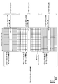
- FIG. 3 is a diagram illustrating an example of an NR downlink subframe according to the present embodiment.
- signals generated using parameter set 1, parameter set 0 and parameter set 2 are FDM in a cell (system bandwidth).
- the diagram shown in FIG. 3 is also referred to as the NR downlink resource grid.
- the base station apparatus 100 can transmit NR downlink physical channels and / or NR downlink physical signals in downlink subframes to the terminal apparatus 200.
- the terminal device 200 can receive the NR downlink physical channel and / or the NR downlink physical signal in the downlink subframe from the base station device 100.
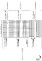
- FIG. 4 is a diagram showing an example of an uplink subframe of NR according to the present embodiment.
- signals generated using parameter set 1, parameter set 0 and parameter set 2 are FDM in a cell (system bandwidth).
- the diagram shown in FIG. 4 is also referred to as NR uplink resource grid.
- the base station apparatus 100 can transmit the NR uplink physical channel and / or the NR uplink physical signal in the uplink subframe to the terminal apparatus 200.
- the terminal device 200 can receive the NR uplink physical channel and / or the NR uplink physical signal in the uplink subframe from the base station device 100.
- physical resources may be defined as follows.
- One slot is defined by a plurality of symbols.
- the physical signal or physical channel transmitted in each of the slots is represented by a resource grid.
- a resource grid is defined by a plurality of subcarriers in the frequency direction and a plurality of OFDM symbols in the time direction.
- the resource grid is defined by multiple subcarriers in the frequency direction and multiple OFDM symbols or SC-FDMA symbols in the time direction.
- the number of subcarriers or resource blocks may depend on the bandwidth of the cell.
- the number of symbols in one slot depends on the type of CP (Cyclic Prefix).
- the type of CP is normal CP or extended CP.
- the number of OFDM symbols or SC-FDMA symbols constituting one slot is seven.
- the number of OFDM symbols or SC-FDMA symbols constituting one slot is six.
- Each of the elements in the resource grid is called a resource element.
- a resource element is identified using a subcarrier index (number) and a symbol index (number).
- an OFDM symbol or SC-FDMA symbol is also simply referred to as a symbol.
- Resource blocks are used to map certain physical channels (such as PDSCH or PUSCH) to resource elements.
- the resource blocks include virtual resource blocks and physical resource blocks. Certain physical channels are mapped to virtual resource blocks. Virtual resource blocks are mapped to physical resource blocks.
- One physical resource block is defined by a predetermined number of consecutive symbols in the time domain.
- One physical resource block is defined from a predetermined number of consecutive subcarriers in the frequency domain. The number of symbols and the number of subcarriers in one physical resource block are determined based on the type of CP in that cell, subcarrier spacing, and / or parameters set by the upper layer, and the like.
- one physical resource block is composed of (7 ⁇ 12) resource elements. Physical resource blocks are numbered from zero in the frequency domain. Also, two resource blocks in one subframe corresponding to the same physical resource block number are defined as physical resource block pairs (PRB pair, RB pair).
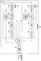
- FIG. 5 is a schematic block diagram showing the configuration of the base station apparatus 100 according to the present embodiment.
- the base station apparatus 100 includes an upper layer processing unit 101, a control unit 103, a receiving unit 105, a transmitting unit 107, and a transmitting / receiving antenna 109.
- the receiving unit 105 is configured to include a decoding unit 1051, a demodulation unit 1053, a demultiplexing unit 1055, a wireless reception unit 1057, and a channel measurement unit 1059.
- the transmission unit 107 includes an encoding unit 1071, a modulation unit 1073, a multiplexing unit 1075, a radio transmission unit 1077, and a downlink reference signal generation unit 1079.
- the base station apparatus 100 can support one or more RATs. Some or all of the units included in the base station apparatus 100 shown in FIG. 5 can be individually configured according to the RAT. For example, the receiving unit 105 and the transmitting unit 107 are individually configured with LTE and NR. Further, in the NR cell, some or all of the units included in the base station apparatus 100 shown in FIG. 5 can be individually configured according to the parameter set related to the transmission signal. For example, in an NR cell, the wireless reception unit 1057 and the wireless transmission unit 1077 can be individually configured according to a parameter set related to a transmission signal.
- the upper layer processing unit 101 includes a Medium Access Control (MAC) layer, a Packet Data Convergence Protocol (PDCP) layer, a Radio Link Control (RLC) layer, and a Radio Resource Control (Radio Resource Control). Resource Control (RRC) layer processing is performed. Also, the upper layer processing unit 101 generates control information to control the receiving unit 105 and the transmitting unit 107, and outputs the control information to the control unit 103.
- MAC Medium Access Control
- PDCP Packet Data Convergence Protocol
- RLC Radio Link Control
- RRC Radio Resource Control
- the control unit 103 controls the receiving unit 105 and the transmitting unit 107 based on the control information from the upper layer processing unit 101.
- the control unit 103 generates control information for the upper layer processing unit 101, and outputs the control information to the upper layer processing unit 101.
- Control section 103 receives the decoded signal from decoding section 1051 and the channel estimation result from channel measurement section 1059.
- the control unit 103 outputs the signal to be encoded to the encoding unit 1071. Also, the control unit 103 is used to control the whole or a part of the base station apparatus 100.
- the upper layer processing unit 101 performs processing and management regarding RAT control, radio resource control, subframe configuration, scheduling control, and / or CSI report control.
- the processing and management in upper layer processing section 101 are performed commonly for each terminal apparatus 200 or commonly for terminal apparatuses 200 connected to base station apparatus 100.
- the processing and management in upper layer processing section 101 may be performed only in upper layer processing section 101, or may be acquired from an upper node or another base station apparatus 100.
- the processing and management in upper layer processing section 101 may be performed individually according to the RAT.
- the upper layer processing unit 101 separately performs processing and management in LTE and processing and management in NR.
- management regarding the RAT is performed.
- management regarding LTE and / or management regarding NR are performed.
- Management regarding NR includes setting and processing of parameter sets regarding transmission signals in NR cells.
- radio resource control in upper layer processing section 101, generation and / or management of downlink data (transport block), system information, RRC message (RRC parameter), and / or MAC control element (CE: Control Element) To be done.
- transport block transport block
- RRC message RRC parameter
- CE MAC control element
- subframe setting in upper layer processing section 101 management of subframe setting, subframe pattern setting, uplink-downlink setting, uplink reference UL-DL setting, and / or downlink reference UL-DL setting is performed. It will be.
- the subframe setting in upper layer processing section 101 is also referred to as base station subframe setting.
- the subframe setting in the upper layer processing unit 101 can be determined based on the uplink traffic volume and the downlink traffic volume.
- the subframe setting in the upper layer processing unit 101 can be determined based on the scheduling result of the scheduling control in the upper layer processing unit 101.
- control unit 103 In scheduling control in upper layer processing section 101, frequencies and subframes to which physical channels are allocated and physical channels based on received channel state information and channel path estimation values and channel quality received from channel measurement section 1059, etc. The coding rate, modulation scheme, transmission power, etc. are determined. For example, the control unit 103 generates control information (DCI format) based on the scheduling result of the scheduling control in the upper layer processing unit 101.
- DCI format control information
- CSI reporting of terminal apparatus 200 is controlled.
- the setting regarding the CSI reference resource for assuming to calculate CSI in the terminal device 200 is controlled.
- the reception unit 105 Under the control of the control unit 103, the reception unit 105 receives a signal transmitted from the terminal device 200 via the transmission / reception antenna 109, and further performs reception processing such as separation, demodulation, decoding, etc. It is output to the control unit 103. In addition, the reception process in the receiving part 105 is performed based on the setting prescribed beforehand or the setting which the base station apparatus 100 notified the terminal device 200.
- the wireless reception unit 1057 performs conversion (down conversion) to an intermediate frequency, removal of unnecessary frequency components, and signal level to be appropriately maintained for the uplink signal received via the transmission / reception antenna 109.
- Control of amplification level, quadrature demodulation based on in-phase and quadrature components of received signal, conversion from analog signal to digital signal, removal of guard interval (GI), and / or fast Fourier transform (Fast Fourier transform) Performs frequency domain signal extraction by Transform: FFT.
- the demultiplexing unit 1055 separates uplink channels and / or uplink reference signals such as PUCCH (Physical Uplink Control Channel) or PUSCH (Physical Uplink shared Channel) from the signal input from the wireless reception unit 1057.
- the demultiplexing unit 1055 outputs the uplink reference signal to the channel measurement unit 1059.
- the demultiplexing unit 1055 performs propagation channel compensation for the uplink channel from the propagation channel estimation value input from the channel measurement unit 1059.
- Demodulation section 1053 is a received signal using a modulation scheme such as Binary Phase Shift Keying (BPSK), Quadrature Phase Shift Keying (QPSK), Quadrature Amplitude Modulation (16 QAM), 64 QAM, 256 QAM or the like for modulation symbols of the uplink channel Demodulate the The demodulation unit 1053 performs separation and demodulation of the MIMO multiplexed uplink channel.
- BPSK Binary Phase Shift Keying
- QPSK Quadrature Phase Shift Keying
- QAM Quadrature Amplitude Modulation
- 64 QAM 64 QAM
- 256 QAM 256 QAM
- the decoding unit 1051 performs a decoding process on the demodulated coded bits of the uplink channel.
- the decoded uplink data and / or uplink control information is output to control section 103.
- the decoding unit 1051 performs decoding processing for each transport block for the PUSCH.
- Channel measuring section 1059 measures an estimated value of the propagation path and / or channel quality from the uplink reference signal input from demultiplexing section 1055, and outputs the measured value to demultiplexing section 1055 and / or control section 103.
- the channel measurement unit 1059 measures an estimated value of a propagation path for performing channel compensation for PUCCH or PUSCH using UL-DMRS, and uses uplink sound quality (SRS) (Sounding Reference Signal) to measure channel quality in uplink. taking measurement.
- SRS Sound quality
- the transmission unit 107 performs transmission processing such as encoding, modulation, and multiplexing on the downlink control information and the downlink data input from the upper layer processing unit 101 according to the control from the control unit 103. For example, the transmission unit 107 generates and multiplexes a PHICH, a PDCCH, an EPDCCH, a PDSCH, and a downlink reference signal to generate a transmission signal. Note that the transmission processing in transmission section 107 is based on settings defined in advance, settings notified to terminal apparatus 200 by base station apparatus 100, or settings notified via PDCCH or EPDCCH transmitted in the same subframe. To be done.
- Coding section 1071 performs predetermined coding such as block coding, convolutional coding, turbo coding, and the like on HARQ indicator (HARQ-ACK), downlink control information, and downlink data input from control section 103. Encoding is performed using a scheme.
- the modulator 1073 modulates the coded bits input from the encoder 1071 according to a predetermined modulation scheme such as BPSK, QPSK, 16 QAM, 64 QAM, 256 QAM, and the like.
- the downlink reference signal generation unit 1079 generates a downlink reference signal based on physical cell identification (PCI), RRC parameters set in the terminal device 200, and the like.
- the multiplexing unit 1075 multiplexes the modulation symbol of each channel and the downlink reference signal, and arranges them in a predetermined resource element.
- the wireless transmission unit 1077 converts the signal from the multiplexing unit 1075 into a time domain signal by Inverse Fast Fourier Transform (IFFT), adds a guard interval, and generates a baseband digital signal. Performs processing such as conversion to analog signal, quadrature modulation, conversion of intermediate frequency signal to high frequency signal (up convert: up convert), removal of extra frequency components, amplification of power, etc. .
- IFFT Inverse Fast Fourier Transform
- the transmission signal output from the wireless transmission unit 1077 is transmitted from the transmission / reception antenna 109.
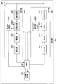
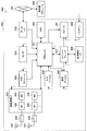
- FIG. 6 is a schematic block diagram showing the configuration of the terminal device 200 according to the present embodiment.
- the terminal device 200 includes an upper layer processing unit 201, a control unit 203, a receiving unit 205, a transmitting unit 207, and a transmitting / receiving antenna 209.
- the receiving unit 205 is configured to include a decoding unit 2051, a demodulation unit 2053, a demultiplexing unit 2055, a wireless reception unit 2057, and a channel measurement unit 2059.
- the transmission unit 207 includes an encoding unit 2071, a modulation unit 2073, a multiplexing unit 2075, a radio transmission unit 2077, and an uplink reference signal generation unit 2079.
- the terminal device 200 can support one or more RATs. Some or all of the units included in the terminal device 200 shown in FIG. 6 may be individually configured according to the RAT. For example, the reception unit 205 and the transmission unit 207 are individually configured with LTE and NR. Also, in the NR cell, some or all of the units included in the terminal device 200 shown in FIG. 6 can be individually configured according to the parameter set related to the transmission signal. For example, in an NR cell, the wireless reception unit 2057 and the wireless transmission unit 2077 can be individually configured according to a parameter set related to a transmission signal.
- Upper layer processing section 201 outputs uplink data (transport block) to control section 203.
- the upper layer processing unit 201 includes a Medium Access Control (MAC) layer, a Packet Data Convergence Protocol (PDCP) layer, a Radio Link Control (RLC) layer, and a Radio Resource Control (Radio Resource Control).
- MAC Medium Access Control
- PDCP Packet Data Convergence Protocol
- RLC Radio Link Control
- RRC Radio Resource Control
- RRC Radio Resource Control
- the upper layer processing unit 201 generates control information to control the receiving unit 205 and the transmitting unit 207, and outputs the control information to the control unit 203.
- the control unit 203 controls the reception unit 205 and the transmission unit 207 based on the control information from the upper layer processing unit 201.
- the control unit 203 generates control information for the upper layer processing unit 201 and outputs the control information to the upper layer processing unit 201.
- the control unit 203 inputs the decoded signal from the decoding unit 2051 and the channel estimation result from the channel measurement unit 2059.
- the control unit 203 outputs the signal to be encoded to the encoding unit 2071.
- the control unit 203 may be used to control the whole or a part of the terminal device 200.
- the upper layer processing unit 201 performs processing and management regarding RAT control, radio resource control, subframe setting, scheduling control, and / or CSI report control.
- the processing and management in upper layer processing section 201 are performed based on settings defined in advance and / or settings based on control information set or notified from base station apparatus 100.
- control information from the base station device 100 includes an RRC parameter, a MAC control element, or a DCI.
- the processing and management in upper layer processing section 201 may be performed individually according to the RAT.
- the upper layer processing unit 201 separately performs processing and management in LTE and processing and management in NR.
- management regarding the RAT is performed.
- management regarding LTE and / or management regarding NR are performed.
- Management regarding NR includes setting and processing of parameter sets regarding transmission signals in NR cells.
- radio resource control in the upper layer processing unit 201 management of setting information in the own apparatus is performed.
- radio resource control in upper layer processing section 201 generation and / or management of uplink data (transport block), system information, RRC message (RRC parameter), and / or MAC control element (CE: Control Element) To be done.
- subframe setting in upper layer processing section 201 subframe setting in base station apparatus 100 different from base station apparatus 100 and / or base station apparatus 100 is managed.
- the subframe configuration includes uplink or downlink configuration for subframes, subframe pattern configuration, uplink-downlink configuration, uplink reference UL-DL configuration, and / or downlink reference UL-DL configuration.
- the subframe setting in upper layer processing section 201 is also referred to as terminal subframe setting.
- control information for performing control related to scheduling for receiving section 205 and transmitting section 207 is generated based on DCI (scheduling information) from base station apparatus 100.
- CSI report control in upper layer processing section 201 control on reporting of CSI to base station apparatus 100 is performed.
- the setting regarding the CSI reference resource to be assumed to calculate CSI in channel measurement section 2059 is controlled.
- resources (timing) used to report CSI are controlled based on DCI and / or RRC parameters.
- the receiving unit 205 Under the control of the control unit 203, the receiving unit 205 receives a signal transmitted from the base station apparatus 100 via the transmission / reception antenna 209, and further performs reception processing such as separation, demodulation, decoding, etc. Are output to the control unit 203. Note that the reception process in the reception unit 205 is performed based on a preset setting or a notification or setting from the base station apparatus 100.
- the wireless reception unit 2057 performs conversion (down conversion) to an intermediate frequency, removal of unnecessary frequency components, and signal level to be appropriately maintained for the uplink signal received via the transmission / reception antenna 209. Control of amplification level, quadrature demodulation based on in-phase and quadrature components of received signal, conversion from analog signal to digital signal, removal of guard interval (GI), and / or fast Fourier transform (Fast Fourier transform) Performs signal extraction in the frequency domain by Transform: FFT.
- FFT fast Fourier transform
- the demultiplexing unit 2055 demultiplexes the downlink channel such as PHICH, PDCCH, EPDCCH, or PDSCH, the downlink synchronization signal, and / or the downlink reference signal from the signal input from the wireless reception unit 2057.
- the demultiplexing unit 2055 outputs the downlink reference signal to the channel measurement unit 2059.
- the demultiplexing unit 2055 performs propagation channel compensation for the downlink channel from the propagation channel estimation value input from the channel measurement unit 2059.
- Demodulation section 2053 demodulates the received signal using a modulation scheme such as BPSK, QPSK, 16 QAM, 64 QAM, 256 QAM or the like on the modulation symbol of the downlink channel.
- Demodulation section 2053 performs separation and demodulation of the MIMO multiplexed downlink channel.
- the decoding unit 2051 performs a decoding process on the demodulated coded bits of the downlink channel.
- the decoded downlink data and / or downlink control information is output to the control unit 203.
- the decoding unit 2051 performs a decoding process for each transport block with respect to the PDSCH.
- the channel measurement unit 2059 measures the estimated value of the propagation path and / or the channel quality from the downlink reference signal input from the demultiplexing unit 2055, and outputs the measured value to the demultiplexing unit 2055 and / or the control unit 203.
- the downlink reference signal used for measurement by the channel measurement unit 2059 may be determined based on at least a transmission mode set by RRC parameters and / or other RRC parameters.
- the DL-DMRS measures channel estimates for performing channel compensation for PDSCH or EPDCCH.
- the CRS measures channel estimates for performing channel compensation for the PDCCH or PDSCH, and / or channels in the downlink for reporting CSI.
- CSI-RS measures the channel in downlink for reporting CSI.
- the channel measurement unit 2059 calculates reference signal received power (RSRP) and / or reference signal received quality (RSRQ) based on CRS, CSI-RS, or the detected signal, and outputs the calculated signal to the upper layer processing unit 201.
- RSRP reference signal received
- the transmission unit 207 performs transmission processing such as encoding, modulation, and multiplexing on the uplink control information and the uplink data input from the upper layer processing unit 201 according to the control from the control unit 203. For example, the transmission unit 207 generates and multiplexes uplink channels and / or uplink reference signals such as PUSCH or PUCCH, and generates a transmission signal. In addition, the transmission process in the transmission part 207 is performed based on the setting prescribed beforehand, or the setting or notification from the base station apparatus 100. FIG.
- Coding section 2071 performs predetermined coding such as block coding, convolutional coding, turbo coding, etc. on the HARQ indicator (HARQ-ACK), uplink control information and uplink data inputted from control section 203. Encoding is performed using a scheme.
- the modulation unit 2073 modulates the coded bits input from the coding unit 2071 according to a predetermined modulation scheme such as BPSK, QPSK, 16 QAM, 64 QAM, or 256 QAM.
- the uplink reference signal generation unit 2079 generates an uplink reference signal based on RRC parameters and the like set in the terminal device 200.
- the multiplexing unit 2075 multiplexes the modulation symbols of each channel and the uplink reference signal, and arranges them in predetermined resource elements.
- the wireless transmission unit 2077 converts the signal from the multiplexing unit 2075 into a time domain signal by Inverse Fast Fourier Transform (IFFT), adds a guard interval, and generates a baseband digital signal. Performs processing such as conversion to analog signal, quadrature modulation, conversion of intermediate frequency signal to high frequency signal (up convert: up convert), removal of extra frequency components, amplification of power, etc. .
- IFFT Inverse Fast Fourier Transform
- the transmission signal output from the wireless transmission unit 2077 is transmitted from the transmission / reception antenna 209.
- the base station apparatus 100 and the terminal apparatus 200 can use various methods for signaling (notification, notification, setting) of control information.
- Signaling of control information can be performed at various layers.
- the signaling of control information includes physical layer signaling that is signaling through a physical layer (layer), RRC signaling that is signaling through an RRC layer, MAC signaling that is signaling through an MAC layer, and the like.
- RRC signaling is dedicated RRC signaling (Dedicated RRC signaling) for notifying the terminal device 200 of unique control information, or common RRC signaling (Common RRC signaling) for notifying the base station device 100 of unique control information.
- Signaling used by upper layers with respect to the physical layer, such as RRC signaling and MAC signaling is also referred to as upper layer signaling.
- RRC signaling is realized by signaling RRC parameters.
- MAC signaling is implemented by signaling a MAC control element.
- Physical layer signaling is realized by signaling downlink control information (DCI) or uplink control information (UCI).
- DCI downlink control information
- UCI uplink control information
- the RRC parameters and the MAC control element are transmitted using PDSCH or PUSCH.
- DCI is transmitted using PDCCH or EPDCCH.
- UCI is transmitted using PUCCH or PUSCH.
- RRC signaling and MAC signaling are used to signal semi-static control information, also called semi-static signaling.
- Physical layer signaling is used to signal dynamic control information, also referred to as dynamic signaling.
- the DCI is used for PDSCH scheduling or PUSCH scheduling.
- the UCI is used for CSI reporting, HARQ-ACK reporting, and / or scheduling request (SR).
- SR scheduling request
- the initial connection is a process of transitioning from a state where the terminal device 200 is not connected to any cell (idle state) to a state where a connection with any cell is established (connected state).
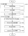
- FIG. 7 is a flowchart showing an example of an initial connection procedure of the terminal device 200 according to the present embodiment.
- the terminal device 200 in an idle state performs a cell selection procedure (step S110).
- the cell selection procedure includes steps of detection of synchronization signal (step S111) and decoding of PBCH (step S112).
- the terminal device 200 performs downlink synchronization with the cell based on the detection of the synchronization signal. Then, after downlink synchronization is established, the terminal device 200 attempts to decode the PBCH and acquires first system information.
- the terminal device 200 acquires second system information based on the first system information included in the PBCH (step S120).
- the terminal device 200 performs a random access procedure (random access procedure, RACH procedure, RACH procedure) based on the first system information and / or the second system information (step S130).
- a random access procedure random access procedure, RACH procedure, RACH procedure
- transmission of random access preamble step S131
- reception of random access response step S132
- transmission of message 3 message 3)
- reception of collision resolution step S133
- Step S134 is included.
- the terminal device 200 first selects a predetermined PRACH preamble and performs transmission.
- the terminal device 200 receives a PDSCH including a random access response corresponding to the transmitted PRACH preamble.
- the terminal device 200 transmits the PUSCH including the message 3 using the resource scheduled by the random access response grant included in the received random access response.
- the terminal device 200 receives a PDSCH including collision resolution corresponding to that PUSCH.
- Message 3 includes an RRC message of RRC connection request.
- the collision resolution includes an RRC message of RRC connection setup.
- the terminal device 200 When receiving the RRC message of RRC connection setup, the terminal device 200 performs RRC connection operation, and transitions from the RRC idle state to the RRC connected state. After transitioning to the RRC connection state, the terminal device 200 transmits an RRC message of RRC connection setup completion to the base station device 100.
- the terminal device 200 can be connected to the base station device 100 by this series of operations.
- the random access preamble is also referred to as message 1, random access response as message 2, collision resolution as message 4, and the message of RRC connection setup completion as message 5.
- the terminal device 200 can transition to a state (connected state) connected to the cell.
- the random access procedure shown in FIG. 7 is also referred to as a four-step RACH procedure.
- the random access procedure in which the terminal device 200 also transmits Message 3 along with the transmission of random access preambles and the base station device 100 transmits a random access response and Contention resolution as their response is a two-step RACH procedure. It is called.
- the random access preamble is transmitted in association with the PRACH.
- the random access response is sent on PDSCH.
- the PDSCH including the random access response is scheduled on the PDCCH.
- Message 3 is sent on PUSCH.
- the PUSCH including the message 3 is scheduled by the uplink grant included in the random access response.
- System information is information that broadcasts settings in a cell that transmits the system information.
- the system information includes, for example, information on access to the cell, information on cell selection, information on other RATs and other systems, and the like.
- System information can be classified into a master information block (MIB) and a system information block (SIB).
- MIB is information of a fixed payload size broadcasted by PBCH.
- the MIB contains information for acquiring the SIB.
- the SIB is system information other than the MIB.
- the SIB is broadcasted by the PDSCH.
- system information can be classified into first system information, second system information, and third system information.
- the first system information and the second system information include information on access to the cell, information on acquisition of other system information, and information on cell selection.
- LTE it can be considered that the information contained in MIB is the first system information
- SIB1 and SIB2 is the second system information. If the terminal device can not acquire all of the first system information and the second system information from the cell, it is assumed that access to the cell is prohibited.
- the MIB is physical layer information necessary to receive system information, and includes downlink system bandwidth, part of a system frame number, scheduling information of SIB, and the like.
- SIB1 is cell access control information and scheduling information of system information other than SIB1, and cell access information, cell selection information, maximum uplink transmission power information, TDD configuration information, system information cycle, and system information mapping information , SI window length, etc. are included.
- the SIB 2 includes connection prohibition information, common radio resource configuration information (radioResourceConfigCommon), uplink carrier information, and the like.
- the cell common radio resource setting information includes cell common PRACH and RACH setting information.
- System information of NR is broadcasted from the NR cell.
- the physical channel carrying system information may be transmitted in slots or minislots.
- a minislot is defined by the number of symbols smaller than the number of symbols in the slot.
- the first system information is sent on the NR-PBCH, and the second system information is sent on a different physical channel than the NR-PBCH.
- the RACH procedure performs RRC connection setup from idle state to inactive state or connected state, request for state transition from inactive state to connected state, handover to switch connected cell, and resource request for uplink data transmission. This is done to achieve the objectives such as request, timing advance adjustment to adjust uplink synchronization, on-demand SI request to request unsent system information, return of broken beam connection (beam recovery), etc.
- the RRC connection setup from the idle state to the inactive state or the connected state is an operation performed when the terminal device 200 connects with the base station device 100 in response to the occurrence of traffic or the like. Specifically, it is an operation of passing information (for example, UE context) related to connection from the base station apparatus 100 to the terminal apparatus 200.
- the UE context is managed by predetermined terminal device identification information (for example, C-RNTI) instructed from the base station device 100.
- C-RNTI terminal device identification information
- the request for state transition from the inactive state to the connected state is an operation for requesting the state transition from the inactive state to the connected state in response to the occurrence of traffic or the like.
- the terminal device 200 can transmit and receive unicast data with the base station device 100.
- the handover for switching the connection cell is an operation for switching the connection from a cell (serving) connected to a cell adjacent to the cell (neighboring cell) due to a change in radio environment such as movement of the terminal device 200.
- the terminal device 200 that has received the handover command from the base station device 100 makes a connection request to the neighbor cell specified by the handover command.
- the scheduling request is an operation of making a resource request for uplink data transmission in response to the occurrence of traffic or the like.
- the base station apparatus 100 allocates the PUSCH resource to the terminal apparatus 200 after successfully receiving this scheduling request.
- the scheduling request is also made by the PUCCH.
- Timing advance adjustment for adjusting uplink synchronization is an operation for adjusting an error in downlink and uplink frames caused by propagation delay.
- the terminal device 200 transmits the PRACH at the timing adjusted to the downlink frame.
- the base station apparatus 100 can recognize the propagation delay with the terminal apparatus 200, and can instruct the terminal apparatus 200 the value of timing advance using message 2 or the like.
- the broken beam connection recovery is an operation to make a recovery request when the communication quality is degraded due to the movement of the terminal 200 or the blocking of the communication path by another object after the beam is established. .
- the base station apparatus 100 that has received this request tries to connect with the terminal apparatus 200 using different beams.
- the RACH procedure further includes a collision based RACH procedure and a non-collision RACH procedure.
- the collision based RACH procedure is a RACH procedure that is performed by the terminal device 200.
- the collision based RACH procedure is a four-step procedure starting with the transmission of message 1 from the terminal device 200.
- the terminal device 200 selects a plurality of RACH resources and a plurality of PRACH preambles set in advance, and transmits the PRACH. Since the plurality of RACH resources and the plurality of PRACH preambles are shared with other terminal apparatuses 200, the PRACH may collide.
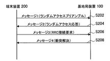
- FIG. 8 is a sequence diagram showing an example of the flow of a collision based RACH procedure according to the present embodiment.
- the terminal device 200 transmits a random access preamble also referred to as message 1 to the base station device 100 (step S202).
- the base station apparatus 100 transmits a random access response, also referred to as message 2, to the terminal apparatus 200 (step S204).
- the terminal device 200 transmits, to the base station device 100, an RRC message of RRC connection request, which is also referred to as message 3 (step S206).
- the base station apparatus 100 transmits, to the terminal apparatus 200, the collision resolution also referred to as the message 4 (step S208).
- the non-collision RACH procedure is a RACH procedure performed mainly by the base station apparatus 100.
- the non-collision RACH procedure is a total of three steps starting from the transmission of the PDCCH order from the base station apparatus 100.
- the terminal device 200 transmits a random access preamble using the PRACH indicated in the PDCCH order.
- the base station apparatus 100 scheduling a random access preamble makes it difficult for the PRACH to collide.
- FIG. 9 is a sequence diagram showing an example of the flow of the non-collision RACH procedure according to the present embodiment.
- the base station apparatus 100 transmits a PDCCH order to the terminal apparatus 200 (step S302).
- the terminal device 200 transmits a random access preamble to the base station device 100 (step S304).
- the base station apparatus 100 transmits a random access response to the terminal apparatus 200 (step S306).
- the NR-PRACH is configured using a Zadoff-Chu sequence or an M sequence.
- a plurality of preamble formats are defined.
- the preamble format is defined by a combination of parameters such as PRACH subcarrier interval, transmission bandwidth, sequence length, number of symbols used for transmission, transmission repetition number, CP length, guard period length, and the like.
- the type of sequence (Zadoff-Chu sequence or M sequence) used for transmission of the NR-PRACH may be designated by the preamble format.
- setting relating to the NR-PRACH is performed by system information. Furthermore, for the terminal device 200 in the connection mode, settings relating to the NR-PRACH are performed by dedicated RRC signaling.
- the NR-PRACH is transmitted by a physical resource (NR-PRACH occasion) that can be transmitted by the NR-PRACH.
- the physical resource is indicated by the setting for NR-PRACH.
- the terminal device 200 selects one of the physical resources and transmits an NR-PRACH. Furthermore, the terminal device 200 in the connection mode transmits an NR-PRACH using an NR-PRACH resource.
- the NR-PRACH resource is a combination of the NR-PRACH preamble and its physical resources.
- the base station apparatus 100 can indicate the NR-PRACH resource to the terminal apparatus 200.
- the sequence types of the NR-PRACH preamble are numbered.
- the sequence type number of the preamble is called a preamble index.
- the NR-PRACH is retransmitted when the random access procedure fails.
- the terminal device 200 stands by for transmission of the NR-PRACH for a standby period calculated from the value of backoff (backoff indicator, BI).
- the backoff value may differ depending on the terminal category of the terminal device 200 and the priority of the generated traffic. At that time, a plurality of backoff values are notified, and the terminal device 200 selects a backoff value to be used according to the priority.
- the transmission power of the NR-PRACH is increased relative to the initial transmission (this procedure is called power ramping).
- the NR random access response is sent by the NR-PDSCH.
- the NR-PDSCH including the random access response is scheduled by the NR-PDCCH in which the CRC is scrambled by the RA-RNTI.
- the NR-PDCCH is transmitted on a common control subband.
- the NR-PDCCH is arranged in a CSS (Common Search Space).
- the value of RA-RNTI is determined based on the transmission resource (time resource (slot or subframe) and frequency resource (resource block)) of NR-PRACH corresponding to the random access response.
- the NR-PDCCH may be arranged in a search space associated with the NR-PRACH associated with the random access response.
- the search space in which the NR-PDCCH is arranged is set in association with the NR-PRACH preamble and / or the physical resource to which the NR-PRACH is transmitted.
- the search space in which the NR-PDCCH is allocated is set in association with the preamble index and / or the index of the physical resource.
- the NR-PDCCH is NR-SS and QCL.
- the NR random access response is MAC information.
- the NR random access response includes at least an uplink grant for transmitting message 3 of NR, a value of timing advance used to adjust uplink frame synchronization, and a value of temporary C-RNTI.
- the NR random access response includes the PRACH index used for NR-PRACH transmission corresponding to the random access response.
- the NR random access response includes information on backoff used for waiting for PRACH transmission.
- the base station apparatus 100 transmits the NR-PDSCH, including these pieces of information. From these pieces of information, the terminal device 200 determines whether transmission of the random access preamble is successful.
- the terminal device 200 If it is determined from this information that the transmission of the random access preamble has failed, the terminal device 200 performs the process of transmitting the NR message 3 in accordance with the information included in the random access response. On the other hand, when it is determined that the transmission of the random access preamble has failed, the terminal device 200 considers that the random access procedure has failed and performs retransmission processing of the NR-PRACH.
- a plurality of uplink grants for transmitting the NR message 3 may be included in the NR random access response.
- the terminal device 200 can select one resource for transmitting the message 3 from the plurality of uplink grants. As a result, when different terminal devices 200 receive the same NR random access response, it is possible to alleviate the collision of NR message 3 transmission, and a more stable random access procedure can be provided.
- the NR message 3 is sent by the NR-PUSCH.
- the NR-PUSCH is sent using the resources indicated by the random access response.
- the NR message 3 includes an RRC connection request message.
- the waveform of the NR-PUSCH transmitted including the NR message 3 is indicated by the parameters contained in the system information. Specifically, OFDM or DFT-s-OFDM is determined according to the indication of the parameter.
- the base station device 100 When the base station device 100 receives the NR message 3 normally, the base station device 100 shifts to a collision resolution transmission process. On the other hand, when the base station apparatus 100 can not receive the NR message 3 normally, it can try to receive the NR message 3 again at least for a predetermined period.
- the base station apparatus 100 instructs the terminal apparatus 200 to retransmit the message 3 as a specific example of the process after the NR message 3 can not be normally received.
- the base station apparatus 100 transmits an instruction to resend message 3 using a downlink resource after a predetermined number of slots (or subframes, radio frames) from the resource instructed to transmit message 3.
- an indication by retransmission of the random access response may be mentioned.
- the NR-PDSCH including the retransmitted random access response is scheduled by the NR-PDCCH in which the CRC is scrambled by the RA-RNTI.
- the value of RA-RNTI is the same as the value of RA-RNTI used in the first transmission. That is, it is determined based on the transmission resource of NR-PRACH corresponding to the random access response. Alternatively, the value of RA-RNTI may be determined based on information identifying the initial transmission and retransmission in addition to the transmission resource of NR-PRACH.
- the NR-PDCCH is arranged in a CSS (Common Search Space).
- the NR-PDSCH including the retransmitted random access response is scheduled by the NR-PDCCH scrambled with CRC by the temporary C-RNTI or C-RNTI included in the random access response transmitted in the first transmission.
- an indication by NR-PDCCH used for indication of retransmission of message 3 can be mentioned.
- the NR-PDCCH is an uplink grant.
- the resource of message 3 retransmission is indicated by the DCI of the NR-PDCCH.
- the terminal device 200 retransmits the message 3 based on the indication of the uplink grant.
- the base station apparatus 100 attempts to receive the message 3 in the retransmission resource instructed in advance.
- the terminal device 200 transmits the NR-PUSCH including the message 3 using the resource for retransmission instructed in advance. Do.
- the terminal device 200 when the terminal device 200 receives a NACK for the message 3, the terminal device 200 transmits an NR-PUSCH including the message 3 using a resource for retransmission designated in advance corresponding to the NACK.
- the resource for retransmission instructed in advance is included in, for example, system information or a random access response.
- the terminal device 200 If the number of retransmissions of the NR message 3 exceeds a predetermined number, or if the reception of the NR collision resolution is not successful within a predetermined period, the terminal device 200 considers that the random access procedure has failed. , NR-PRACH retransmission processing is performed.
- the transmission beam of the terminal device 200 used for retransmission of the NR message 3 may be different from the transmission beam of the terminal device 200 used for the first transmission of the message 3.
- terminal apparatus 200 If neither the collision resolution of NR nor the instruction to retransmit message 3 can be received within a predetermined period, terminal apparatus 200 considers that the random access procedure has failed and performs retransmission processing of NR-PRACH.
- the predetermined period is set, for example, by system information.
- NR collision resolution is sent by the NR-PDSCH.
- the NR-PDSCH including collision resolution is scheduled by NR-PDCCH in which CRC is scrambled by temporary C-RNTI or C-RNTI.
- the NR-PDCCH is transmitted on a common control subband.
- the NR-PDCCH is allocated to USS (UE-specific search space). Note that the NR-PDCCH may be arranged in the CSS.
- the terminal device 200 When the terminal device 200 normally receives the NR-PDSCH including collision resolution, the terminal device 200 returns an ACK to the base station device 100. Thereafter, the terminal device 200 is in a connected state, assuming that the random access procedure is successful. On the other hand, when a NACK for the NR-PDSCH including collision resolution is received from the terminal apparatus 200 or no response is received, the base station apparatus 100 retransmits the NR-PDSCH including the collision resolution. Furthermore, if the NR collision resolution can not be received within a predetermined period, the terminal device 200 considers that the random access procedure has failed and performs NR-PRACH retransmission processing.
- FIG. 10 is a diagram for explaining an example of uplink synchronization adjustment according to the present embodiment.
- the terminal device 200A is located near the base station device 100 in the cell 90 provided by the base station device 100, and the terminal device 200B is located far from the base station device 100. It is assumed that these terminal devices 200 simultaneously perform uplink communication.
- each uplink signal is a base station due to different propagation delay and processing delay specific to the terminal device 200. It is received by the apparatus 100 at different reception timings. If the reception timing of each uplink signal is different, inter-symbol interference may occur and the characteristics may be degraded.
- the transmission timing of the uplink signal of the terminal device 200 is adjusted in advance so that the transmission timing of the downlink signal of the base station device 100 and the reception timing of the uplink signal are aligned.
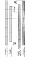
- FIG. 11 is a diagram for explaining an example of uplink synchronization adjustment according to the present embodiment.
- the downlink transmission timing of the base station apparatus 100 is shown in the first stage from the top, and the downlink reception timing of the terminal apparatus 200 is shown in the second stage from the top.
- the uplink transmission timing of the terminal device 200 is shown in the third stage from the top, and the uplink reception timing of the base station apparatus 100 is shown in the fourth stage from the top.
- Each row consists of a plurality of rectangles, and one rectangle indicates one radio frame.
- the downlink signal from the base station apparatus 100 is received by the terminal apparatus 200 with a predetermined time delay due to the influence of the propagation delay and the processing delay of the terminal apparatus 200.
- the terminal device 200 adjusts the uplink transmission timing using the timing advance value instructed from the base station device 100 on the basis of the timing at which the downlink signal is received. Specifically, as shown in the third stage, the terminal device 200 transmits the uplink physical signal by advancing the timing advance value by the timing at which the corresponding downlink signal is received. Thereby, as shown in the fourth stage, the adjusted uplink signal of the terminal device 200 is received by the base station device 100 at the same timing as the downlink transmission timing.
- the timing advance value is calculated as approximately twice the one-way delay time.
- the timing advance value is specific to the terminal device 200.
- the timing advance value is uniquely notified to the terminal device 200.
- the PRACH is used to calculate the timing advance value.
- a random access response (RAR) is used for notification of the timing advance value.
- FIG. 12 is a sequence diagram showing an example of the flow of the uplink synchronization adjustment procedure according to the present embodiment.
- the base station apparatus 100 transmits downlink synchronization signals (PSS (primary synchronization signal) and SSS (secondary synchronization signal)) to the terminal apparatus 200 (step S402).
- PSS primary synchronization signal
- SSS secondary synchronization signal
- the terminal device 200 performs downlink synchronization based on the downlink synchronization signal transmitted from the base station device 100 (step S404).
- the base station apparatus 100 transmits system information (MIB and SIB) (step S406).
- the terminal device 200 receives system information, and acquires a RACH setting from the received system information (step S408).
- MIB and SIB system information
- terminal apparatus 200 transmits PRACH based on the frame timing synchronized by the downlink synchronization signal (step S410).
- the base station apparatus 100 calculates the propagation delay and the timing advance value based on the difference between the reception timing of the PRACH and the timing of the uplink frame of the base station apparatus 100 (step S412).
- the base station apparatus 100 transmits a random access response (RAR) including the timing advance value to the terminal apparatus 200 (step S414).
- RAR random access response
- the terminal device 200 acquires a timing advance value from the received RAR, and adjusts the uplink transmission timing to move forward (step S416).
- the terminal device 200 transmits uplink physical channels / signals such as PUSCH, PUCCH and SRS at the uplink transmission timing adjusted in step S416 (step S418).
- Non-terrestrial network In cellular mobile communication, cells (macro cells, micro cells, femto cells, or small cells) are configured from base station devices or relay devices (hereinafter referred to as ground station devices) installed on the ground to configure a wireless network. .
- the radio network provided by this ground station is called a Terrestrial Network.
- satellite station equipment satellite base station equipment, satellite relay station equipment, space station
- satellite station equipment orbiting the earth because of the cost reduction of the base station equipment and the provision of coverage to difficult areas where radio waves reach from the base station equipment.
- a wireless network provided from other than this ground station apparatus is called a non-terrestrial network.
- the non-ground station apparatus includes a satellite station apparatus and an air station apparatus.
- the satellite station apparatus is an apparatus having a wireless communication function, which is configured as an apparatus such as a satellite for floating outside the atmosphere.
- the satellite station apparatus according to the present embodiment is a low orbit (LEO, Low Earth Orbiting) satellite, a medium orbit (MEO, Medium Earth Orbiting) satellite, a geostationary (GEO, Geostationary Earth Orbiting) satellite, or a high elliptical orbit (HEO, Highly) Elliptical Orbiting satellites and the like.
- the air station apparatus is an apparatus having a wireless communication function, which is configured as an apparatus suspended in the atmosphere such as an aircraft or a balloon.
- the air station apparatus includes an unmanned air system (UAS, Unmanned Aircraft Systems), a tethered unmanned air system (tethered UAS), a light unmanned air system (Lighter than Air UAS, LTA), and a heavy unmanned air system (Heavier than). It may be configured by Air UAS, HTA), or High Altitude UAS Platforms (HAPs) or the like.
- UAS Unmanned Aircraft Systems
- tethered UAS tethered unmanned air system
- LTA light unmanned air system
- Heavier than Heavier than
- It may be configured by Air UAS, HTA), or High Altitude UAS Platforms (HAPs) or the like.
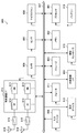
- FIG. 13 is a diagram showing an example of the non-terrestrial wave network according to the present embodiment.
- the system 1 shown in FIG. 13 includes a satellite station device 10A configured as a geostationary satellite, satellite station devices 10B to 10D configured as low orbit satellites, and an air station device 20 configured as an unmanned aerial system. Wave network.
- the satellite station apparatus 10 and the air station apparatus 20 are connected to an apparatus provided on the ground via the relay station 30.
- the satellite station apparatus 10 and the aviation station apparatus 20 are connected to the core network 31 via the relay station 30A, and connected to the Internet 32 and the terrestrial network 33 via the core network 31.
- the satellite station apparatuses 10A and 10B are also connected to the femtocell base station 40A that provides the femtocell via the relay station 30B.
- the relay station 30 is also referred to as an earth station (Very Small Aperture Terminal: VSAT), and may also be referred to as a control earth station or a HUB station.
- VSAT Very Small Aperture Terminal
- the satellite station device 10 and the air station device 20 may be directly connected to a device provided on the ground, not via the VSAT 30.
- the satellite station device 10B and the air station device 20 are directly connected to the macrocell base station 40B.
- the satellite station apparatus 10 and the air station apparatus 20 communicate with a terminal device (also referred to as an earth terminal device) 40 corresponding to a non-terrestrial wave network.
- the earth terminal device 40 includes a mobile phone, a smartphone, a car, a bus, a train, an aircraft, an M2M (Machine to Machine) device, an IoT (Internet of Things) device, a relay station relaying satellite communication, and a base station transmitting and receiving satellite communication. Includes the device.
- the macrocell base station 40 B and the UE 40 C correspond to the earth terminal device 40.
- a femtocell base station 40A connected to a non-terrestrial network via a relay by VSAT 30B and a UE 40D connected to a non-terrestrial network via a relay by UE 40C are also regarded as earth terminal apparatuses 40 corresponding to the non-terrestrial network May be
- the satellite station device 10 and the air station device 20 can transmit and receive uplink traffic and downlink traffic to and from the earth terminal device 40.
- the satellite station devices 10A and 10B and the air station device 20 transmit and receive uplink traffic and downlink traffic with the UE 40C.
- the satellite station apparatus 10 and the air station apparatus 20 can transmit and receive backhaul traffic (in other words, backhaul signals) with the earth terminal apparatus 40.
- the satellite station apparatuses 10A and 10B transmit and receive backhaul traffic for communication performed between the femtocell base station 40A and the UE 40C with the femtocell base station 40A via the VSAT 30B.
- the satellite station apparatus 10B and the air station apparatus 20 directly transmit and receive backhaul traffic for communication between the macrocell base station 40B and the UE 40C with the macrocell base station 40B.
- the satellite communication according to the present embodiment refers to communication between the satellite station device 10 and the earth terminal device 40.
- the satellite station device 10 is divided into a geostationary satellite station device mainly composed of geostationary satellites and a low orbit satellite station device composed of low orbit satellites.
- a geostationary satellite station located at an altitude of approximately 35786 km, orbits the earth at the same speed as the earth's rotation speed.
- the geostationary satellite station device is a satellite station device which has a relative velocity to the earth terminal device 40 substantially zero, and is observed from the earth terminal device 40 as if it were stationary.
- Low orbit satellite stations are generally located between 500 km and 2000 km, and orbit the earth at a lower altitude than geostationary satellite stations.
- the low orbit satellite station device has a relative velocity with the earth terminal device 40 and is observed as if it is moving from the earth terminal device 40.
- the satellite station apparatus 10 can provide a cell of a size corresponding to the height. This point will be described with reference to FIG.
- FIG. 14 is a diagram for explaining an example of a cell provided by the satellite station device 10 according to the present embodiment.
- the satellite station apparatus 10A shown in FIG. 14 is a geostationary satellite station apparatus, and the satellite station apparatuses 10B and 10C are low orbit satellite station apparatuses.
- the low orbit satellite station devices 10B and 10C provide larger cells 90B and 10C than the cell 90D provided by the macro cell base station 40B on the ground.
- the geostationary satellite station device 10A provides a larger cell 90A than the cells 90B and 10C provided by the low orbit satellite station devices 10B and 10C.
- the larger the cell the larger the difference in distance to the satellite station device 10 among the plurality of earth terminal devices 40 located in the cell, and as a result, the difference in propagation delay becomes larger. Further, as the altitude is higher, the distance between the satellite station apparatus 10 and the earth terminal apparatus 40 is longer, so that the propagation delay is longer.
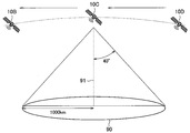
- FIG. 15 is a diagram for explaining an example of a cell provided by the low orbit satellite station apparatus according to the present embodiment.
- the low orbit satellite station devices 10B, 10C, and 10D revolve on the low orbit. These low orbit satellite station devices 10 construct predetermined directivity toward the ground and provide satellite communications to the earth terminal device 40.
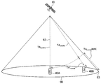
- the low orbit satellite station apparatus 10 transmits and receives signals with the beam width angle of 40 degrees, and as a result, the cell 90 becomes a circle with a radius of 1000 km.
- the beam width angle is a direction in which the directivity gain is half of the maximum directivity gain based on the direction (vertical line 91 in the example shown in FIG. 15) where the maximum directivity gain can be obtained. It is defined as an angle.
- the low orbit satellite station device 10 moves at a predetermined relative speed with respect to the ground. Therefore, the cell 90 provided by the low orbit satellite station device 10 moves on the ground at a predetermined speed. When it becomes difficult to provide satellite communication to the earth terminal device 40, satellite communication is provided from a subsequent lower satellite (neighbor satellite station).
- -Service extension to terminals mainly IoT / MTC devices and public safety / critical communication
- terminals located in areas that can not be covered by terrestrial networks
- connectivity • Service connection and provision to aircraft terminals such as plane passengers or drones • Service connection and provision to mobile terminals such as ships or trains • A / V (audio / visual) content, group communication
- IoT broadcast services software downloads, and emergency messages-Traffic offload between terrestrial and non-terrestrial networks
- non-terrestrial networks In order to meet these requirements, it is desirable for non-terrestrial networks to realize commonality of radio interface with higher layer operation integration and radio access technologies such as NR or LTE.
- the timing advance value is derived by the following equation (1).
- TA (N TA + N TA offset ) T S (1)
- TA is a timing advance value.
- N TA is a variable number for adjusting the timing advance value.
- N TA can take a value of 0 or more and 20 512 or less (that is, 0 ⁇ N TA ⁇ 20512).
- N TAoffset is an offset for adjusting the timing advance value.
- TA is the may take the following values 20512 ⁇ Ts (i.e., 0 ⁇ TA ⁇ 20512 ⁇ Ts ). In other words, TA can take a value of 0 ms or more and 0.67 ms (that is, 0 ms ⁇ TA ⁇ 0.67 ms).
- the range of the timing advance value is set to correspond to the minimum value and the maximum value of the propagation delay difference that can occur in the cell.
- the propagation delay difference between the terminal apparatus and the base station apparatus becomes the minimum value when the terminal apparatus exists at the same point as the base station apparatus, and the terminal apparatus is at the cell edge. It will be the maximum value if it exists.
- the range of the timing advance value for uplink transmission is sufficient with the above-mentioned range (0 ⁇ TA ⁇ 20512 ⁇ Ts, that is, 0 ms ⁇ TA ⁇ 0.67 ms).
- the distance between the satellite station apparatus and the earth terminal apparatus is significantly increased as compared to the case of LTE. Therefore, the minimum propagation delay and the maximum propagation delay involved in the communication between the satellite station apparatus and the earth terminal apparatus are significantly increased as compared with the case of LTE.
- the minimum propagation delay is a propagation delay when the earth terminal device is located directly below (that is, a vertical line) the satellite station device.
- the altitude of the satellite station device is 500 km to 2000 km, and the minimum propagation delay at each altitude is in the range of 3.3 ms to 13.3 ms.
- the maximum propagation delay is the propagation delay when the earth terminal device is located at the cell edge of the satellite station device.
- the altitude of the satellite station device is 500 km to 2000 km
- the maximum propagation delay in the low orbit satellite cell using the parameters of FIG. 15 at each altitude is 4.35 ms to 17 It is in the range of .4 ms.
- the maximum propagation distance is obtained by the following equation (3).
- (Maximum propagation distance) ((altitude of satellite station ⁇ 2 + cell radius ⁇ 2) (3)
- the maximum propagation distance at each altitude is approximately 652.7 to 2610.8 km.
- the propagation delay of 3.3 ms to 17.4 ms be compensated by the timing advance. Furthermore, it is desirable that the larger propagation delay be compensated for by the timing advance, since the geostationary satellite has a higher altitude of 35,786 km and a larger propagation delay.
- the range of timing advance value in LTE could not sufficiently compensate for propagation delay in satellite communication. Therefore, it is difficult to synchronize the transmission from the earth terminal device to the satellite station device in satellite communication.
- the present disclosure provides a mechanism capable of sufficiently compensating for propagation delay in satellite communication.
- FIG. 16 is a diagram for explaining an example of a functional configuration of the satellite station device 10 according to the present embodiment.
- the satellite station apparatus 10 according to the present embodiment includes a setting unit 11 and a message transmission / reception unit 13.
- Each component shown in FIG. 16 can be implemented in any component such as upper layer processing unit 101 or control unit 103 shown in FIG. 5. That is, in the present embodiment, the base station apparatus 100 shown in FIG. 5 is configured as the satellite station apparatus 10.
- the setting unit 11 has a function of generating setting information on transmission parameters used for transmission of a channel / signal from the earth terminal device 40 to the satellite station device 10. Specifically, the setting unit 11 generates satellite station apparatus related information described later. At least a part of the satellite station apparatus related information (for example, orbit information described later) is set or stored in advance in the satellite station apparatus 10. The setting unit 11 transmits the generated satellite station apparatus related information to the earth terminal apparatus 40.
- the message transmission / reception unit 13 has a function of transmitting / receiving a message to / from the earth terminal device 40 based on the setting by the setting unit 11. Specifically, the message transmitting / receiving unit 13 receives the channel / signal transmitted by the earth terminal apparatus 40 using the transmission parameter based on the satellite station apparatus related information. At that time, the message transmission / reception unit 13 receives using the reception parameter corresponding to the transmission parameter used for the earth terminal device 40. For example, the message transmission / reception unit 13 performs reception processing according to the setting of the timing advance and / or the setting of the CP used by the earth terminal device 40.
- FIG. 17 is a view for explaining an example of the functional configuration of the earth terminal device 40 according to the present embodiment.
- the earth terminal apparatus 40 according to the present embodiment includes a setting unit 41 and a message transmitting / receiving unit 43.
- Each component shown in FIG. 17 can be implemented in any component such as upper layer processing unit 201 or control unit 203 shown in FIG. That is, in the present embodiment, the terminal device 200 shown in FIG. 6 is configured as the earth terminal device 40.
- the setting unit 41 has a function of setting transmission parameters used for transmission of channels / signals from the earth terminal device 40 to the satellite station device 10 based on setting information received from the satellite station device 10. Specifically, the setting unit 41 performs setting of timing advance and / or setting of CP based on the satellite station apparatus related information.
- the message transmission / reception unit 43 has a function of transmitting / receiving a message to / from the satellite station apparatus 10 based on the setting by the setting unit 41. Specifically, the message transmitting / receiving unit 43 transmits a channel / signal to the satellite station apparatus 10 using the set transmission parameter.
- the channel / signal transmitted from the satellite station apparatus 10 to the earth terminal apparatus 40 may be a downlink signal (downlink physical channel or downlink physical signal) or backhaul traffic. May be Similarly, the channel / signal transmitted from the earth terminal apparatus 40 to the satellite station apparatus 10 may be an uplink signal (uplink physical channel or uplink physical signal) or may be backhaul traffic. . In the following, for simplicity of explanation, the channel / signal transmitted from the satellite station apparatus 10 to the earth terminal apparatus 40 is a downlink signal, and the channel / signal transmitted from the earth terminal apparatus 40 to the satellite station apparatus 10 is , And uplink signals.
- the satellite station device 10 transmits or notifies the earth terminal device 40 of information on the type of the satellite station device 10. Then, the earth terminal device 40 acquires information on the type of the satellite station device 10, and controls the transmission timing of the signal to the earth terminal device 40 based on the information on the type of the earth terminal device 40. As a result, the earth terminal device 40 can transmit the uplink signal at the transmission timing based on the type of the satellite station device 10. Therefore, it is possible to sufficiently compensate for the propagation delay in satellite communication.
- the information on the type of the satellite station device 10 is also referred to as satellite station device related information.
- the satellite station device related information may include information on the altitude of the satellite station device 10.
- the altitude of the satellite station device 10 greatly affects the propagation delay between the satellite station device 10 and the earth terminal device 40 in the cell. Therefore, the earth terminal device 40 controls transmission timing to compensate for a propagation delay occurring in communication with the satellite station device 10 by notifying the earth terminal device 40 of information on the altitude of the satellite station device 10 It becomes possible.
- Information regarding the altitude of the satellite station device 10 may be provided in various forms.
- the information on the altitude of the satellite station apparatus 10 may be provided as information indicating the range of altitude in which the satellite station apparatus 10 can be located.
- the information on the altitude of the satellite station device 10 may be provided as information indicating the altitude of the satellite station device 10.
- information indicating the altitude of the satellite station apparatus 10 may be provided as orbit information.
- the orbit information includes at least information indicating the altitude of the satellite station device 10.
- orbit information of the low orbit satellite station apparatus is shown in Table 1 below.
- the number of orbits, the number of satellite station devices, the altitude, and the angle are shown.
- the number of trajectories in Table 1 indicates the number of trajectories of the same altitude and angle.
- the number of satellite station devices in Table 1 indicates the number of satellite station devices 10 orbiting at the same altitude and angle.
- the altitudes in Table 1 are orbital altitudes.
- the trajectory information includes information indicating a change in altitude.
- the satellite station device 10 orbits at a speed according to the altitude. That is, it can be said that the altitude included in the orbit information is information indicating the moving speed of the satellite station device 10.
- the orbit information may separately include the moving speed of the satellite station apparatus 10 itself in addition to the altitude.
- the angle in Table 1 is the angle of the trajectory relative to the latitude or longitude. That is, it can be said that the angle included in the orbit information is information indicating the moving direction of the satellite station device 10.
- the satellite station apparatus related information may include various other information. An example will be described below. The information described below can also be grasped as information on the altitude of the satellite station apparatus 10.
- the satellite station apparatus related information may include information indicating whether or not it is a satellite cell. This information may be 1-bit information indicating whether the satellite station apparatus 10 provides a satellite cell.
- the satellite station apparatus related information may include information indicating the type of the satellite station apparatus 10. Such information is information indicating a ground station, low orbit satellites, medium orbit satellites, high orbit satellites, or geostationary satellites.
- the satellite station apparatus related information may include information indicating the maximum coverage (eg, cell radius, beam width or beam angle of a beam used by the satellite station) of the satellite station apparatus 10.
- the satellite station apparatus related information may include information indicating a control method of transmission timing (for example, a range of timing advance value to be described later, adjustment granularity, replacement rule, TA satelite, etc.).
- a control method of transmission timing for example, a range of timing advance value to be described later, adjustment granularity, replacement rule, TA satelite, etc.
- the satellite station apparatus related information may include information indicating a control method of CP length (for example, CP length, etc.).
- the satellite station apparatus related information may include information related to filtering (for example, information indicating a predetermined waveform, filter information (filtering function, roll-off value, etc.), etc.).
- satellite station apparatus related information is broadcast from the satellite station apparatus 10 to the earth terminal apparatus 40 in the cell using, for example, system information (MIB and / or SIB).
- MIB and / or SIB system information
- SIB system information
- SIB is easier to expand than MIB.
- MgNB is a ground station apparatus and SgNB is a satellite station apparatus 10.
- the satellite station apparatus related information is notified from the macro cell (cell of PCell or MgNB) to the earth terminal apparatus 40 using, for example, system information or RRC signaling.
- RRC signaling it is desirable that satellite station related information be notified by dedicated RRC signaling.
- satellite station apparatus related information may be notified from the source base station apparatus to the earth terminal apparatus 40 using, for example, system information or RRC signaling. In particular, it is desirable that satellite station related information be notified by dedicated RRC signaling. Besides, the satellite station apparatus related information may be notified from the source base station apparatus to the earth terminal apparatus 40 using, for example, L1 signaling (handover command). Specifically, satellite station apparatus related information is notified by DCI included in the PDCCH order or PDSCH including a handover command.
- Satellite station apparatus related information may be associated with a predetermined band (band, center frequency).
- the earth terminal device 40 when performing communication in a predetermined band used for low orbit satellite communication, the earth terminal device 40 is a satellite station associated with the low orbit satellite communication from among a set of predefined satellite station device related information Device related information is set.
- the earth terminal device 40 when performing communication in a predetermined band used for geostationary satellite communication, the earth terminal device 40 may be a satellite station apparatus associated with geostationary satellite communication from among a set of predefined satellite station apparatus related information Information is set.
- the earth terminal device 40 sets transmission timing (for example, in LTE) assuming communication with a ground station device, and setting transmission timing assuming communication with the satellite station device 10.
- the transmission timing is controlled by switching on a predetermined basis. For example, when the earth terminal device 40 recognizes that satellite communication is to be performed by receiving the satellite station device related information, the earth terminal device 40 may switch to the setting of the transmission timing assuming communication with the satellite station device 10. Further, when supporting the satellite communication, the earth terminal device 40 may switch to the setting of the transmission timing assuming communication with the satellite station device 10. Whether to support satellite communication may be linked to the corresponding frequency band. For example, the earth terminal device 40 sets the transmission timing assuming communication with the ground station device in a frequency band not compatible with satellite communication, and assumes communication with the satellite station device 10 in a frequency band corresponding to satellite communication. Configure the set transmission timing.
- Control of transmission timing may include switching of setting of timing advance.
- the earth terminal device 40 sets a timing advance value capable of compensating for the propagation delay according to the type of the satellite station device 10. As a result, the earth terminal apparatus 40 can synchronize on uplink transmission even when performing satellite communication.
- Control of transmission timing may include switching of CP settings.
- the earth terminal device 40 sets a CP length capable of compensating for the propagation delay according to the type of the satellite station device 10. As a result, even when performing satellite communication, it is possible to sufficiently remove intersymbol interference and intersubcarrier interference related to uplink transmission and achieve symbol synchronization.
- Control of transmission timing may include switching of filtering.
- the earth terminal device 40 sets filtering capable of compensating for the propagation delay according to the type of the satellite station device 10. As a result, even when performing satellite communication, it is possible to sufficiently remove intersymbol interference and intersubcarrier interference related to uplink transmission and achieve symbol synchronization.
- the switching of the setting of the timing advance value, the switching of the setting of the CP, and the switching of the filtering may be performed alone or in combination.
- the compensation of the propagation delay may be shared by the timing advance value and the CP length. That is, the compensation amount of the propagation delay may be divided by the timing advance value and the CP length.
- the timing advance value is set to a value capable of compensating (ie, absorbing) a part of the propagation delay involved in communication with the satellite station apparatus 10, and the CP length is capable of compensating (ie, absorbing) the remaining part. Possible) is set.
- the timing advance value is set to a value that can compensate (ie, absorb) a part of the propagation delay involved in communication with the satellite station device 10, and the filtering can compensate for the remaining part (ie, absorb Set to enable).
- the filtering can compensate for the remaining part (ie, absorb Set to enable).
- FIG. 18 is a flow chart showing an example of a procedure for transmission timing control executed by the earth terminal device 40 according to the present embodiment.
- the earth terminal device 40 performs setting of timing advance (in LTE, for example) and setting of CP assuming communication with a ground station device.
- the earth terminal apparatus 40 acquires system information (MIB and / or SIB) (step S502).
- the earth terminal apparatus 40 determines whether the satellite station apparatus related information is included in the system information (step S504). If it is determined that it is included (step S504 / YES), the earth terminal apparatus 40 switches setting of timing advance and / or setting of CP based on the satellite station apparatus related information (step S506). On the other hand, when it is determined that it is not included (step S504 / NO), the earth terminal apparatus 40 continues setting of timing advance (in LTE, for example) and setting of CP assuming communication with the ground station apparatus. Use.
- timing advance in LTE, for example
- the range of the timing advance value is a range in which the timing advance value can be set.
- the satellite station apparatus 10 calculates or determines the timing advance value.
- the earth terminal device 40 switches the range of the timing advance value in order to enable setting of the timing advance value calculated or determined by the satellite station device 10.
- the range of the timing advance value is switched based on the maximum propagation delay according to the type of the satellite station apparatus 10. Specifically, the maximum value of the range of the timing advance value is set to a value capable of compensating (that is, absorbing) the maximum propagation delay according to the type of the satellite station device 10. That is, the maximum value of the range of the timing advance value is set to a value equal to or larger than the maximum propagation delay according to the type of the satellite station apparatus 10. Thereby, even if the maximum propagation delay assumed according to the type of the satellite station apparatus 10 occurs, the earth terminal apparatus 40 can set the timing advance value capable of achieving synchronization regarding uplink transmission.
- the range of the timing advance value may be switched based on the minimum propagation delay according to the type of the satellite station apparatus 10.
- the minimum value of the range of the timing advance value may be set to a value capable of compensating (that is, absorbing) the minimum propagation delay according to the type of the satellite station device 10. That is, the minimum value of the range of the timing advance value is set to a value equal to or less than the minimum propagation delay according to the type of the satellite station device 10.
- the maximum propagation delay according to the type of the satellite station device 10 is the propagation delay when the satellite station device 10 is located at the highest altitude of the type and the earth terminal device 40 is located at the cell edge of the satellite station device 10 .
- the maximum propagation delay when the satellite station device 10 is a low orbit satellite is the propagation delay when the satellite station device 10 is located at an altitude of 2000 km and the earth terminal device 40 is located at the cell edge.
- the maximum propagation delay for the low orbit satellite cell of FIG. 15 is 17.4 ms.
- the minimum propagation delay according to the type of the satellite station device 10 means that the satellite station device 10 is located at the lowest altitude of the type and the earth terminal device 40 is located directly under the satellite station device 10 (that is, vertical line). Propagation delay.
- the minimum propagation delay when the satellite station device 10 is a low orbit satellite is the propagation delay when the satellite station device 10 is located at an altitude of 500 km and the earth terminal device 40 is located directly below the satellite station device 10 .
- the propagation delay in this case is 3.3 ms.
- the range of the timing advance value may be switched by switching the maximum value of the timing advance value.
- the maximum value of the timing advance value can be switched to a value capable of compensating for the maximum propagation delay according to the type of the satellite station apparatus 10.
- the maximum value of the timing advance value is expanded by a factor of X according to the altitude of the satellite station apparatus 10. That is, the range of the timing advance value is extended by X times (0 ⁇ TA ⁇ X ⁇ 20512 ⁇ Ts, that is, 0 ms ⁇ TA ⁇ X ⁇ 0.67 ms).
- X 26.
- the satellite station apparatus related information may include information indicating the above X.
- X may be fixedly set in the earth terminal device 40.
- the earth terminal apparatus 40 supporting satellite communication extends the range of the timing advance value to X times in satellite communication. It is desirable that the area for storing the timing advance value in the RAR is also extended according to the extension of the range of the timing advance value. For example, it is desirable to extend (ie, add) 5 bits.
- the range of the timing advance value may be switched by switching the adjustment granularity of the timing advance value.
- the adjustment granularity of the timing advance value can be switched to a size that can compensate for the maximum propagation delay according to the type of the satellite station device 10.
- the adjustment of the timing advance value is performed at a granularity 16 times the adjustment granularity Ts in the above equation (1) (that is, 16 ⁇ Ts).
- This adjustment granularity is expanded by a factor of X according to the altitude of the satellite station apparatus 10 (ie, X ⁇ 16 ⁇ Ts).
- the satellite station apparatus related information may include information indicating the above X.
- X may be fixedly set in the earth terminal device 40.
- the earth terminal apparatus 40 supporting satellite communication extends the adjustment granularity of the timing advance value to X times when performing satellite communication.
- the earth terminal apparatus 40 reads the minimum value and the maximum value of the range of the timing advance value into values capable of compensating for the minimum propagation delay and the maximum propagation delay according to the type of the satellite station apparatus 10, respectively. For example, if it is a low orbit satellite and the beam width angle is 40 degrees, the minimum value of the range of timing advance values can be read as a value capable of compensating for the minimum propagation delay of 3.3 ms.
- the maximum value of the timing advance value range can be read as a value capable of compensating for the maximum propagation delay 17.4 ms. That is, when the satellite is a low orbit satellite and the beam width angle is 40 degrees, the timing advance value can be read as a value that can compensate for the propagation delay of 3.3 ms to 17.4 ms (101376 ⁇ Ts ⁇ TA ⁇ 53530 X Ts, that is, 3.3 ms ⁇ TA ⁇ 17.4 ms).
- the satellite station apparatus related information may include information indicating the presence or absence of replacement.
- the satellite station apparatus related information may include a replacement rule including the minimum value and the maximum value of the range of the timing advance value.
- the replacement rule may be fixedly set in the earth terminal device 40. The earth terminal device 40 supporting satellite communication applies the re-reading rule when performing satellite communication.
- the notification of the timing advance value by the RAR is performed in the existing range (0 ⁇ TA ⁇ 20512 ⁇ Ts, that is, 0 ms ⁇ TA ⁇ 0.67 ms).
- the earth terminal apparatus 40 maps the timing advance value included in the RAR into the range (101376 ⁇ Ts ⁇ TA ⁇ 535530 ⁇ Ts, that is, 3.3 ms ⁇ TA ⁇ 17.4 ms) of the pseudo extended timing advance value.
- the timing advance value suitable for satellite communication is acquired by replacing it.
- the earth terminal apparatus 40 maps the timing advance value to the range of the timing advance value extended from 0 in the existing range, thereby the minimum value 101376 to the timing advance value.
- Set ⁇ Ts ie 3.3 ms.
- FIG. 19 is a sequence diagram showing an example of the flow of the synchronization adjustment procedure including the switching of the range of the timing advance value executed in the system 1 according to the present embodiment.
- the satellite station apparatus 10 and the earth terminal apparatus 40 are involved in this sequence.
- the processes corresponding to steps S402 and S404 shown in FIG. 12 are omitted.
- the earth terminal apparatus 40 has set the timing advance (for example, in LTE) assuming communication with the ground station apparatus.
- the satellite station apparatus 10 transmits satellite station apparatus related information and system information (MIB and SIB) including RACH settings to the earth terminal apparatus 40 (step S602).
- the earth terminal apparatus 40 receives system information, and acquires satellite station apparatus related information and RACH setting from the system information (step S604).
- the earth terminal apparatus 40 switches setting of timing advance based on the satellite station apparatus related information (step S606). Specifically, the earth terminal apparatus 40 switches the range of the timing advance value according to the type of the satellite station apparatus 10 included in the satellite station apparatus related information.
- the earth terminal device 40 transmits the PRACH based on the frame timing synchronized by the downlink synchronization signal (step S608).
- the satellite station apparatus 10 calculates the propagation delay and the timing advance value based on the difference between the reception timing of the PRACH and the timing of the uplink frame of the satellite station apparatus 10 (step S610).
- the satellite station apparatus 10 transmits the random access response (RAR) including the timing advance value to the earth terminal apparatus 40 (step S612).
- RAR random access response
- the earth terminal apparatus 40 acquires a timing advance value from the received RAR, and adjusts the uplink transmission timing to move forward (step S614).
- the earth terminal apparatus 40 switches the range of the timing advance value in advance according to the type of the satellite station apparatus 10 in step S606, the propagation delay with the satellite station apparatus 10 is sufficiently compensated.
- the timing advance value that can be set can be set. Thereafter, the earth terminal apparatus 40 transmits the PUSCH at the uplink transmission timing adjusted in step S614 (step S616).
- Offset consideration due to satellite station altitude ⁇ 4.2.2. Offset consideration due to satellite station altitude>
- a technique for switching the timing advance value is described by switching the presence or absence of the offset consideration due to the altitude of the satellite station apparatus in order to cope with satellite communication.
- FIG. 20 is a view for explaining an example of a method of calculating a timing advance value according to the present embodiment.
- the earth terminal device 40A is located immediately below the satellite station device 10
- the earth terminal device 40B is located away from the space directly below the satellite station device 10. positioned.
- the satellite station apparatus 10 is assumed to be a low orbit satellite station apparatus.
- the propagation delay between the satellite station apparatus 10 and the earth terminal apparatus 40 in the cell 90 of the satellite station apparatus 10 includes at least the propagation delay for the altitude of the satellite station apparatus 10.
- the earth terminal device 40 adds the second value based on the position of the earth terminal device 40 in the cell provided by the satellite station device 10 to the first value based on the type of the satellite station device 10 to obtain the timing. Calculate the advance value.
- the first value is a value corresponding to the type of the satellite station device 10, and more specifically, is an offset corresponding to the altitude 92 of the satellite station device 10.
- the first value corresponds to TA satelite in FIG.
- the first value allows the propagation delay due to the altitude of the satellite station device 10 to be compensated (i.e. absorbed).
- the second value is a value based on the position of the earth terminal device 40 in the cell provided by the satellite station device 10, and more specifically, is a value corresponding to the propagation delay difference between the earth terminal devices 40 in the cell.
- the second value corresponds to TA normal in FIG.
- the second value allows the propagation delay difference between the earth terminals 40 in the cell to be compensated (or absorbed).
- the earth terminal device 40 calculates the timing advance value by the following formula (4).
- TA TA satelite + TA normal ... (4)
- the uplink signals transmitted from each of the earth terminal devices 40A and 40B have the same timing as the respective downlink signals. It is received by the satellite station device 10.
- the timing advance value by the sum of the first value and the second value, propagation caused by the altitude of the satellite station device 10 as well as the propagation delay difference between the earth terminal devices 40 It also becomes possible to compensate for the delay.
- the timing advance value is calculated based only on the second value.
- Range TA satelite is tuned with a coarser (ie larger) tuning granularity compared to the TA normal tuning granularity (16 ⁇ Ts).
- the range of TA normal is expanded to correspond to the coverage of the satellite station device 10 (for example, a radius of 1000 km for a low orbit satellite base station).
- the range of TA normal is calculated based on the altitude of the satellite station device 10 so that the center to the edge is covered.
- the maximum value (TA normalMAX ) of the TA normal range indicates the height 92 of the satellite station 10 from the distance between the satellite station 10 and the edge 93 of the cell 90 provided by the satellite station 10.
- the maximum value (TA normalMAX ) of the TA normal range corresponds to the distance obtained by subtracting the altitude of the satellite station device 10 from the maximum propagation distance in the cell of the satellite station device 10.
- the minimum value of the TA normal range corresponds to the distance obtained by subtracting the altitude of the satellite station device 10 from the minimum propagation distance in the cell of the satellite station device 10. Since the minimum propagation distance in the cell of the satellite station device 10 is equal to the altitude of the satellite station device 10, the minimum value of the range of TA normal is 0.
- the calculation of the range of TA normal may be performed by the earth terminal device 40 or may be performed by the satellite station device 10.
- the satellite station device related information includes information for range calculation.
- the satellite station apparatus related information may include the height of the satellite station apparatus 10 and the angle of the beam width, in which case the earth terminal apparatus 40 calculates the maximum propagation distance using the above equation (2).
- Maximum propagation delay is calculated based on the maximum propagation distance.
- the satellite station apparatus related information may include the altitude and cell radius of the satellite station apparatus 10, in which case, the earth terminal apparatus 40 calculates the maximum propagation distance using the above equation (3), and Calculate the maximum propagation delay based on the propagation distance.
- the earth terminal apparatus 40 may use a range corresponding to the altitude of the satellite station apparatus 10. For example, the earth terminal device 40 stores in advance the TA normal range corresponding to the candidate for the altitude of the satellite station device 10, and selects and uses the range according to the altitude of the satellite station device 10.
- Signaling TA satelite is semi-statically determined and TA normal is dynamically determined.
- the TA satelite is calculated based on the information indicating the type of the satellite station device 10, more specifically, on the altitude.
- the TA satelite is broadcast from the satellite station device 10 to the earth terminal device 40 in the cell, using, for example, system information (MIB and / or SIB).
- MIB and / or SIB system information
- the earth terminal device 40 transmits the PRACH to the satellite station device 10 at a transmission timing based on TA satelite . More specifically, the earth terminal apparatus 40 transmits the PRACH to the satellite station apparatus 10 by advancing it by TA satelite . As a result, the satellite station device 10 receives the PRACH in which the propagation delay has occurred according to the position of the earth terminal device 40 in the cell. Therefore, the satellite station apparatus 10 can calculate the timing advance value TA normal for compensating for the propagation delay difference, excluding the influence of the propagation delay due to the altitude of the satellite station apparatus 10.
- the satellite station apparatus 10 calculates a timing advance value TA normal for compensating for the propagation delay difference based on the reception timing of the PRACH from the earth terminal apparatus 40. Specifically, the satellite station apparatus 10 recognizes the propagation delay according to the position of the earth terminal apparatus 40 in the cell based on the reception timing of the PRACH, and uses the timing advance value TA normal for compensating the recognized propagation delay. calculate. Then, the satellite station device 10 transmits to the earth terminal device 40, including the timing advance value TA normal for compensating the calculated propagation delay difference in the RAR. Thus, the earth terminal apparatus 40 acquires TA normal from the satellite station apparatus 10. Then, the earth terminal apparatus 40 transmits uplink physical channels / signals such as PUSCH, PUCCH and SRS, using a value obtained by adding TA satelite and TA normal as a timing advance value.
- uplink physical channels / signals such as PUSCH, PUCCH and SRS
- FIG. 21 is a sequence diagram showing an example of the flow of the synchronization adjustment procedure including the consideration of the offset due to the altitude of the satellite station device 10 executed in the system 1 according to this embodiment.
- the satellite station apparatus 10 and the earth terminal apparatus 40 are involved in this sequence.
- the processes corresponding to steps S402 and S404 shown in FIG. 12 are omitted.
- the earth terminal apparatus 40 has set the timing advance (for example, in LTE) assuming communication with the ground station apparatus.
- the satellite station apparatus 10 transmits satellite station apparatus related information and system information (MIB and SIB) including RACH settings to the earth terminal apparatus 40 (step S702).
- the earth terminal apparatus 40 receives system information, and acquires satellite station apparatus related information and RACH setting from the system information (step S704).
- the earth terminal apparatus 40 switches the setting of timing advance based on the satellite station apparatus related information, and performs the first uplink synchronization adjustment (step S706).
- the earth terminal apparatus 40 switches the range of the timing advance value (TA normal ) for compensating the propagation delay difference according to the type of the satellite station apparatus 10 included in the satellite station apparatus related information.
- the earth terminal device 40 sets an offset TA satelite caused by the altitude of the satellite station device 10 according to the type of the satellite station device 10 contained in the satellite station device related information.
- the earth terminal apparatus 40 transmits the PRACH to the satellite station apparatus 10 at the transmission timing based on the frame timing synchronized by the downlink synchronization signal and the offset TA satelite caused by the altitude of the satellite station apparatus 10 (step S708). .
- the satellite station apparatus 10 calculates the propagation delay and the timing advance value based on the difference between the reception timing of the PRACH and the timing of the uplink frame of the satellite station apparatus 10 (step S710).
- the timing advance value calculated here is the timing advance value TA normal for compensating for the propagation delay difference in the cell.
- the satellite station apparatus 10 transmits the random access response (RAR) including the timing advance value TA normal to the earth terminal apparatus 40 (step S 712).
- RAR random access response
- the earth terminal apparatus 40 acquires the timing advance value TA normal from the received RAR, and performs the second uplink synchronization adjustment (step S714). Specifically, the earth terminal apparatus 40 sets a value obtained by adding TA satelite to TA normal as a timing advance value used for uplink transmission. Here, the earth terminal apparatus 40 switches the range of the timing advance value (TA normal ) for compensating the propagation delay difference in advance in accordance with the type of the satellite station apparatus 10 in step S706. Therefore, the earth terminal apparatus 40 can set a timing advance value capable of sufficiently compensating for the propagation delay with the satellite station apparatus 10. Thereafter, the earth terminal apparatus 40 transmits the PUSCH at the uplink transmission timing adjusted in step S714 (step S716).
- the propagation delay difference in the cell can be compensated by the application of CP length extension and filtering, the need for the propagation delay difference compensation by the RACH procedure is reduced.
- the earth terminal device 40 uses a predetermined value as the timing advance value.
- the predetermined value here is a value based on the propagation delay caused by the altitude of the satellite station device 10. That is, the predetermined value here is a value according to the type or altitude of the satellite station device 10. As a result, the earth terminal device 40 can synchronize with respect to uplink transmission.
- the earth terminal apparatus 40 may not transmit the PRACH. Thereby, the communication load and the processing load of the satellite station apparatus 10 and the earth terminal apparatus 40 are reduced.
- FIG. 22 is a sequence diagram showing an example of the flow of the synchronization adjustment procedure in the case of considering only the offset caused by the altitude of the satellite station device 10 executed in the system 1 according to the present embodiment.
- the satellite station apparatus 10 and the earth terminal apparatus 40 are involved in this sequence.
- the processes corresponding to steps S402 and S404 shown in FIG. 12 are omitted.
- the earth terminal apparatus 40 has set the timing advance (for example, in LTE) assuming communication with the ground station apparatus.
- the satellite station apparatus 10 transmits satellite station apparatus related information and system information (MIB and SIB) including RACH settings to the earth terminal apparatus 40 (step S802).
- the satellite station apparatus related information includes information indicating the type of the satellite station apparatus 10.
- the earth terminal apparatus 40 receives system information, and acquires satellite station apparatus related information and RACH settings from the system information (step S804).
- the earth terminal apparatus 40 switches the setting of timing advance based on the satellite station apparatus related information, and performs uplink synchronization adjustment (step S806).
- the earth terminal device 40 sets a predetermined value to the timing advance value.
- the earth terminal apparatus 40 transmits the PUSCH at the uplink transmission timing adjusted in step S806 (step S808).
- CP extension> The following describes switching of CP settings.
- the earth terminal device 40 controls the CP length according to the type of the satellite station device 10.
- the CP length of the physical channel transmitted from the earth terminal device 40 to the satellite station device 10 is set based on the maximum propagation delay according to the type of the satellite station device 10. Specifically, the CP length is set to a value capable of compensating (that is, absorbing) the maximum propagation delay according to the type of the satellite station apparatus 10. That is, the CP length is set to a value equal to or larger than the maximum propagation delay according to the type of the satellite station apparatus 10. As a result, even if the maximum propagation delay assumed according to the type of satellite station apparatus 10 occurs, it is possible to sufficiently eliminate inter-symbol interference and inter-subcarrier interference related to uplink transmission and achieve symbol synchronization. Become.
- the earth terminal device 40 lengthens the CP length as compared with the case of communicating with the ground station device. Increasing the CP length may be considered as increasing the symbol length.
- the first way to increase the symbol length is to change the FFT size.
- the earth terminal apparatus 40 may increase the symbol length by narrowing the subcarrier interval and / or changing the sample period.
- the second method of increasing the symbol length is to connect symbols repeatedly without changing the FFT size.
- the earth terminal apparatus 40 may extend the symbol length by repeatedly connecting the symbols.
- the earth terminal device 40 controls the filter configuration in accordance with the type of the satellite station device 10.
- the filter of the physical channel transmitted from the earth terminal device 40 to the satellite station apparatus 10 is set with a filter different from the filter of the physical channel transmitted to the ground station.
- Filtering includes waveform.
- the filtering corresponding to satellite communication is, for example, a filter bank.
- the waveform corresponding to satellite communication is, for example, FBMC (Filter Bank Multi-Carrier).
- the base station apparatus 100 is configured as the satellite station apparatus 10 and the terminal apparatus 200 is configured as the earth terminal apparatus 40 corresponding to the non-terrestrial network in the above description, the present technology is not limited to such an example.
- the base station device 100 may be configured as the earth terminal device 40.
- the earth terminal device 40 provides a wireless communication service to another earth terminal device (for example, UE), and transmits / receives backhaul traffic to / from the satellite station device 10.
- the control of transmission parameters for backhaul traffic transmitted from the base station apparatus 100 configured as the earth terminal apparatus 40 to the satellite station apparatus 10 is similar to the control of transmission parameters for uplink signals described above. It will be. Specifically, the setting of the timing advance and / or the setting of the CP is switched based on the satellite station apparatus related information.
- the earth terminal device 40 may be realized as any type of eNB (evolved Node B) such as a macro eNB or a small eNB.
- the small eNB may be an eNB that covers a cell smaller than a macro cell, such as a pico eNB, a micro eNB, or a home (femto) eNB.
- the earth terminal device 40 may be realized as another type of base station such as a Node B or a BTS (Base Transceiver Station).
- the earth terminal device 40 may include a main body (also referred to as a base station device) that controls wireless communication, and one or more RRHs (Remote Radio Heads) disposed at a location different from the main body.
- RRHs Remote Radio Heads
- various types of terminals to be described later may operate as the earth terminal device 40 by executing the base station function temporarily or semi-permanently.
- the earth terminal device 40 is a mobile terminal such as a smartphone, a tablet PC (Personal Computer), a notebook PC, a portable game terminal, a portable / dongle type mobile router or a digital camera, or an on-vehicle terminal such as a car navigation device. It may be realized.
- the earth terminal device 40 may be realized as a terminal (also referred to as a machine type communication (MTC) terminal) that performs machine-to-machine (M2M) communication.
- MTC machine type communication
- M2M machine-to-machine
- the earth terminal device 40 may be a wireless communication module (for example, an integrated circuit module configured with one die) mounted on these terminals.
- FIG. 23 is a block diagram illustrating a first example of a schematic configuration of an eNB to which the technology of the present disclosure may be applied.
- the eNB 800 has one or more antennas 810 and a base station apparatus 820. Each antenna 810 and the base station apparatus 820 may be connected to each other via an RF cable.
- Each of the antennas 810 has a single or a plurality of antenna elements (for example, a plurality of antenna elements constituting a MIMO antenna), and is used for transmission and reception of radio signals by the base station apparatus 820.
- the eNB 800 may have a plurality of antennas 810 as shown in FIG. 23, and the plurality of antennas 810 may correspond to, for example, a plurality of frequency bands used by the eNB 800.
- FIG. 23 shows an example in which the eNB 800 has a plurality of antennas 810, the eNB 800 may have a single antenna 810.
- the base station apparatus 820 includes a controller 821, a memory 822, a network interface 823 and a wireless communication interface 825.
- the controller 821 may be, for example, a CPU or a DSP, and operates various functions of the upper layer of the base station device 820. For example, the controller 821 generates a data packet from data in the signal processed by the wireless communication interface 825, and transfers the generated packet through the network interface 823. The controller 821 may generate a bundled packet by bundling data from a plurality of baseband processors and transfer the generated bundled packet. Also, the controller 821 is a logic that executes control such as radio resource management (Radio Resource Control), radio bearer control (Radio Bearer Control), mobility management (Mobility Management), admission control (Admission Control), scheduling (Scheduling), etc. Function may be provided.
- Radio Resource Control Radio Resource Control
- Radio Bearer Control Radio Bearer Control
- Mobility Management Mobility Management
- Admission control Admission Control
- scheduling scheduling
- the control may be performed in cooperation with neighboring eNBs or core network nodes.
- the memory 822 includes a RAM and a ROM, and stores programs executed by the controller 821 and various control data (eg, terminal list, transmission power data, scheduling data, etc.).
- the network interface 823 is a communication interface for connecting the base station device 820 to the core network 824.
- the controller 821 may communicate with core network nodes or other eNBs via the network interface 823.
- the eNB 800 and the core network node or another eNB may be connected to each other by a logical interface (for example, an S1 interface or an X2 interface).
- the network interface 823 may be a wired communication interface or a wireless communication interface for a wireless backhaul.
- the network interface 823 may use a higher frequency band for wireless communication than the frequency band used by the wireless communication interface 825.
- the wireless communication interface 825 supports any cellular communication scheme such as LTE (Long Term Evolution) or LTE-Advanced, and provides a wireless connection to a terminal located in the cell of the eNB 800 via the antenna 810.
- the wireless communication interface 825 may typically include a baseband (BB) processor 826 and RF circuitry 827 and the like.
- the BB processor 826 may perform, for example, coding / decoding, modulation / demodulation, multiplexing / demultiplexing, etc., and each layer (eg, L1, medium access control (MAC), radio link control (RLC), and PDCP). Perform various signal processing (Packet Data Convergence Protocol).
- the BB processor 826 may have some or all of the logical functions described above instead of the controller 821.
- the BB processor 826 may be a memory that stores a communication control program, a processor that executes the program, and a module including related circuits, and the function of the BB processor 826 can be changed by updating the program. Good.
- the module may be a card or a blade inserted into a slot of the base station apparatus 820, or may be a chip mounted on the card or the blade.
- the RF circuit 827 may include a mixer, a filter, an amplifier, and the like, and transmits and receives a wireless signal through the antenna 810.
- the wireless communication interface 825 may include a plurality of BB processors 826 as illustrated in FIG. 23, and the plurality of BB processors 826 may correspond to, for example, a plurality of frequency bands used by the eNB 800.
- the wireless communication interface 825 may include a plurality of RF circuits 827 as illustrated in FIG. 23, and the plurality of RF circuits 827 may correspond to, for example, a plurality of antenna elements.
- FIG. 23 shows an example in which the wireless communication interface 825 includes a plurality of BB processors 826 and a plurality of RF circuits 827, the wireless communication interface 825 includes a single BB processor 826 or a single RF circuit 827. May be.
- the setting unit 41 and / or the message transmitting / receiving unit 43 described with reference to FIG. 17 may be the wireless communication interface 825 (for example, the BB processor 826 and / or the RF circuit 827), the controller 821 and / or Or may be implemented in the network interface 823.
- the wireless communication interface 825, the controller 821, and / or the network interface 823 acquires setting information from the satellite station apparatus 10, and transmits a channel / signal to the satellite station apparatus 10 using transmission parameters corresponding to the setting information. I do.
- a function for performing these operations may be implemented.
- an eNB 800, a base station device 820, or the above-described module may be provided, and a program for causing a processor to perform the above-described operation may be provided.
- the readable recording medium which recorded the said program may be provided.
- FIG. 24 is a block diagram illustrating a second example of a schematic configuration of an eNB to which the technology of the present disclosure may be applied.
- the eNB 830 includes one or more antennas 840, a base station device 850, and an RRH 860. Each antenna 840 and RRH 860 may be connected to each other via an RF cable. Also, the base station device 850 and the RRH 860 may be connected to each other by a high speed line such as an optical fiber cable.
- Each of the antennas 840 has a single or a plurality of antenna elements (for example, a plurality of antenna elements constituting a MIMO antenna), and is used for transmission and reception of radio signals by the RRH 860.
- the eNB 830 may have a plurality of antennas 840 as shown in FIG. 24, and the plurality of antennas 840 may correspond to, for example, a plurality of frequency bands used by the eNB 830. Note that although FIG. 24 illustrates an example in which the eNB 830 has a plurality of antennas 840, the eNB 830 may have a single antenna 840.
- the base station device 850 includes a controller 851, a memory 852, a network interface 853, a wireless communication interface 855, and a connection interface 857.
- the controller 851, the memory 852 and the network interface 853 are similar to the controller 821, the memory 822 and the network interface 823 described with reference to FIG.
- the wireless communication interface 855 supports any cellular communication scheme such as LTE or LTE-Advanced, and provides a wireless connection to terminals located in a sector corresponding to the RRH 860 via the RRH 860 and the antenna 840.
- the wireless communication interface 855 may typically include a BB processor 856 or the like.
- the BB processor 856 is similar to the BB processor 826 described with reference to FIG. 23 except that it is connected to the RF circuit 864 of the RRH 860 via the connection interface 857.
- the wireless communication interface 855 may include a plurality of BB processors 856 as illustrated in FIG. 24, and the plurality of BB processors 856 may correspond to, for example, a plurality of frequency bands used by the eNB 830.
- FIG. 24 shows an example in which the wireless communication interface 855 includes a plurality of BB processors 856, the wireless communication interface 855 may include a single BB processor 856.
- connection interface 857 is an interface for connecting the base station device 850 (wireless communication interface 855) to the RRH 860.
- the connection interface 857 may be a communication module for communication on the high-speed line that connects the base station device 850 (wireless communication interface 855) and the RRH 860.
- the RRH 860 also includes a connection interface 861 and a wireless communication interface 863.
- connection interface 861 is an interface for connecting the RRH 860 (wireless communication interface 863) to the base station device 850.
- the connection interface 861 may be a communication module for communication on the high speed line.
- the wireless communication interface 863 transmits and receives a wireless signal via the antenna 840.
- the wireless communication interface 863 may typically include an RF circuit 864 and the like.
- the RF circuit 864 may include a mixer, a filter, an amplifier, and the like, and transmits and receives wireless signals via the antenna 840.
- the wireless communication interface 863 may include a plurality of RF circuits 864 as illustrated in FIG. 24, and the plurality of RF circuits 864 may correspond to, for example, a plurality of antenna elements.
- FIG. 24 shows an example in which the wireless communication interface 863 includes a plurality of RF circuits 864, the wireless communication interface 863 may include a single RF circuit 864.
- the setting unit 41 and / or the message transmitting / receiving unit 43 described with reference to FIG. 17 may be the wireless communication interface 855, the wireless communication interface 863 (for example, the BB processor 856 and / or the RF circuit 864). , Controller 851 and / or network interface 853.
- the wireless communication interface 855, the wireless communication interface 863, the controller 851, and / or the network interface 853 obtain setting information from the satellite station apparatus 10, and use the transmission parameters corresponding to the setting information to the satellite station apparatus 10. Perform channel / signal transmission.
- a processor included in the wireless communication interface 855 and / or the wireless communication interface 863 may be implemented with functions for performing these operations.
- the eNB 830, the base station device 850, or the above module may be provided, and a program for causing the processor to perform the above operation may be provided.
- the readable recording medium which recorded the said program may be provided.
- FIG. 25 is a block diagram illustrating an example of a schematic configuration of a smartphone 900 to which the technology according to the present disclosure may be applied.
- the smartphone 900 includes a processor 901, a memory 902, a storage 903, an external connection interface 904, a camera 906, a sensor 907, a microphone 908, an input device 909, a display device 910, a speaker 911, a wireless communication interface 912, one or more antenna switches 915 , One or more antennas 916, a bus 917, a battery 918 and an auxiliary controller 919.
- the processor 901 may be, for example, a CPU or a SoC (System on Chip), and controls functions of an application layer and other layers of the smartphone 900.
- the memory 902 includes a RAM and a ROM, and stores programs and data to be executed by the processor 901.
- the storage 903 may include a storage medium such as a semiconductor memory or a hard disk.
- the external connection interface 904 is an interface for connecting an external device such as a memory card or a USB (Universal Serial Bus) device to the smartphone 900.
- the camera 906 includes an imaging element such as, for example, a charge coupled device (CCD) or a complementary metal oxide semiconductor (CMOS), and generates a captured image.
- the sensor 907 may include, for example, a sensor group such as a positioning sensor, a gyro sensor, a geomagnetic sensor, and an acceleration sensor.
- the microphone 908 converts audio input to the smartphone 900 into an audio signal.
- the input device 909 includes, for example, a touch sensor that detects a touch on the screen of the display device 910, a keypad, a keyboard, a button, a switch, or the like, and receives an operation or information input from the user.
- the display device 910 has a screen such as a liquid crystal display (LCD) or an organic light emitting diode (OLED) display, and displays an output image of the smartphone 900.
- the speaker 911 converts an audio signal output from the smartphone 900 into an audio.
- the wireless communication interface 912 supports any cellular communication scheme such as LTE or LTE-Advanced to perform wireless communication.
- the wireless communication interface 912 may typically include a BB processor 913, an RF circuit 914, and the like.
- the BB processor 913 may perform, for example, encoding / decoding, modulation / demodulation, multiplexing / demultiplexing, etc., and perform various signal processing for wireless communication.
- the RF circuit 914 may include a mixer, a filter, an amplifier, and the like, and transmits and receives a wireless signal through the antenna 916.
- the wireless communication interface 912 may be a one-chip module in which the BB processor 913 and the RF circuit 914 are integrated.
- the wireless communication interface 912 may include a plurality of BB processors 913 and a plurality of RF circuits 914 as shown in FIG. Although FIG. 25 shows an example in which the wireless communication interface 912 includes a plurality of BB processors 913 and a plurality of RF circuits 914, the wireless communication interface 912 includes a single BB processor 913 or a single RF circuit 914. May be.
- the wireless communication interface 912 may support other types of wireless communication systems, such as a near field communication system, a near field communication system, or a wireless local area network (LAN) system.
- a BB processor 913 and an RF circuit 914 for each wireless communication scheme may be included.
- Each of the antenna switches 915 switches the connection destination of the antenna 916 among a plurality of circuits (for example, circuits for different wireless communication systems) included in the wireless communication interface 912.
- Each of the antennas 916 has a single or a plurality of antenna elements (for example, a plurality of antenna elements constituting a MIMO antenna), and is used for transmission and reception of a wireless signal by the wireless communication interface 912.
- the smartphone 900 may have a plurality of antennas 916 as shown in FIG. Although FIG. 25 shows an example in which the smartphone 900 has a plurality of antennas 916, the smartphone 900 may have a single antenna 916.
- the smartphone 900 may include an antenna 916 for each wireless communication scheme.
- the antenna switch 915 may be omitted from the configuration of the smartphone 900.
- the bus 917 connects the processor 901, the memory 902, the storage 903, the external connection interface 904, the camera 906, the sensor 907, the microphone 908, the input device 909, the display device 910, the speaker 911, the wireless communication interface 912 and the auxiliary controller 919 to one another.
- the battery 918 supplies power to each block of the smartphone 900 shown in FIG. 25 through a feed line partially shown by a broken line in the figure.
- the auxiliary controller 919 operates minimum necessary functions of the smartphone 900, for example, in the sleep mode.
- the setting unit 41 and / or the message transmitting / receiving unit 43 described with reference to FIG. 17 includes the wireless communication interface 912 (for example, the RF circuit 914 and / or the BB processor 913), the processor 901, And / or may be implemented in the auxiliary controller 919.
- the wireless communication interface 912, the processor 901, and / or the auxiliary controller 919 acquires setting information from the satellite station apparatus 10, and uses a transmission parameter corresponding to the setting information to transmit the channel / signal to the satellite station apparatus 10.
- a processor included in the wireless communication interface 912 may be implemented with functions for performing these operations.
- a smartphone 900 or the above-described module may be provided as an apparatus that performs such an operation, and a program for causing a processor to perform the above-described operation may be provided.
- the readable recording medium which recorded the said program may be provided.
- FIG. 26 is a block diagram showing an example of a schematic configuration of a car navigation device 920 to which the technology according to the present disclosure can be applied.
- the car navigation device 920 includes a processor 921, a memory 922, a GPS (Global Positioning System) module 924, a sensor 925, a data interface 926, a content player 927, a storage medium interface 928, an input device 929, a display device 930, a speaker 931, wireless communication.
- An interface 933, one or more antenna switches 936, one or more antennas 937 and a battery 938 are provided.
- the processor 921 may be, for example, a CPU or an SoC, and controls the navigation function and other functions of the car navigation device 920.
- the memory 922 includes a RAM and a ROM, and stores programs and data to be executed by the processor 921.
- the GPS module 924 uses GPS signals received from GPS satellites to measure the location (eg, latitude, longitude and altitude) of the car navigation device 920.
- the sensor 925 may include, for example, a sensor group such as a gyro sensor, a geomagnetic sensor, and an air pressure sensor.
- the data interface 926 is connected to the on-vehicle network 941 via, for example, a terminal (not shown), and acquires data generated on the vehicle side, such as vehicle speed data.
- Content player 927 plays content stored on a storage medium (eg, CD or DVD) inserted into storage medium interface 928.
- the input device 929 includes, for example, a touch sensor, a button, or a switch that detects a touch on the screen of the display device 930, and receives an operation or an information input from a user.
- the display device 930 has a screen such as an LCD or an OLED display, and displays an image of the navigation function or the content to be reproduced.
- the speaker 931 outputs the sound of the navigation function or the content to be reproduced.
- the wireless communication interface 933 supports any cellular communication scheme such as LTE or LTE-Advanced, and performs wireless communication.
- the wireless communication interface 933 may typically include a BB processor 934, an RF circuit 935, and the like.
- BB processor 934 may perform, for example, encoding / decoding, modulation / demodulation, multiplexing / demultiplexing, etc., and perform various signal processing for wireless communications.
- the RF circuit 935 may include a mixer, a filter, an amplifier, and the like, and transmits and receives a wireless signal through the antenna 937.
- the wireless communication interface 933 may be a one-chip module in which the BB processor 934 and the RF circuit 935 are integrated.
- the wireless communication interface 933 may include a plurality of BB processors 934 and a plurality of RF circuits 935 as shown in FIG. Although FIG. 26 shows an example in which the wireless communication interface 933 includes a plurality of BB processors 934 and a plurality of RF circuits 935, the wireless communication interface 933 includes a single BB processor 934 or a single RF circuit 935. May be.
- the wireless communication interface 933 may support other types of wireless communication systems such as a short distance wireless communication system, a close proximity wireless communication system, or a wireless LAN system, in which case the wireless communication interface 933 A BB processor 934 and an RF circuit 935 for each communication scheme may be included.
- Each of the antenna switches 936 switches the connection destination of the antenna 937 among a plurality of circuits (for example, circuits for different wireless communication systems) included in the wireless communication interface 933.
- Each of the antennas 937 has a single or a plurality of antenna elements (for example, a plurality of antenna elements constituting a MIMO antenna), and is used for transmission and reception of a wireless signal by the wireless communication interface 933.
- the car navigation device 920 may have a plurality of antennas 937 as shown in FIG. Although FIG. 26 shows an example in which the car navigation device 920 has a plurality of antennas 937, the car navigation device 920 may have a single antenna 937.
- the car navigation device 920 may include an antenna 937 for each wireless communication scheme.
- the antenna switch 936 may be omitted from the configuration of the car navigation device 920.
- the battery 938 supplies power to each block of the car navigation device 920 shown in FIG. 26 through a feed line partially shown by a broken line in the figure.
- the battery 938 also stores power supplied from the vehicle side.
- the setting unit 41 and / or the message transmitting / receiving unit 43 described with reference to FIG. 17 is a wireless communication interface 933 (for example, the RF circuit 935 and / or the BB processor 934) and / or Or may be implemented in the processor 921.
- the wireless communication interface 933 and / or the processor 921 acquires setting information from the satellite station apparatus 10, and transmits a channel / signal to the satellite station apparatus 10 using a transmission parameter corresponding to the setting information.
- a function for performing these operations may be implemented in a processor included in the wireless communication interface 933.
- a car navigation device 920 or the above-described module may be provided, and a program for causing a processor to perform the above-described operation may be provided.
- the readable recording medium which recorded the said program may be provided.
- the technology according to the present disclosure may be realized as an on-board system (or vehicle) 940 including one or more blocks of the car navigation device 920 described above, an on-board network 941, and a vehicle-side module 942.
- the vehicle-side module 942 generates vehicle-side data such as a vehicle speed, an engine speed, or failure information, and outputs the generated data to the in-vehicle network 941.
- the earth terminal device 40 acquires information on the type of the satellite station device 10, and based on the information on the type of the satellite station device 10, the transmission timing of the signal to the satellite station device 10 Control.
- the earth terminal device 40 can compensate for the propagation delay caused by the altitude of the satellite station device 10 by controlling the transmission timing based on the type of the satellite station device 10, in particular, the altitude. For example, by controlling the timing advance value, the earth terminal device 40 can synchronize with transmission of a signal from the earth terminal device 40 to the satellite station device 10.
- the earth terminal apparatus 40 sufficiently removes intersymbol interference and intersubcarrier interference related to transmission of a signal from the terminal apparatus 40 to the satellite station apparatus 10 to achieve symbol synchronization. Is possible. In this manner, since synchronization relating to transmission of a signal from the earth terminal device 40 to the satellite station device 10 is obtained, it is possible to improve the radio link quality related to transmission from the earth terminal device 40 to the satellite station device 10 Become.
- satellite station apparatus 10 generates satellite station apparatus related information
- present technology is not limited to such an example.
- satellite station apparatus related information may be generated by another apparatus (e.g., a control entity in the core network 21 or VSAT 30, etc.).
- a control unit that acquires information on the type of a base station apparatus and controls transmission timing of a signal to the base station apparatus based on the information on the type of the base station apparatus;
- a terminal device comprising (2) The terminal apparatus according to (1), wherein the information on the type of the base station apparatus includes information on the altitude of the base station apparatus.
- the control unit calculates a timing advance value by adding a second value based on the position of the terminal apparatus in a cell provided by the base station apparatus to a first value based on the type of the base station apparatus.
- the control unit transmits a physical random access channel (PRACH) to the base station apparatus at a transmission timing based on the first value, and acquires the second value from the base station apparatus, in (3).
- the maximum value of the range of the second value corresponds to the distance obtained by subtracting the height of the base station apparatus from the distance between the base station apparatus and the edge of the cell provided by the base station apparatus.
- the control unit switches the range of the timing advance value according to a minimum propagation delay according to the height of the base station device.
- the terminal device according to any one of (1) to (5), wherein the control unit reads the range of the timing advance value into a range according to the altitude of the base station device.
- the control unit uses a predetermined value according to the altitude of the base station apparatus as a timing advance value.
- the terminal apparatus according to any one of (1) to (11), wherein the control unit controls a CP (Cyclic Prefix) length according to a type of the base station apparatus.
- the terminal apparatus according to any one of (1) to (12), wherein the information related to the type of the base station apparatus is notified using system information.
- a base station apparatus that communicates with a terminal apparatus;
- a control unit that transmits information on a type of the base station apparatus to the terminal apparatus;
- a base station apparatus comprising: (15) The control unit is configured to calculate a timing advance value to be used for the terminal device based on the reception timing of the PRACH from the terminal device based on a position of the terminal device in a cell provided by the base station device.
- the base station apparatus which calculates a value of 2 and transmits the second value to the terminal apparatus.
- (16) Obtaining information on the type of base station apparatus and controlling transmission timing of a signal to the base station apparatus based on the information on the type of the base station apparatus; A method performed by the processor, including: (17) A method executed by a base station apparatus in communication with a terminal apparatus, the method being: Transmitting information on the type of the base station apparatus to the terminal apparatus; Method including.
- Computer A control unit that acquires information on the type of a base station apparatus and controls transmission timing of a signal to the base station apparatus based on the information on the type of the base station apparatus; A recording medium on which a program for functioning as is recorded.
- (19) Computer A control unit that transmits information on the type of base station apparatus that communicates with a terminal apparatus to the terminal apparatus; A recording medium on which a program for functioning as is recorded.
Landscapes
- Engineering & Computer Science (AREA)
- Computer Networks & Wireless Communication (AREA)
- Signal Processing (AREA)
- Physics & Mathematics (AREA)
- Astronomy & Astrophysics (AREA)
- Aviation & Aerospace Engineering (AREA)
- General Physics & Mathematics (AREA)
- Computer Security & Cryptography (AREA)
- Mobile Radio Communication Systems (AREA)
- Radio Relay Systems (AREA)
Abstract
L'invention traite le problème consistant à proposer une configuration capable d'améliorer la qualité de liaison sans fil en vue d'une transmission d'un dispositif terminal terrestre à un dispositif de station non terrestre. La solution selon l'invention fait intervenir un dispositif terminal qui comporte une unité de commande qui acquiert des informations concernant la classification d'un dispositif de station de base et, sur la base des informations concernant la classification du dispositif de station de base, commande la chronologie de la transmission de signaux au dispositif de station de base.
Priority Applications (5)
| Application Number | Priority Date | Filing Date | Title |
|---|---|---|---|
| RU2020113333A RU2020113333A (ru) | 2017-11-16 | 2018-10-15 | Способ, устройство базовой станции и оконечное устройство |
| US16/762,264 US11394459B2 (en) | 2017-11-16 | 2018-10-15 | Terminal device, base station device, and method |
| JP2019553752A JP7279640B2 (ja) | 2017-11-16 | 2018-10-15 | 端末装置、基地局装置及び方法 |
| US17/844,179 US11742937B2 (en) | 2017-11-16 | 2022-06-20 | Terminal device, base station device, and method |
| US18/352,499 US12009908B2 (en) | 2017-11-16 | 2023-07-14 | Terminal device, base station device, and method |
Applications Claiming Priority (2)
| Application Number | Priority Date | Filing Date | Title |
|---|---|---|---|
| JP2017221278 | 2017-11-16 | ||
| JP2017-221278 | 2017-11-16 |
Related Child Applications (2)
| Application Number | Title | Priority Date | Filing Date |
|---|---|---|---|
| US16/762,264 A-371-Of-International US11394459B2 (en) | 2017-11-16 | 2018-10-15 | Terminal device, base station device, and method |
| US17/844,179 Continuation US11742937B2 (en) | 2017-11-16 | 2022-06-20 | Terminal device, base station device, and method |
Publications (1)
| Publication Number | Publication Date |
|---|---|
| WO2019097922A1 true WO2019097922A1 (fr) | 2019-05-23 |
Family
ID=66540239
Family Applications (1)
| Application Number | Title | Priority Date | Filing Date |
|---|---|---|---|
| PCT/JP2018/038328 Ceased WO2019097922A1 (fr) | 2017-11-16 | 2018-10-15 | Dispositif terminal, dispositif de station de base, et procédé |
Country Status (4)
| Country | Link |
|---|---|
| US (3) | US11394459B2 (fr) |
| JP (1) | JP7279640B2 (fr) |
| RU (1) | RU2020113333A (fr) |
| WO (1) | WO2019097922A1 (fr) |
Cited By (28)
| Publication number | Priority date | Publication date | Assignee | Title |
|---|---|---|---|---|
| GB2582662A (en) * | 2019-03-29 | 2020-09-30 | Samsung Electronics Co Ltd | Improvements in and relating to non-terrestrial networks |
| WO2021028853A1 (fr) * | 2019-08-15 | 2021-02-18 | Telefonaktiebolaget Lm Ericsson (Publ) | Procédés de sélection de cellules et de sélection de rmtp sur la base d'une précompensation de rach |
| CN112584483A (zh) * | 2019-09-30 | 2021-03-30 | 华为技术有限公司 | 定时提前的指示方法、通信装置及存储介质 |
| KR20210126465A (ko) * | 2020-04-10 | 2021-10-20 | 삼성전자주식회사 | 통신 시스템에서 위성통신 가능 단말의 데이터 및 제어신호 송수신 방법 및 장치 |
| EP3907902A1 (fr) * | 2020-05-06 | 2021-11-10 | Guangdong Oppo Mobile Telecommunications Corp., Ltd. | Procédé, dispositif terminal et dispositif de réseau de transmission |
| WO2021249206A1 (fr) | 2020-06-12 | 2021-12-16 | FG Innovation Company Limited | Procédé de communication sans fil et équipement d'utilisateur pour transmission d'un prach ul |
| WO2022005754A1 (fr) * | 2020-07-01 | 2022-01-06 | Qualcomm Incorporated | Synchronisation de la liaison descendante pour les communications sans fil non terrestres |
| CN114073116A (zh) * | 2019-07-08 | 2022-02-18 | 索尼集团公司 | 电子装置、无线通信方法和计算机可读介质 |
| US11309957B2 (en) | 2018-10-12 | 2022-04-19 | OQ Technology S.á.r.l. | Method and system for non-terrestrial cellular wireless communication networks |
| EP3958592A4 (fr) * | 2019-06-12 | 2022-05-25 | Huawei Technologies Co., Ltd. | Procédé et appareil d'accès aléatoire |
| EP3993518A4 (fr) * | 2019-08-06 | 2022-07-06 | Guangdong Oppo Mobile Telecommunications Corp., Ltd. | Procédé et dispositif d'accès aléatoire |
| CN114765850A (zh) * | 2021-01-15 | 2022-07-19 | 中国移动通信有限公司研究院 | Ta的确定方法、装置、相关设备及存储介质 |
| WO2022183039A1 (fr) | 2021-02-25 | 2022-09-01 | Lockheed Martin Corporation | Accès aléatoire pour 4g et 5g à large bande sur satellite |
| JPWO2022215122A1 (fr) * | 2021-04-05 | 2022-10-13 | ||
| JP2022550128A (ja) * | 2019-09-29 | 2022-11-30 | 華為技術有限公司 | 衛星通信に基づく信号伝送方法及びデバイス |
| JP2022551503A (ja) * | 2019-10-11 | 2022-12-09 | 大唐移▲動▼通信▲設▼▲備▼有限公司 | 端末のネットワークアクセス方法、装置、電子機器及び記憶媒体 |
| JP2023514312A (ja) * | 2020-02-18 | 2023-04-05 | 華為技術有限公司 | タイミングオフセットを更新する方法及び機器 |
| WO2023079663A1 (fr) * | 2021-11-04 | 2023-05-11 | 株式会社Nttドコモ | Terminal et procédé de communication |
| JP2023521544A (ja) * | 2020-02-25 | 2023-05-25 | オッポ広東移動通信有限公司 | 情報伝送方法、端末機器及びネットワーク機器 |
| JP2023521807A (ja) * | 2020-04-10 | 2023-05-25 | サムスン エレクトロニクス カンパニー リミテッド | 無線通信システムで衛星通信可能端末のデータ及び制御信号の送受信方法及び装置 |
| JP2023521538A (ja) * | 2020-02-28 | 2023-05-25 | オッポ広東移動通信有限公司 | タイミング同期方法、端末デバイス及びネットワークデバイス |
| WO2023135825A1 (fr) * | 2022-01-17 | 2023-07-20 | 株式会社Nttドコモ | Terminal, station de base, et procédé de communication |
| JP2023532963A (ja) * | 2020-06-30 | 2023-08-01 | 大唐移▲動▼通信▲設▼▲備▼有限公司 | ランダムアクセスの方法および装置 |
| JP2023534100A (ja) * | 2020-05-22 | 2023-08-08 | 株式会社Nttドコモ | 端末及び端末による方法 |
| JP2023536049A (ja) * | 2020-07-28 | 2023-08-23 | 北京小米移動軟件有限公司 | 位置決定方法、装置、通信機器及び記憶媒体 |
| JP2024516788A (ja) * | 2021-04-01 | 2024-04-17 | フラウンホーファー-ゲゼルシャフト・ツール・フェルデルング・デル・アンゲヴァンテン・フォルシュング・アインゲトラーゲネル・フェライン | Ntnにおけるフィーダリンクおよび共通遅延のシグナリング |
| JP2024530144A (ja) * | 2021-08-05 | 2024-08-16 | クゥアルコム・インコーポレイテッド | 非地上系ネットワークシステム情報ブロックのブロードキャスティング |
| JP2024538731A (ja) * | 2021-10-08 | 2024-10-23 | テレフオンアクチーボラゲット エルエム エリクソン(パブル) | 地上波ネットワークと非地上波ネットワークとの間のモビリティのための技法 |
Families Citing this family (21)
| Publication number | Priority date | Publication date | Assignee | Title |
|---|---|---|---|---|
| RU2020113333A (ru) | 2017-11-16 | 2021-10-13 | Сони Корпорейшн | Способ, устройство базовой станции и оконечное устройство |
| CN116170051A (zh) * | 2018-10-08 | 2023-05-26 | 瑞典爱立信有限公司 | 针对非陆地网络中的移动ran适配物理层过程 |
| JP7457014B2 (ja) * | 2018-10-30 | 2024-03-27 | インターデイジタル パテント ホールディングス インコーポレイテッド | 非地上系ネットワーク(ntn)における距離依存ランダムアクセスチャネル(rach)プリアンブル選択のための方法、装置、システム、および手順 |
| WO2020146506A2 (fr) * | 2019-01-08 | 2020-07-16 | Apple Inc. | Procédure d'accès aléatoire pour la communication par satellite basée sur les nr |
| WO2020034581A1 (fr) * | 2019-01-17 | 2020-02-20 | Zte Corporation | Fenêtre de réponse à accès aléatoire adaptative |
| CN114845375A (zh) * | 2019-04-23 | 2022-08-02 | 华为技术有限公司 | 一种通信方法、终端、网络设备及存储介质 |
| US11751082B2 (en) * | 2019-05-21 | 2023-09-05 | Qualcomm Incorporated | Reporting of information related to sounding reference signals (SRS) timing adjustments |
| EP4011003A4 (fr) * | 2019-08-09 | 2023-08-09 | AST & Science, LLC | Système mimo de satellite |
| CN112566193B (zh) * | 2019-09-26 | 2022-06-14 | 华为技术有限公司 | 一种小区切换方法及装置 |
| US12414067B2 (en) * | 2019-12-30 | 2025-09-09 | Lg Electronics Inc. | Method by which terminal changes reception timing in wireless communication system supporting side links, and apparatus therefor |
| WO2021147063A1 (fr) * | 2020-01-23 | 2021-07-29 | Mediatek Singapore Pte. Ltd. | Procédé et système pour mécanismes de gestion de synchronisation pour l'intégration de réseaux terrestres et d'un réseau non terrestre |
| US11812473B2 (en) * | 2020-02-07 | 2023-11-07 | Qualcomm Incorporated | Random access procedures for new radio (NR) networks |
| CN113518417B (zh) * | 2020-04-09 | 2025-02-25 | 华为技术有限公司 | 一种通信方法和装置 |
| WO2022027319A1 (fr) * | 2020-08-05 | 2022-02-10 | Apple Inc. | Transmission de préambule d'accès aléatoire en utilisant une partition basée sur le cadencement d'un espace de préambule |
| US11910339B2 (en) * | 2020-10-23 | 2024-02-20 | Centre Of Excellence In Wireless Technology | Methods and systems for uplink time synchronization in non-terrestrial networks based communication |
| US11716765B2 (en) | 2020-11-02 | 2023-08-01 | Qualcomm Incorporated | PRACH processing for O-RU |
| US11665742B2 (en) * | 2020-11-23 | 2023-05-30 | Qualcomm Incorporated | RACH type selection and different sets of RACH parameters |
| US11737043B2 (en) | 2021-01-15 | 2023-08-22 | Rakuten Mobile, Inc. | Satellite signal propagation delay variation compensation |
| CN116017586B (zh) * | 2021-10-21 | 2026-01-13 | 中国电信股份有限公司 | 主辅小区处理方法、终端及计算机可存储介质 |
| US12500664B2 (en) * | 2022-08-05 | 2025-12-16 | Samsung Electronics Co., Ltd. | Triggering timing synchronization in non-terrestrial networks |
| US20250133473A1 (en) * | 2023-10-24 | 2025-04-24 | Dell Products, L.P. | Terrestrial-assisted non-terrestrial uplink path switch |
Citations (2)
| Publication number | Priority date | Publication date | Assignee | Title |
|---|---|---|---|---|
| JP2011193494A (ja) * | 2005-06-13 | 2011-09-29 | Qualcomm Inc | 基地局とのタイミング同期を実行する方法及び装置 |
| JP2015204593A (ja) * | 2014-04-16 | 2015-11-16 | 日本電気株式会社 | 無線基地局、隣接セルリスト作成方法、および隣接セルリスト作成プログラム |
Family Cites Families (9)
| Publication number | Priority date | Publication date | Assignee | Title |
|---|---|---|---|---|
| US8036205B2 (en) | 2005-06-13 | 2011-10-11 | Qualcomm Incorporated | Methods and apparatus for supporting uplinks with remote base stations |
| US20070123252A1 (en) * | 2005-10-12 | 2007-05-31 | Atc Technologies, Llc | Systems, methods and computer program products for mobility management in hybrid satellite/terrestrial wireless communications systems |
| KR101311516B1 (ko) * | 2011-04-15 | 2013-09-25 | 주식회사 케이티 | 싸이클릭 프리픽스 설정 방법 그리고 이를 구현한 단말 |
| CN103546963B (zh) | 2012-07-10 | 2016-09-14 | 电信科学技术研究院 | 一种确定定位信息的方法和设备 |
| JP6211846B2 (ja) * | 2013-07-31 | 2017-10-11 | 株式会社Nttドコモ | 移動局 |
| US10439706B2 (en) * | 2015-10-30 | 2019-10-08 | Paris Michaels | Mobile satellite communication system |
| WO2017134605A1 (fr) * | 2016-02-05 | 2017-08-10 | Nokia Technologies Oy | Procédés et appareils de réglage d'interférence entre véhicules |
| US10848238B1 (en) * | 2017-02-13 | 2020-11-24 | Lockheed Martin Corporation | Evolved packet system over non-LTE radio access network |
| RU2020113333A (ru) * | 2017-11-16 | 2021-10-13 | Сони Корпорейшн | Способ, устройство базовой станции и оконечное устройство |
-
2018
- 2018-10-15 RU RU2020113333A patent/RU2020113333A/ru unknown
- 2018-10-15 US US16/762,264 patent/US11394459B2/en active Active
- 2018-10-15 JP JP2019553752A patent/JP7279640B2/ja active Active
- 2018-10-15 WO PCT/JP2018/038328 patent/WO2019097922A1/fr not_active Ceased
-
2022
- 2022-06-20 US US17/844,179 patent/US11742937B2/en active Active
-
2023
- 2023-07-14 US US18/352,499 patent/US12009908B2/en active Active
Patent Citations (2)
| Publication number | Priority date | Publication date | Assignee | Title |
|---|---|---|---|---|
| JP2011193494A (ja) * | 2005-06-13 | 2011-09-29 | Qualcomm Inc | 基地局とのタイミング同期を実行する方法及び装置 |
| JP2015204593A (ja) * | 2014-04-16 | 2015-11-16 | 日本電気株式会社 | 無線基地局、隣接セルリスト作成方法、および隣接セルリスト作成プログラム |
Non-Patent Citations (1)
| Title |
|---|
| "3rd Generation Partnership Project, Technical Specification Group Radio Access Network, Study on New Radio (NR) to support non terrestrial networks (Release 15", 3GPP STANDARD; TECHNICAL REPORT; 3GPP TR 38.811, vol. TSG RAN, no. V15.0.0, 10 August 2018 (2018-08-10), XP051475114 * |
Cited By (71)
| Publication number | Priority date | Publication date | Assignee | Title |
|---|---|---|---|---|
| US11309957B2 (en) | 2018-10-12 | 2022-04-19 | OQ Technology S.á.r.l. | Method and system for non-terrestrial cellular wireless communication networks |
| US11894913B2 (en) | 2018-10-12 | 2024-02-06 | OQ Technology S.á.r.l. | Airborne or spaceborne base station for a non-terrestrial cellular data communication system |
| US11894912B2 (en) | 2018-10-12 | 2024-02-06 | OQ Technology S.á.r.l. | Estimating terminal device localization data |
| US12375167B2 (en) | 2018-10-12 | 2025-07-29 | OQ Technology S.á.r.l. | Method and system for non-terrestrial cellular wireless communication networks |
| US11546051B2 (en) | 2018-10-12 | 2023-01-03 | OQ Technology S.á.r.l. | Timing synchronization for non-terrestrial cellular wireless communication networks |
| US11546050B2 (en) | 2018-10-12 | 2023-01-03 | OQ Technology S.á.r.l. | Frequency synchronization for non-terrestrial cellular wireless communication networks |
| US12057925B2 (en) | 2018-10-12 | 2024-08-06 | OQ Technology S.á.r.l. | Frequency synchronization for non-terrestrial cellular wireless communication networks |
| GB2582662A (en) * | 2019-03-29 | 2020-09-30 | Samsung Electronics Co Ltd | Improvements in and relating to non-terrestrial networks |
| GB2582662B (en) * | 2019-03-29 | 2021-10-06 | Samsung Electronics Co Ltd | Improvements in and relating to non-terrestrial networks |
| US12192938B2 (en) | 2019-03-29 | 2025-01-07 | Samsung Electronics Co., Ltd. | Non-terrestrial networks |
| EP3958592A4 (fr) * | 2019-06-12 | 2022-05-25 | Huawei Technologies Co., Ltd. | Procédé et appareil d'accès aléatoire |
| US12156260B2 (en) | 2019-06-12 | 2024-11-26 | Huawei Technologies Co., Ltd. | Random access method and apparatus based on a time adjustment value |
| EP4383758A3 (fr) * | 2019-06-12 | 2024-08-14 | Huawei Technologies Co., Ltd. | Procédé et appareil d'accès aléatoire |
| CN114073116A (zh) * | 2019-07-08 | 2022-02-18 | 索尼集团公司 | 电子装置、无线通信方法和计算机可读介质 |
| US12063097B2 (en) | 2019-07-08 | 2024-08-13 | Sony Group Corporation | Electronic device, wireless communication method, and computer readable medium |
| CN114073116B (zh) * | 2019-07-08 | 2024-04-16 | 索尼集团公司 | 电子装置、无线通信方法和计算机可读介质 |
| EP3993518A4 (fr) * | 2019-08-06 | 2022-07-06 | Guangdong Oppo Mobile Telecommunications Corp., Ltd. | Procédé et dispositif d'accès aléatoire |
| US12177904B2 (en) | 2019-08-06 | 2024-12-24 | Guangdong Oppo Mobile Telecommunications Corp., Ltd. | Random access method and device |
| US12471013B2 (en) | 2019-08-15 | 2025-11-11 | Telefonaktiebolaget Lm Ericsson (Publ) | Methods for cell selection and PLMN selection based on RACH precompensation |
| US12495356B2 (en) | 2019-08-15 | 2025-12-09 | Telefonaktiebolaget Lm Ericsson (Publ) | Random access in network supporting UEs with different pre-compensation and/or GNSS capabilities |
| WO2021028853A1 (fr) * | 2019-08-15 | 2021-02-18 | Telefonaktiebolaget Lm Ericsson (Publ) | Procédés de sélection de cellules et de sélection de rmtp sur la base d'une précompensation de rach |
| WO2021028850A1 (fr) * | 2019-08-15 | 2021-02-18 | Telefonaktiebolaget Lm Ericsson (Publ) | Accès aléatoire dans un réseau prenant en charge des ue ayant des niveaux de pré-compensation différents et/ou des capacités de gnss différentes |
| JP2022550128A (ja) * | 2019-09-29 | 2022-11-30 | 華為技術有限公司 | 衛星通信に基づく信号伝送方法及びデバイス |
| US12119972B2 (en) | 2019-09-29 | 2024-10-15 | Huawei Technologies Co., Ltd. | Signal transmission method based on satellite communication and device |
| JP7430782B2 (ja) | 2019-09-29 | 2024-02-13 | 華為技術有限公司 | 衛星通信に基づく信号伝送方法及びデバイス |
| CN112584483B (zh) * | 2019-09-30 | 2022-01-14 | 华为技术有限公司 | 定时提前的指示方法、通信装置及存储介质 |
| CN112584483A (zh) * | 2019-09-30 | 2021-03-30 | 华为技术有限公司 | 定时提前的指示方法、通信装置及存储介质 |
| JP2022551503A (ja) * | 2019-10-11 | 2022-12-09 | 大唐移▲動▼通信▲設▼▲備▼有限公司 | 端末のネットワークアクセス方法、装置、電子機器及び記憶媒体 |
| JP7379687B2 (ja) | 2019-10-11 | 2023-11-14 | 大唐移▲動▼通信▲設▼▲備▼有限公司 | 端末のネットワークアクセス方法、装置、電子機器及び記憶媒体 |
| US12581443B2 (en) | 2020-02-18 | 2026-03-17 | Huawei Technologies Co., Ltd. | Method and apparatus for updating timing offset |
| JP2023514312A (ja) * | 2020-02-18 | 2023-04-05 | 華為技術有限公司 | タイミングオフセットを更新する方法及び機器 |
| JP7488346B2 (ja) | 2020-02-18 | 2024-05-21 | 華為技術有限公司 | タイミングオフセットを更新する方法及び機器 |
| JP2023521544A (ja) * | 2020-02-25 | 2023-05-25 | オッポ広東移動通信有限公司 | 情報伝送方法、端末機器及びネットワーク機器 |
| US12328701B2 (en) | 2020-02-25 | 2025-06-10 | Guangdong Oppo Mobile Telecommunications Corp., Ltd. | Information transmission method, terminal device and network device |
| JP7441960B2 (ja) | 2020-02-25 | 2024-03-01 | オッポ広東移動通信有限公司 | 情報伝送方法、端末機器及びネットワーク機器 |
| JP2023521538A (ja) * | 2020-02-28 | 2023-05-25 | オッポ広東移動通信有限公司 | タイミング同期方法、端末デバイス及びネットワークデバイス |
| JP7526275B2 (ja) | 2020-02-28 | 2024-07-31 | オッポ広東移動通信有限公司 | タイミング同期方法、端末デバイス及びネットワークデバイス |
| US12557056B2 (en) | 2020-02-28 | 2026-02-17 | Guangdong Oppo Mobile Telecommunications Corp., Ltd. | Method for timing synchronization, terminal device, and network device |
| JP2023521807A (ja) * | 2020-04-10 | 2023-05-25 | サムスン エレクトロニクス カンパニー リミテッド | 無線通信システムで衛星通信可能端末のデータ及び制御信号の送受信方法及び装置 |
| KR20210126465A (ko) * | 2020-04-10 | 2021-10-20 | 삼성전자주식회사 | 통신 시스템에서 위성통신 가능 단말의 데이터 및 제어신호 송수신 방법 및 장치 |
| KR102907067B1 (ko) * | 2020-04-10 | 2026-01-05 | 삼성전자주식회사 | 통신 시스템에서 위성통신 가능 단말의 데이터 및 제어신호 송수신 방법 및 장치 |
| US12477493B2 (en) * | 2020-05-06 | 2025-11-18 | Guangdong Oppo Mobile Telecommunications Corp., Ltd. | Transmission method, terminal, and network device |
| US20230068762A1 (en) * | 2020-05-06 | 2023-03-02 | Guangdong Oppo Mobile Telecommunications Corp., Ltd. | Transmission method, terminal, and network device |
| EP3907902A1 (fr) * | 2020-05-06 | 2021-11-10 | Guangdong Oppo Mobile Telecommunications Corp., Ltd. | Procédé, dispositif terminal et dispositif de réseau de transmission |
| JP2023534100A (ja) * | 2020-05-22 | 2023-08-08 | 株式会社Nttドコモ | 端末及び端末による方法 |
| WO2021249206A1 (fr) | 2020-06-12 | 2021-12-16 | FG Innovation Company Limited | Procédé de communication sans fil et équipement d'utilisateur pour transmission d'un prach ul |
| EP4140238A4 (fr) * | 2020-06-12 | 2024-05-01 | Fg Innovation Company Limited | Procédé de communication sans fil et équipement d'utilisateur pour transmission d'un prach ul |
| CN115918230A (zh) * | 2020-06-12 | 2023-04-04 | 鸿颖创新有限公司 | 用于ul prach传输的无线通信方法和用户设备 |
| JP2023532963A (ja) * | 2020-06-30 | 2023-08-01 | 大唐移▲動▼通信▲設▼▲備▼有限公司 | ランダムアクセスの方法および装置 |
| JP7464786B2 (ja) | 2020-06-30 | 2024-04-09 | 大唐移▲動▼通信▲設▼▲備▼有限公司 | ランダムアクセスの方法および装置 |
| CN115868124A (zh) * | 2020-07-01 | 2023-03-28 | 高通股份有限公司 | 用于非地面无线通信的下行链路同步 |
| CN115868124B (zh) * | 2020-07-01 | 2025-06-17 | 高通股份有限公司 | 用于非地面无线通信的下行链路同步 |
| US11601906B2 (en) | 2020-07-01 | 2023-03-07 | Qualcomm Incorporated | Downlink synchronization for non-terrestrial wireless communications |
| WO2022005754A1 (fr) * | 2020-07-01 | 2022-01-06 | Qualcomm Incorporated | Synchronisation de la liaison descendante pour les communications sans fil non terrestres |
| JP2023536049A (ja) * | 2020-07-28 | 2023-08-23 | 北京小米移動軟件有限公司 | 位置決定方法、装置、通信機器及び記憶媒体 |
| KR102928767B1 (ko) * | 2020-07-28 | 2026-02-20 | 베이징 시아오미 모바일 소프트웨어 컴퍼니 리미티드 | 위치 결정 방법, 장치, 통신 기기 및 저장 매체 |
| US12520267B2 (en) | 2020-07-28 | 2026-01-06 | Beijing Xiaomi Mobile Software Co., Ltd. | Position determining method and apparatus, and communication device and storage medium |
| JP7455241B2 (ja) | 2020-07-28 | 2024-03-25 | 北京小米移動軟件有限公司 | 位置決定方法、装置、通信機器及び記憶媒体 |
| CN114765850A (zh) * | 2021-01-15 | 2022-07-19 | 中国移动通信有限公司研究院 | Ta的确定方法、装置、相关设备及存储介质 |
| WO2022183039A1 (fr) | 2021-02-25 | 2022-09-01 | Lockheed Martin Corporation | Accès aléatoire pour 4g et 5g à large bande sur satellite |
| JP7690601B2 (ja) | 2021-04-01 | 2025-06-10 | フラウンホーファー-ゲゼルシャフト・ツール・フェルデルング・デル・アンゲヴァンテン・フォルシュング・アインゲトラーゲネル・フェライン | Ntnにおけるフィーダリンクおよび共通遅延のシグナリング |
| JP2024516788A (ja) * | 2021-04-01 | 2024-04-17 | フラウンホーファー-ゲゼルシャフト・ツール・フェルデルング・デル・アンゲヴァンテン・フォルシュング・アインゲトラーゲネル・フェライン | Ntnにおけるフィーダリンクおよび共通遅延のシグナリング |
| JP7622332B2 (ja) | 2021-04-05 | 2025-01-28 | 株式会社Nttドコモ | 端末、通信方法、基地局、及び通信システム |
| WO2022215122A1 (fr) * | 2021-04-05 | 2022-10-13 | 株式会社Nttドコモ | Terminal et station de base |
| JPWO2022215122A1 (fr) * | 2021-04-05 | 2022-10-13 | ||
| JP2024530144A (ja) * | 2021-08-05 | 2024-08-16 | クゥアルコム・インコーポレイテッド | 非地上系ネットワークシステム情報ブロックのブロードキャスティング |
| JP7777678B2 (ja) | 2021-10-08 | 2025-11-28 | テレフオンアクチーボラゲット エルエム エリクソン(パブル) | 地上波ネットワークと非地上波ネットワークとの間のモビリティのための技法 |
| JP2024538731A (ja) * | 2021-10-08 | 2024-10-23 | テレフオンアクチーボラゲット エルエム エリクソン(パブル) | 地上波ネットワークと非地上波ネットワークとの間のモビリティのための技法 |
| WO2023079663A1 (fr) * | 2021-11-04 | 2023-05-11 | 株式会社Nttドコモ | Terminal et procédé de communication |
| JPWO2023079663A1 (fr) * | 2021-11-04 | 2023-05-11 | ||
| WO2023135825A1 (fr) * | 2022-01-17 | 2023-07-20 | 株式会社Nttドコモ | Terminal, station de base, et procédé de communication |
Also Published As
| Publication number | Publication date |
|---|---|
| US20210175964A1 (en) | 2021-06-10 |
| JPWO2019097922A1 (ja) | 2020-12-17 |
| US20220329315A1 (en) | 2022-10-13 |
| US11394459B2 (en) | 2022-07-19 |
| RU2020113333A (ru) | 2021-10-13 |
| JP7279640B2 (ja) | 2023-05-23 |
| US20230361865A1 (en) | 2023-11-09 |
| US11742937B2 (en) | 2023-08-29 |
| RU2020113333A3 (fr) | 2022-02-10 |
| US12009908B2 (en) | 2024-06-11 |
Similar Documents
| Publication | Publication Date | Title |
|---|---|---|
| US12009908B2 (en) | Terminal device, base station device, and method | |
| JP7392471B2 (ja) | 基地局装置、端末装置、方法及びプログラム | |
| CN110710130B (zh) | 通信装置、通信方法以及计算机可读存储介质 | |
| KR102493004B1 (ko) | 기지국 장치, 단말 장치, 방법 및 기록 매체 | |
| US20210352599A1 (en) | Communication device, communication method, and program | |
| WO2022178797A1 (fr) | Transmission de message par l'intermédiaire d'un réseau non terrestre | |
| US20240267865A1 (en) | Closed-loop and open-loop timing advance in ntn | |
| US12289665B2 (en) | Techniques to facilitate on-demand ephemeris and beam information requests | |
| WO2023095708A1 (fr) | Dispositif de station de base, dispositif de communication radio et système de communication radio | |
| WO2022030281A1 (fr) | Dispositif de communication et procédé de communication | |
| US12010061B2 (en) | Method for performing beam sweeping by user equipment in wireless communication system supporting sidelink, and device therefor | |
| US11425640B2 (en) | Communication device, base station apparatus, method, and program | |
| US20240205849A1 (en) | Techniques to facilitate ssb design for reduced capability devices in a non-terrestrial network | |
| WO2023035134A1 (fr) | Relais de messages sos basé sur des ressources conservées utilisant des connexions atg | |
| WO2021029159A1 (fr) | Dispositif de communication et procédé de communication | |
| US20250119908A1 (en) | Communication device and communication method | |
| US12489517B2 (en) | Port mapping between input ports and output ports of RCFT devices for DL transmission | |
| EP4718941A1 (fr) | Dispositif de communication, procédé de communication et système de communication | |
| WO2024203517A1 (fr) | Dispositif terminal, dispositif de commande, procédé de communication et procédé de traitement de l'information | |
| CN121666823A (zh) | 无线通信系统中的卫星切换的方法和装置 |
Legal Events
| Date | Code | Title | Description |
|---|---|---|---|
| 121 | Ep: the epo has been informed by wipo that ep was designated in this application |
Ref document number: 18878940 Country of ref document: EP Kind code of ref document: A1 |
|
| ENP | Entry into the national phase |
Ref document number: 2019553752 Country of ref document: JP Kind code of ref document: A |
|
| NENP | Non-entry into the national phase |
Ref country code: DE |
|
| 122 | Ep: pct application non-entry in european phase |
Ref document number: 18878940 Country of ref document: EP Kind code of ref document: A1 |