WO2019097962A1 - Dispositif de détection d'anomalie, procédé de détection d'anomalie, programme d'ordinateur de détection d'anomalie et dispositif d'enregistrement de véhicule - Google Patents
Dispositif de détection d'anomalie, procédé de détection d'anomalie, programme d'ordinateur de détection d'anomalie et dispositif d'enregistrement de véhicule Download PDFInfo
- Publication number
- WO2019097962A1 WO2019097962A1 PCT/JP2018/039324 JP2018039324W WO2019097962A1 WO 2019097962 A1 WO2019097962 A1 WO 2019097962A1 JP 2018039324 W JP2018039324 W JP 2018039324W WO 2019097962 A1 WO2019097962 A1 WO 2019097962A1
- Authority
- WO
- WIPO (PCT)
- Prior art keywords
- vehicle
- threshold
- unit
- information
- abnormality detection
- Prior art date
- Legal status (The legal status is an assumption and is not a legal conclusion. Google has not performed a legal analysis and makes no representation as to the accuracy of the status listed.)
- Ceased
Links
Images


Classifications
-
- B—PERFORMING OPERATIONS; TRANSPORTING
- B60—VEHICLES IN GENERAL
- B60R—VEHICLES, VEHICLE FITTINGS, OR VEHICLE PARTS, NOT OTHERWISE PROVIDED FOR
- B60R21/00—Arrangements or fittings on vehicles for protecting or preventing injuries to occupants or pedestrians in case of accidents or other traffic risks
- B60R21/01—Electrical circuits for triggering passive safety arrangements, e.g. airbags, safety belt tighteners, in case of vehicle accidents or impending vehicle accidents
- B60R21/013—Electrical circuits for triggering passive safety arrangements, e.g. airbags, safety belt tighteners, in case of vehicle accidents or impending vehicle accidents including means for detecting collisions, impending collisions or roll-over
-
- B—PERFORMING OPERATIONS; TRANSPORTING
- B60—VEHICLES IN GENERAL
- B60R—VEHICLES, VEHICLE FITTINGS, OR VEHICLE PARTS, NOT OTHERWISE PROVIDED FOR
- B60R25/00—Fittings or systems for preventing or indicating unauthorised use or theft of vehicles
- B60R25/30—Detection related to theft or to other events relevant to anti-theft systems
- B60R25/32—Detection related to theft or to other events relevant to anti-theft systems of vehicle dynamic parameters, e.g. speed or acceleration
-
- G—PHYSICS
- G06—COMPUTING OR CALCULATING; COUNTING
- G06V—IMAGE OR VIDEO RECOGNITION OR UNDERSTANDING
- G06V20/00—Scenes; Scene-specific elements
- G06V20/50—Context or environment of the image
- G06V20/56—Context or environment of the image exterior to a vehicle by using sensors mounted on the vehicle
-
- G—PHYSICS
- G06—COMPUTING OR CALCULATING; COUNTING
- G06V—IMAGE OR VIDEO RECOGNITION OR UNDERSTANDING
- G06V20/00—Scenes; Scene-specific elements
- G06V20/50—Context or environment of the image
- G06V20/59—Context or environment of the image inside of a vehicle, e.g. relating to seat occupancy, driver state or inner lighting conditions
-
- G—PHYSICS
- G07—CHECKING-DEVICES
- G07C—TIME OR ATTENDANCE REGISTERS; REGISTERING OR INDICATING THE WORKING OF MACHINES; GENERATING RANDOM NUMBERS; VOTING OR LOTTERY APPARATUS; ARRANGEMENTS, SYSTEMS OR APPARATUS FOR CHECKING NOT PROVIDED FOR ELSEWHERE
- G07C5/00—Registering or indicating the working of vehicles
- G07C5/08—Registering or indicating performance data other than driving, working, idle, or waiting time, with or without registering driving, working, idle or waiting time
- G07C5/0841—Registering performance data
-
- G—PHYSICS
- G07—CHECKING-DEVICES
- G07C—TIME OR ATTENDANCE REGISTERS; REGISTERING OR INDICATING THE WORKING OF MACHINES; GENERATING RANDOM NUMBERS; VOTING OR LOTTERY APPARATUS; ARRANGEMENTS, SYSTEMS OR APPARATUS FOR CHECKING NOT PROVIDED FOR ELSEWHERE
- G07C5/00—Registering or indicating the working of vehicles
- G07C5/08—Registering or indicating performance data other than driving, working, idle, or waiting time, with or without registering driving, working, idle or waiting time
- G07C5/0841—Registering performance data
- G07C5/085—Registering performance data using electronic data carriers
- G07C5/0866—Registering performance data using electronic data carriers the electronic data carrier being a digital video recorder in combination with video camera
-
- G—PHYSICS
- G08—SIGNALLING
- G08B—SIGNALLING SYSTEMS, e.g. PERSONAL CALLING SYSTEMS; ORDER TELEGRAPHS; ALARM SYSTEMS
- G08B13/00—Burglar, theft or intruder alarms
- G08B13/02—Mechanical actuation
-
- G—PHYSICS
- G08—SIGNALLING
- G08B—SIGNALLING SYSTEMS, e.g. PERSONAL CALLING SYSTEMS; ORDER TELEGRAPHS; ALARM SYSTEMS
- G08B13/00—Burglar, theft or intruder alarms
- G08B13/16—Actuation by interference with mechanical vibrations in air or other fluid
- G08B13/1654—Actuation by interference with mechanical vibrations in air or other fluid using passive vibration detection systems
-
- G—PHYSICS
- G08—SIGNALLING
- G08B—SIGNALLING SYSTEMS, e.g. PERSONAL CALLING SYSTEMS; ORDER TELEGRAPHS; ALARM SYSTEMS
- G08B13/00—Burglar, theft or intruder alarms
- G08B13/18—Actuation by interference with heat, light, or radiation of shorter wavelength; Actuation by intruding sources of heat, light, or radiation of shorter wavelength
- G08B13/189—Actuation by interference with heat, light, or radiation of shorter wavelength; Actuation by intruding sources of heat, light, or radiation of shorter wavelength using passive radiation detection systems
- G08B13/194—Actuation by interference with heat, light, or radiation of shorter wavelength; Actuation by intruding sources of heat, light, or radiation of shorter wavelength using passive radiation detection systems using image scanning and comparing systems
- G08B13/196—Actuation by interference with heat, light, or radiation of shorter wavelength; Actuation by intruding sources of heat, light, or radiation of shorter wavelength using passive radiation detection systems using image scanning and comparing systems using television cameras
- G08B13/19639—Details of the system layout
- G08B13/19647—Systems specially adapted for intrusion detection in or around a vehicle
-
- G—PHYSICS
- G08—SIGNALLING
- G08B—SIGNALLING SYSTEMS, e.g. PERSONAL CALLING SYSTEMS; ORDER TELEGRAPHS; ALARM SYSTEMS
- G08B13/00—Burglar, theft or intruder alarms
- G08B13/18—Actuation by interference with heat, light, or radiation of shorter wavelength; Actuation by intruding sources of heat, light, or radiation of shorter wavelength
- G08B13/189—Actuation by interference with heat, light, or radiation of shorter wavelength; Actuation by intruding sources of heat, light, or radiation of shorter wavelength using passive radiation detection systems
- G08B13/194—Actuation by interference with heat, light, or radiation of shorter wavelength; Actuation by intruding sources of heat, light, or radiation of shorter wavelength using passive radiation detection systems using image scanning and comparing systems
- G08B13/196—Actuation by interference with heat, light, or radiation of shorter wavelength; Actuation by intruding sources of heat, light, or radiation of shorter wavelength using passive radiation detection systems using image scanning and comparing systems using television cameras
- G08B13/19695—Arrangements wherein non-video detectors start video recording or forwarding but do not generate an alarm themselves
-
- G—PHYSICS
- G08—SIGNALLING
- G08B—SIGNALLING SYSTEMS, e.g. PERSONAL CALLING SYSTEMS; ORDER TELEGRAPHS; ALARM SYSTEMS
- G08B21/00—Alarms responsive to a single specified undesired or abnormal condition and not otherwise provided for
- G08B21/18—Status alarms
- G08B21/182—Level alarms, e.g. alarms responsive to variables exceeding a threshold
-
- B—PERFORMING OPERATIONS; TRANSPORTING
- B60—VEHICLES IN GENERAL
- B60R—VEHICLES, VEHICLE FITTINGS, OR VEHICLE PARTS, NOT OTHERWISE PROVIDED FOR
- B60R21/00—Arrangements or fittings on vehicles for protecting or preventing injuries to occupants or pedestrians in case of accidents or other traffic risks
- B60R21/01—Electrical circuits for triggering passive safety arrangements, e.g. airbags, safety belt tighteners, in case of vehicle accidents or impending vehicle accidents
- B60R21/013—Electrical circuits for triggering passive safety arrangements, e.g. airbags, safety belt tighteners, in case of vehicle accidents or impending vehicle accidents including means for detecting collisions, impending collisions or roll-over
- B60R2021/01302—Electrical circuits for triggering passive safety arrangements, e.g. airbags, safety belt tighteners, in case of vehicle accidents or impending vehicle accidents including means for detecting collisions, impending collisions or roll-over monitoring vehicle body vibrations or noise
Definitions
- the present invention relates to an abnormality detection device, an abnormality detection method, a computer program for abnormality detection, and a recording device for a vehicle.
- the determination threshold of the acceleration sensor is changed based on the change in the signal for detecting the parking state of the vehicle, and some incidents occur when the output signal of the acceleration sensor exceeds the determination threshold. It is judged that there was.
- radio waves are emitted around the vehicle, and an abnormality is detected when the low frequency component of the reflected wave from the moving body exceeds a predetermined level.
- an angular velocity signal detected by detecting an angular velocity in a direction perpendicular to the floor direction of the vehicle is detected by using an angular velocity sensor that is not easily affected by the sway of the vehicle due to wind or the like. It is determined whether the vehicle is in a stolen state based on
- Patent Document 2 Although there is a description for optimizing the monitoring area and adjusting the detection sensitivity, it is not possible to control the threshold for detecting an abnormal state according to the situation around the vehicle. .
- Patent Document 3 it is not possible to control the threshold for detecting whether or not the vehicle is in a stolen state according to the situation around the vehicle.
- the present invention is an abnormality detection device capable of controlling a threshold for detecting an abnormality according to the situation around a vehicle, an abnormality detection method and a computer program for abnormality detection, and a recording device for a vehicle. Intended to be provided.
- the abnormality detection device includes a detection unit that detects a sway of a vehicle, and a threshold setting unit that sets a threshold for determining whether the detected sway of the vehicle is abnormal.
- a vehicle peripheral information acquisition unit for acquiring at least one of a video around the vehicle, illuminance information around the vehicle, and sound information around the vehicle, and a vehicle information acquisition unit for acquiring information related to the driving state of the vehicle
- the threshold setting unit controls the threshold based on the information acquired by the vehicle peripheral information acquisition unit when it is determined from the information acquired by the vehicle information acquisition unit that the vehicle is parked. It is characterized by
- the recording apparatus for a vehicle includes: the abnormality detection apparatus described above; an imaging unit that outputs an image obtained by imaging the outside and / or the inside of the vehicle as image data; The abnormality determination unit determines whether an abnormality has occurred by comparing the value with the threshold set by the threshold setting unit, and when the abnormality determination unit determines that an abnormality has occurred, the imaging unit outputs And a recording processing control unit for recording the image data in the recording unit.
- Another aspect of the present invention relates to an abnormality detection method. That is, according to the abnormality detection method of the present invention, a detection step of detecting a sway of the vehicle, a threshold setting step of setting a threshold for determining whether the detected sway of the vehicle is abnormal, and an image of the surroundings of the vehicle Acquiring a vehicle peripheral information acquiring step of acquiring at least one of illuminance information on the periphery of the vehicle and sound information on the periphery of the vehicle, and a vehicle information acquiring step of acquiring information on a driving state of the vehicle,
- the threshold setting step is characterized in that the threshold is controlled based on the information acquired in the vehicle peripheral information acquisition step when it is determined from the information acquired in the vehicle information acquisition step that the vehicle is parked.
- the computer program for abnormality detection of the present invention is a computer program for abnormality detection to be executed by the computer of the abnormality detection device, and the detection step for detecting the sway of the vehicle and whether the detected sway of the vehicle is abnormal or not
- the computer executes the vehicle information acquisition step of acquiring information related to the driving state of the vehicle, and the threshold setting step determines the vehicle peripheral information when it is determined that the vehicle is parked from the information acquired by the vehicle information acquisition step.
- the threshold is controlled based on the information acquired by the acquiring step.
- an abnormality detection device capable of controlling a threshold for detecting an abnormality according to the situation around the vehicle, an abnormality detection method and a computer program for abnormality detection, and a recording device for a vehicle. it can.
- FIG. 1 is a schematic view showing an appearance and an installation example of a drive recorder (dashcam) according to an embodiment of the present invention, wherein (A) is an installation example, (B) is a front view, and (C) is a bottom
- FIG. 2 is a block diagram showing an example of the hardware configuration of the drive recorder shown in FIG.
- FIG. 3 is a view showing an image of a normal recording operation when detecting an abnormality in the drive recorder shown in FIGS. 1 and 2.
- FIG. 4 is a diagram showing an example of a functional configuration of the drive recorder shown in FIG.
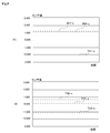
- FIG. 5 is a diagram for explaining an example of setting a threshold, in which (A) shows an example of the threshold during traveling, and (B) shows an example of the threshold during parking. is there.
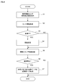
- FIG. 6 is a flowchart showing an abnormality determination process performed by the drive recorder shown in FIG.
- an abnormality detection apparatus an abnormality detection method, an abnormality detection computer program, and a recording apparatus for a vehicle according to an embodiment of the present invention will be described with reference to FIGS. While explaining.
- an event that is desired to be detected as an abnormality is, for example, a sudden start, a sudden brake, an impact by a sharp steering wheel if the vehicle is traveling, a collision by another vehicle if the vehicle is parked.
- Actions that can damage the own vehicle other cars, actions by which the car body is rubbed by a cart, etc., destruction of window glass, contact of side mirrors and doors, punctures of tires), and theft of tires are listed.
- an event that is desired to be detected as an abnormality may be an event other than the above-described event.
- FIG. 1 is a schematic view showing an appearance and an installation example of a drive recorder 1 according to an embodiment of the present invention, wherein (A) is an installation example, (B) is a front view, and (C) is a bottom view. .
- the drive recorder 1 is means for recording image data (video data, travel data, etc.) indicating the driving condition of the vehicle.
- the drive recorder 1 is mounted on the windshield 3 via a mount base 4 on the back of the rearview mirror 2 of the vehicle.
- the direction on the room mirror 2 side viewed from the drive recorder 1 is taken as the X1 direction
- the opposite direction to the X1 direction is taken as the X2 direction.
- the side of the windshield 3 is the Z1 direction as viewed from the drive recorder 1 and the rearview mirror 2, and the opposite direction to the Z1 direction is the Z2 direction.
- the drive recorder 1 includes a camera lens 5 on the front.
- the camera lens 5 captures an image in front of the vehicle (X2 direction).
- the direction from the center of the drive recorder to the camera lens 5 is taken as the Y2 direction, and the opposite direction to the Y2 direction is taken as the Y1 direction.
- the microphone unit 7 and the speaker unit 8 are provided on the back side of the drive recorder 1.
- FIG. 2 is a block diagram showing an example of the hardware configuration of the drive recorder 1 shown in FIG.
- the drive recorder 1 includes a central processing unit (CPU) 11, a main imaging unit 12, a secondary imaging unit 13, an acceleration sensor 14, an internal memory 15, a GPS (Global Positioning System) receiving unit 16, The sensor 17, the recording unit 18, the speaker 19, the microphone 20, and the input unit 21 are provided.
- CPU central processing unit
- main imaging unit 12 a main imaging unit 12
- secondary imaging unit 13 an acceleration sensor 14
- an internal memory a GPS (Global Positioning System) receiving unit 16
- the sensor 17, the recording unit 18, the speaker 19, the microphone 20, and the input unit 21 are provided.
- GPS Global Positioning System
- the CPU 11 operates in accordance with a control program and control data stored in the internal memory 15 and controls each part of the drive recorder 1 in a centralized manner.
- the CPU 11 implements the functions described later by executing the control program stored in the internal memory 15.
- the main imaging unit 12 is a camera that includes the camera lens 5 shown in FIG. 1 and is equipped with, for example, a CCD (Charge-Coupled Device) sensor or a CMOS (Complementary MOS) sensor.
- CCD Charge-Coupled Device
- CMOS Complementary MOS
- the secondary imaging unit 13 is a camera equipped with a CMOS sensor or the like capable of imaging 360 degrees around.
- the acceleration sensor 14 is, for example, a sensor that detects accelerations in the directions of three axes of x, y, and z axes, and detects a change in physical position of the drive recorder 1.
- the acceleration sensor 14 functions as a detection unit that detects the vibration of the vehicle.
- the internal memory 15 is composed of a ROM (Read Only Memory), a RAM (Random Access Memory), and the like.
- the ROM is used as a storage area for a control program (not shown) or the like executed by the CPU 11.
- the RAM is used not only as a work area for the CPU 11, but also as a buffer area for temporarily storing image data (image data 15A in FIG. 4 described later) for a predetermined time (a few seconds to a few minutes). .
- the GPS receiving unit 16 receives GPS signals transmitted from GPS satellites (not shown).
- the CPU 11 can execute positioning operation processing based on the received GPS signal, and can detect position information including the latitude, longitude, and altitude of the drive recorder 1 at the current time.
- the GPS receiving unit 16 may receive GPS signals of other devices such as car navigation (not shown).
- the illuminance sensor 17 detects illuminance information (brightness) around the vehicle.
- the recording unit 18 is, for example, an SD memory card or the like, and is a flash memory capable of recording the image data captured by the main imaging unit 12.
- the speaker 19 includes the speaker unit 8 shown in FIG. 1 and can output a voice and a voice guide for reproducing a recorded file, an operation sound, and the like.
- the microphone 20 includes the microphone unit 7 of FIG. 1 and can record surrounding sound during video recording.
- the input unit 21 is an interface that includes physical operation buttons (not shown) and is used to input various types of information to the CPU 11.
- FIG. 3 is a view showing an image of a normal recording operation when detecting an abnormality in the drive recorder 1 shown in FIG. 1 and FIG.
- the image data (image data 15A in FIG. 4 described later) captured by the main imaging unit 12 is in an area for recording an abnormality in the internal memory 15 (error recording area 48 in FIG. 4 described later) Are recorded cyclically. That is, when the image data 15A is sequentially recorded from the first logical address (or physical address) in the internal memory 15 to the last logical address (or physical address), the first logical address (or physical) is again reproduced.
- the recording start position returns to the address, and the image data is overwritten as it is. If the value detected by the acceleration sensor 14 exceeds a predetermined threshold while executing such a cyclical recording method, it is detected as abnormal by the control of the CPU 11, and before and after the detected timing The image data in the predetermined period is transferred to the recording unit 18 under the control of the CPU 11. By this transfer, the image data before and after the abnormality detection is recorded in the recording unit 18 in which the overwrite is prohibited.
- FIG. 4 is a diagram illustrating each configuration of the drive recorder 1 shown in FIG. 1 in more detail for each function of the present invention.
- the CPU 11 of the drive recorder 1 includes the functions of an information acquisition unit 41, a threshold setting unit 42, an abnormality determination unit 43, and a recording process control unit 44.
- the recording unit 18 also has an abnormal recording area 48 for recording the image data 48A.
- Drive recorder 1 may include functions other than the functions described above.
- the information acquisition unit 41 acquires vehicle peripheral information including a surrounding image captured by the secondary imaging unit 13, ambient illumination information detected by the illumination sensor 17, and ambient sound information detected by the microphone 20. Further, the information acquisition unit 41 acquires vehicle information including gear information, engine OFF information, and the like via a controller area network (CAN) or the like. The acquired vehicle peripheral information and the vehicle information are supplied to the threshold setting unit 42.
- the information acquisition unit 41 functions as a vehicle peripheral information acquisition unit that acquires vehicle peripheral information, and a vehicle information acquisition unit that acquires information related to the driving state of the vehicle.
- the threshold setting unit 42 determines whether the vehicle is parked based on the vehicle information supplied from the information acquisition unit 41, and when it is determined that the vehicle is parked, based on the vehicle periphery information supplied from the information acquisition unit 41.
- the threshold value set in advance is changed to make it easy to determine that there is an abnormality.
- the vehicle peripheral information supplied from the information acquiring unit 41 is sound information around the vehicle detected by the microphone 20, and the volume of the acquired sound is equal to or less than the predetermined value A1.
- the threshold value is changed to make it easy to determine that it is abnormal, in the case where it is a predetermined value A2 or more that is set separately.
- the threshold setting unit 42 determines the voice of a person from the acquired sound information, and changes the threshold so that it is easily determined as abnormal if the volume of the voice of the person is equal to or less than a predetermined value A3.
- the threshold setting unit 42 determines the number of people who have issued a voice from the voice of the acquired person, and changes the threshold so that it is easy to determine as abnormal if the number of people who issue a voice is equal to or less than a predetermined value A4.
- the threshold setting unit 42 functions as a voice determination unit that determines a person's voice from sound information included in vehicle peripheral information, and a number determination unit that determines the number of people who have issued a voice from the determined person's voice. Also have.
- the threshold setting unit 42 indicates that the vehicle peripheral information supplied from the information acquiring unit 41 is illuminance information of the vehicle periphery detected by the illuminance sensor 17 and the acquired illuminance information is less than or equal to the predetermined value B. Change the threshold to make it easier to judge.
- the threshold setting unit 42 is a video of the vehicle surroundings captured by the sub-imaging unit 13 with the vehicle peripheral information supplied from the information acquisition unit 41, and performs known motion detection processing on the acquired captured video, When the motion information as the processing result is equal to or more than the predetermined value C, the threshold value is changed so as to easily determine that it is abnormal.
- the abnormality determination unit 43 compares the sensor information supplied from the acceleration sensor 14 with the threshold value set by the threshold value setting unit 42, and whether an abnormality that needs to be recorded in the abnormality recording area 48 of the recording unit 18 has occurred In other words, it is determined whether the sensor output value detected by the acceleration sensor 14 exceeds a threshold, and the determination result is supplied to the recording processing control unit 44.
- the recording process control unit 44 transfers the image data 15A from the internal memory 15 to the recording unit 18 at a predetermined time before and after the timing determined as an abnormality. To record as image data 48A.
- the abnormal recording area 48 is a storage area in which overwriting of the recording unit 18 is prohibited, and the image data 15A of a predetermined period determined by the recording processing control unit 44 to be abnormal is transferred from the internal memory 15 It is recorded as image data 48A.
- FIG. 5 is a diagram illustrating an example of the threshold.
- (A) shows an example of a threshold during traveling
- (B) shows an example of a threshold during parking.
- the horizontal axis in FIG. 5 indicates time, and the vertical axis indicates sensor values.
- TH1-x and TH2-x are threshold values in the X-axis direction among sensor output values output from the acceleration sensor 14,
- TH1-y and TH2-y are Y-axis values among sensor output values output from the acceleration sensor 14
- Direction thresholds TH1-z and TH2-z indicate thresholds in the Z-axis direction among sensor output values output from the acceleration sensor 14.
- the threshold values shown in FIG. 5 different values are used during traveling and during parking.
- traveling if the sensor output value in the X-axis direction among sensor output values detected by the acceleration sensor 14 is equal to or greater than the threshold TH1-x, or if the sensor output value in the Y-axis direction is equal to or greater than the threshold TH1-y, or When the sensor output value in the Z-axis direction is equal to or greater than the threshold TH1-z, it can be determined that an abnormality has occurred.
- the sensor value in the X-axis direction among sensor output values detected by the acceleration sensor 14 is equal to or greater than the threshold TH2-x, or if the sensor output value in the Y-axis direction is equal to or greater than the threshold TH2-y, or Z If the sensor output value in the axial direction is equal to or greater than the threshold TH2-z, it can be determined that an abnormality has occurred.
- the threshold TH1 of the sensor output value of the acceleration sensor 14 is set to a high value so that an abnormality (large change) such as a collision (accident) or a sudden brake can be detected.
- a threshold value TH2 that makes it easy to determine an abnormality is set.
- the threshold TH2-y of the sensor output in the Y-axis direction and the reduction width or change width of the threshold TH2-z of the sensor output in the Z-axis direction are in the X-axis direction.
- the sensor output value threshold value TH2-x is set to be larger than the reduction width or the change width of the sensor output value.
- step S 1 the information acquisition unit 41 acquires vehicle information including gear information, engine OFF information, etc. via CAN, and an image of the surroundings of the vehicle taken by the secondary imaging unit 13, detected by the illuminance sensor 17 Vehicle peripheral information including the illuminance information around the vehicle and the sound information around the vehicle detected by the microphone 20 is acquired.
- step S2 the abnormality determination unit 43 acquires sensor information supplied from the acceleration sensor 14.
- step S3 the threshold setting unit 42 determines whether the vehicle is parked based on the vehicle information acquired in step S1. If it is determined that the vehicle is parked (YES in step S3), the process proceeds to step S4.
- the threshold value is changed based on the vehicle periphery information acquired in step S1 so as to facilitate determination as an abnormality. By this, even if there is a damage such as a car crash or a mischief, an abnormality can be detected with high accuracy.
- step S3 when it is determined in step S3 that the threshold setting unit 42 is not parked (NO in step S3), the process of step S4 is skipped, and the process proceeds to step S5.
- step S5 the abnormality determination unit 43 compares the sensor information acquired in step S2 with the threshold set by the threshold setting unit 42, and supplies the comparison result to the recording processing control unit 44.
- step S6 the recording process control unit 44 determines whether an abnormality has occurred based on the comparison result supplied from the abnormality determination unit 43, and when it is determined that an abnormality has occurred (YES in step S6), In step S7, the image data 15A at a predetermined time before and after the timing determined to be abnormal is transferred from the internal memory 15 to the recording unit 18. As a result, the image data 48A before and after the abnormality detection is recorded in the recording unit 18.
- step S6 when the recording processing control unit 44 determines that no abnormality has occurred from the comparison result supplied from the abnormality determining unit 43 in step S6 (NO in step S6), the image data is not transferred to the recording unit 18 To control.
- the drive recorder 1 sets a threshold for setting a detection unit (acceleration sensor 14) for detecting the vibration of the vehicle and a threshold value for determining whether the output value of the detection unit is abnormal.
- a vehicle peripheral information acquisition unit (information acquisition unit 41) for acquiring at least one of a unit 42, an image around the vehicle, illuminance information around the vehicle, and sound information around the vehicle;
- the vehicle information acquisition unit (information acquisition unit 41) for acquiring information related to the vehicle, and when it is determined from the vehicle information that the vehicle is parked, the threshold value is controlled based on the vehicle peripheral information. Abnormality can be detected with high accuracy according to the surrounding conditions.
- the output of the detection unit is a sensor output value in the front-rear direction, the left-right direction, and the up-down direction with respect to the vehicle
- the threshold value is a reduction width of the threshold in the left-right direction and the up-down direction with respect to the vehicle. Since it is made larger than the reduction width of the threshold value in the front and rear direction, it is possible to detect an abnormality with high accuracy even when there is a damage such as a car crash or mischief.
- the threshold value is changed to make it easy to determine that it is abnormal if the illuminance information on the vehicle periphery included in the vehicle peripheral information is equal to or less than a predetermined value, higher accuracy is obtained when the vehicle is parked and the environment is dark.
- By detecting an abnormality in the image it is possible to record an image in a situation where a car storm or a mischief is likely to occur, and to make it easy to shoot an evidence image.
- the threshold value is changed so as to make it easy to determine that it is abnormal.
- the video recording is performed in a situation where a car crash or mischief is likely to occur, and the evidence video is taken It can be made easy.
- the number of people who issued a voice is judged from the voice of the person included in the vehicle peripheral information, and when the number of people who issued a voice is equal to or less than a predetermined value, the threshold is changed to facilitate determination as abnormal. And, in the situation where there is a possibility that a suspicious person may exist around the vehicle, by detecting the abnormality with high accuracy, the video recording is performed in the situation where the on-vehicle storm or mischief is likely to occur, and the evidence video is It can be made easy to shoot.
- the drive recorder 1 also sets an imaging unit (main imaging unit 12) that outputs a captured image as image data, a sensor output value detected by a detection unit (acceleration sensor 14), and a threshold setting unit 42.
- an imaging unit main imaging unit 12
- a sensor output value detected by a detection unit acceleration sensor 14
- a threshold setting unit 42 a threshold setting unit 42.
- the imaging part which is mounted in vehicles, not shown, illumination intensity sensor It may be acquired from a microphone or the like. That is, by not providing the sub imaging unit 13, the illuminance sensor 17, and the microphone 20, the drive recorder 1 can be miniaturized, and the present invention can be realized with a simple configuration.
- the functions of the drive recorder 1 may or may not be all in the same case.
- partial functions of the abnormality detection apparatus including the acceleration sensor 14, the threshold setting unit 42, and the information acquisition unit 41 may be accommodated in a case different from the drive recorder 1.
- a part of the functions of the vehicle recording apparatus including the main imaging unit 12, the abnormality determination unit 43, and the recording processing control unit 44 are provided in a case different from the drive recorder 1. It may be stored.
- the threshold value during parking is changed, but the present invention is not limited to this, and it is determined from the position information detected by the GPS receiving unit 16 that a car wash is usually used. In the case where it is determined, the abnormality determination process may be temporarily stopped without changing the threshold during parking.
- a threshold of illuminance or volume for changing a threshold for determining abnormality may be set for each parking lot.
- the threshold value TH1-x of the sensor output value in the X-axis direction and the threshold value TH1-y of the sensor output value in the Y-axis direction are substantially equal when traveling.
- the threshold TH1-z of the sensor output value in the Z-axis direction is set to be higher.
- the decrease width of the sensor output value threshold TH2-y in the Y axis direction and the threshold TH2-z of the sensor output value in the Z axis direction is in the X axis direction. It is set to be larger than the reduction width of the threshold TH2-x of the sensor output value.
- the present invention is not limited to this, for example, the threshold TH1-x of the sensor output value in the X-axis direction, the threshold TH1-y of the sensor output value in the Y-axis direction, and the threshold TH1-z of the sensor output value in the Z-axis direction.
- the threshold value TH2 of the sensor output value of each axis at the time of parking may be set to an equal level by setting higher than that. This makes it easier to detect an abnormality such as a collision or a sudden brake, without detecting as abnormal the behavior of the vehicle body due to normal steering wheel operation or braking operation, the vibration of the vehicle body due to unevenness of the road surface, etc. Even slight changes (abnormality) can be detected.
- the series of processes described above can be performed by hardware or software.
- various functions can be implemented by installing a computer in which a computer program that configures the software is incorporated in dedicated hardware or various computer programs.
- the program is installed from a program storage medium, for example, on a general-purpose personal computer that can be executed.
- the program executed by the computer may be a program that performs processing in chronological order according to the order described in this specification, in parallel, or when necessary, such as when a call is made. It may be a program to be processed.
- SYMBOLS 1 drive recorder 11 CPU, 12 main imaging part, 13 sub imaging part, 14 acceleration sensor, 15 internal memory, 16 GPS receiving part, 17 illuminance sensor, 18 recording part, 41 information acquisition part, 42 threshold setting part, 43 abnormality Judgment unit, 44 Recording processing control unit
Landscapes
- Physics & Mathematics (AREA)
- General Physics & Mathematics (AREA)
- Engineering & Computer Science (AREA)
- Multimedia (AREA)
- Mechanical Engineering (AREA)
- Theoretical Computer Science (AREA)
- Business, Economics & Management (AREA)
- Emergency Management (AREA)
- Traffic Control Systems (AREA)
- Time Recorders, Dirve Recorders, Access Control (AREA)
Abstract
L'invention concerne un dispositif de détection d'anomalie, un procédé de détection d'anomalie, un programme d'ordinateur de détection d'anomalie et un dispositif d'enregistrement de véhicule pouvant commander une valeur de seuil pour détecter une anomalie en fonction des circonstances dans la périphérie d'un véhicule. La présente invention comprend : une unité de détection pour détecter un tremblement d'un véhicule ; une unité de réglage de valeur de seuil pour régler une valeur de seuil pour déterminer si le tremblement détecté du véhicule est anormal ; une unité d'acquisition d'informations de périphérie de véhicule pour acquérir au moins un élément parmi une image de la périphérie du véhicule, des informations d'éclairage provenant de la périphérie du véhicule, et des informations sonores provenant de la périphérie du véhicule ; et une unité d'acquisition d'informations de véhicule pour acquérir des informations relatives à l'état de conduite du véhicule. L'unité de réglage de seuil commande la valeur de seuil sur la base des informations acquises par l'unité d'acquisition d'informations de périphérie de véhicule s'il est déterminé à partir des informations acquises par l'unité d'acquisition d'informations de véhicule que le véhicule est stationné.
Priority Applications (2)
| Application Number | Priority Date | Filing Date | Title |
|---|---|---|---|
| EP18879024.0A EP3605474B1 (fr) | 2017-11-15 | 2018-10-23 | Dispositif de détection d'anomalie, procédé de détection d'anomalie, support de stockage non transitoire pour programme d'ordinateur de détection d'anomalie et dispositif d'enregistrement de véhicule |
| US16/662,097 US11273779B2 (en) | 2017-11-15 | 2019-10-24 | Abnormality detection device, method for abnormality detection, non-transitory storage medium for abnormality detection, and vehicle recording device |
Applications Claiming Priority (2)
| Application Number | Priority Date | Filing Date | Title |
|---|---|---|---|
| JP2017220165A JP6583392B2 (ja) | 2017-11-15 | 2017-11-15 | 異常検知装置、異常検知方法および異常検知プログラム、並びに車両用記録装置 |
| JP2017-220165 | 2017-11-15 |
Related Child Applications (1)
| Application Number | Title | Priority Date | Filing Date |
|---|---|---|---|
| US16/662,097 Continuation US11273779B2 (en) | 2017-11-15 | 2019-10-24 | Abnormality detection device, method for abnormality detection, non-transitory storage medium for abnormality detection, and vehicle recording device |
Publications (1)
| Publication Number | Publication Date |
|---|---|
| WO2019097962A1 true WO2019097962A1 (fr) | 2019-05-23 |
Family
ID=66540156
Family Applications (1)
| Application Number | Title | Priority Date | Filing Date |
|---|---|---|---|
| PCT/JP2018/039324 Ceased WO2019097962A1 (fr) | 2017-11-15 | 2018-10-23 | Dispositif de détection d'anomalie, procédé de détection d'anomalie, programme d'ordinateur de détection d'anomalie et dispositif d'enregistrement de véhicule |
Country Status (4)
| Country | Link |
|---|---|
| US (1) | US11273779B2 (fr) |
| EP (1) | EP3605474B1 (fr) |
| JP (1) | JP6583392B2 (fr) |
| WO (1) | WO2019097962A1 (fr) |
Cited By (3)
| Publication number | Priority date | Publication date | Assignee | Title |
|---|---|---|---|---|
| CN110349292A (zh) * | 2019-07-15 | 2019-10-18 | 西安邮电大学 | 一种基于智能手机平台的行车状态监控方法 |
| WO2020211322A1 (fr) | 2019-04-15 | 2020-10-22 | Yangtze Memory Technologies Co., Ltd. | Dispositifs à semi-conducteur unifiés ayant un dispositif logique programmable et des mémoires hétérogènes et leurs procédés de formation |
| WO2020241088A1 (fr) * | 2019-05-30 | 2020-12-03 | 株式会社Jvcケンウッド | Dispositif de commande d'enregistrement de véhicule, procédé de commande d'enregistrement, et programme |
Families Citing this family (8)
| Publication number | Priority date | Publication date | Assignee | Title |
|---|---|---|---|---|
| JP7255425B2 (ja) * | 2019-08-28 | 2023-04-11 | 株式会社Jvcケンウッド | 記録制御装置、記録制御方法、およびプログラム |
| JP7367556B2 (ja) * | 2020-02-21 | 2023-10-24 | 株式会社Jvcケンウッド | 記録制御装置、記録制御方法、およびプログラム |
| CN112061080B (zh) * | 2020-09-08 | 2022-04-19 | 中国第一汽车股份有限公司 | 车辆异动检测方法、装置、设备和介质 |
| JP7388338B2 (ja) * | 2020-10-30 | 2023-11-29 | トヨタ自動車株式会社 | 運転支援システム |
| JP2022189031A (ja) * | 2021-06-10 | 2022-12-22 | トヨタ自動車株式会社 | 自動車 |
| JP7658227B2 (ja) | 2021-09-21 | 2025-04-08 | 株式会社Jvcケンウッド | 撮像装置、撮像装置の制御方法及び撮像装置の制御プログラム |
| JP7649233B2 (ja) * | 2021-11-26 | 2025-03-19 | アルプスアルパイン株式会社 | 録画制御装置および録画制御方法 |
| JP7646591B2 (ja) | 2022-03-15 | 2025-03-17 | 株式会社東芝 | 状態監視装置、方法及びプログラム |
Citations (6)
| Publication number | Priority date | Publication date | Assignee | Title |
|---|---|---|---|---|
| JP2005161996A (ja) | 2003-12-02 | 2005-06-23 | Mitsubishi Electric Corp | 車両周辺監視システム |
| JP2006235732A (ja) * | 2005-02-22 | 2006-09-07 | Sanyo Electric Co Ltd | ドライブレコーダ |
| JP2007161226A (ja) | 2005-11-18 | 2007-06-28 | Denso Corp | 車両用盗難防止装置 |
| JP2008189140A (ja) * | 2007-02-05 | 2008-08-21 | Denso Corp | 車載用車両盗難防止装置 |
| JP2010128610A (ja) | 2008-11-25 | 2010-06-10 | Fujitsu Ten Ltd | ドライブレコーダ |
| WO2017013685A1 (fr) * | 2015-07-17 | 2017-01-26 | Gheorghiu Adrian | Appareil pour alerter automatiquement en cas de collision d'un moyen de transport |
Family Cites Families (9)
| Publication number | Priority date | Publication date | Assignee | Title |
|---|---|---|---|---|
| JP2007011965A (ja) * | 2005-07-04 | 2007-01-18 | Oki Electric Ind Co Ltd | 本人認証システム、本人認証方法及び管理システム |
| DE102006049904B4 (de) | 2005-10-24 | 2009-10-29 | DENSO CORPORATION, Kariya-shi | Neigungssensor für ein Fahrzeug, sowie Antidiebstahlsystem hiemit |
| JP2009122946A (ja) * | 2007-11-14 | 2009-06-04 | Fujitsu Ten Ltd | 情報記憶装置 |
| KR101019914B1 (ko) * | 2010-01-22 | 2011-03-08 | 팅크웨어(주) | 내비게이션 시스템 및 차량용 내비게이션의 제어방법 |
| US20160152211A1 (en) * | 2013-03-29 | 2016-06-02 | Mobile Intelligent Alerts, Llc | Information processing system, method, apparatus, computer readable medium, and computer readable program for information exchange in vehicles |
| US20160280131A1 (en) * | 2015-03-27 | 2016-09-29 | Caruma Technologies, Inc. | Connected vehicle system |
| US10759424B2 (en) * | 2016-08-16 | 2020-09-01 | Honda Motor Co., Ltd. | Vehicle data selection system for modifying automated driving functionalities and method thereof |
| DE102017119394A1 (de) * | 2017-08-28 | 2019-02-28 | HELLA GmbH & Co. KGaA | Verfahren zur Ansteuerung mindestens eines Lichtmoduls einer Leuchteinheit eines Fahrzeugs, Leuchteinheit, Computerprogrammprodukt und computerlesbares Medium |
| US20190118751A1 (en) * | 2017-10-19 | 2019-04-25 | Ford Global Technologies, Llc | Classifying non-contact events around a vehicle based on a restraint control module accelerometer |
-
2017
- 2017-11-15 JP JP2017220165A patent/JP6583392B2/ja active Active
-
2018
- 2018-10-23 WO PCT/JP2018/039324 patent/WO2019097962A1/fr not_active Ceased
- 2018-10-23 EP EP18879024.0A patent/EP3605474B1/fr active Active
-
2019
- 2019-10-24 US US16/662,097 patent/US11273779B2/en active Active
Patent Citations (6)
| Publication number | Priority date | Publication date | Assignee | Title |
|---|---|---|---|---|
| JP2005161996A (ja) | 2003-12-02 | 2005-06-23 | Mitsubishi Electric Corp | 車両周辺監視システム |
| JP2006235732A (ja) * | 2005-02-22 | 2006-09-07 | Sanyo Electric Co Ltd | ドライブレコーダ |
| JP2007161226A (ja) | 2005-11-18 | 2007-06-28 | Denso Corp | 車両用盗難防止装置 |
| JP2008189140A (ja) * | 2007-02-05 | 2008-08-21 | Denso Corp | 車載用車両盗難防止装置 |
| JP2010128610A (ja) | 2008-11-25 | 2010-06-10 | Fujitsu Ten Ltd | ドライブレコーダ |
| WO2017013685A1 (fr) * | 2015-07-17 | 2017-01-26 | Gheorghiu Adrian | Appareil pour alerter automatiquement en cas de collision d'un moyen de transport |
Non-Patent Citations (1)
| Title |
|---|
| See also references of EP3605474A4 |
Cited By (5)
| Publication number | Priority date | Publication date | Assignee | Title |
|---|---|---|---|---|
| WO2020211322A1 (fr) | 2019-04-15 | 2020-10-22 | Yangtze Memory Technologies Co., Ltd. | Dispositifs à semi-conducteur unifiés ayant un dispositif logique programmable et des mémoires hétérogènes et leurs procédés de formation |
| WO2020241088A1 (fr) * | 2019-05-30 | 2020-12-03 | 株式会社Jvcケンウッド | Dispositif de commande d'enregistrement de véhicule, procédé de commande d'enregistrement, et programme |
| JP2020194505A (ja) * | 2019-05-30 | 2020-12-03 | 株式会社Jvcケンウッド | 車両用記録制御装置、記録制御方法及びプログラム |
| JP7215333B2 (ja) | 2019-05-30 | 2023-01-31 | 株式会社Jvcケンウッド | 車両用記録制御装置、記録制御方法及びプログラム |
| CN110349292A (zh) * | 2019-07-15 | 2019-10-18 | 西安邮电大学 | 一种基于智能手机平台的行车状态监控方法 |
Also Published As
| Publication number | Publication date |
|---|---|
| JP6583392B2 (ja) | 2019-10-02 |
| JP2019091292A (ja) | 2019-06-13 |
| EP3605474B1 (fr) | 2022-07-06 |
| EP3605474A1 (fr) | 2020-02-05 |
| US20200055476A1 (en) | 2020-02-20 |
| US11273779B2 (en) | 2022-03-15 |
| EP3605474A4 (fr) | 2020-06-03 |
Similar Documents
| Publication | Publication Date | Title |
|---|---|---|
| JP6583392B2 (ja) | 異常検知装置、異常検知方法および異常検知プログラム、並びに車両用記録装置 | |
| US10497355B2 (en) | Driving information recording device, driving information playback device, controlling device, driving information recording method, and driving information recording program | |
| JP6693357B2 (ja) | 画像記録装置、画像記録方法およびプログラム | |
| JP2018005884A (ja) | 画像記録装置、画像記録方法および画像記録プログラム | |
| JP2000043764A (ja) | 車両用走行状況記録装置及び車両状況監視装置 | |
| JP2009280109A (ja) | 車両周辺監視装置 | |
| WO2020129279A1 (fr) | Dispositif, système, procédé et programme de commande d'enregistrement | |
| CN111183458B (zh) | 记录再现装置、记录再现方法以及程序 | |
| JP6828725B2 (ja) | 記録再生装置、記録再生方法、およびプログラム | |
| KR101580567B1 (ko) | 이벤트 영상 촬영 녹화 장치, 이벤트 영상 제공 방법 | |
| JP7057074B2 (ja) | 車載器および運転支援装置 | |
| US11995927B2 (en) | On-vehicle recording control apparatus, on-vehicle recording apparatus, on-vehicle recording control method, and non-transitory computer-readable recording medium | |
| CN115336248B (zh) | 车辆用记录控制装置以及记录控制方法 | |
| US11580750B2 (en) | Recording apparatus, recording method, and non-transitory computer-readable medium | |
| JPWO2020008568A1 (ja) | 報知対象検知装置、警報システムおよび報知対象検知方法 | |
| JP7447455B2 (ja) | 車両用記録制御装置および車両用記録制御方法 | |
| JP2021073571A (ja) | 記録再生装置、記録再生方法、およびプログラム | |
| JP7218787B2 (ja) | 記録再生装置 | |
| JP6939944B2 (ja) | 再生装置、再生方法、およびプログラム | |
| JP7647475B2 (ja) | 車両用記録制御装置および記録制御方法 | |
| WO2018003613A1 (fr) | Dispositif d'enregistrement d'image, procédé d'enregistrement d'image, et programme d'enregistrement d'image | |
| JP2023143337A (ja) | 車両用記録制御装置、および車両用記録制御方法 | |
| JP2025055377A (ja) | 映像記録装置 | |
| CN120922047A (zh) | 车辆安全系统和方法 | |
| JP2022056922A (ja) | 車両用記録制御装置、記録制御方法およびプログラム |
Legal Events
| Date | Code | Title | Description |
|---|---|---|---|
| 121 | Ep: the epo has been informed by wipo that ep was designated in this application |
Ref document number: 18879024 Country of ref document: EP Kind code of ref document: A1 |
|
| ENP | Entry into the national phase |
Ref document number: 2018879024 Country of ref document: EP Effective date: 20191031 |
|
| NENP | Non-entry into the national phase |
Ref country code: DE |