WO2019098031A1 - Dispositif de mélange de révélateur et dispositif de formation d'image - Google Patents
Dispositif de mélange de révélateur et dispositif de formation d'image Download PDFInfo
- Publication number
- WO2019098031A1 WO2019098031A1 PCT/JP2018/040617 JP2018040617W WO2019098031A1 WO 2019098031 A1 WO2019098031 A1 WO 2019098031A1 JP 2018040617 W JP2018040617 W JP 2018040617W WO 2019098031 A1 WO2019098031 A1 WO 2019098031A1
- Authority
- WO
- WIPO (PCT)
- Prior art keywords
- toner
- liquid
- developer
- liquid developer
- carrier
- Prior art date
- Legal status (The legal status is an assumption and is not a legal conclusion. Google has not performed a legal analysis and makes no representation as to the accuracy of the status listed.)
- Ceased
Links
Images




Classifications
-
- G—PHYSICS
- G03—PHOTOGRAPHY; CINEMATOGRAPHY; ANALOGOUS TECHNIQUES USING WAVES OTHER THAN OPTICAL WAVES; ELECTROGRAPHY; HOLOGRAPHY
- G03G—ELECTROGRAPHY; ELECTROPHOTOGRAPHY; MAGNETOGRAPHY
- G03G15/00—Apparatus for electrographic processes using a charge pattern
- G03G15/06—Apparatus for electrographic processes using a charge pattern for developing
- G03G15/10—Apparatus for electrographic processes using a charge pattern for developing using a liquid developer
Definitions
- a developer mixing apparatus for stirring and mixing toner and carrier liquid to form a liquid developer, and an electrophotographic image for forming an image using the liquid developer generated by the developer mixing apparatus It relates to a forming apparatus.
- an image forming apparatus that forms an image using a liquid developer containing toner and a carrier liquid.
- the liquid developer is contained in a mixer and supplied from the mixer to the developing device to be used for development.
- the toner for replenishment is stored in the toner tank
- the carrier liquid for replenishment is stored in the carrier tank
- the toner and the carrier liquid are replenished to the mixer from each tank.
- the mixer is provided with a stirring member to mix and disperse the toner in the carrier liquid to generate a liquid developer (Patent Document 1).
- the mixer is provided with a toner concentration sensor that detects the toner concentration of the liquid developer (the ratio of the toner weight (T) to the total weight of the toner and carrier liquid (D)), and based on the detection result, The adjusted liquid developer is supplied to the developing device.
- a toner concentration sensor that detects the toner concentration of the liquid developer (the ratio of the toner weight (T) to the total weight of the toner and carrier liquid (D)), and based on the detection result, The adjusted liquid developer is supplied to the developing device.
- image defects may occur due to the toner concentration of the liquid developer supplied from the mixer to the developing device not being an appropriate concentration.
- the present invention has been made in view of the above problems, and an object of the present invention is to provide a developer mixing device capable of supplying a liquid developer having an appropriate toner concentration from a mixer having a toner concentration sensor to a developing device.
- the developer mixing device is capable of containing a liquid developer composed of toner and carrier liquid, wherein the inflow portion capable of flowing the toner and the carrier liquid, and a discharge portion capable of discharging the liquid developer.
- a container body having a flow path portion through which liquid developer flows from the inflow portion toward the discharge portion; a stirring portion disposed in the flow path portion for stirring the liquid developer in the container body;
- the toner concentration of the liquid developer in the container main body can be detected downstream of the stirring unit and upstream of the discharge unit with respect to the flow path direction from the inflow unit to the discharge unit along the passage unit. And a detection unit.
- the toner concentration of the liquid developer is detected by the detection unit while the toner and the carrier liquid are stirred to stabilize the toner concentration, and the liquid developer in the state where the toner concentration is stable is discharged. It can be realized with a simple configuration to discharge from the department.
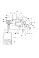
- FIG. 1 is a schematic configuration view showing an image forming apparatus suitable using the developer mixing device of the present embodiment.
- FIG. 2 is a schematic view showing a transport path of a liquid developer.
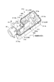
- FIG. 1 is an external perspective view showing a developer mixing device of a first embodiment.
- FIG. 2 is a perspective view showing a part of the developer mixing device of the first embodiment.
- the external appearance perspective view which shows the developer mixing apparatus of 2nd embodiment.
- the perspective view which cuts and shows a part of developer mixing device of a second embodiment.
- FIG. 7 is a schematic view showing a transport path of a liquid developer according to another embodiment.
- An image forming apparatus 100 illustrated in FIG. 1 is an electrophotographic digital printer that forms a toner image on a recording material S (a sheet, a sheet material such as an OHP sheet, etc.).
- the image forming apparatus 100 operates based on an image signal, transfers the toner image formed by the image forming unit 12 to the recording material S sequentially conveyed from the cassettes 11a and 11b, and then obtains an image by fixing.
- the image signal is sent to the image forming apparatus 100 from an external terminal such as a scanner or a personal computer (not shown).
- the operation of the image forming apparatus 100 is controlled by a control unit (not shown).
- the image forming unit 12 includes a photosensitive drum 13 as a photosensitive member, a charger 14, a laser exposure device 15, a developing device 16, and a drum cleaner 19.
- the laser light E is irradiated from the laser exposure device 15 according to the image signal onto the photosensitive drum 13 whose surface is charged by the charger 14, and an electrostatic latent image is formed on the photosensitive drum 13.
- the electrostatic latent image is developed by the developing device 16 as a toner image.
- the developing device 16 as a developing device contains a liquid developer D in which powder toner as a dispersoid is dispersed in a carrier liquid as a dispersion medium. The developing unit 16 performs development using this liquid developer D.
- the liquid developer D is generated by mixing and dispersing the carrier liquid C and the toner T at a predetermined ratio (for example, 5 ⁇ 0.5%) in the mixer 31 as a developer mixing device (mixer). Is supplied to the developing unit 16.
- the carrier liquid C for replenishment is accommodated in a carrier tank 32 as a carrier container, and the toner T for replenishment is accommodated in a toner tank 33 as a toner container. Then, according to the mixed state of the carrier liquid C and the toner T in the mixer 31, the carrier liquid C or the toner T is supplied to the mixer 31 from each tank.
- a stirring member is disposed in the mixer 31, and the mixer 31 disperses the toner in the carrier liquid by stirring and mixing the supplied carrier liquid and the toner T by the stirring member.
- the configuration of the mixer 31 will be described later (see FIGS. 3 and 4).
- the liquid developer D supplied from the mixer 31 to the developing device 16 is coated (supplied) on the developing roller 18 by the coating roller 17 in the supply section 16 a of the developing device 16 and used for development.
- the developing roller 18 carries and conveys a liquid developer on the surface, and develops the electrostatic latent image formed on the photosensitive drum 13 with toner.
- the liquid developers (carrier liquid C and toner T) remaining on the developing roller 18 after development are collected in the collection section 16 b of the developing device 16.
- the coating of the liquid developer D from the coating roller 17 to the developing roller 18 and the development from the developing roller 18 to the electrostatic latent image on the photosensitive drum 13 are performed using an electric field.
- the toner image formed on the photosensitive drum 13 is primarily transferred to the intermediate transfer roller 20 using an electric field, and conveyed to the nip portion (secondary transfer portion) formed by the intermediate transfer roller 20 and the transfer roller 21. .
- the liquid developer remaining on the photosensitive drum 13 after the primary transfer to the intermediate transfer roller 20 is collected by the drum cleaner 19. At least one of the intermediate transfer roller 20 and the transfer roller 21 may be an endless belt.
- the recording material S accommodated in the cassettes 11a and 11b is conveyed toward the resist conveyance unit 23 by the feeding units 22a and 22b configured by conveyance rollers and the like.
- the resist conveyance unit 23 conveys the recording material S to the nip portion between the intermediate transfer roller 20 and the transfer roller 21 in accordance with the timing of the toner image transferred to the intermediate transfer roller 20.
- the toner image is secondarily transferred onto the passing recording material S.
- the recording material S to which the toner image has been transferred is conveyed to the fixing device 25 by the conveyance belt 24, and the toner image transferred to the recording material S is fixed.
- the recording material S on which the toner image is fixed is discharged to the outside of the machine, and the image process is completed.
- the fixing device 25 employs a heat fixing method. In this system, the fixing device 25 has two rollers for sandwiching the recording material S from above and below and pressing them against each other, and the two rollers maintain their surface temperature at about 200.degree.
- the surface of the recording material S conveyed at a predetermined process speed (for example, 600 mm / s) is maintained at a temperature of 60 ° C. or higher, which is the glass transition point at which the toner melts.
- the toner melts, the toner is fixed on the recording material S.
- the fixing device 25 irradiates ultraviolet light (UV light) to cure the liquid developer.
- UV light ultraviolet light
- An intermediate transfer roller cleaner 26 and a transfer roller cleaner 27 are provided on the intermediate transfer roller 20 as an intermediate transfer member and the transfer roller 21 as a transfer member, respectively.
- the intermediate transfer roller cleaner 26 recovers the liquid developer remaining on the intermediate transfer roller 20 after the secondary transfer from the intermediate transfer roller 20.
- the transfer roller cleaner 27 recovers the liquid developer remaining on the transfer roller 21 after the secondary transfer from the transfer roller 21.
- liquid developer D used in the image forming apparatus 100 of the present embodiment a liquid developer conventionally used may be used, or an ultraviolet-curable liquid developer may be used.
- a liquid developer conventionally used may be used, or an ultraviolet-curable liquid developer may be used.
- an expensive high-performance carrier liquid as the carrier liquid, if the carrier liquid recovered from the photosensitive drum 13 is discarded, the running cost becomes high. Therefore, in order to reduce the running cost, the carrier liquid can be efficiently separated and extracted from the recovered liquid developer D so that it can be reused.
- the toner particles include a coloring material that emits a color in a toner resin.
- the toner particles may contain other materials such as a charge control agent, as well as the toner resin and the coloring material.
- a charge control agent epoxy resin, styrene acrylic resin, or the like is used.
- the colorant may be a general organic-inorganic pigment.
- the curable liquid which is a carrier liquid, is composed of a charge control agent that causes a charge on the toner surface, a photopolymerization agent that generates an acid upon irradiation with ultraviolet light (UV light), and a monomer that bonds with the acid. .
- the monomer is a vinyl ether compound that polymerizes by a cationic polymerization reaction.
- a sensitizer may be contained.
- the photopolymerization agent may reduce the storage stability, so 10 to 5000 ppm of a cationic polymerization inhibitor may be added.
- charge control aids, other additives, etc. may be used.
- a carrier supply pump 41 and a toner supply pump 42 are provided on transport pipes from the carrier tank 32 and the toner tank 33 to the mixer 31, respectively.
- the carrier supply pump 41 and the toner supply pump 42 respectively adjust the replenishment amounts of the carrier liquid C and the toner T to the mixer 31.
- the mixer 31 adjusts the concentration of the liquid developer so as to adjust the toner concentration of the liquid developer detected by the toner concentration sensor 310 to a predetermined ratio (for example, 5 ⁇ 0.5%).
- a predetermined ratio for example, 5 ⁇ 0.5%).
- the carrier liquid C is supplied from the carrier tank 32 to the mixer 31.
- the toner concentration is lower than the predetermined ratio
- the toner T is supplied from the toner tank 33 to the mixer 31.
- the toner concentration of the liquid developer in the mixer 31 is adjusted to a predetermined ratio.
- the liquid developer D necessary for development is supplied to the developing unit 16 by the developer supply pump 44.
- the developing device 16 is provided with an agent amount detecting device 160, and the agent amount detecting device 160 detects the amount of liquid developer D in the developing device 16.
- the supply of the liquid developer D to the developing device 16 is performed so that the detection value of the agent amount detection device 160 becomes equal to or more than a predetermined value (for example, 200 ml).
- the liquid developer D remaining on the developing roller 18 after development and collected into the collection section 16 b of the developing device 16 is returned to the mixer 31 by the circulation pump 43 and reused.
- the liquid developer D recovered to the recovery section 16 b of the developing device 16 may be transported to the separation and extraction device 34.
- the liquid developer (toner T and carrier liquid C) collected by the drum cleaner 19, the intermediate transfer roller cleaner 26, and the transfer roller cleaner 27 is transferred to the separation and extraction device 34 by the pumps 48, 49 and 50, respectively. It is transported.
- the separation and extraction device 34 separates the toner T and the carrier liquid C by an electric field separation system to make the carrier liquid reusable. That is, the separation and extraction device 34 separates the liquid developer into the recyclable carrier liquid and the waste liquid W containing impurities such as toner and paper dust.
- the carrier liquid separated by the separation and extraction device 34 is transported to the carrier tank 32 by the separation and recovery pump 45.
- the separated waste liquid W is transported to the waste liquid recovery container 35 by the pump 47 provided in the transport pipe.
- the mixer 31 has a container main body 311 capable of containing a liquid developer composed of toner and carrier liquid.
- the container body 311 is formed in a rectangular shape.
- an inflow portion 312 is formed at one end side in the longitudinal direction, in which the toner and the carrier liquid are opened so as to be inflowable, and a discharge portion is opened at the other end side in the longitudinal direction. 318 are formed.
- the inflow portion 312 has an inflow port 312C, an inflow port 312D2, and an inflow port 312D3.
- the carrier liquid replenished from the carrier tank 32 can flow into the container body 311 from the inlet 312C.
- the toner replenished from the toner tank 33 can flow into the container body 311 from the inlet 312D2. From the inlet 312D3, the liquid developer which remains on the developing roller 18 after development and is collected into the collection section 16b of the developing device 16 can flow into the container body 311.
- the developer supply pump 44 is connected to the discharge unit 318.
- the developer supply pump 44 is, for example, a spiral pump, and operates in response to an input of a drive voltage (for example, 12 V) from an external drive source (not shown). According to the operation of the developer supply pump 44, the liquid developer in the container body 311 is discharged to the outside of the container body 311 via the discharge unit 318, and is supplied to the developing device 16.
- a stirring member 313 as a stirring portion, a toner concentration sensor 310 as a detection portion, a liquid amount detection sensor 315 as a liquid amount detection portion, a liquid temperature detection sensor as a temperature detection portion 316 and the like are arranged.
- the stirring member 313 is, for example, a stainless steel rotary shaft 313a having an outer diameter of 10 mm, and a stainless steel stirring blade 313b (protruding portion, may be a rib) having an outer diameter of 20 mm. It is a member attached so as to protrude from 313a.
- the stirring member 313 is attached with a drive input gear 313d for transmitting the rotation of the drive motor 313c to the rotation shaft 313a.
- the stirring member 313 can stir the liquid developer in the container main body 311 by being rotated by the drive motor 313 c via the drive input gear 313 d.
- the toner concentration sensor 310 is, for example, a light transmission type solid content detection device, and can detect the toner concentration of the liquid developer.
- the liquid amount detection sensor 315 is, for example, a float sensor, and can detect the liquid height of the liquid developer in the container main body 311. As one example, when the liquid developer has a predetermined height or less (e.g., 20 cm or less), replenishment of toner and carrier liquid is started. Then, when the liquid height of the liquid developer exceeds a predetermined level (for example, 40 cm or more), the replenishment of the toner and the carrier liquid is stopped.
- the liquid temperature detection sensor 316 is, for example, a metal thermometer, and can detect the liquid temperature of the liquid developer in the container main body 311.
- a predetermined level for example, 20 ° C. or lower
- heating of the liquid developer by a heater is started.
- a predetermined level for example, 50 ° C. or higher
- the heating of the liquid developer by a heater is stopped.
- a flow path portion 90 through which the liquid developer flows from the inflow portion 312 to the discharge portion 318 is formed in the container body 311 (see the arrow in FIG. 4).
- the length in the hand direction is formed to be short.
- the length in the width direction of the position where the stirring member 313 is disposed in the container main body 311 is 105% or more and 180% or less of the circumscribed circle of the stirring blade 313b (projecting portion) of the stirring member 313 It is preferably formed at 105% to 120%.
- the flow path portion 90 is formed in a shape that causes a gap with the stirring member 313 at the position where the stirring member 313 is disposed. By doing this, the liquid developer passing through the flow path 90 is sufficiently stirred by the stirring member 313 when passing through the stirring member 313. As such, the container body 311 is formed, and the stirring member 313 is disposed at the corresponding position in the container body 311.
- the toner concentration sensor 310 is located downstream of the stirring member 313 of the flow path portion 90 in the flow path direction (here, the longitudinal direction) from the inflow portion 312 to the discharge portion 318 along the flow path portion 90 It is disposed upstream of the discharge unit 318. Further, the liquid amount detection sensor 315 and the liquid temperature detection sensor 316 are also disposed downstream of the stirring member 313 of the flow passage 90 in the flow direction and upstream of the discharge portion 318 in the flow direction.
- the stirring member 313 and the toner are sequentially arranged from the upstream side to the downstream side in the flow path direction from the inflow portion 312 to the discharge portion 318 along the flow path portion 90 in the container body 311.
- a concentration sensor 310 is arranged. Then, when the liquid developer passing through the flow path portion 90 passes through the stirring member 313, the liquid developer is reliably stirred by the stirring member 313, and it is difficult for the liquid developer to reach the discharge portion 318 without being stirred. . That is, the liquid developer reaching the toner concentration sensor 310 becomes a liquid developer in a state where the toner concentration is relatively stable after the toner and the carrier liquid are sufficiently stirred by the stirring member 313.
- the liquid developer is discharged from the discharge unit 318 and supplied to the developing device 16 while the toner concentration is maintained.
- the mixer 31 of the present embodiment it is possible to stably supply the developing device 16 with the liquid developer whose toner concentration has been adjusted to a predetermined ratio in the mixer 31 based on the detection result of the toner concentration sensor 310. It can be realized with a simple configuration.
- the inflow portion 312 and the discharge portion 318 are formed at both end portions in the longitudinal direction of the container main body 311 formed in a rectangular shape, and in the container main body 311 The stirring member 313 and the toner concentration sensor 310 are disposed in this order.
- the mixer 31 and thus the image forming apparatus 100 are large in order to secure a space for housing the mixer 31 in the apparatus main body of the image forming apparatus 100. It can not but be Therefore, in the second embodiment, a mixer suitable for miniaturization is proposed.
- the basic configuration and operation in the second embodiment are the same as those in the above-described first embodiment, the description and illustration of similar configurations will be omitted or simplified, and parts different from the first embodiment will be described below. I will explain to the center.
- the mixer 31A of the second embodiment has a container main body 311A capable of containing a liquid developer composed of toner and carrier liquid.
- the inflow portion 312 and the discharge portion 318 are formed on the same one end side of the container main body 311A.
- the container main body 311A is formed in a step shape in which a part of one end portion protrudes, the inflow portion 312 is formed in the protruding protruding end portion 311Aa, and the discharging portion 318 is formed in the non protruding end portion 311Ab.
- Ru The developer supply pump 44 connected to the discharge unit 318 is disposed in the space 311Ac secured by the projecting end 311Aa and the non-projecting end 311Ab.
- the container body 311A is formed in a shape having one end having a protruding end portion 311Aa and a non-projecting end portion 311Ab.
- the container body 311A is divided into a first chamber 311a, a second chamber 311c, and a third chamber 311b by a partition member 320 which extends in the vertical direction from the bottom to the top at a substantially central portion. ing.
- the first chamber 311a and the second chamber 311c are in communication via the third chamber 311b.
- the partition member 320 partitions the inside of the container main body 311A so as to form a flow path portion 90 of the liquid developer which is folded back from the first chamber 311a to the second chamber 311c through the third chamber 311b.
- the inside of the container main body 311A is partitioned in a substantially U-shape by the partition member 320 so that the flow directions of the liquid developer in the first chamber 311a and the second chamber 311c are opposite to each other. There is.
- the toner concentration sensor 310 is disposed in the second chamber 311 c, and the stirring member 313 is disposed in the third chamber 311 b. That is, in the container main body 311, the stirring member 313 and the toner concentration sensor 310 are disposed in order from the upstream side to the downstream side in the flow path direction from the inflow portion 312 to the discharge portion 318 along the flow path portion 90. .
- the liquid amount detection sensor 315 and the liquid temperature detection sensor 316 may be disposed in the same second chamber 311 c as the toner concentration sensor 310.
- the stirring member 313 is disposed with a gap from the inner wall 311Ad of the third chamber 311b, and the partition member 320 is formed to create a gap with the stirring member 313. That is, in the third chamber 311b, the partition member 320 is formed such that the length in the width direction in which the flow passage portion 90 intersects the flow passage direction is shorter than the length in the flow passage direction.
- the distance between the tip end surface 320a of the partition member 320 and the inner wall 311Ad of the container main body 311A facing the tip end surface 320a (that is, the width of the flow passage portion 90 in the third chamber 311b) It is formed in 105% or more and 180% or less of the circle. Preferably, it is formed in 105% or more and 120% or less.
- the stirring member 313 is rotated by the drive motor 313 c so that the rotation direction is the same as the flow direction on the side close to the inner wall of the container main body 311 A (counterclockwise in FIG. 6). In this case, the liquid developer easily flows along the inner wall of the container body 311A. In this case, the flow of the liquid developer is less likely to be impaired by the stirring by the stirring member 313.
- the stirring member 313 and the toner are sequentially arranged from the upstream side to the downstream side in the flow path direction from the inflow portion 312 to the discharge portion 318 along the flow path portion 90 in the container main body 311A.
- a concentration sensor 310 is arranged. Therefore, after the toner concentration is detected by the toner concentration sensor 310, the liquid developer is discharged from the discharge unit 318 and supplied to the developing device 16 while the toner concentration is maintained. Therefore, as described above, it is possible to stably supply the liquid developer whose toner concentration is adjusted to a predetermined ratio in the mixer 31 to the developing device 16 based on the detection result of the toner concentration sensor 310 with a simple configuration. The same effect as the first embodiment is obtained.
- the flow path section 90 is formed by partitioning the inside of the container body 311A by the partition member 320.
- the container main body 311A can be easily made compact, which contributes to downsizing of the mixer 31 itself and thus the image forming apparatus 100.
- the gap between the partitioning member 320 and the stirring member 313 is easily adjusted.
- the inside of the container main body 311A is not limited to being divided into a substantially U-shape by the partition member 320, and it may be partitioned in any way as long as the flow path portion 90 from the inflow portion 312 to the discharge portion 318 is formed. .
- the interior of the container body 311A may be partitioned by a plurality of partition members 320.
- the carrier liquid C is supplied from the carrier tank 32 and the toner T is supplied from the toner tank 33 to the mixer 31 (31A). It is not limited.
- the carrier liquid is not supplied from the carrier tank 32, and the toner is not supplied directly to the mixer 31 from the toner tank 33, but these are mixed to generate a liquid developer (supplement agent) for replenishment. May be supplied to the replenishing agent producing tank 39.
- the replenishment agent generation tank 39 as a generator mixes the carrier liquid supplied from the carrier tank 32 with the toner supplied from the toner tank 33 to make the toner concentration higher than that of the liquid developer in the mixer 31 (for example, 50 ⁇ Produce 1%) of supplements.
- the generated replenishment agent can be supplied to the mixer 31 from the replenishment agent production tank 39.
- the inflow portion 312 described above (see, for example, FIG. 3 and FIG. 5) is recovered to the inlet through which the replenishing agent supplied from the replenishing agent generation tank 39 flows and the recovery section 16 b of the developing device 16 It is sufficient to have an inlet through which the liquid developer flows.
- the liquid developer or the like may be transported using its own weight without being provided with a pump, for example, if it can be transported by its own weight drop. Further, the image forming apparatus 100 may not be provided with the separation and extraction device 34 if it is unnecessary to separate and extract the toner and the carrier liquid. In that case, the liquid developer collected by the drum cleaner 19, the intermediate transfer roller cleaner 26, and the transfer roller cleaner 27 may be collected in the waste liquid collection container 35.
- the present developer mixing apparatus can be used in image forming apparatuses such as copying machines, printers, facsimiles, and multi-function machines having these functions, and is particularly suitable for use with liquid developers.
Landscapes
- Physics & Mathematics (AREA)
- General Physics & Mathematics (AREA)
- Wet Developing In Electrophotography (AREA)
Abstract
La présente invention comprend : un corps principal de récipient (311) apte à stocker un révélateur liquide constitué par un toner et un liquide porteur et ayant une section d'entrée (312) qui peut recevoir un écoulement d'entrée du toner et du liquide porteur, une section de décharge (318) qui peut décharger le révélateur liquide, et une section de passage d'écoulement (90) dans laquelle le révélateur liquide s'écoule à partir de la section d'entrée (312) vers la section de décharge (318) ; une unité d'agitateur (313) qui est disposée dans la section de passage d'écoulement (90), et configurée de façon à agiter le révélateur liquide à l'intérieur du corps principal de récipient (311) ; et une unité de détection (310) qui est disposée en aval de l'unité d'agitateur (313) et en amont de la section de décharge (318) par rapport à une direction d'écoulement dans laquelle le révélateur liquide s'écoule à partir de la section d'entrée (312) vers la section de décharge (318) le long de la section de passage d'écoulement (90), et qui est apte à détecter une concentration de toner du révélateur liquide à l'intérieur du corps principal de récipient (311).
Applications Claiming Priority (2)
| Application Number | Priority Date | Filing Date | Title |
|---|---|---|---|
| JP2017-222235 | 2017-11-17 | ||
| JP2017222235A JP7046570B2 (ja) | 2017-11-17 | 2017-11-17 | 現像剤混合装置及び画像形成装置 |
Publications (1)
| Publication Number | Publication Date |
|---|---|
| WO2019098031A1 true WO2019098031A1 (fr) | 2019-05-23 |
Family
ID=66540205
Family Applications (1)
| Application Number | Title | Priority Date | Filing Date |
|---|---|---|---|
| PCT/JP2018/040617 Ceased WO2019098031A1 (fr) | 2017-11-17 | 2018-10-31 | Dispositif de mélange de révélateur et dispositif de formation d'image |
Country Status (2)
| Country | Link |
|---|---|
| JP (1) | JP7046570B2 (fr) |
| WO (1) | WO2019098031A1 (fr) |
Citations (3)
| Publication number | Priority date | Publication date | Assignee | Title |
|---|---|---|---|---|
| JPS6217825Y2 (fr) * | 1982-09-28 | 1987-05-08 | ||
| WO2009036504A1 (fr) * | 2007-09-20 | 2009-03-26 | Research Laboratories Of Australia Pty Ltd | Systèmes de détermination de la concentration d'encre et de réapprovisionnement en encre |
| JP2011180435A (ja) * | 2010-03-02 | 2011-09-15 | Seiko Epson Corp | 濃度測定装置及び画像形成装置 |
-
2017
- 2017-11-17 JP JP2017222235A patent/JP7046570B2/ja active Active
-
2018
- 2018-10-31 WO PCT/JP2018/040617 patent/WO2019098031A1/fr not_active Ceased
Patent Citations (3)
| Publication number | Priority date | Publication date | Assignee | Title |
|---|---|---|---|---|
| JPS6217825Y2 (fr) * | 1982-09-28 | 1987-05-08 | ||
| WO2009036504A1 (fr) * | 2007-09-20 | 2009-03-26 | Research Laboratories Of Australia Pty Ltd | Systèmes de détermination de la concentration d'encre et de réapprovisionnement en encre |
| JP2011180435A (ja) * | 2010-03-02 | 2011-09-15 | Seiko Epson Corp | 濃度測定装置及び画像形成装置 |
Also Published As
| Publication number | Publication date |
|---|---|
| JP2019095488A (ja) | 2019-06-20 |
| JP7046570B2 (ja) | 2022-04-04 |
Similar Documents
| Publication | Publication Date | Title |
|---|---|---|
| US8781371B2 (en) | Stir-transport member, development device provided therewith, and image forming apparatus | |
| CN103513546B (zh) | 显影装置以及具有该显影装置的图像形成装置 | |
| US8515316B2 (en) | Developing device and image forming apparatus | |
| JP2008299196A (ja) | 現像装置および画像形成装置 | |
| US7532844B2 (en) | Process cartridge, image forming apparatus and method of assembling process cartridges | |
| JP5374939B2 (ja) | 現像装置及び画像形成装置 | |
| US9841703B2 (en) | Developing apparatus | |
| US7024151B2 (en) | Image forming apparatus and toner stirring method | |
| JP4770951B2 (ja) | 現像装置及び画像形成装置 | |
| US10007212B2 (en) | Developing apparatus having developer guiding portions | |
| JP5223370B2 (ja) | 現像剤撹拌装置及び画像形成装置 | |
| JP6108165B2 (ja) | 現像装置、プロセスユニット、及び画像形成装置 | |
| JP6537355B2 (ja) | 画像形成装置 | |
| JP7046570B2 (ja) | 現像剤混合装置及び画像形成装置 | |
| JP2021096400A (ja) | 現像装置 | |
| JP2008033171A (ja) | トナー収納容器、現像装置及びこれらを備えた画像形成装置 | |
| CN111694245B (zh) | 显影装置、图像形成单元以及图像形成装置 | |
| JP7799452B2 (ja) | 現像装置 | |
| JP5946485B2 (ja) | 現像装置およびそれを用いた画像形成装置 | |
| JP2011141368A (ja) | 現像装置、プロセスカートリッジ及び画像形成装置 | |
| JPH063961A (ja) | 現像装置 | |
| JP2009115937A (ja) | 現像剤撹拌装置、現像装置、及び、画像形成装置 | |
| JP2010217328A (ja) | 現像装置、画像形成装置、及びプロセスカートリッジ | |
| JPH063951A (ja) | 現像装置 | |
| JP2019101349A (ja) | 現像装置およびそれを備えた画像形成装置 |
Legal Events
| Date | Code | Title | Description |
|---|---|---|---|
| 121 | Ep: the epo has been informed by wipo that ep was designated in this application |
Ref document number: 18878024 Country of ref document: EP Kind code of ref document: A1 |
|
| NENP | Non-entry into the national phase |
Ref country code: DE |
|
| 122 | Ep: pct application non-entry in european phase |
Ref document number: 18878024 Country of ref document: EP Kind code of ref document: A1 |