WO2019098184A1 - 複合配線、信号取得部材、及びそれらの製造方法 - Google Patents
複合配線、信号取得部材、及びそれらの製造方法 Download PDFInfo
- Publication number
- WO2019098184A1 WO2019098184A1 PCT/JP2018/041954 JP2018041954W WO2019098184A1 WO 2019098184 A1 WO2019098184 A1 WO 2019098184A1 JP 2018041954 W JP2018041954 W JP 2018041954W WO 2019098184 A1 WO2019098184 A1 WO 2019098184A1
- Authority
- WO
- WIPO (PCT)
- Prior art keywords
- wire
- wiring
- tube
- lead
- stretchable
- Prior art date
- Legal status (The legal status is an assumption and is not a legal conclusion. Google has not performed a legal analysis and makes no representation as to the accuracy of the status listed.)
- Ceased
Links
Images




Classifications
-
- A—HUMAN NECESSITIES
- A61—MEDICAL OR VETERINARY SCIENCE; HYGIENE
- A61B—DIAGNOSIS; SURGERY; IDENTIFICATION
- A61B5/00—Measuring for diagnostic purposes; Identification of persons
- A61B5/24—Detecting, measuring or recording bioelectric or biomagnetic signals of the body or parts thereof
- A61B5/25—Bioelectric electrodes therefor
- A61B5/251—Means for maintaining electrode contact with the body
- A61B5/256—Wearable electrodes, e.g. having straps or bands
-
- A—HUMAN NECESSITIES
- A61—MEDICAL OR VETERINARY SCIENCE; HYGIENE
- A61B—DIAGNOSIS; SURGERY; IDENTIFICATION
- A61B5/00—Measuring for diagnostic purposes; Identification of persons
- A61B5/0002—Remote monitoring of patients using telemetry, e.g. transmission of vital signals via a communication network
- A61B5/0004—Remote monitoring of patients using telemetry, e.g. transmission of vital signals via a communication network characterised by the type of physiological signal transmitted
- A61B5/0006—ECG or EEG signals
-
- A—HUMAN NECESSITIES
- A61—MEDICAL OR VETERINARY SCIENCE; HYGIENE
- A61B—DIAGNOSIS; SURGERY; IDENTIFICATION
- A61B5/00—Measuring for diagnostic purposes; Identification of persons
- A61B5/24—Detecting, measuring or recording bioelectric or biomagnetic signals of the body or parts thereof
- A61B5/25—Bioelectric electrodes therefor
- A61B5/263—Bioelectric electrodes therefor characterised by the electrode materials
- A61B5/268—Bioelectric electrodes therefor characterised by the electrode materials containing conductive polymers, e.g. PEDOT:PSS polymers
-
- A—HUMAN NECESSITIES
- A61—MEDICAL OR VETERINARY SCIENCE; HYGIENE
- A61B—DIAGNOSIS; SURGERY; IDENTIFICATION
- A61B5/00—Measuring for diagnostic purposes; Identification of persons
- A61B5/24—Detecting, measuring or recording bioelectric or biomagnetic signals of the body or parts thereof
- A61B5/25—Bioelectric electrodes therefor
- A61B5/271—Arrangements of electrodes with cords, cables or leads, e.g. single leads or patient cord assemblies
- A61B5/273—Connection of cords, cables or leads to electrodes
-
- A—HUMAN NECESSITIES
- A61—MEDICAL OR VETERINARY SCIENCE; HYGIENE
- A61B—DIAGNOSIS; SURGERY; IDENTIFICATION
- A61B5/00—Measuring for diagnostic purposes; Identification of persons
- A61B5/24—Detecting, measuring or recording bioelectric or biomagnetic signals of the body or parts thereof
- A61B5/25—Bioelectric electrodes therefor
- A61B5/279—Bioelectric electrodes therefor specially adapted for particular uses
-
- A—HUMAN NECESSITIES
- A61—MEDICAL OR VETERINARY SCIENCE; HYGIENE
- A61B—DIAGNOSIS; SURGERY; IDENTIFICATION
- A61B5/00—Measuring for diagnostic purposes; Identification of persons
- A61B5/68—Arrangements of detecting, measuring or recording means, e.g. sensors, in relation to patient
- A61B5/6801—Arrangements of detecting, measuring or recording means, e.g. sensors, in relation to patient specially adapted to be attached to or worn on the body surface
- A61B5/6802—Sensor mounted on worn items
-
- A—HUMAN NECESSITIES
- A61—MEDICAL OR VETERINARY SCIENCE; HYGIENE
- A61B—DIAGNOSIS; SURGERY; IDENTIFICATION
- A61B5/00—Measuring for diagnostic purposes; Identification of persons
- A61B5/68—Arrangements of detecting, measuring or recording means, e.g. sensors, in relation to patient
- A61B5/6801—Arrangements of detecting, measuring or recording means, e.g. sensors, in relation to patient specially adapted to be attached to or worn on the body surface
- A61B5/6802—Sensor mounted on worn items
- A61B5/6804—Garments; Clothes
-
- H—ELECTRICITY
- H01—ELECTRIC ELEMENTS
- H01B—CABLES; CONDUCTORS; INSULATORS; SELECTION OF MATERIALS FOR THEIR CONDUCTIVE, INSULATING OR DIELECTRIC PROPERTIES
- H01B7/00—Insulated conductors or cables characterised by their form
-
- H—ELECTRICITY
- H01—ELECTRIC ELEMENTS
- H01B—CABLES; CONDUCTORS; INSULATORS; SELECTION OF MATERIALS FOR THEIR CONDUCTIVE, INSULATING OR DIELECTRIC PROPERTIES
- H01B7/00—Insulated conductors or cables characterised by their form
- H01B7/04—Flexible cables, conductors, or cords, e.g. trailing cables
-
- H—ELECTRICITY
- H01—ELECTRIC ELEMENTS
- H01B—CABLES; CONDUCTORS; INSULATORS; SELECTION OF MATERIALS FOR THEIR CONDUCTIVE, INSULATING OR DIELECTRIC PROPERTIES
- H01B7/00—Insulated conductors or cables characterised by their form
- H01B7/06—Extensible conductors or cables, e.g. self-coiling cords
-
- H—ELECTRICITY
- H01—ELECTRIC ELEMENTS
- H01B—CABLES; CONDUCTORS; INSULATORS; SELECTION OF MATERIALS FOR THEIR CONDUCTIVE, INSULATING OR DIELECTRIC PROPERTIES
- H01B7/00—Insulated conductors or cables characterised by their form
- H01B7/17—Protection against damage caused by external factors, e.g. sheaths or armouring
- H01B7/28—Protection against damage caused by moisture, corrosion, chemical attack or weather
- H01B7/282—Preventing penetration of fluid, e.g. water or humidity, into conductor or cable
-
- H—ELECTRICITY
- H01—ELECTRIC ELEMENTS
- H01R—ELECTRICALLY-CONDUCTIVE CONNECTIONS; STRUCTURAL ASSOCIATIONS OF A PLURALITY OF MUTUALLY-INSULATED ELECTRICAL CONNECTING ELEMENTS; COUPLING DEVICES; CURRENT COLLECTORS
- H01R4/00—Electrically-conductive connections between two or more conductive members in direct contact, i.e. touching one another; Means for effecting or maintaining such contact; Electrically-conductive connections having two or more spaced connecting locations for conductors and using contact members penetrating insulation
- H01R4/10—Electrically-conductive connections between two or more conductive members in direct contact, i.e. touching one another; Means for effecting or maintaining such contact; Electrically-conductive connections having two or more spaced connecting locations for conductors and using contact members penetrating insulation effected solely by twisting, wrapping, bending, crimping, or other permanent deformation
- H01R4/18—Electrically-conductive connections between two or more conductive members in direct contact, i.e. touching one another; Means for effecting or maintaining such contact; Electrically-conductive connections having two or more spaced connecting locations for conductors and using contact members penetrating insulation effected solely by twisting, wrapping, bending, crimping, or other permanent deformation by crimping
Definitions
- the present invention relates to a composite wiring, a signal acquisition member, and a method of manufacturing them.
- Priority is claimed on Japanese Patent Application No. 2017-220480, filed Nov. 15, 2017, the content of which is incorporated herein by reference.
- the electrolyte solution may enter due to perspiration or water wetting, resulting in a short circuit or insulation of the wire or electrode. Cause loss of signal and signal attenuation.
- water may enter the wiring from the connection during washing or swimming, and the water remaining in the wiring may come out of the connection when the user wears clothes next and feel uncomfortable.
- the waterproofness of the connection is insufficient, the signal acquisition performance may decrease due to an increase in contact resistance, or discoloration to the fabric of the garment may occur due to patina. is there.
- An object of the present invention is to provide a composite wiring excellent in waterproofness of a connection portion between wires, a signal acquisition member excellent in waterproofness of a connection portion between a wire and an electrode, and a method of manufacturing them.
- a composite wiring according to an embodiment of the present invention includes: a tube having elasticity; a conducting wire disposed in the tube; and a fixing portion for securing the conducting wire and the tube at both ends in the longitudinal direction of the tube And a length between the fixing parts in a state in which the tube is not extended, an elastic wire in which the conducting wire is longer than the tube; and a wire other than the elastic wire: the elastic wire
- the conductor wire of the male wiring and the conductor wire of the other wiring are crimped and connected in contact with each other, and the inside has a connection member sealed in a watertight manner by a sealing material.
- connection member is a crimp sleeve
- the crimp sleeve is a wire of the other wire inserted into an end of the tube of the stretchable wiring of the stretchable wiring.
- the lead of the stretchable wiring may be connected to the lead of the other wiring by caulking from the periphery of the tube.
- the sealing material may be a non-hardening type elastic sealing material.
- the fixing portion is a caulking member
- the caulking member is a male member including a first flat plate portion and a fitting convex portion provided on the first flat plate portion
- a female member including a flat plate portion and a fitting concave portion provided in the second flat plate portion, and in a state in which the fitting convex portion and the fitting concave portion are fitted, the conductive wire and the tube May be crimped by the first flat plate portion and the second flat plate portion, and a projection may be formed on the female member.
- the fixing portion is formed of a caulking member, and the caulking member is crimped with a male member having a flat plate and a spike extending substantially at right angles from the flat plate and the spike.
- the conductive wire and the tube are crimped by the flat plate portion and the female member by fixing the female member to the male member by fixing the female member to the male member.
- the recess may be formed in a ring-shaped central portion of the female member.
- a signal acquiring member includes a wire and an electrode crimped and connected to a wire included in the wire, and a connection portion between the wire and the electrode is sealed in a watertight manner by a sealing material.
- a method of manufacturing a signal acquisition member includes the steps of: supplying the sealing material to the contact portion between the lead wire and the electrode; and caulking the contact portion to form the connection portion. .
- the composite wiring according to the first aspect of the present invention includes the below-described stretchable wiring and an extension wiring other than the stretchable wiring (other wirings), and the lead of the stretchable wiring and the lead of the extension wiring mutually A composite wiring which is crimped and connected in a contact state and whose connection portion is sealed in a watertight manner with a sealing material.
- the lead is disposed in the tube having elasticity, and the length between the fixing parts of the lead in a state where the tube is not extended is longer than the length between the fixing parts of the tube. It is the wiring by which the conducting wire and the tube are being fixed at each of the both end portions in the longitudinal direction.
- the composite wiring 100 includes the stretchable wiring 1, an extension wiring (other wirings) 110 other than the stretchable wiring 1, the connection member 40, and the cover member 120, And 120 are provided.
- the connection portions 130 of the stretchable wiring 1 and the extension wiring 110 are respectively crimped by the connection member 40.
- the stretchable wiring 1 includes a tube 10 and a conducting wire 12.
- the conducting wire 12 is disposed in the tube 10 so as to reach from the first end 10 a to the second end 10 b in the longitudinal direction of the tube 10.
- the conducting wire 12 and the tube 10 are crimped and fixed by the connecting member 40 at both end portions on the first end 10 a side and the second end 10 b side in the longitudinal direction of the tube 10. ing.
- the connection member 40 has both the role of caulking and connecting the stretchable wiring 1 and the extension wiring 110 and the role of caulking and fixing the conducting wire 12 and the tube 10 in the stretchable wiring 1.
- the tube 10 is stretchable. That is, the tube 10 is a tube which is hard to break when it is stretched by applying a load in the lengthwise direction, and which has a small residual displacement after the load is removed and contracted.
- the elasticity of the tube 10 can be adjusted by the material and thickness of the tube 10.
- an insulating material having elasticity can be used as a material for forming the tube 10.
- silicone rubber urethane rubber, natural rubber, isoprene rubber, butadiene rubber, styrene butadiene rubber, chloroprene rubber, nitrile rubber, polyisobutylene
- elastomers include ethylene propylene rubber, chlorosulfonated polyethylene, acrylic rubber, fluororubber, epichlorohydrin rubber and the like.
- silicone rubber is preferable in terms of heat resistance.
- materials for forming the tube 10 one type may be used alone, or two or more types may be used in combination.
- the elongation at break of the tube 10 is preferably 25 to 300%, more preferably 50 to 150%.
- the stretchability of the stretchable wiring 1 is improved, and the discomfort is further reduced.
- the elongation at break of the tube 10 is equal to or less than the upper limit value of the above range, it is possible to avoid the breakage or short circuit of the wiring due to the stress applied to the wiring as the cloth is stretched at the time of changing.
- the elongation at break of the tube is measured in accordance with JIS K-7127 (1999).
- the inner diameter and the outer diameter of the tube 10 are not particularly limited, and may be appropriately set so that the conducting wire 12 can be disposed in the tube 10.
- the inner diameter of the tube 10 can be 0.1 to 10 mm, and the outer diameter can be 0.2 to 12 mm.
- the thickness of the tube 10 is preferably 0.1 to 1 mm, and more preferably 0.2 to 0.6 mm. If the thickness of the tube 10 is equal to or more than the lower limit value of the above range, it is easy to obtain sufficient strength. If the thickness of the tube 10 is equal to or less than the upper limit value of the above range, excellent stretchability is easily obtained.
- a material generally used for the conducting wire can be used, and for example, stainless steel (SUS), enamel, gold, platinum and iridium can be exemplified.
- SUS is preferable as a material for forming the conductive wire 12 from the viewpoints of being resistant to rusting, excellent in heat resistance, and capable of being washed in a circle when applied to wear.
- the material forming the conducting wire 12 may be one type, or two or more types. In the present invention, a combination of a tube made of silicone rubber and a conducting wire made of SUS thread is particularly preferable.
- the conducting wire 12 does not specifically limit as a form of the conducting wire 12,
- the form of a single fiber may be sufficient, and the form of the twist yarn which twisted the several fiber together may be sufficient.
- the conducting wire 12 in the unstretched state, is in a spiral form and is difficult to be entangled in the tube 10, and can be more stably present, and the stretching of the stretchable wire 1 becomes smooth. Is preferred.
- the thickness of the conducting wire 12 can be set appropriately, and can be, for example, 0.01 to 10 mm. In the case where the conducting wire 12 is a twisted yarn composed of a plurality of wires, the outer diameter thereof is taken as the thickness of the conducting wire 12.
- An insulating coating may be applied to the surface of the conducting wire 12.
- the insulation coating on the surface of the lead 12 reduces the change in impedance associated with expansion and contraction.
- known materials can be used. For example, polyurethane, polyester imide, polyamide imide, poi imide, PVC (polyvinyl chloride mixture), PE (polyethylene) fluororesin, TUFRET (toughlet), rubber It can be illustrated.
- a publicly known method can be adopted as a method of insulating coating.
- the conductive material 12 may be coated with a lubricant such as silicone oil or a rust-proofing material.
- the wire 12 is the tube 10 so that the length L1 between the fixing portions of the conducting wire 12 is longer than the length L2 between the fixing portions of the tube 10 in a state where the tube 10 is not stretched. It is placed inside and fixed. As shown in FIG. 3, the length L1 between the fixing parts of the conducting wire 12 is a connecting member at both ends in a state where the tube 10 is stretched by drawing in the length direction and the conducting wire 12 is linearly tensioned. It corresponds to the distance between the fixed parts by 40.
- the lead 12 in the tube 10 has a spiral shape or It has a curved or bent shape like a zigzag shape.
- the lead 12 is not strained by bending or bending in the tube 10, and has a margin for allowing extension in the longitudinal direction. Therefore, as shown in FIG. 3, the stretchable wiring 1 can be drawn and stretched until the conducting wire 12 becomes straight, and when the load of tension is released, the stretchability of the tube 10 contracts as shown in FIG.
- the lead 12 since the lead 12 only has a curved or bent shape or a straight shape in the expansion and contraction of the elastic wiring 1, for example, compared to a lead in which a conductive material is mixed in an elastomer, The accompanying impedance variation of the lead 12 is small.
- the ratio L1 / L2 of the length L1 between the fixed parts of the conducting wire 12 to the length L2 between the fixed parts of the tube 10 in a state in which the tube 10 is not extended is preferably 1.1 to 5, 1.2 to 2 .5 is more preferred. If the ratio L1 / L2 is equal to or more than the lower limit value of the above range, excellent stretchability is easily obtained, and the discomfort is further reduced. If ratio L1 / L2 is below the upper limit of the said range, manufacture of the elastic wiring 1 will be easy, and productivity will become high.
- air may be present or may be filled with a liquid around the conducting wire 12 in the tube 10, air may be used because the stretchable wiring 1 can be easily manufactured. Is preferred.
- the liquid to be filled around the conducting wire 12 in the tube 10 may be any liquid that does not inhibit the movement of the conducting wire 12 in the tube 10 and does not deteriorate the conducting wire 12, for example, oil oil, silicone oil, glycerin, Glycerol etc. can be illustrated.
- a silicon tube having an outer diameter of 2 mm and a wall thickness of about 0.2 mm as the tube 10 and using a SUS (Steel Use Stainless) wire having a length of about 140 cm as the conducting wire 12 will be described.
- the thickness of the SUS wire (SUS304) is 12 ⁇ m, and the mass is 0.22 g / m.
- a silicon tube was coated on the SUS wire, and both ends of the silicon tube and the SUS wire were fixed, and the tube and the SUS wire were shrunk so as to have a length of about 50%.
- the stretchable wiring 1 thus obtained had a wire diameter of 2.5 mm and a length of 60 cm in a non-tensioned state.
- this stretchable wire 1 can be stretched with a small tension. Therefore, when the subject wears with the clothes, the stretchable wiring 1 stretches without a sense of discomfort like a rubber cord.
- the stretchable wire 1 does not exert tension on the connected bioelectrode when it is extended with the movement of the body when used as a flexible wire. Therefore, there is no deviation from the position at which the biological electrode is mounted, and distortion of the signal obtained from the biological electrode is less likely to occur.
- the diameter of the stretchable wire 1 is 2.5 mm, which is thinner than that of a conventional cable. Further, since the stretchable wiring 1 uses a silicon tube as a tube, it is flexible and has a good touch.
- the stretchable wiring 1 using silicon and SUS wire is resistant to heat and chemicals, can be washed by a washing machine, and can be dried by a drier or a drier.
- the extension wiring (other wiring) 110 is not particularly limited, and known wiring can be used.
- the extension wiring 110 may be a lead using a copper wire or a tin-plated copper wire as the lead 112.
- the conducting wire 12 of the stretchable wiring 1 and the conducting wire 112 of the extension wiring 110 are crimped and connected by the connection member 40 in a state where they are in contact with each other. Further, the connection portion 130 crimped by the connection member 40 is sealed in a watertight manner by the sealing material 140.
- connection portion 130 the sealing material 140 is filled around the conducting wire 12 of the stretchable wire 1 and the conducting wire 112 of the extension wire 110 in the tube 10, thereby sealing the circuit in a watertight manner.
- the connection portion 130 is excellent in waterproofness.
- connection member 40 any known crimp terminal can be used as long as it can connect the lead 12 of the stretchable wiring 1 and the lead 112 of the extension wiring 110 by caulking.
- connection member 40 a crimped tube (crimped sleeve) is preferable.
- connection portion 130 is formed by being crimped together with the tube 10 of the stretchable wiring 1 by being crushed and crimped.
- the lead wire of the extension wire is thus inserted into the end of the tube of the stretchable wire in the crimp tube, and the lead wire of the stretch wire and the lead wire of the extension wire are in contact with each other.
- the connection portion is formed by caulking the tube of the elastic wiring.
- the sealing material 140 is not particularly limited as long as it is a sealing material that can ensure waterproofness, but it is easy to follow the movement of the stretchable wiring 1 even after hardening, and cracks and gaps occur to reduce the waterproofness. It is preferable that it is a non-hardening type elastic sealing material from the point which is easy to control.
- gum such as a silicone, fluororubber, polyethylene, and an acetic acid resin emulsion can be illustrated, for example.
- the sealing material 140 be solidified after being supplied to the connection portion 130 in a liquid state. Further, at the point that the stretchability of the stretchable wiring 1 can be easily maintained, the seal material 140 stays as close to the connection portion 130 as possible in the tube 10, and the seal material 140 is spread as far as possible toward the central portion in the length direction than the connection portion 130. It is preferable not to do so. From this point of view, it is preferable to use a sealing material whose viscosity in the liquid state is somewhat high. As the sealing material 140, a silicone sealing material is particularly preferable.
- connection portion 130 it is preferable to cover the periphery of the connection portion 130 between the stretchable wire 1 and the extension wire 110 by providing cover members 120 and 120.
- cover members 120 and 120 any material capable of hiding the periphery of the connection portion 130 of the stretchable wire 1 and the extension wire 110 may be used.
- a tube such as a heat shrink tube or a silicone tube can be exemplified.
- the cover member 120 does not necessarily have to widely cover the periphery of the connection portion 130 of the extension wiring 110, and the connection portion 130 can also be covered by the connection member 40 whose surface is covered with an insulating material.
- the first end 10a side of the tube 10 is passed through the connecting member 40, and the sealing material 140 is filled in the tube 10 of the portion to which the connecting member 40 is attached. .
- the sealing material 140 may be filled also in the gap between the connection member 40 and the tube 10.
- the lead wire 112 drawn from the extension wiring 110 is inserted into the portion of the tube 10 filled with the sealing material 140, and the lead 12 of the stretchable wiring 1 and the lead 112 of the extension wiring 110 are Make contact.
- connection member 40 is partially crushed by, for example, a crimping tool, and the lead wire 12 of the stretchable wiring 1 and the lead wire 112 of the extension wiring 110 are crimped together with the tube 10.
- connection portion 130 is formed in which the lead 12 of the stretchable wiring 1 and the lead 112 of the extension wiring 110 are crimped and connected in a state of being sealed in a watertight manner by the sealing material 140.
- the cover member 120 is attached to cover the periphery of the connection portion 130.
- connection on the second end 10 b side of the tube 10 in the stretchable wiring 1 is carried out in a state in which the tube 10 is stretched by applying a load that pulls the tube 10 in the longitudinal direction.
- the tube 10 returns to the original state where it is not stretched, and the composite wiring 100 as shown in FIG. 1 is obtained.
- a process (a) and a process (b) is not limited to the order which performs a process (b) after performing a process (a),
- a process (a) is performed after performing a process (b) May be
- the sealing material 140 is supplied to the contact portion by coating or the like to seal the connection portion 130 watertightly. Good.
- the lead of the stretchable wiring and the lead of the extension wiring are crimped and connected in contact with each other, and the connection portion is a sealing material. Watertightly sealed. Therefore, the composite wiring of the present invention is excellent in the waterproofness of the connecting portion of the lead of the stretchable wiring and the extension wiring.
- the composite wiring of the present invention is not limited to the above-described composite wiring 100.
- both sides of the stretchable wiring 1 are respectively connected to the extension wiring 110, but for example, only the first end 10 a side of the tube 10 in the stretchable wiring 1 is connected to the extension wiring 110.
- the second end 10 b may not be connected to the extension wiring 110.
- the number of elastic wires provided in the composite wiring of the present invention is not limited to one, and may be two or more.
- the number of extension wires (other wires) included in the composite wire of the present invention is not limited to two, and may be one or three or more.
- the number of stretchable wires and extension wires (other wires) in the composite wire of the present invention can be appropriately set according to the application and the like.
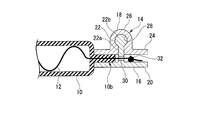
- the caulking member 14 comprises a male member 16 and a female member 18.
- the male member 16 includes a disc-shaped first flat plate portion 20 and a fitting convex portion 22 provided to rise from the central portion of the first flat plate portion 20.
- the fitting convex portion 22 is provided with a trunk 22 a which stands up from the first flat plate portion 20 and a spherical head 22 b provided at the tip of the trunk 22 a.
- the female member 18 includes a disc-shaped second flat plate portion 24 and a protrusion 26 provided on a central portion of the second flat plate 24.
- the fitting recess 28 is formed in the protrusion 26. It is done.
- the fitting recess 28 is opened at the lower surface of the second flat plate portion 24.
- the fitting recess 28 of the female member 18 is such that the head 22 b of the fitting projection 22 of the male member 16 fits therein.
- the fitting convex portion 22 and the fitting concave portion 28 are detachably fitted.
- the fitting convex portion 22 and the tube 10 and the conducting wire 12 are held by the first flat plate portion 20 of the male member 16 and the second flat portion 24 of the female member 18
- the tube 10 and the conductor 12 are crimped and fixed.
- the lead wire and the tube are caulked and fixed by a caulking member as in this example in that the tube and the lead wire can be fixed easily and firmly. More preferably, the lead wire and the tube are crimped by the first flat plate portion and the second flat plate portion of the male member in a state where the male member and the female member of the caulking member are fitted.
- the through hole 30 is formed in the stem 22 a of the fitting convex portion 22 in the male member 16.
- the male member 16 is formed in a state where a portion of the lead 12 exposed from the tube 10 is passed through the through hole 30 and a knot 32 larger than the through hole 30 is formed in the end portion of the lead 12 passing through the through hole 30.
- the lead 12 and the tube 10 are crimped by the and female member 18.
- the stretchable wire a portion of the conductive wire exposed from the end of the tube is passed through the through hole of the caulking member, and a portion larger than the through hole is formed in the portion passing through the through hole of the conductive wire.
- the tube is crimped.
- the distal end of the conducting wire 12 is passed through the through hole 30 of the fitting projection 22 to form a knot 32, whereby the conducting wire 12 is unexpectedly pulled out when the conducting wire 12 and the tube 10 are fixed.
- the conductor 12 can be stably disposed between the male member 16 and the female member 18. Therefore, fixing of the conducting wire 12 and the tube 10 by the caulking member 14 can be performed more easily, and the yield is improved.
- the material for forming the caulking member 14 is not particularly limited, and examples thereof include metals such as stainless steel (SUS), brass, copper, iron, silver, gold, platinum, aluminum, and tin. If the caulking member 14 is made of metal, it can also be used as a male connector for electrically connecting the caulking member 14 to other members. For example, a snap button can be employed as the caulking member 14.
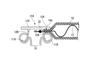
- the caulking member 114 has a ring-shaped male member 116 and a ring-shaped female member 118.
- the resilient female member 118 is crimped to the spike 128 formed on the male member 116 and fixed to the ring-shaped male member 116.
- the ring-shaped male member 116 has a ring-shaped flat plate portion 124.
- the spikes 128 are formed to extend substantially at right angles to the flat plate portion 124.
- the female member 118 is crimped to the male member 116 to press the end 10 a of the tube 10 sandwiched between the flat portion 124 and the flat portion 124. That is, the female member 118 presses the end 10 a of the tube 10 against the flat portion 124 by the spring force of the spike 128 and the female member 116. Thereby, the tube 10 and the conducting wire 12 are fixed by the female member 118 and the flat plate portion 124.
- the lead 12 drawn from the tube 10 forms a knot 32.
- the knot 32 is more centrally located in the ring shaped male member 116 than the spikes 123 and prevents the lead 12 and the tube 10 from coming off the male member 116.
- the ring-shaped female member 118 and the ring-shaped male member 116 are made of metal. Therefore, according to the above configuration, the lead 12 is electrically connected to the female member 118 via the male member 116.
- a recess 51 is formed in the center of the female member 118. The recess 51 engages with the projection 26 of the male connector shown in FIG. 2 to electrically connect the male connector shown in FIG. 5 and the female connector shown in FIG.
- the mode of fixing the tube and the lead wire in the stretchable wiring is not limited to the mode using the caulking member 14.
- the flexible wiring may be one in which the tube and the lead are crimped and fixed by a caulking member in which the through hole 30 is not formed in the male member 16 in the caulking member 14.
- the lead wire and the tube may be squeezed and fixed by the squeeze clamp at one or both of the end portions.
- the tube 10 and the lead 12 may be squeezed and fixed by the squeeze clamp 42 at one or both of the first end 10a and the second end 10b. .
- the squeeze clamp 42 is a rod-like metal fitting, and is annularly deformed so as to squeeze the wire 12 and the tube 10.
- a metal which comprises the squeeze clamp 42 SUS, a brass, iron, and aluminum can be illustrated, for example.
- the metal constituting the throttling stopper 42 may be one type, or two or more types.
- the length and thickness of the squeeze clamp 42 may be set appropriately as long as the wire 12 and the tube 10 can be firmly fixed.
- the lead wire and the tube may be bound and fixed by a band material at one or both of the end portions.
- the tube 10 and the conducting wire 12 are fixed by being wound and bound by the band member 50 at one or both of the first end 10a and the second end 10b. It is also good.
- the band material 50 As a form of the band material 50, what is necessary is to bind and fix a conducting wire and a tube, and, for example, a binding band and a cord can be exemplified.
- the band material 50 1 type may be used independently and 2 or more types may be used together.
- the material for forming the band member 50 is not particularly limited. Examples thereof include polyethylene, polyethylene terephthalate, polyurethane, polystyrene, nylon, polycarbonate, fluorocarbon resin, silicone rubber, and metals such as SUS, brass, iron, and aluminum.
- the length and the thickness of the band material 50 may be set appropriately as long as the wire 12 and the tube 10 can be firmly fixed.
- the stretchable wire may be one that crimps and secures the tube and the lead wire using a crimp terminal.
- Any crimp terminal may be used as long as it can crimp and fix a tube and a conducting wire, and a known crimp terminal generally used for wiring can be adopted.
- one or both of the portions on the first end 10 a side and the second end 10 b side in the longitudinal direction of the tube 10 are connected together with the conducting wire 12 to connect the tube 10 and the conducting wire 12. And may be fixed.
- pin terminals may be inserted into both end portions in the longitudinal direction of the tube, and the portion of the tube into which the pin terminals are inserted may be tied with a strap to fix the tube and the wire. It does not specifically limit as a pin terminal, The well-known crimp terminal normally used for wiring is employable. As an aspect which fixes a tube and conducting wire in elastic wiring, you may combine two or more of the above-mentioned aspects.
- the tube and the lead in addition to the both end portions of the tube, the tube and the lead may be fixed also in portions other than the both end portions in the longitudinal direction of the tube. That is, the number of fixing portions to which the tube and the lead wire in the stretchable wiring are fixed is not limited to two, and may be three or more.
- the composite wiring 100 can be suitably used for wearable biological signal acquisition devices such as belt-type and clothes-type wearable biological electrodes.
- the composite wiring 100 can be used by arranging the extension wiring 110 in a portion where the discomfort does not easily occur at the time of mounting, and relaying the portion which easily causes the discomfort by the stretchable wire 1.
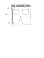
- FIG. 11 is a schematic view in which the composite wiring 100 is fixed to clothes.
- the both ends of the composite wiring 100 respectively connect the transmitter 101 and the sensor 102.
- the clothes may be fixed by any method other than the pants illustrated in FIG. 11, regardless of the types such as mufflers, bandages, socks, etc., which can fix the wiring of the present invention.
- the sensor 102 may be selected from wearable electrodes, a pulse sensor, a thermometer, an accelerometer, and the like as needed, and a plurality of sensors may be used.
- the pulse data measured by the sensor 102 can be transferred to the outside by the transmitter 101.
- the composite wiring 100 may be disposed either inside or outside of the clothes, if it is disposed inside, the wiring will not be visible to the human eye, and the wearer will use it as smartware for acquiring biological data without being aware of the wiring. can do.
- the fixing method and the fixing position of the transmitter 101 and the sensor 102 may be arbitrary.
- the transmitter 101 may be fixed to a pair of pants, and the sensor 102 may be fixed to a sock, etc.
- the elastic wiring and the composite wiring of the present invention by using the SUS yarn as the conducting wire, it is possible to wash the wear to which the composite wiring is applied.
- stretchable wiring and composite embryo property using tubes made of silicone rubber are excellent in heat resistance and chemical resistance, wear to which this composite wiring is applied is also suitable for severe environments as fire resistance and chemical resistance. It can be used.
- the signal acquisition member according to the second aspect of the present invention includes a wire and an electrode connected to a lead included in the wire.
- the lead wire and the electrode are crimped and connected, and the connection portion is sealed in a watertight manner by a sealing material.
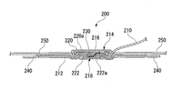
- the signal acquisition member 200 of the present embodiment includes a wire 210, an electrode 212, and a connection member 214.
- the connection portion 218 between the lead wire 216 of the wiring 210 and the electrode 212 is crimped by the connection member 214.
- the wire 210 is not particularly limited, and may be the stretchable wire described in the composite wire, or a known wire other than the stretchable wire. Stretchable wiring is preferable in that the electrode 212 is less likely to be bent after connection of the wiring 210 and noise in signal acquisition can be easily reduced.
- the electrode 212 is not particularly limited, and may be, for example, a conductive polymer electrode immobilized in a state where the conductive polymer is impregnated in the fiber sheet.
- known electrodes other than the conductive polymer electrode may be used.
- the fibers constituting the fiber sheet are not particularly limited, and examples thereof include synthetic fibers such as nylon fibers and polyester fibers, vegetable fibers such as cotton and hemp, and animal fibers such as silk and wool.
- the conductive polymer is not particularly limited, and is a polythiophene-based polymer such as PEDOT (poly (3,4-ethylenedioxythiophene)), polypyrrole, polyaniline, polyacetylene, polyparaphenylene, polyparaphenylenevinylene, Polyfluorene etc. can be illustrated.
- the connecting member 214 includes a pair of first crimping members 220 and a second crimping member 222 each having a U-shaped cross section.
- the first crimping member 220 is one size larger than the second crimping member 222, and the second crimping member 222 is positioned inside the first crimping member 220 when the connection portion 218 of the wire 210 and the electrode 212 is crimped. It is supposed to get in.
- metals such as stainless steel (SUS), brass, copper, iron, silver, gold, platinum, aluminum, tin, can be illustrated, for example. It is preferable that the outer surface 220a of the first pressure bonding member 220 and the outer surface 222a of the second pressure bonding member 222 have an insulating coating.
- the waterproof sheet 240 and the fabric 250 are stacked in this order on the electrode 212 so that the surface of the electrode 212 is partially exposed, and the conductive wire 216 drawn from the wiring 210 is in contact with the exposed surface of the electrode 212. ing. Then, in this state, the first crimping member 220 and the second crimping member 222 are crimped and caulked from above and below, whereby the connection portion 218 of the wiring 210 and the electrode 212 is formed.
- connection portion 218 crimped by the connection member 214 is sealed in a watertight manner by the sealing material 230.
- the sealing material 230 is filled on the electrode 212 around the contact portion between the lead wire 216 of the wiring 210 and the electrode 212 inside the first crimping member 220 of the connection member 214.
- the connection portion 218 of the lead wire 216 of the wiring 210 and the electrode 212 is sealed in a watertight manner.
- the connection portion 218 between the wiring 210 and the electrode 212 is excellent in waterproofness.
- a silicone sealing material is preferable.
- any material that is insulating and waterproof can be used, and examples thereof include polyethylene terephthalate, polyvinyl chloride, polyethylene, and polypropylene.
- the waterproof sheet 240 you may use the vapor deposition film which vapor-deposited metals, such as aluminum, silver, copper.
- Step (x) a step of supplying the sealing material 230 to the contact portion between the lead wire 216 of the wiring 210 and the electrode 212.
- the waterproof sheet 240 and the fabric 250 are superimposed in this order on the electrode 212 so that the surface of the electrode 212 is partially exposed.
- the sealing material 230 is supplied to the portion of the conducting wire 216 drawn from the wiring 210. Then, the lead wire 216 of the wiring 210 is brought into contact with the exposed portion of the surface of the electrode 212. Alternatively, after the lead wire 216 of the wiring 210 is brought into contact with the exposed portion of the surface of the electrode 212, the sealing material 230 may be supplied to the contact portion.
- the first crimping member 220 of the connection member 214 is disposed on the upper side of the contact portion of the electrode 212 and the conducting wire 216 of the wire 210, and the contact portion of the electrode 212 on the lower side of the electrode 212 and the conducting wire 216 of the wire 210
- the second pressure bonding member 222 is disposed at a position corresponding to.
- the first crimping member 220 and the second crimping member 222 are pressed from above and below to be crimped, and the electrode 212 and the lead wire 216 of the wiring 210 are crimped to form the connection portion 218.
- Step (x) and the step (y) is not limited to the order of performing the step (x) and then the step (y).
- Step (x) may be performed after y).
- the sealing material 140 may be supplied from the periphery of the connection portion 218 to seal in a watertight manner.
- connection between the conductive wire and the electrode included in the wire by the connection member may also serve as fixing of the conductive wire and the tube at the end of the stretchable wire. As a result, the number of working processes is reduced, thereby improving the productivity of the signal acquisition member.
- the signal acquisition member 200 can be particularly suitably used for a wearable biological signal acquisition device such as a wearable biological electrode.
- a wearable biological signal acquisition device such as a wearable biological electrode.
- the application of the signal acquisition member of the present invention is not limited to a wearable biological signal acquisition device.
- the signal acquisition member of the present invention As described above, in the signal acquisition member of the present invention, the lead wire of the wiring and the electrode are crimped and connected by the connection member, and the connection portion is sealed in a watertight manner by the sealing material. Therefore, the signal acquisition member of the present invention is excellent in waterproofness of the connection portion between the wiring and the electrode.
- the signal acquisition member of the present invention is not limited to the above-described signal acquisition member 200.
- the cloth or the waterproof sheet may not be disposed at the connection portion.
Landscapes
- Health & Medical Sciences (AREA)
- Life Sciences & Earth Sciences (AREA)
- Engineering & Computer Science (AREA)
- Surgery (AREA)
- General Health & Medical Sciences (AREA)
- Biophysics (AREA)
- Biomedical Technology (AREA)
- Heart & Thoracic Surgery (AREA)
- Medical Informatics (AREA)
- Molecular Biology (AREA)
- Physics & Mathematics (AREA)
- Animal Behavior & Ethology (AREA)
- Pathology (AREA)
- Public Health (AREA)
- Veterinary Medicine (AREA)
- Physiology (AREA)
- Computer Networks & Wireless Communication (AREA)
- Connections Effected By Soldering, Adhesion, Or Permanent Deformation (AREA)
- Insulated Conductors (AREA)
- Measurement And Recording Of Electrical Phenomena And Electrical Characteristics Of The Living Body (AREA)
- Professional, Industrial, Or Sporting Protective Garments (AREA)
- Manufacturing Of Electrical Connectors (AREA)
- Details Of Indoor Wiring (AREA)
Abstract
複合配線は、伸縮性を有するチューブと、前記チューブの中に配置された導線と、前記チューブの長さ方向の両端において前記導線と前記チューブとを固定する固定部とを備え、前記チューブを伸長していない状態における前記固定部の間の長さは、前記導線の方が前記チューブよりも長い伸縮性配線と;前記伸縮性配線以外の他の配線と;前記伸縮性配線の導線と前記他の配線の導線とを互いに接触させた状態でかしめて接続し、かつ内部がシール材で水密に封じられた接続部材とを有する。
Description
本発明は、複合配線、信号取得部材、及びそれらの製造方法に関する。
本願は、2017年11月15日に、日本に出願された特願2017-220480号に基づき優先権を主張し、その内容をここに援用する。
本願は、2017年11月15日に、日本に出願された特願2017-220480号に基づき優先権を主張し、その内容をここに援用する。
心臓発作、骨格筋の痙攣クランピング、癲癇等による痙攣発作等が起きた場合には迅速な対応が求められる。また、近年ではリハビリや健康増進のため、中高齢者がプールや温泉施設等で運動する機会が増えていることから、運動中の事故に迅速に対応することも求められる。このような発作や事故等を検知する方法としては、ベルト型や服型のウエアラブル生体電極等のウエアラブルな生体信号取得機器を用いて心電図や筋電図等の生体信号を取得する方法がある(非特許文献1)。また、近年では、ウエアラブルな生体信号取得機器がスポーツ科学の分野でも利用されており、重要な役割を果たしている。例えば水着型のウエアラブル生体電極を用いて、泳いでいる間の筋電図等の生体信号を取得することが行われている。
ウエアラブルな生体信号取得機器においては、配線と配線の接続部や、配線と電極の接続部の防水が不充分であると、発汗や水濡れによる電解質溶液の進入により配線や電極の短絡や絶縁性の低下が生じ、信号の喪失や信号の減衰の原因となる。また洗濯中や水泳中等に接続部から配線内に水が入り、次にウエアを着るときに配線内に残留した水が接続部から出てきて不快に感じることがある。さらに、配線に銅線やスズメッキ銅線等を用いた場合、接続部の防水が不充分であると接触抵抗の増大による信号取得性能の低下や、緑青によりウエアの生地への変色を生じる場合がある。
NTT技術ジャーナル 26(11), 16-20, 2014-11「ウェアラブル電極インナー技術の応用展開」
本発明は、配線同士の接続部の防水性に優れた複合配線、配線と電極の接続部の防水性に優れた信号取得部材、及びそれらの製造方法を提供することを目的とする。
本発明の一実施形態の複合配線は、伸縮性を有するチューブと、前記チューブの中に配置された導線と、前記チューブの長さ方向の両端において前記導線と前記チューブとを固定する固定部とを備え、前記チューブを伸長していない状態における前記固定部の間の長さは、前記導線の方が前記チューブよりも長い伸縮性配線と;前記伸縮性配線以外の他の配線と:前記伸縮性配線の導線と前記他の配線の導線とを互いに接触させた状態でかしめて接続し、かつ内部がシール材で水密に封じられた接続部材とを有する。
本発明の一実施形態の複合配線において、前記接続部材は圧着スリーブであり、前記圧着スリーブは前記伸縮性配線の前記チューブの端部に挿入された前記他の配線の導線を前記伸縮性配線の前記チューブの周囲からかしめて前記前記伸縮性配線の導線と前記他の配線の導線とを接続するようにしてもよい。
本発明の一実施形態の複合配線において、前記シール材は非硬化型の弾性シール材であってもよい。
本発明の一実施形態の複合配線において、前記固定部はかしめ部材からなり、前記かしめ部材が、第1平板部及び前記第1平板部に設けられた嵌合凸部を備える雄部材と、第2平板部及び前記第2平板部に設けられた嵌合凹部を備える雌部材とを有し、前記嵌合凸部と前記嵌合凹部とを嵌合させた状態で、前記導線と前記チューブとが前記第1平板部と前記第2平板部とでかしめられるとともに、前記雌部材に突起部が形成されてもよい。
本発明の一実施形態の複合配線において、前記固定部はかしめ部材からなり、前記かしめ部材が、平板部および前記平板部からほぼ直角に延びるスパイクを有する雄部材と、前記スパイクと圧着されることによって前記雄部材に固定されるリング状の雌部材とを有し、前記雌部材を前記雄部材に固定させることによって、前記導線と前記チューブとが前記平板部と前記雌部材とでかしめられるとともに、前記雌部材のリング状の中央部に凹み部が形成されてもよい。
本発明の一実施形態の複合配線の製造方法は、前記伸縮性配線の導線と前記他の配線の導線とが接触する部分に前記シール材を供給する工程と、前記接続部分をかしめる工程とを有する。
本発明の一実施形態の信号取得部材は、配線と、前記配線が有する導線にかしめられて接続された電極とを備え、前記導線と前記電極との接続部がシール材で水密に封じられている。
本発明の一実施形態の信号取得部材の製造方法は、前記導線と前記電極との接触部分に前記シール材を供給する工程と、前記接触部分をかしめて前記接続部を形成する工程とを有する。
本発明の一実施形態の複合配線において、前記接続部材は圧着スリーブであり、前記圧着スリーブは前記伸縮性配線の前記チューブの端部に挿入された前記他の配線の導線を前記伸縮性配線の前記チューブの周囲からかしめて前記前記伸縮性配線の導線と前記他の配線の導線とを接続するようにしてもよい。
本発明の一実施形態の複合配線において、前記シール材は非硬化型の弾性シール材であってもよい。
本発明の一実施形態の複合配線において、前記固定部はかしめ部材からなり、前記かしめ部材が、第1平板部及び前記第1平板部に設けられた嵌合凸部を備える雄部材と、第2平板部及び前記第2平板部に設けられた嵌合凹部を備える雌部材とを有し、前記嵌合凸部と前記嵌合凹部とを嵌合させた状態で、前記導線と前記チューブとが前記第1平板部と前記第2平板部とでかしめられるとともに、前記雌部材に突起部が形成されてもよい。
本発明の一実施形態の複合配線において、前記固定部はかしめ部材からなり、前記かしめ部材が、平板部および前記平板部からほぼ直角に延びるスパイクを有する雄部材と、前記スパイクと圧着されることによって前記雄部材に固定されるリング状の雌部材とを有し、前記雌部材を前記雄部材に固定させることによって、前記導線と前記チューブとが前記平板部と前記雌部材とでかしめられるとともに、前記雌部材のリング状の中央部に凹み部が形成されてもよい。
本発明の一実施形態の複合配線の製造方法は、前記伸縮性配線の導線と前記他の配線の導線とが接触する部分に前記シール材を供給する工程と、前記接続部分をかしめる工程とを有する。
本発明の一実施形態の信号取得部材は、配線と、前記配線が有する導線にかしめられて接続された電極とを備え、前記導線と前記電極との接続部がシール材で水密に封じられている。
本発明の一実施形態の信号取得部材の製造方法は、前記導線と前記電極との接触部分に前記シール材を供給する工程と、前記接触部分をかしめて前記接続部を形成する工程とを有する。
本発明によれば、配線同士の接続部の防水性に優れた複合配線、及び、配線と電極の接続部の防水性に優れた信号取得部材が得られる。
以下の説明において例示される図の寸法等は一例であって、本発明はそれらに必ずしも限定されるものではなく、その要旨を変更しない範囲で適宜変更して実施することが可能である。
[複合配線]
本発明の第1の態様である複合配線は、後述の伸縮性配線と、伸縮性配線以外の延長配線(他の配線)とを備え、伸縮性配線の導線と、延長配線の導線とが互いに接触した状態でかしめられて接続され、かつその接続部がシール材で水密に封じられている複合配線である。伸縮性配線は、伸縮性を有するチューブ内に導線が配置され、チューブを延伸していない状態における導線の固定部間の長さがチューブの固定部間の長さよりも長くなるように、チューブの長さ方向の両端部分のそれぞれで導線とチューブとが固定されている配線である。
本発明の第1の態様である複合配線は、後述の伸縮性配線と、伸縮性配線以外の延長配線(他の配線)とを備え、伸縮性配線の導線と、延長配線の導線とが互いに接触した状態でかしめられて接続され、かつその接続部がシール材で水密に封じられている複合配線である。伸縮性配線は、伸縮性を有するチューブ内に導線が配置され、チューブを延伸していない状態における導線の固定部間の長さがチューブの固定部間の長さよりも長くなるように、チューブの長さ方向の両端部分のそれぞれで導線とチューブとが固定されている配線である。
以下、本発明の第1の態様の複合配線について、一例を示して説明する。
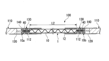
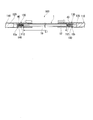
本実施形態の複合配線100は、図1及び図2に示すように、伸縮性配線1と、伸縮性配線1以外の延長配線(他の配線)110と、接続部材40と、カバー部材120,120とを備えている。複合配線100では、伸縮性配線1と延長配線110との接続部130がそれぞれ接続部材40によってかしめられている。
本実施形態の複合配線100は、図1及び図2に示すように、伸縮性配線1と、伸縮性配線1以外の延長配線(他の配線)110と、接続部材40と、カバー部材120,120とを備えている。複合配線100では、伸縮性配線1と延長配線110との接続部130がそれぞれ接続部材40によってかしめられている。
伸縮性配線1は、チューブ10と、導線12とを備えている。
導線12は、チューブ10の長さ方向の第1端部10aから第2端部10bまで到達するようにチューブ10内に配置されている。伸縮性配線1においては、チューブ10の長さ方向の第1端部10a側と第2端部10b側の両端部分のそれぞれで、導線12とチューブ10とが接続部材40によってかしめられて固定されている。この例では、接続部材40が、伸縮性配線1と延長配線110とをかしめて接続する役割と、伸縮性配線1において導線12とチューブ10とをかしめて固定する役割を兼ねている。
導線12は、チューブ10の長さ方向の第1端部10aから第2端部10bまで到達するようにチューブ10内に配置されている。伸縮性配線1においては、チューブ10の長さ方向の第1端部10a側と第2端部10b側の両端部分のそれぞれで、導線12とチューブ10とが接続部材40によってかしめられて固定されている。この例では、接続部材40が、伸縮性配線1と延長配線110とをかしめて接続する役割と、伸縮性配線1において導線12とチューブ10とをかしめて固定する役割を兼ねている。
チューブ10は、伸縮性を有する。すなわち、チューブ10は、長さ方向に荷重をかけて引き伸ばしたときに破断しにくく、前記荷重を取り去って収縮した後の残留変位が少ないチューブである。チューブ10の伸縮性は、チューブ10の材質及び厚さにより調節できる。
チューブ10を形成する材料としては、伸縮性を有する絶縁材料を使用でき、例えば、シリコーンゴム、ウレタンゴム、天然ゴム、イソプレンゴム、ブタジエンゴム、スチレン・ブタジエンゴム、クロロプレンゴム、ニトリルゴム、ポリイソブチレン、エチレンプロピレンゴム、クロロスルホン化ポリエチレン、アクリルゴム、フッ素ゴム、エピクロルヒドリンゴム等の各種エラストマーを例示できる。チューブ10を形成する材料としては、耐熱性の点から、シリコーンゴムが好ましい。チューブ10を形成する材料としては、1種を単独で使用してもよく、2種以上を組み合わせて使用してもよい。
チューブ10の破断点伸度は、25~300%が好ましく、50~150%がより好ましい。チューブ10の破断点伸度が前記範囲の下限値以上であれば、伸縮性配線1の伸縮性が向上し、違和感がより小さくなる。チューブ10の破断点伸度が前記範囲の上限値以下であれば、着替えの際に生地の引き延ばしに伴って配線に加わるストレスに伴う配線の断裂や短絡を回避できる。
なお、チューブの破断点伸度は、JIS K-7127(1999)に準拠して測定される。
なお、チューブの破断点伸度は、JIS K-7127(1999)に準拠して測定される。
チューブ10の内径及び外径は、特に限定されず、チューブ10内に導線12を配置できるように適宜設定すればよい。例えば、チューブ10の内径を0.1~10mm、外径を0.2~12mmとすることができる。
チューブ10の厚さは、0.1~1mmが好ましく、0.2~0.6mmがより好ましい。チューブ10の厚さが前記範囲の下限値以上であれば、充分な強度が得られやすい。
チューブ10の厚さが前記範囲の上限値以下であれば、優れた伸縮性が得られやすい。
チューブ10の厚さが前記範囲の上限値以下であれば、優れた伸縮性が得られやすい。
導線12を形成する材料としては、導線に一般的に使用される材料を使用でき、例えば、ステンレス鋼(SUS)、エナメル、金、プラチナ、イリジウムを例示できる。なかでも、導線12を形成する材料としては、錆びにくく、耐熱性に優れ、ウエアに適用した際に丸洗いが可能となる点から、SUSが好ましい。導線12を形成する材料は、1種であってもよく、2種以上であってもよい。
本発明では、シリコーンゴムで形成されたチューブと、SUS糸で形成された導線の組み合わせが特に好ましい。
本発明では、シリコーンゴムで形成されたチューブと、SUS糸で形成された導線の組み合わせが特に好ましい。
導線12の形態としては、特に限定されず、例えば、単繊維の形態であってもよく、複数の繊維を撚り合わせた撚り糸の形態であってもよい。なかでも、延伸していない状態においてチューブ10内で導線12が螺旋状となって絡まりにくく、より安定して存在でき、伸縮性配線1の伸縮がスムーズになる点から、導線12は撚り糸の形態であることが好ましい。
導線12の太さは、適宜設定でき、例えば、0.01~10mmとすることができる。
なお、導線12が複数の線からなる撚り糸の場合その外径を導線12の太さとする。
なお、導線12が複数の線からなる撚り糸の場合その外径を導線12の太さとする。
導線12の表面には絶縁コートが施されていてもよい。導線12の表面が絶縁コートされていることで、伸縮に伴うインピーダンス変化が低減される。絶縁コートに使用する絶縁材料としては、公知ものを使用でき、例えば、ポリウレタン、ポリエステルイミド、ポリアミドイミド、ポイイミド、PVC(ポリ塩化ビニル混合物)、PE(ポリエチレン)フッ素樹脂、TUFRET(タフレット)、ゴムを例示できる。絶縁コートの方法としては、公知の方法を採用できる。
導線12には、シリコーンオイル等の潤滑材、防錆材が塗布されていてもよい。
導線12には、シリコーンオイル等の潤滑材、防錆材が塗布されていてもよい。
伸縮性配線1においては、チューブ10を延伸していない状態における、導線12の固定部間の長さL1がチューブ10の固定部間の長さL2よりも長くなるように、導線12がチューブ10内に配置されて固定されている。
なお、導線12の固定部間の長さL1は、図3に示すように、チューブ10を長さ方向に引っ張って延伸し、導線12を直線状に緊張させた状態における、両端部分の接続部材40による固定部同士との距離と一致する。
なお、導線12の固定部間の長さL1は、図3に示すように、チューブ10を長さ方向に引っ張って延伸し、導線12を直線状に緊張させた状態における、両端部分の接続部材40による固定部同士との距離と一致する。
前記した導線12の固定部間の長さL1がチューブ10の固定部間の長さL2よりも長いことで、チューブ10を延伸していない状態においては、チューブ10内において導線12が螺旋状やジグザグ状等のように湾曲や屈曲を有する形状になっている。このように、導線12自体は実質的に伸縮性がなくても、導線12はチューブ10内で湾曲や屈曲により緊張せず、長さ方向の延伸を許容できる余裕を有している。そのため、伸縮性配線1は、図3に示すように導線12が直線状となるまで引っ張って延伸でき、引っ張りの荷重を解放すると図1のようにチューブ10の伸縮性により収縮する。
また、伸縮性配線1の伸縮では、導線12が湾曲や屈曲のある形状となったり直線状になったりするだけであるため、例えばエラストマーに導電材を混入させた導線等に比べて、伸縮に伴う導線12のインピーダンス変動が少ない。
また、伸縮性配線1の伸縮では、導線12が湾曲や屈曲のある形状となったり直線状になったりするだけであるため、例えばエラストマーに導電材を混入させた導線等に比べて、伸縮に伴う導線12のインピーダンス変動が少ない。
チューブ10を延伸していない状態におけるチューブ10の固定部間の長さL2に対する導線12の固定部間の長さL1の比L1/L2は、1.1~5が好ましく、1.2~2.5がより好ましい。比L1/L2が前記範囲の下限値以上であれば、優れた伸縮性が得られやすく、違和感がより小さくなる。比L1/L2が前記範囲の上限値以下であれば、伸縮性配線1の製造が容易であり、生産性が高くなる。
チューブ10内の導線12の周囲は、空気が存在している状態であってもよく、液体が充填されている状態であってもよいが、伸縮性配線1の製造が容易な点から、空気が存在している状態が好ましい。
チューブ10内の導線12の周囲に充填する液体としては、チューブ10内での導線12の動きを阻害せず、導線12を劣化させないものであればよく、例えば、油性オイル、シリコーンオイル、グリセリン、グリセロール等を例示できる。
チューブ10内の導線12の周囲に充填する液体としては、チューブ10内での導線12の動きを阻害せず、導線12を劣化させないものであればよく、例えば、油性オイル、シリコーンオイル、グリセリン、グリセロール等を例示できる。
より具体的には、チューブ10として外径2mm、壁厚約0.2mmのシリコンチューブを用い、導線12として長さ約140cmのSUS(Steel Use Stainless)線を用いた例について説明する。SUS線(SUS304)の太さは12μm、質量0.22g/mである。このSUS線にシリコンチューブを被膜し、シリコンチューブとSUS線との両端を固定し、チューブおよびSUS線の長さが約50%になるように収縮させた。
このようにして得られた伸縮性配線1は、張力をかけない状態で線径2.5mm、長さ60cmであった。この伸縮性配線1に長さ方向に張力をかけ、完全に伸長させたときの長さは136cmであった。この伸縮性配線1が伸長を開始するときの張力(初動感度)は、0.03ニュートン(N)であり、完全に伸長させるのに要する張力(最大伸長時張力)は1.2Nであった。この伸縮性配線1のSUS線の直流抵抗値は30.5Ωであり、伸縮にともなう抵抗値の変化は見られなかった。この伸縮性配線1を完全に伸長させた後、張力を解除すると、線径2.5mm、長さ60cmに戻った。
このようにして得られた伸縮性配線1は、張力をかけない状態で線径2.5mm、長さ60cmであった。この伸縮性配線1に長さ方向に張力をかけ、完全に伸長させたときの長さは136cmであった。この伸縮性配線1が伸長を開始するときの張力(初動感度)は、0.03ニュートン(N)であり、完全に伸長させるのに要する張力(最大伸長時張力)は1.2Nであった。この伸縮性配線1のSUS線の直流抵抗値は30.5Ωであり、伸縮にともなう抵抗値の変化は見られなかった。この伸縮性配線1を完全に伸長させた後、張力を解除すると、線径2.5mm、長さ60cmに戻った。
上記の通り、この伸縮性配線1は、小さい張力で伸長させることができる。したがって、この伸縮性配線1は、被験者が衣類とともに装着したときに、ゴム紐のように違和感なく伸長する。この伸縮性配線1は、ウエラブル配線として使用する場合に体の動きとともに伸長したときに、接続された生体電極に張力を及ぼさない。したがって、生体電極が装着された位置からズレることがなく、生体電極から得られる信号の歪が発生しにくい。
この伸縮性配線1の線径は2.5mmであり、従来のケーブルと比較して細い。また、この伸縮性配線1は、チューブとしてシリコンチューブを使用しているため、柔軟であり、肌触りがよい。伸縮性配線1を衣類に装着して、直接皮膚にあたっても違和感を生じにくく、長期間の生体計測に適している。シリコンとSUS線とを用いた伸縮性配線1は、熱に対しても薬品に対しても強く、洗濯機で丸洗いが可能であり、乾燥機やドライヤーで乾燥することもできる。
この伸縮性配線1の線径は2.5mmであり、従来のケーブルと比較して細い。また、この伸縮性配線1は、チューブとしてシリコンチューブを使用しているため、柔軟であり、肌触りがよい。伸縮性配線1を衣類に装着して、直接皮膚にあたっても違和感を生じにくく、長期間の生体計測に適している。シリコンとSUS線とを用いた伸縮性配線1は、熱に対しても薬品に対しても強く、洗濯機で丸洗いが可能であり、乾燥機やドライヤーで乾燥することもできる。
延長配線(他の配線)110としては、特に限定されず、公知の配線を使用することができる。延長配線110は、導線112として銅線、スズメッキ銅線を用いた導線であってもよい。
複合配線100では、伸縮性配線1の導線12と、延長配線110の導線112とが互いに接触した状態で接続部材40によってかしめられて接続されている。また、接続部材40でかしめられた接続部130は、シール材140で水密に封じられている。
具体的には、この例では、図2に示すように、延長配線110から引き出された導線112が、伸縮性配線1のチューブ10内に第1端部10a側から挿入されて、伸縮性配線1の導線12と延長配線110の導線112とが接触されている。そして、接続部130において、チューブ10内の伸縮性配線1の導線12と延長配線110の導線112の周囲にシール材140が充填されることで水密に封じられている。これにより、接続部130は防水性が優れたものになっている。
接続部材40としては、伸縮性配線1の導線12と延長配線110の導線112とをかしめて接続できるものであればよく、公知の圧着端子を使用することができる。なかでも、接続部材40としては、圧着チューブ(圧着スリーブ)が好ましい。
この例では、接続部材40として圧着チューブ(圧着スリーブ)を使用しており、接続部材40内で伸縮性配線1の導線12と延長配線110の導線112とが接触され、接続部材40が部分的に押し潰されて圧着されることで、伸縮性配線1のチューブ10ごとかしめられて接続部130が形成されている。本発明では、このように、圧着チューブ内で、伸縮性配線のチューブの端部内に延長配線の導線が挿入されて、伸縮性配線の導線と延長配線の導線とが互いに接触され、圧着チューブにより伸縮性配線のチューブごとかしめられて接続部が形成されていることが好ましい。これにより、伸縮性配線と延長配線の接続部の防水性がより優れたものとなる。
シール材140としては、防水性を確保できるシール材であれば特に限定されないが、固まった後でも伸縮性配線1の動きに追従しやすく、亀裂や隙間等が生じて防水性が低下することを抑制しやすい点から、非硬化型の弾性シール材であることが好ましい。
弾性シール材を形成する材料としては、例えば、シリコーン、フッ素ゴム等のゴム、ポリエチレン、酢酸樹脂エマルジョンを例示できる。
弾性シール材を形成する材料としては、例えば、シリコーン、フッ素ゴム等のゴム、ポリエチレン、酢酸樹脂エマルジョンを例示できる。
シール材140は、作業性の点から、液状の状態で接続部130に供給した後に固まるものが好ましい。また、伸縮性配線1の伸縮性を保ちやすい点では、チューブ10内においてシール材140ができるだけ接続部130近傍にとどまり、接続部130よりも長さ方向の中央部側にできるだけシール材140が広がらないようにすることが好ましい。この点では、液状の状態における粘度がある程度高いシール材を使用することが好ましい。
シール材140としては、シリコーンシール材が特に好ましい。
シール材140としては、シリコーンシール材が特に好ましい。
伸縮性配線1と延長配線110との接続部130の周辺は、カバー部材120,120を設けて覆い隠すことが好ましい。これにより、複合配線100の接続部130の周辺がウエアの生地等に引っ掛かる等の不具合を抑制しやすく、また複合配線100の外観も良好になる。
カバー部材120としては、伸縮性配線1と延長配線110の接続部130周辺を隠せるものであればよく、例えば、熱収縮チューブ、シリコーンチューブ等のチューブを例示できる。また、カバー部材120は必ずしも延長配線110の接続部130周辺を広く覆う必要はなく、絶縁性の材料で表面を被覆した接続部材40によっても接続部130をカバーできる。
カバー部材120としては、伸縮性配線1と延長配線110の接続部130周辺を隠せるものであればよく、例えば、熱収縮チューブ、シリコーンチューブ等のチューブを例示できる。また、カバー部材120は必ずしも延長配線110の接続部130周辺を広く覆う必要はなく、絶縁性の材料で表面を被覆した接続部材40によっても接続部130をカバーできる。
複合配線100の製造方法としては、下記の工程(a)、(b)を有する方法が挙げられる。
工程(a):伸縮性配線1の導線12と延長配線110の導線112の接触部分にシール材140を供給する工程。
工程(b):伸縮性配線1の導線12と延長配線110の導線112の接触部分をかしめて接続部130を形成する工程。
工程(a):伸縮性配線1の導線12と延長配線110の導線112の接触部分にシール材140を供給する工程。
工程(b):伸縮性配線1の導線12と延長配線110の導線112の接触部分をかしめて接続部130を形成する工程。
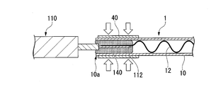
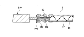
工程(a)では、例えば、図4Aに示すように、チューブ10の第1端部10a側を接続部材40内に通し、接続部材40を取り付けた部分のチューブ10内にシール材140を充填する。このとき、接続部材40とチューブ10との隙間にもシール材140が充填されてもよい。
次いで、図4Bに示すように、チューブ10のシール材140が充填された部分に、延長配線110から引き出した導線112を挿し込み、伸縮性配線1の導線12と延長配線110の導線112とを接触させる。
次いで、図4Bに示すように、チューブ10のシール材140が充填された部分に、延長配線110から引き出した導線112を挿し込み、伸縮性配線1の導線12と延長配線110の導線112とを接触させる。
工程(b)では、図4Bに示すように、例えば圧着工具等で接続部材40を部分的に押し潰し、チューブ10ごと伸縮性配線1の導線12と延長配線110の導線112をかしめる。これにより、図4Cに示すように、シール材140で水密に封じられた状態で伸縮性配線1の導線12と延長配線110の導線112がかしめられて接続された接続部130が形成される。
接続部130を形成した後、図2に示すように、カバー部材120を取り付けて接続部130の周辺を覆い隠す。
接続部130を形成した後、図2に示すように、カバー部材120を取り付けて接続部130の周辺を覆い隠す。
また、伸縮性配線1におけるチューブ10の第2端部10b側においても、同様に工程(a)及び工程(b)を実施して接続部130を形成し、伸縮性配線1と延長配線110とを接続する。第2端部10b側の接続は、図3に示すように、チューブ10に長さ方向に引っ張る荷重をかけ、チューブ10を延伸した状態で実施する。接続後にチューブ10を引っ張る荷重を解放することで、チューブ10が延伸していない元の状態に戻り、図1に示すような複合配線100が得られる。
なお、工程(a)と工程(b)の順序は、工程(a)を行ってから工程(b)を行う順序には限定されず、工程(b)を行ってから工程(a)を行ってもよい。例えば、伸縮性配線1の導線12と延長配線110の導線112の接触部分を接続部材40によってかしめた後に、接触部分にシール材140を塗布等により供給して接続部130を水密に封じてもよい。
以上説明したように、本発明の複合配線においては、伸縮性配線の導線と延長配線(他の配線)の導線とが互いに接触した状態でかしめられて接続され、かつその接続部がシール材で水密に封じられている。そのため、本発明の複合配線は、伸縮性配線の導線と延長配線の接続部の防水性に優れている。
なお、本発明の複合配線は、前記した複合配線100には限定されない。
複合配線100では伸縮性配線1の両側がそれぞれ延長配線110と接続されているが、例えば、伸縮性配線1におけるチューブ10の第1端部10a側だけを延長配線110と接続し、チューブ10の第2端部10b側は延長配線110と接続されていないものであってもよい。
複合配線100では伸縮性配線1の両側がそれぞれ延長配線110と接続されているが、例えば、伸縮性配線1におけるチューブ10の第1端部10a側だけを延長配線110と接続し、チューブ10の第2端部10b側は延長配線110と接続されていないものであってもよい。
本発明の複合配線が備える伸縮性配線の数は、1本には限定されず、2本以上であってもよい。本発明の複合配線が備える延長配線(他の配線)の数は、2本には限定されず、1本であってもよく、3本以上であってもよい。本発明の複合配線における伸縮性配線と延長配線(他の配線)の数は、用途等に応じて適宜設定できる。
また伸縮性配線1の一方の側の端部を延長配線110と接続しない場合に、伸縮性配線の延長配線と接続しない端部では接続部材40を用いずに導線12とチューブ10とを固定する。伸縮性配線と延長配線とを接続する接続部材を用いずに、伸縮性配線の両端部分の一方又は両方において導線とチューブを固定する態様としては、例えば、図5に例示したかしめ部材14を用いる態様が挙げられる。
かしめ部材14は、雄部材16と雌部材18とを備えている。
雄部材16は、円板状の第1平板部20と、第1平板部20の中央部から立ち上がるように設けられた嵌合凸部22とを備えている。嵌合凸部22は、第1平板部20から立ち上がる幹部22aと、幹部22aの先端に設けられた球状の頭部22bとを備えている。
かしめ部材14は、雄部材16と雌部材18とを備えている。
雄部材16は、円板状の第1平板部20と、第1平板部20の中央部から立ち上がるように設けられた嵌合凸部22とを備えている。嵌合凸部22は、第1平板部20から立ち上がる幹部22aと、幹部22aの先端に設けられた球状の頭部22bとを備えている。
雌部材18は、円板状の第2平板部24と、第2平板部24の中央部上に設けられた突起部26とを備えており、突起部26内には嵌合凹部28が形成されている。嵌合凹部28は、第2平板部24の下面で開口している。雌部材18の嵌合凹部28は、雄部材16の嵌合凸部22の頭部22bが嵌まり込むようになっている。
このように、雄部材16と雌部材18とは、嵌合凸部22と嵌合凹部28とが着脱自在に嵌合するようになっている。
このように、雄部材16と雌部材18とは、嵌合凸部22と嵌合凹部28とが着脱自在に嵌合するようになっている。
例えばチューブ10の第2端部10b側において、雄部材16の第1平板部20と雌部材18の第2平板部24でチューブ10と導線12とが挟持されるように嵌合凸部22と嵌合凹部28とが嵌合されることで、チューブ10と導線12とがかしめられて固定される。
チューブと導線とを簡便にしっかりと固定できる点では、この例のように、導線とチューブとがかしめ部材によりかしめられて固定されていることが好ましい。また、かしめ部材の雄部材と雌部材を嵌合させた状態で、雄部材の第1平板部と第2平板部によって導線とチューブがかしめられることがより好ましい。
チューブと導線とを簡便にしっかりと固定できる点では、この例のように、導線とチューブとがかしめ部材によりかしめられて固定されていることが好ましい。また、かしめ部材の雄部材と雌部材を嵌合させた状態で、雄部材の第1平板部と第2平板部によって導線とチューブがかしめられることがより好ましい。
また、この例では、雄部材16における嵌合凸部22の幹部22aに貫通孔30が形成されている。導線12のチューブ10から露出した部分が貫通孔30に通され、さらに導線12の貫通孔30を通過した末端側の部分に貫通孔30よりも大きい結び目32が形成された状態で、雄部材16と雌部材18により導線12とチューブ10とがかしめられている。
このように、伸縮性配線においては、導線のチューブの端部から露出した部分をかしめ部材の貫通孔に通し、導線の貫通孔を通過した部分に貫通孔よりも大きい結び目を形成した状態で導線とチューブをかしめることが好ましい。
本実施形態のように導線12の末端側を嵌合凸部22の貫通孔30に通して結び目32を形成することで、導線12とチューブ10とを固定する際に導線12が予期せず抜けることを抑制でき、雄部材16と雌部材18の間に導線12を安定して配置できる。そのため、かしめ部材14による導線12とチューブ10の固定をより簡便に行うことができ、歩留まりが向上する。
本実施形態のように導線12の末端側を嵌合凸部22の貫通孔30に通して結び目32を形成することで、導線12とチューブ10とを固定する際に導線12が予期せず抜けることを抑制でき、雄部材16と雌部材18の間に導線12を安定して配置できる。そのため、かしめ部材14による導線12とチューブ10の固定をより簡便に行うことができ、歩留まりが向上する。
かしめ部材14を形成する材料としては、特に限定されず、例えば、ステンレス(SUS)、真鍮、銅、鉄、銀、金、白金、アルミニウム、錫等の金属を例示できる。かしめ部材14を金属製とすることで、かしめ部材14を他の部材と電気的に接続する雄コネクタとしても使用できる。
かしめ部材14としては、例えば、スナップボタンを採用できる。
かしめ部材14としては、例えば、スナップボタンを採用できる。
伸縮性配線1の一方の側の端部を延長配線110と接続しない場合に、上述したようにかしめ部材14を雄コネクタとするほかに、以下に説明するように、かしめ部材を雌コネクタとして使用することもできる。
すなわち、図10を参照すると、かしめ部材114は、リング状雄部材116とリング状の雌部材118とを有する。ばね性を有する雌部材118は、雄部材116に形成されたスパイク128に圧着されてリング状雄部材116に固定される。リング状雄部材116は、リング状の平板部124を有する。スパイク128は、平板部124に対してほぼ直角に延びるように形成される。雌部材118は、雄部材116にかしめられることによって、平板部124との間に挟まれたチューブ10の端部10aを平坦部124に圧接する。すなわち、雌部材118は、スパイク128と雌部材116とのばね力によってチューブ10の端部10aを平坦部124に圧接する。これにより、チューブ10と導線12とが雌部材118および平板部124によって固定される。
すなわち、図10を参照すると、かしめ部材114は、リング状雄部材116とリング状の雌部材118とを有する。ばね性を有する雌部材118は、雄部材116に形成されたスパイク128に圧着されてリング状雄部材116に固定される。リング状雄部材116は、リング状の平板部124を有する。スパイク128は、平板部124に対してほぼ直角に延びるように形成される。雌部材118は、雄部材116にかしめられることによって、平板部124との間に挟まれたチューブ10の端部10aを平坦部124に圧接する。すなわち、雌部材118は、スパイク128と雌部材116とのばね力によってチューブ10の端部10aを平坦部124に圧接する。これにより、チューブ10と導線12とが雌部材118および平板部124によって固定される。
チューブ10から引き出された導線12には結び目32が形成される。この結び目32は、スパイク123よりもリング状雄部材116の中心に配置され、導線12およびチューブ10が雄部材116から外れるのを防いでいる。
リング状の雌部材118およびリング状雄部材116は金属製である。従って、上記構成により、導線12は雄部材116を介して雌部材118と電気的に接続される。雌部材118には、中央部に凹み部51が形成される。この凹み部51は図2に示された雄コネクタの突起部26と係合することによって、図5に示された雄コネクタと図10に示された雌コネクタとが電気的に接続される。
伸縮性配線においてチューブと導線とを固定する態様は、かしめ部材14を用いる態様には限定されない。伸縮性配線は、かしめ部材14において雄部材16に貫通孔30が形成されていないかしめ部材でチューブと導線とをかしめて固定するものであってもよい。
伸縮性配線では、両端部分の一方又は両方において導線とチューブとが絞り止め金具により絞り止められて固定されてもよい。例えば、図6に示すように、第1端部10a側と第2端部10b側の一方又は両方で、チューブ10と導線12とが絞り止め金具42で絞り止められて固定されていてもよい。
絞り止め金具42は、棒状の金具であり、導線12とチューブ10とを絞り止めるように環状に変形されている。
絞り止め金具42を構成する金属としては、例えば、SUS、真鍮、鉄、アルミニウムを例示できる。絞り止め金具42を構成する金属は、1種であってもよく、2種以上であってもよい。
絞り止め金具42の長さ及び太さは、導線12とチューブ10とがしっかりと固定できる範囲であればよく、適宜設定できる。
絞り止め金具42を構成する金属としては、例えば、SUS、真鍮、鉄、アルミニウムを例示できる。絞り止め金具42を構成する金属は、1種であってもよく、2種以上であってもよい。
絞り止め金具42の長さ及び太さは、導線12とチューブ10とがしっかりと固定できる範囲であればよく、適宜設定できる。
伸縮性配線においては、両端部分の一方又は両方において導線とチューブとがバンド材により縛られて固定されていてもよい。例えば、図7に示すように、第1端部10a側と第2端部10b側の一方又は両方で、チューブ10と導線12とがバンド材50が巻き付けられて縛られることで固定されていてもよい。
バンド材50の形態としては、導線とチューブとを縛って固定できるものであればよく、例えば、結束バンド、紐を例示できる。バンド材50としては、1種を単独で使用してもよく、2種以上を併用してもよい。
バンド材50を形成する材料としては、特に限定されず、例えば、ポリエチレン、ポリエチレンテレフタレート、ポリウレタン、ポリスチレン、ナイロン、ポリカーボネード、フッ素樹脂、シリコーンゴム、SUSや真鍮、鉄、アルミニウム等の金属を例示できる。
バンド材50の長さ及び太さは、導線12とチューブ10とがしっかりと固定できる範囲であればよく、適宜設定できる。
バンド材50を形成する材料としては、特に限定されず、例えば、ポリエチレン、ポリエチレンテレフタレート、ポリウレタン、ポリスチレン、ナイロン、ポリカーボネード、フッ素樹脂、シリコーンゴム、SUSや真鍮、鉄、アルミニウム等の金属を例示できる。
バンド材50の長さ及び太さは、導線12とチューブ10とがしっかりと固定できる範囲であればよく、適宜設定できる。
伸縮性配線は、圧着端子を用いてチューブと導線とを圧着して固定するものであってもよい。圧着端子としては、チューブと導線とを圧着して固定できるものであればよく、配線に通常用いられる公知の圧着端子を採用できる。
伸縮性配線においては、図8に示すように、チューブ10の長さ方向の第1端部10a側と第2端部10b側の部分の一方又は両方を導線12とともに結んでチューブ10と導線12とを固定してもよい。
また、チューブの長さ方向の両端部分にピン端子を挿し込み、チューブにおけるピン端子を挿し込んだ部分を紐で縛ってチューブと導線とを固定してもよい。ピン端子としては、特に限定されず、配線に通常用いられる公知の圧着端子を採用できる。
伸縮性配線においてチューブと導線とを固定する態様としては、前記した態様の2つ以上を組み合わせてもよい。
また、チューブの長さ方向の両端部分にピン端子を挿し込み、チューブにおけるピン端子を挿し込んだ部分を紐で縛ってチューブと導線とを固定してもよい。ピン端子としては、特に限定されず、配線に通常用いられる公知の圧着端子を採用できる。
伸縮性配線においてチューブと導線とを固定する態様としては、前記した態様の2つ以上を組み合わせてもよい。
伸縮性配線においては、チューブの両端部分に加えて、チューブの長さ方向における該両端部分以外の部分でもチューブと導線とを固定してもよい。すなわち、伸縮性配線におけるチューブと導線とが固定される固定部の数は、2つには限定されず、3つ以上であってもよい。
複合配線100は、ベルト型や服型のウエアラブル生体電極等のウエアラブルな生体信号取得機器に好適に使用できる。例えば、複合配線100は、装着時に違和感を生じにくい箇所に延長配線110を配し、違和感を生じやすい部分を伸縮性配線1で中継するようにして使用することができる。
図11は複合配線100を衣服に固定した模式図である。複合配線100の両端はそれぞれトランスミッタ101とセンサ102とを接続している。
ここで衣服は図11に図示したズボンの他、マフラーや包帯、靴下など、本発明の配線を固定できるものなら種類を問わず、配線の固定法も任意で良い。また、センサ102はウエアラブル電極や脈拍センサ、体温計、加速度計など、必要に応じたセンサを選べば良く、センサの数や種類が複数でも良い。
ここで衣服は図11に図示したズボンの他、マフラーや包帯、靴下など、本発明の配線を固定できるものなら種類を問わず、配線の固定法も任意で良い。また、センサ102はウエアラブル電極や脈拍センサ、体温計、加速度計など、必要に応じたセンサを選べば良く、センサの数や種類が複数でも良い。
たとえば、脈拍センサを用いる場合、センサ102で計測した脈拍データをトランスミッタ101で外部に転送することができる。なお、複合配線100は衣服の内外どちらに配しても良いが、内側に配すれば配線が人目に触れることがなく、装着者は配線を意識せずに生体データを取得するスマートウェアとして活用することができる。
トランスミッタ101とセンサ102の固定法、固定位置も任意で良い。たとえば、トランスミッタ101をズボンに固定し、センサ102を靴下に固定するなど、異なる衣服を跨いだ固定でも良い。
トランスミッタ101とセンサ102の固定法、固定位置も任意で良い。たとえば、トランスミッタ101をズボンに固定し、センサ102を靴下に固定するなど、異なる衣服を跨いだ固定でも良い。
また、本発明の伸縮性配線および複合配線では、導線としてSUS糸を用いることで、複合配線を適用したウエアの丸洗いが可能である。またシリコーンゴムで形成されたチューブを用いた伸縮性配線および複合胚性は耐熱性、耐薬品性に優れるため、この複合配線を適用したウエアは耐火難燃、耐薬品ウエアとして過酷な環境にも用いることができる。
[信号取得部材]
本発明の第2の態様の信号取得部材は、配線と、配線が有する導線と接続された電極とを備えている。本発明の第2の態様の信号取得部材においては、導線と電極とがかしめられて接続され、かつその接続部がシール材で水密に封じられている。
以下、本発明の第2の態様の信号取得部材の一例を示して説明する。
本発明の第2の態様の信号取得部材は、配線と、配線が有する導線と接続された電極とを備えている。本発明の第2の態様の信号取得部材においては、導線と電極とがかしめられて接続され、かつその接続部がシール材で水密に封じられている。
以下、本発明の第2の態様の信号取得部材の一例を示して説明する。
本実施形態の信号取得部材200は、図9に示すように、配線210と、電極212と、接続部材214とを備えている。信号取得部材200では、配線210の導線216と電極212との接続部218が接続部材214によってかしめられている。
配線210としては、特に限定されず、複合配線において説明した伸縮性配線であってもよく、伸縮性配線以外の公知の配線であってもよい。配線210の接続後に電極212に撓みが生じにくく、信号取得におけるノイズを低減しやすい点では、伸縮性配線が好ましい。
電極212としては、特に限定されず、例えば、繊維シートに導電性高分子が含浸された状態で固定化された導電性高分子電極を例示できる。また、前記導電性高分子電極以外の公知の電極を用いてもよい。
繊維シートを構成する繊維としては、特に限定されず、ナイロン繊維、ポリエステル繊維等の合成繊維、綿、麻等の植物性の繊維、絹、羊毛等の動物性の繊維を例示することができる。
導電性高分子としては、特に限定されず、PEDOT(ポリ(3,4-エチレンジオキシチオフェン))等のポリチオフェン系の高分子や、ポリピロール、ポリアニリン、ポリアセチレン、ポリパラフェニレン、ポリパラフェニレンビニレン、ポリフルオレン等を例示することができる。
導電性高分子としては、特に限定されず、PEDOT(ポリ(3,4-エチレンジオキシチオフェン))等のポリチオフェン系の高分子や、ポリピロール、ポリアニリン、ポリアセチレン、ポリパラフェニレン、ポリパラフェニレンビニレン、ポリフルオレン等を例示することができる。
接続部材214は、断面U字状の一対の第1圧着部材220及び第2圧着部材222を備えている。第1圧着部材220は第2圧着部材222よりも一回り大きくなっており、配線210と電極212の接続部218をかしめる際には、第2圧着部材222が第1圧着部材220の内側に入り込むようになっている。
第1圧着部材220及び第2圧着部材222を形成する材料としては、例えば、ステンレス(SUS)、真鍮、銅、鉄、銀、金、白金、アルミニウム、錫等の金属を例示できる。
第1圧着部材220の外面220aと第2圧着部材222の外面222aは、絶縁コートが施されていることが好ましい。
第1圧着部材220の外面220aと第2圧着部材222の外面222aは、絶縁コートが施されていることが好ましい。
この例では、電極212上に、電極212の表面が一部露出するように防水シート240と生地250とをこの順に重ねられ、配線210から引き出した導線216が露出した電極212の表面に接触されている。そして、この状態で、上下から第1圧着部材220及び第2圧着部材222が圧着されてかしめられることで、配線210と電極212の接続部218が形成されている。
信号取得部材200では、接続部材214でかしめられた接続部218は、シール材230で水密に封じられている。
具体的には、この例では、電極212上における、接続部材214の第1圧着部材220の内側の、配線210の導線216と電極212との接触部分の周囲にシール材230が充填されることで、配線210の導線216と電極212の接続部218が水密に封じられている。これにより、配線210と電極212の接続部218は、防水性が優れたものになっている。
具体的には、この例では、電極212上における、接続部材214の第1圧着部材220の内側の、配線210の導線216と電極212との接触部分の周囲にシール材230が充填されることで、配線210の導線216と電極212の接続部218が水密に封じられている。これにより、配線210と電極212の接続部218は、防水性が優れたものになっている。
シール材230としては、例えば、複合配線100において挙げたシール材140と同じものが挙げられ、シリコーンシール材が好ましい。
防水シート240を形成する材料としては、絶縁性であり、かつ防水性を有する材料であればよく、例えば、ポリエチレンテレフタレート、ポリ塩化ビニル、ポリエチレン、ポリプロピレンを例示できる。防水シート240としては、アルミニウム、銀、銅等の金属を蒸着した蒸着フィルムを用いてもよい。
防水シート240を形成する材料としては、絶縁性であり、かつ防水性を有する材料であればよく、例えば、ポリエチレンテレフタレート、ポリ塩化ビニル、ポリエチレン、ポリプロピレンを例示できる。防水シート240としては、アルミニウム、銀、銅等の金属を蒸着した蒸着フィルムを用いてもよい。
信号取得部材200の製造方法としては、下記の工程(x)、(y)を有する方法が挙げられる。
工程(x):配線210の導線216と電極212との接触部分にシール材230を供給する工程。
工程(b):配線210の導線216と電極212との接触部分をかしめて接続部218を形成する工程。
工程(x):配線210の導線216と電極212との接触部分にシール材230を供給する工程。
工程(b):配線210の導線216と電極212との接触部分をかしめて接続部218を形成する工程。
工程(x)では、例えば、電極212上に、電極212の表面が一部露出するように防水シート240と生地250とをこの順に重ねる。また、配線210から引き出した導線216の部分にシール材230を供給する。そして、電極212の表面の露出した部分に配線210の導線216を接触させる。なお、電極212の表面の露出した部分に配線210の導線216を接触させてから、その接触部分にシール材230を供給してもよい。
工程(b)では、電極212と配線210の導線216の接触部分の上側に接続部材214の第1圧着部材220を配置し、電極212の下側における電極212と配線210の導線216の接触部分に対応する位置に第2圧着部材222を配置する。次いで、第1圧着部材220及び第2圧着部材222を上下から押圧して圧着し、電極212と配線210の導線216とをかしめて接続部218を形成する。
なお、工程(x)と工程(y)の順序は、工程(x)を行ってから工程(y)を行う順序には限定されず、本発明の効果を損なわない範囲であれば、工程(y)を行ってから工程(x)を行ってもよい。例えば、電極212と配線210の導線216の接触部分を接続部材214によってかしめた後に、接続部218の周囲からシール材140を供給して水密に封じてもよい。
配線210として前記した伸縮性配線を採用する場合には、接続部材による配線が有する導線と電極との接続が、伸縮性配線の端部における導線とチューブの固定を兼ねる態様としてもよい。これにより、作業工程が減少するため、信号取得部材の生産性が向上する。
信号取得部材200は、ウエアラブル生体電極等のウエアラブルな生体信号取得機器に特に好適に使用できる。なお、本発明の信号取得部材の用途は、ウエアラブルな生体信号取得機器には限定されない。
以上説明したように、本発明の信号取得部材においては、配線が有する導線と電極とが接続部材によりかしめられて接続され、かつその接続部がシール材で水密に封じられている。そのため、本発明の信号取得部材は、配線と電極の接続部の防水性に優れている。
なお、本発明の信号取得部材は、前記した信号取得部材200には限定されない。
例えば、本発明の信号取得部材は、接続部材によって電極と配線との接続部をかしめて接続する際に、該接続部に生地や防水シートを配さない態様であってもよい。
例えば、本発明の信号取得部材は、接続部材によって電極と配線との接続部をかしめて接続する際に、該接続部に生地や防水シートを配さない態様であってもよい。
1 伸縮性配線
10 チューブ
10a 第1端部
10b 第2端部
12 導線
40 接続部材
42 絞り止め金具
50 バンド材
100 複合配線
110 延長配線(他の配線)
112 導線
130 接続部
140 シール材
200 信号取得部材
210 配線
212 電極
214 接続部材
216 導線
218 接続部
220 第1圧着部材
222 第2圧着部材
230 シール材
240 防水シート
250 生地
10 チューブ
10a 第1端部
10b 第2端部
12 導線
40 接続部材
42 絞り止め金具
50 バンド材
100 複合配線
110 延長配線(他の配線)
112 導線
130 接続部
140 シール材
200 信号取得部材
210 配線
212 電極
214 接続部材
216 導線
218 接続部
220 第1圧着部材
222 第2圧着部材
230 シール材
240 防水シート
250 生地
Claims (11)
- 伸縮性を有するチューブと、前記チューブの中に配置された導線と、前記チューブの長さ方向の両端において前記導線と前記チューブとを固定する固定部とを備え、前記チューブを伸長していない状態における前記固定部の間の長さは、前記導線の方が前記チューブよりも長い伸縮性配線と、
前記伸縮性配線以外の他の配線と、
前記伸縮性配線の導線と前記他の配線の導線とを互いに接触させた状態でかしめて接続し、かつ内部がシール材で水密に封じられた接続部材と、
を有する複合配線。 - 前記接続部材は圧着スリーブであり、前記圧着スリーブは前記伸縮性配線の前記チューブの端部に挿入された前記他の配線の導線を前記伸縮性配線の前記チューブの周囲からかしめて前記前記伸縮性配線の導線と前記他の配線の導線とを接続する請求項1に記載の複合配線。
- 前記シール材が、非硬化型の弾性シール材である請求項1又は2に記載の複合配線。
- 前記固定部はかしめ部材からなり、前記かしめ部材が、
第1平板部及び前記第1平板部に設けられた嵌合凸部を備える雄部材と、
第2平板部及び前記第2平板部に設けられた嵌合凹部を備える雌部材と、
を有し、
前記嵌合凸部と前記嵌合凹部とを嵌合させた状態で、前記導線と前記チューブとが前記第1平板部と前記第2平板部とでかしめられるとともに、前記雌部材に突起部が形成される請求項1~3のいずれか一項に記載の複合配線。 - 前記固定部はかしめ部材からなり、前記かしめ部材が、
平板部および前記平板部からほぼ直角に延びるスパイクを有する雄部材と、
前記スパイクと圧着されることによって前記雄部材に固定されるリング状の雌部材と
を有し、
前記雌部材を前記雄部材に固定させることによって、前記導線と前記チューブとが前記平板部と前記雌部材とでかしめられるとともに、前記雌部材のリング状の中央部に凹み部が形成される請求項1~3のいずれか一項に記載の複合配線。 - 請求項1~3のいずれか一項に記載の複合配線の製造方法であって、
前記伸縮性配線の導線と前記他の配線の導線とが接触する部分に前記シール材を供給する工程と、前記接続部分をかしめる工程とを有する複合配線の製造方法。 - 請求項1~5のいずれか一項に記載の複合配線が固定された衣服。
- 前記複合配線の一端に接続されたセンサを有する請求項7に記載の衣服。
- 前記複合配線の他端に接続されたトランスミッタを有する請求項8に記載の衣服。
- 配線と、前記配線が有する導線にかしめられて接続された電極とを備え、
前記導線と前記電極との接続部がシール材で水密に封じられた信号取得部材。 - 請求項10に記載の信号取得部材の製造方法であって、
前記導線と前記電極との接触部分に前記シール材を供給する工程と、前記接触部分をかしめて前記接続部を形成する工程とを有する信号取得部材の製造方法。
Priority Applications (5)
| Application Number | Priority Date | Filing Date | Title |
|---|---|---|---|
| US16/757,909 US11610701B2 (en) | 2017-11-15 | 2018-11-13 | Composite wiring, signal acquisition member, and production method of same |
| EP18877951.6A EP3711663B1 (en) | 2017-11-15 | 2018-11-13 | Composite wiring, signal acquisition member, and production method of same |
| JP2019554223A JP6849819B2 (ja) | 2017-11-15 | 2018-11-13 | 複合配線及びその製造方法 |
| CN201880073558.9A CN111315289B (zh) | 2017-11-15 | 2018-11-13 | 复合配线、信号采集部件及其制造方法 |
| US18/110,146 US12027288B2 (en) | 2017-11-15 | 2023-02-15 | Composite wiring, signal acquisition member, and production method of same |
Applications Claiming Priority (2)
| Application Number | Priority Date | Filing Date | Title |
|---|---|---|---|
| JP2017220480 | 2017-11-15 | ||
| JP2017-220480 | 2017-11-15 |
Related Child Applications (2)
| Application Number | Title | Priority Date | Filing Date |
|---|---|---|---|
| US16/757,909 A-371-Of-International US11610701B2 (en) | 2017-11-15 | 2018-11-13 | Composite wiring, signal acquisition member, and production method of same |
| US18/110,146 Division US12027288B2 (en) | 2017-11-15 | 2023-02-15 | Composite wiring, signal acquisition member, and production method of same |
Publications (1)
| Publication Number | Publication Date |
|---|---|
| WO2019098184A1 true WO2019098184A1 (ja) | 2019-05-23 |
Family
ID=66539618
Family Applications (1)
| Application Number | Title | Priority Date | Filing Date |
|---|---|---|---|
| PCT/JP2018/041954 Ceased WO2019098184A1 (ja) | 2017-11-15 | 2018-11-13 | 複合配線、信号取得部材、及びそれらの製造方法 |
Country Status (5)
| Country | Link |
|---|---|
| US (2) | US11610701B2 (ja) |
| EP (1) | EP3711663B1 (ja) |
| JP (2) | JP6849819B2 (ja) |
| CN (1) | CN111315289B (ja) |
| WO (1) | WO2019098184A1 (ja) |
Cited By (7)
| Publication number | Priority date | Publication date | Assignee | Title |
|---|---|---|---|---|
| CN110689998A (zh) * | 2019-10-17 | 2020-01-14 | 上海幂方电子科技有限公司 | 一种可拉伸电极及其制备方法 |
| CN112951496A (zh) * | 2021-01-29 | 2021-06-11 | 盐城东山通信技术有限公司 | 可伸缩导体、电路板组件和无源器件及其制造方法 |
| JP2021153951A (ja) * | 2020-03-27 | 2021-10-07 | 日本光電工業株式会社 | バイタルセンサ |
| CN114747104A (zh) * | 2019-12-18 | 2022-07-12 | 株式会社自动网络技术研究所 | 管线束 |
| JP2022146897A (ja) * | 2021-03-22 | 2022-10-05 | キストラー ホールディング アクチエンゲゼルシャフト | 圧電トランスデューサ |
| DE102023113968B3 (de) | 2023-05-26 | 2024-07-04 | Leoni Kabel Gmbh | Ladekabel mit Schutzmantel |
| JP7588110B2 (ja) | 2022-05-09 | 2024-11-21 | 行田電線株式会社 | 導電性繊維ユニット及びこれを備えた生体信号検出装置 |
Families Citing this family (2)
| Publication number | Priority date | Publication date | Assignee | Title |
|---|---|---|---|---|
| EP4105946B1 (en) | 2017-11-15 | 2024-01-03 | Nippon Telegraph and Telephone Corporation | Elastic wiring and method for producing elastic wiring |
| DE102019111749B4 (de) * | 2019-05-07 | 2025-06-12 | Te Connectivity Germany Gmbh | Elektrische Steckverbindung sowie elektrische Entität |
Citations (6)
| Publication number | Priority date | Publication date | Assignee | Title |
|---|---|---|---|---|
| JPS5717007U (ja) * | 1980-07-03 | 1982-01-28 | ||
| JPS59118228U (ja) * | 1983-01-31 | 1984-08-09 | 株式会社ヨコオ | 伸縮式導電管 |
| JPH0592497U (ja) * | 1992-05-14 | 1993-12-17 | 三菱重工業株式会社 | 主給水ポンプのグランド蒸気漏洩防止装置 |
| JP2017050155A (ja) * | 2015-09-02 | 2017-03-09 | 古河電気工業株式会社 | 端子、端子付き電線、ワイヤハーネス、被覆導線と端子との接続方法およびその圧着管理方法 |
| JP2017121442A (ja) * | 2016-01-08 | 2017-07-13 | パナソニックIpマネジメント株式会社 | 生体信号検出装置および生体信号検出方法 |
| JP2017220480A (ja) | 2016-06-03 | 2017-12-14 | 株式会社ディスコ | 被加工物の検査方法、検査装置、レーザー加工装置、及び拡張装置 |
Family Cites Families (53)
| Publication number | Priority date | Publication date | Assignee | Title |
|---|---|---|---|---|
| US3899046A (en) * | 1974-07-03 | 1975-08-12 | Clark Equipment Co | Coupling electric line inside of fluid conduit |
| JPS5430625Y2 (ja) * | 1975-05-08 | 1979-09-26 | ||
| JPS5430609Y2 (ja) * | 1975-11-13 | 1979-09-26 | ||
| GB9002629D0 (en) * | 1990-02-06 | 1990-04-04 | Raychem Pontoise Sa | Electrical connection |
| US5422438A (en) * | 1991-02-07 | 1995-06-06 | Raychem Sa | Electrical crimp connector |
| JPH0543420U (ja) * | 1991-11-12 | 1993-06-11 | 日本電気エンジニアリング株式会社 | カールコード |
| JP2844993B2 (ja) * | 1991-11-13 | 1999-01-13 | 矢崎総業株式会社 | ジョイント端子の防水接続方法 |
| JPH07143641A (ja) * | 1993-11-11 | 1995-06-02 | Nichia Kinzoku Kogyo Kk | 電線管用接続管構造及びその形成方法 |
| JPH0960610A (ja) * | 1995-08-24 | 1997-03-04 | Seisan Nipponsha Kk | ファスナー付シート状体及びファスナー咬合用具 |
| JP2981985B2 (ja) * | 1996-10-03 | 1999-11-22 | 株式会社ニチフ端子工業 | 長尺絶縁スリーブ帯と圧着端子との取付け構造 |
| JP2939740B1 (ja) | 1998-03-17 | 1999-08-25 | 株式会社ニチフ端子工業 | コネクタとその水密方法 |
| JP3355172B2 (ja) * | 2000-03-30 | 2002-12-09 | 日本圧着端子製造株式会社 | 圧接コネクタ |
| US6341504B1 (en) * | 2001-01-31 | 2002-01-29 | Vivometrics, Inc. | Composite elastic and wire fabric for physiological monitoring apparel |
| JP2002298959A (ja) * | 2001-04-02 | 2002-10-11 | Fujikura Ltd | 接続端子及びコネクタ |
| US6666732B1 (en) * | 2001-05-21 | 2003-12-23 | John E. Endacott | Terminal connector |
| JP4374187B2 (ja) | 2002-12-20 | 2009-12-02 | 矢崎総業株式会社 | 端子と被覆電線との接続方法 |
| JP5165841B2 (ja) | 2005-08-09 | 2013-03-21 | フクダ電子株式会社 | 防水性生体電極 |
| CN2837581Y (zh) | 2005-09-12 | 2006-11-15 | 梁劲松 | 植入式空心铆钉 |
| JP4278673B2 (ja) * | 2006-10-17 | 2009-06-17 | ヒロセ電機株式会社 | 電気コネクタ |
| KR100863064B1 (ko) * | 2007-08-03 | 2008-10-13 | 한국전자통신연구원 | 생체 신호 측정용 의복 및 그 제조 방법 |
| JP5242112B2 (ja) | 2007-10-02 | 2013-07-24 | 古河電気工業株式会社 | フレキシブルフラットハーネス及びその製造方法並びにスライドドアの給電装置 |
| JP5003583B2 (ja) * | 2008-04-25 | 2012-08-15 | オムロン株式会社 | コネクタ |
| JP2010108829A (ja) | 2008-10-31 | 2010-05-13 | Furukawa Electric Co Ltd:The | 導体と端子の接続部および接続方法 |
| JP5255404B2 (ja) | 2008-10-31 | 2013-08-07 | 古河電気工業株式会社 | 異種金属からなる電線と端子の接続部及び接続方法 |
| US7621782B1 (en) * | 2008-11-04 | 2009-11-24 | Everlight Electronics Co., Ltd. | Connector and light source apparatus |
| JP5308935B2 (ja) * | 2009-06-30 | 2013-10-09 | 矢崎総業株式会社 | コネクタの一体成形方法 |
| JP2011196463A (ja) * | 2010-03-19 | 2011-10-06 | Takahashi Techno:Kk | 締結具 |
| JP2012033284A (ja) * | 2010-07-28 | 2012-02-16 | Auto Network Gijutsu Kenkyusho:Kk | シールド導電体及びシールド導電体の接続部材 |
| JP5645075B2 (ja) * | 2011-02-28 | 2014-12-24 | 株式会社オートネットワーク技術研究所 | シールド導電体 |
| JP2013016367A (ja) * | 2011-07-05 | 2013-01-24 | Auto Network Gijutsu Kenkyusho:Kk | コネクタ支持具、配線具及びワイヤハーネス |
| JP5768618B2 (ja) * | 2011-09-21 | 2015-08-26 | 住友電装株式会社 | ワイヤハーネスの端末防水構造 |
| CN202392555U (zh) * | 2011-12-12 | 2012-08-22 | 广东奥其斯科技有限公司 | 一种led日光灯管 |
| JP5811892B2 (ja) * | 2012-02-24 | 2015-11-11 | 住友電装株式会社 | ワイヤハーネス用の外装材 |
| JP5880849B2 (ja) * | 2012-05-15 | 2016-03-09 | 住友電装株式会社 | 圧着端子 |
| US20140100469A1 (en) * | 2012-10-05 | 2014-04-10 | Boris Sagalovich | Inflatable remote sensor vest system for patient monitoring and diagnosis |
| US9043004B2 (en) * | 2012-12-13 | 2015-05-26 | Nike, Inc. | Apparel having sensor system |
| WO2014129603A1 (ja) * | 2013-02-23 | 2014-08-28 | 古河電気工業株式会社 | 接続構造体、コネクタ、接続構造体の製造方法、電線接続構造体、並びに電線 |
| JP5892427B2 (ja) * | 2013-03-13 | 2016-03-23 | 住友電装株式会社 | ホルダ及びこれを用いた編組線の端末接続構造 |
| JP2014207085A (ja) * | 2013-04-11 | 2014-10-30 | 住友電装株式会社 | 配線材 |
| JP2015008042A (ja) * | 2013-06-24 | 2015-01-15 | ニッタ株式会社 | 線状部材の防水処理構造 |
| JP2015060729A (ja) * | 2013-09-19 | 2015-03-30 | 株式会社オートネットワーク技術研究所 | 端子付電線 |
| CN106413547B (zh) | 2014-03-10 | 2020-09-15 | 立芙公司 | 生理监控衣服 |
| JP6131888B2 (ja) | 2014-03-18 | 2017-05-24 | 株式会社オートネットワーク技術研究所 | 端子付き被覆電線及びワイヤーハーネス |
| WO2016031798A1 (ja) * | 2014-08-25 | 2016-03-03 | 古河電気工業株式会社 | 端子付き電線、ワイヤハーネス構造体 |
| JP6248899B2 (ja) | 2014-11-05 | 2017-12-20 | 住友電装株式会社 | ワイヤハーネスのシール構造 |
| JP6256308B2 (ja) * | 2014-11-06 | 2018-01-10 | 住友電装株式会社 | ワイヤハーネスのシールド構造 |
| JP2016116278A (ja) * | 2014-12-12 | 2016-06-23 | 日立金属株式会社 | 電力ケーブル用ポリマー接続部 |
| US10561881B2 (en) * | 2015-03-23 | 2020-02-18 | Tau Orthopedics, Inc. | Dynamic proprioception |
| JP2017091643A (ja) * | 2015-11-04 | 2017-05-25 | 株式会社オートネットワーク技術研究所 | 電線モジュール製造方法及び電線モジュール |
| JP2017103073A (ja) | 2015-12-01 | 2017-06-08 | 株式会社オートネットワーク技術研究所 | 端子付電線及び端子付電線の製造方法 |
| JP2017191774A (ja) | 2016-04-11 | 2017-10-19 | 株式会社Tjmデザイン | 接続コードおよび電動工具 |
| CN206619432U (zh) | 2017-04-12 | 2017-11-07 | 成都新三电线厂 | 防水防潮节能环保电缆 |
| KR101991270B1 (ko) * | 2017-09-12 | 2019-06-20 | 주식회사 웨이브컴퍼니 | 전도성 실리콘고무가 코팅된 도전패턴 일체형 스마트 의류 |
-
2018
- 2018-11-13 CN CN201880073558.9A patent/CN111315289B/zh active Active
- 2018-11-13 EP EP18877951.6A patent/EP3711663B1/en active Active
- 2018-11-13 WO PCT/JP2018/041954 patent/WO2019098184A1/ja not_active Ceased
- 2018-11-13 JP JP2019554223A patent/JP6849819B2/ja active Active
- 2018-11-13 US US16/757,909 patent/US11610701B2/en active Active
-
2020
- 2020-08-11 JP JP2020135987A patent/JP7075020B2/ja active Active
-
2023
- 2023-02-15 US US18/110,146 patent/US12027288B2/en active Active
Patent Citations (6)
| Publication number | Priority date | Publication date | Assignee | Title |
|---|---|---|---|---|
| JPS5717007U (ja) * | 1980-07-03 | 1982-01-28 | ||
| JPS59118228U (ja) * | 1983-01-31 | 1984-08-09 | 株式会社ヨコオ | 伸縮式導電管 |
| JPH0592497U (ja) * | 1992-05-14 | 1993-12-17 | 三菱重工業株式会社 | 主給水ポンプのグランド蒸気漏洩防止装置 |
| JP2017050155A (ja) * | 2015-09-02 | 2017-03-09 | 古河電気工業株式会社 | 端子、端子付き電線、ワイヤハーネス、被覆導線と端子との接続方法およびその圧着管理方法 |
| JP2017121442A (ja) * | 2016-01-08 | 2017-07-13 | パナソニックIpマネジメント株式会社 | 生体信号検出装置および生体信号検出方法 |
| JP2017220480A (ja) | 2016-06-03 | 2017-12-14 | 株式会社ディスコ | 被加工物の検査方法、検査装置、レーザー加工装置、及び拡張装置 |
Non-Patent Citations (2)
| Title |
|---|
| "Application and development of wearable electrode inner technology", NTT TECHNICAL JOURNAL, vol. 26, no. 11, 16 November 2011 (2011-11-16) |
| See also references of EP3711663A4 |
Cited By (9)
| Publication number | Priority date | Publication date | Assignee | Title |
|---|---|---|---|---|
| CN110689998A (zh) * | 2019-10-17 | 2020-01-14 | 上海幂方电子科技有限公司 | 一种可拉伸电极及其制备方法 |
| CN110689998B (zh) * | 2019-10-17 | 2021-12-21 | 上海幂方电子科技有限公司 | 一种可拉伸电极及其制备方法 |
| CN114747104A (zh) * | 2019-12-18 | 2022-07-12 | 株式会社自动网络技术研究所 | 管线束 |
| JP2021153951A (ja) * | 2020-03-27 | 2021-10-07 | 日本光電工業株式会社 | バイタルセンサ |
| CN112951496A (zh) * | 2021-01-29 | 2021-06-11 | 盐城东山通信技术有限公司 | 可伸缩导体、电路板组件和无源器件及其制造方法 |
| JP2022146897A (ja) * | 2021-03-22 | 2022-10-05 | キストラー ホールディング アクチエンゲゼルシャフト | 圧電トランスデューサ |
| JP7515528B2 (ja) | 2021-03-22 | 2024-07-12 | キストラー ホールディング アクチエンゲゼルシャフト | 圧電トランスデューサ |
| JP7588110B2 (ja) | 2022-05-09 | 2024-11-21 | 行田電線株式会社 | 導電性繊維ユニット及びこれを備えた生体信号検出装置 |
| DE102023113968B3 (de) | 2023-05-26 | 2024-07-04 | Leoni Kabel Gmbh | Ladekabel mit Schutzmantel |
Also Published As
| Publication number | Publication date |
|---|---|
| JP7075020B2 (ja) | 2022-05-25 |
| EP3711663A4 (en) | 2021-07-21 |
| US20200343020A1 (en) | 2020-10-29 |
| JP2021005555A (ja) | 2021-01-14 |
| US20230197316A1 (en) | 2023-06-22 |
| JPWO2019098184A1 (ja) | 2020-04-09 |
| US12027288B2 (en) | 2024-07-02 |
| EP3711663A1 (en) | 2020-09-23 |
| US11610701B2 (en) | 2023-03-21 |
| CN111315289B (zh) | 2023-08-08 |
| JP6849819B2 (ja) | 2021-03-31 |
| CN111315289A (zh) | 2020-06-19 |
| EP3711663B1 (en) | 2023-07-26 |
Similar Documents
| Publication | Publication Date | Title |
|---|---|---|
| US12027288B2 (en) | Composite wiring, signal acquisition member, and production method of same | |
| JP7089198B2 (ja) | 伸縮性配線、伸縮性配線の製造方法及び衣服 | |
| JP6730535B2 (ja) | 複合配線、静電容量センサ、多重化ケーブル及び素子内蔵型配線 | |
| JP2013062065A (ja) | フラットケーブル及びそれを用いたケーブルハーネス | |
| US20260004948A1 (en) | Integrated circuits in cable | |
| JP7588110B2 (ja) | 導電性繊維ユニット及びこれを備えた生体信号検出装置 | |
| RU223063U1 (ru) | Гибкий растяжимый кабель | |
| TW201708644A (zh) | 導電彈性織帶 | |
| JP2010073557A (ja) | 伸縮性ワイヤーハーネス | |
| TWM516610U (zh) | 導電彈性織帶 | |
| KR20170092862A (ko) | 신축 가능한 전극 패치 | |
| JP2019121516A (ja) | 同軸ケーブルコネクタ装置及び同軸ケーブル接続方法 |
Legal Events
| Date | Code | Title | Description |
|---|---|---|---|
| 121 | Ep: the epo has been informed by wipo that ep was designated in this application |
Ref document number: 18877951 Country of ref document: EP Kind code of ref document: A1 |
|
| ENP | Entry into the national phase |
Ref document number: 2019554223 Country of ref document: JP Kind code of ref document: A |
|
| NENP | Non-entry into the national phase |
Ref country code: DE |
|
| ENP | Entry into the national phase |
Ref document number: 2018877951 Country of ref document: EP Effective date: 20200615 |