WO2019100376A1 - Antenne réseau omnidirectionnelle et son procédé de formation de faisceau - Google Patents
Antenne réseau omnidirectionnelle et son procédé de formation de faisceau Download PDFInfo
- Publication number
- WO2019100376A1 WO2019100376A1 PCT/CN2017/113091 CN2017113091W WO2019100376A1 WO 2019100376 A1 WO2019100376 A1 WO 2019100376A1 CN 2017113091 W CN2017113091 W CN 2017113091W WO 2019100376 A1 WO2019100376 A1 WO 2019100376A1
- Authority
- WO
- WIPO (PCT)
- Prior art keywords
- omnidirectional
- array
- array antenna
- sub
- directional
- Prior art date
- Legal status (The legal status is an assumption and is not a legal conclusion. Google has not performed a legal analysis and makes no representation as to the accuracy of the status listed.)
- Ceased
Links
Images


Classifications
-
- H—ELECTRICITY
- H01—ELECTRIC ELEMENTS
- H01Q—ANTENNAS, i.e. RADIO AERIALS
- H01Q21/00—Antenna arrays or systems
- H01Q21/0006—Particular feeding systems
- H01Q21/0025—Modular arrays
-
- H—ELECTRICITY
- H01—ELECTRIC ELEMENTS
- H01Q—ANTENNAS, i.e. RADIO AERIALS
- H01Q21/00—Antenna arrays or systems
- H01Q21/06—Arrays of individually energised antenna units similarly polarised and spaced apart
- H01Q21/20—Arrays of individually energised antenna units similarly polarised and spaced apart the units being spaced along or adjacent to a curvilinear path
-
- H—ELECTRICITY
- H01—ELECTRIC ELEMENTS
- H01Q—ANTENNAS, i.e. RADIO AERIALS
- H01Q1/00—Details of, or arrangements associated with, antennas
- H01Q1/36—Structural form of radiating elements, e.g. cone, spiral, umbrella; Particular materials used therewith
- H01Q1/38—Structural form of radiating elements, e.g. cone, spiral, umbrella; Particular materials used therewith formed by a conductive layer on an insulating support
-
- H—ELECTRICITY
- H01—ELECTRIC ELEMENTS
- H01Q—ANTENNAS, i.e. RADIO AERIALS
- H01Q25/00—Antennas or antenna systems providing at least two radiating patterns
- H01Q25/04—Multimode antennas
-
- H—ELECTRICITY
- H01—ELECTRIC ELEMENTS
- H01Q—ANTENNAS, i.e. RADIO AERIALS
- H01Q3/00—Arrangements for changing or varying the orientation or the shape of the directional pattern of the waves radiated from an antenna or antenna system
- H01Q3/26—Arrangements for changing or varying the orientation or the shape of the directional pattern of the waves radiated from an antenna or antenna system varying the relative phase or relative amplitude of energisation between two or more active radiating elements; varying the distribution of energy across a radiating aperture
-
- H—ELECTRICITY
- H04—ELECTRIC COMMUNICATION TECHNIQUE
- H04B—TRANSMISSION
- H04B7/00—Radio transmission systems, i.e. using radiation field
- H04B7/02—Diversity systems; Multi-antenna system, i.e. transmission or reception using multiple antennas
- H04B7/04—Diversity systems; Multi-antenna system, i.e. transmission or reception using multiple antennas using two or more spaced independent antennas
- H04B7/0413—MIMO systems
- H04B7/0452—Multi-user MIMO systems
-
- H—ELECTRICITY
- H04—ELECTRIC COMMUNICATION TECHNIQUE
- H04B—TRANSMISSION
- H04B7/00—Radio transmission systems, i.e. using radiation field
- H04B7/02—Diversity systems; Multi-antenna system, i.e. transmission or reception using multiple antennas
- H04B7/04—Diversity systems; Multi-antenna system, i.e. transmission or reception using multiple antennas using two or more spaced independent antennas
- H04B7/06—Diversity systems; Multi-antenna system, i.e. transmission or reception using multiple antennas using two or more spaced independent antennas at the transmitting station
- H04B7/0613—Diversity systems; Multi-antenna system, i.e. transmission or reception using multiple antennas using two or more spaced independent antennas at the transmitting station using simultaneous transmission
- H04B7/0615—Diversity systems; Multi-antenna system, i.e. transmission or reception using multiple antennas using two or more spaced independent antennas at the transmitting station using simultaneous transmission of weighted versions of same signal
- H04B7/0617—Diversity systems; Multi-antenna system, i.e. transmission or reception using multiple antennas using two or more spaced independent antennas at the transmitting station using simultaneous transmission of weighted versions of same signal for beam forming
-
- H—ELECTRICITY
- H04—ELECTRIC COMMUNICATION TECHNIQUE
- H04W—WIRELESS COMMUNICATION NETWORKS
- H04W16/00—Network planning, e.g. coverage or traffic planning tools; Network deployment, e.g. resource partitioning or cells structures
- H04W16/24—Cell structures
- H04W16/28—Cell structures using beam steering
Definitions
- the present invention relates to the field of communications, and in particular, to a MIMO omnidirectional array antenna beamforming method and technique suitable for 5G applications.
- the omnidirectional antenna is the most primitive, simple, and most useful type of antenna family.
- horizontal omnidirectional radiation is the most significant feature of omnidirectional antennas, and it is exactly what wireless communication needs most.
- the omnidirectional antenna has the natural advantages of miniaturization and low cost, and is easy to install, easy to deploy, and visually concealed.
- multiple pairs of co-circumferential and sectorized methods are required.
- the construction cost of the site is high, and the user's visual sense is poor.
- the above advantages make the omnidirectional antenna a classic antenna type in the field of wireless communication, and have been widely used in the fields of short wave communication, cellular communication, traffic policing, national defense military, aerospace, marine exploration, amateur radio and the like. Stimulated by the continuous and strong demand of wireless services, omnidirectional antennas have received a lot of innovative research, and their performance has been continuously improved and enhanced, and the application field has been further expanded. It is foreseeable that omnidirectional antennas will renew their vitality and continue to shine in future wireless systems.
- Massive MIMO Massive MIMO
- the research and development of mMIMO antennas mainly focuses on large macro base station scenarios. Due to high capacity requirements, large coverage, and many coverage modes, the antenna array size of such base stations is usually large, such as 128 units or 256 units, and the operating frequency bands are low frequency 2.6G, 3.5G, and 4.5G. Obviously, like the traditional macro station antenna, the mMIMO array has large antenna size, heavy weight, difficult site selection, difficult installation, and higher cost.
- the antenna in the field has the technical problems of large size, heavy weight, difficult site selection, difficult installation, high cost, low gain, less shaped beam, and complicated algorithm.
- the object of the present invention is to provide an omnidirectional array antenna beamforming method and an omnidirectional array antenna with high gain, multiple shaped beams and simple algorithm.
- the symmetric oscillator of the coaxial array of the omnidirectional sub-array unit is a half-wave oscillator, and may also include a half-wave oscillator or a vibrator of other wavelengths.
- the symmetric oscillators of the omnidirectional sub-array unit are coaxially arrayed into a vertically polarized sub-array or a coplanar array into a horizontally polarized sub-array.
- the symmetric vibrator of the omnidirectional sub-array unit is printed on a PCB dielectric plate, and the dielectric plate is perpendicular to the diameter direction of the circular array.
- the symmetrical vibrator of the omnidirectional sub-array unit can also be constructed in the form of a metal tube.
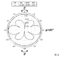
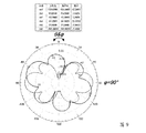
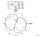
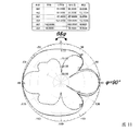
- the different types of beams comprise: single omnidirectional beam, single directional beam, directional double narrow beam, directional double wide beam, non-collinear directional dual beam, unequal width double beam, directional three beam and directional four beam At least one of them.
- the shaping algorithm of the single directional beam is an equal amplitude excitation of each omnidirectional sub-array unit, and the phase satisfies:
- i is an integer
- n 1, 2,3,...,N
- the elevation angle ⁇ m and azimuth of the maximum beam pointing respectively
- the present invention has the following advantages:
- the omnidirectional array antenna beamforming method of the invention adopts N array elements and array elements consisting of p-ary symmetric oscillator sub-arrays, and uniquely uses the following beamforming algorithm to realize different types of service beams, and more
- the realization of MIMO beamforming capability has high gain, multiple shaped beams, simple algorithm and low coupling of array elements.
- the omnidirectional array antenna will be 5G applications show great potential.
- the method has the characteristics of novel idea, clear principle, universal method, simple and easy to perform, and beamforming design for H, V single-polarized omnidirectional array antenna or H/V dual-polarized omnidirectional antenna. The offer is also valid and applicable.
- the different types of beams are equally in-phase excited to form an omnidirectional beam covering the horizontal periphery; 2) equal amplitude different phase excitation to form a horizontal directional beam, pointing to an azimuth;
- the equal amplitude excitation is performed to form a horizontal bidirectional narrow beam, the two beams are collinear and equal in width;
- the equal amplitude different phases are excited to form a horizontal bidirectional wide beam, and the two beams are collinear and equal in width;
- the different phases are excited to form a horizontal two-way unequal beam, the two beams are collinear and unequal in width; 6) the equal amplitude is excited by different phases to form a horizontal bidirectional narrow beam, and the two beams are equal in width and not collinear;
- the equal amplitude is excited by different phases to form a horizontally oriented three-beam, three beams with unequal wave widths and unequal angles; 8) equal amplitude and different phase excitations to form a horizontally
- the omnidirectional array antenna beamforming method of the invention adopts N array elements and array elements consisting of p-ary symmetric oscillator sub-arrays, and uniquely uses the following beamforming algorithm to realize different types of service beams, and more
- the realization of MIMO beamforming capability has high gain, multiple shaped beams, simple algorithm and low coupling of array elements.
- the omnidirectional array antenna will show great potential in 5G applications.
- the method has the characteristics of novel idea, clear principle, universal method, simple and easy to perform, and beamforming design for H, V single-polarized omnidirectional array antenna or H/V dual-polarized omnidirectional antenna. The offer is also valid and applicable.
- the different types of beams are equally in-phase excited to form an omnidirectional beam covering the horizontal periphery; 2) equal amplitude different phase excitation to form a horizontal directional beam, pointing to an azimuth;
- the equal amplitude excitation is performed to form a horizontal bidirectional narrow beam, the two beams are collinear and equal in width;
- the equal amplitude different phases are excited to form a horizontal bidirectional wide beam, and the two beams are collinear and equal in width;
- the different phases are excited to form a horizontal two-way unequal beam, the two beams are collinear and unequal in width; 6) the equal amplitude is excited by different phases to form a horizontal bidirectional narrow beam, and the two beams are equal in width and not collinear;
- the equal amplitude is excited by different phases to form a horizontally oriented three-beam, three beams with unequal wave widths and unequal angles; 8) equal amplitude different phase excitations to form a horizontally
- the present invention designs an eight-element beam-shaped omnidirectional antenna for future 5G applications, and eight sub-array units are evenly arranged on a circumference having a center wavelength (1 ⁇ c ).
- the array realizes azimuth-plane single omnidirectional beam, single directional beam, equal-width or unequal-width dual beam, collinear or non-collinear dual beam, triple beam and four beam coverage, which basically meets Beam requirements for multiple business models.
- This makes the omnidirectional shaped array which will become an extremely potential antenna solution for future 5G applications.
- the method has the characteristics of novel idea, clear principle, universal method, simple and easy to use, and is also applicable to the beamforming design of H, V single-polarized omnidirectional antenna or H/V dual-polarized omnidirectional antenna. Effective.
- FIG. 1 is a schematic diagram showing the definition of a Cartesian coordinate system used in the antenna model of the present invention.
- FIG. 2 is a front elevational view of an omnidirectional sub-array unit of an omnidirectional array antenna of the present invention.
- FIG. 3 is a top plan view of an omnidirectional array antenna model of the present invention.
- FIG. 4 is a front elevational view of the omnidirectional array antenna model of the present invention.
- FIG. 5 is a standing wave VSWR curve of the omnidirectional sub-array unit of the present invention.
- the present invention aims to provide a beam formable omnidirectional array antenna design for future 5G applications, and to shape the beam of H, V single-polarized omnidirectional array antenna or H/V dual-polarized omnidirectional antenna.
- the design provides an effective reference method.
- the method for constructing the omnidirectional array antenna of the present invention is as follows:
- Step one establish a spatial Cartesian coordinate system, as shown in Figure 1.
- Step 2 Construct an omnidirectional sub-array unit: in the YOZ plane, construct a ternary omnidirectional sub-array unit, including a dielectric plate 10, symmetric arms 21, 22, a center feed point 34, and a short-circuit point 35 at both ends, the center Feed point 34 provides pads and non-metallized vias, said shorting point 35 provides metallized vias, and printed parallel conductor feed lines 31, 32 and 33, each portion being as shown in FIG.
- a matrix array, and the circumference diameter is perpendicular to the PCB dielectric board 10 of each omnidirectional sub-array unit; each sub-array number is UC#1 ⁇ UC#8 (UC, Unit Cell, unit unit), respectively located in the azimuth 90°, 135°, 180°, 225°, 270°, 325°, and 360°, as shown in Figures 3 and 4.
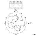
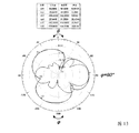
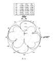
- Step 4 Array beamforming: using equal amplitude in-phase or different phase feeds to form eight Types of beams, as shown in Figures 7-14.
- the symmetric vibrator of the coaxial array in the omnidirectional sub-array unit is a half-wave oscillator, and may also include a half-wave vibrator or a vibrator of other wavelengths.
- the symmetric oscillators of the omnidirectional sub-array unit are coaxially arrayed into a vertically polarized sub-array or a coplanar array into a horizontally polarized sub-array.
- the symmetric vibrator of the omni-directional sub-array unit is printed on a PCB dielectric plate, and the dielectric plate is perpendicular to the diameter direction of the circular array.
- the symmetrical vibrator of the omnidirectional sub-array unit can also be constructed in the form of a metal tube.
- the different types of beams include: single omnidirectional beam #1, single directional beam #2, directional double narrow beam #3, directional double wide beam #4, and non-collinear Directional dual beam #5, directional unequal width dual beam #6, directional three beam #7 and directional four beam #8, a total of eight types of beams;
- the shaping algorithm of the single directional beam #2 is an equal-amplitude excitation of each omnidirectional sub-array unit, and the phase satisfies:
- the service beam 1) equal amplitude in-phase excitation, forming an omnidirectional beam covering the horizontal periphery; 2) equal amplitude different phase excitation, forming a horizontal directional beam, pointing to a certain azimuth; 3) equal amplitude different phase excitation, forming a horizontal bidirectional narrow beam, two waves
- the beam is collinear and equal in width; 4) the equal amplitude is excited by different phases to form a horizontal bidirectional wide beam, the two beams are collinear and equal in width; 5) the equal amplitude different phases are excited to form a horizontal bidirectional unequal width beam, two Beam collinear, unequal wave width; 6) equal amplitude different phase excitation, forming a horizontal bidirectional narrow beam, two beams equal wave width, not
- FIG. 5 is a standing wave VSWR curve of the omnidirectional sub-array unit of the present invention. It can be seen from the figure that in the 3.4 to 3.6 GHz band, the sub-array unit standing wave VSWR ⁇ 1.60, and the impedance matching is good.
- the H-plane is ideal omnidirectional radiation ( The out-of-roundness is less than 0.24 dB), and the gain G is 6.68 dBi.
- the gain G 6.47dBi
- the radiation characteristics are almost the same as the sub-array unit.
- the sidelobe level SLL is lower than the main lobe by about 7 dB and 5.5 dB, respectively, and forms a deep zero point with the main beam orthogonal direction and the intersection of the side side lobe and the main lobe.
Landscapes
- Engineering & Computer Science (AREA)
- Computer Networks & Wireless Communication (AREA)
- Signal Processing (AREA)
- Variable-Direction Aerials And Aerial Arrays (AREA)
Abstract
Dans la présente invention, une antenne réseau omnidirectionnelle comprend N unités de sous-réseau omnidirectionnelles qui sont agencées de manière circonférentielle afin de former un réseau circulaire, chacune des unités de sous-réseau omnidirectionnelles comprenant p oscillateurs symétriques disposés en réseau de manière coaxiale, et N et p étant tous les deux des nombres naturels. Selon le procédé de formation de faisceau d'antenne réseau omnidirectionnelle de la présente invention, diverses unités de sous-réseau omnidirectionnelles sont stimulées au moyen d'une équiamplitude, stimulation en phase ou hors phase, formant ainsi différents types de faisceaux de transaction, tels qu'un faisceau omnidirectionnel, un double faisceau, un triple faisceau et un quadruple faisceau. Selon la présente invention, diverses capacités de formation de faisceau MIMO d'une antenne omnidirectionnelle sont réalisées, ce qui permet d'obtenir un gain élevé, de multiples faisceaux formés, un algorithme simple, un couplage d'éléments de réseau faible et de faibles coûts ; en outre, l'antenne réseau omnidirectionnelle présente un immense potentiel dans des applications 5G futures. De plus, le procédé présente également les caractéristiques d'une nouvelle manière de penser, d'un principe transparent, d'une universalité de procédé, d'une simplicité et d'une facilité de mise en oeuvre, etc., et est également efficace et applicable à la fourniture d'une conception de formation de faisceau pour une antenne réseau omnidirectionnelle à polarisation unique H/V ou une antenne omnidirectionnelle à double polarisation H/V.
Priority Applications (3)
| Application Number | Priority Date | Filing Date | Title |
|---|---|---|---|
| PCT/CN2017/113091 WO2019100376A1 (fr) | 2017-11-27 | 2017-11-27 | Antenne réseau omnidirectionnelle et son procédé de formation de faisceau |
| US16/651,505 US11233335B2 (en) | 2017-11-27 | 2017-11-27 | Omnidirectional array antenna and beamforming method therefor |
| EP17932945.3A EP3720008A4 (fr) | 2017-11-27 | 2017-11-27 | Antenne réseau omnidirectionnelle et son procédé de formation de faisceau |
Applications Claiming Priority (1)
| Application Number | Priority Date | Filing Date | Title |
|---|---|---|---|
| PCT/CN2017/113091 WO2019100376A1 (fr) | 2017-11-27 | 2017-11-27 | Antenne réseau omnidirectionnelle et son procédé de formation de faisceau |
Publications (1)
| Publication Number | Publication Date |
|---|---|
| WO2019100376A1 true WO2019100376A1 (fr) | 2019-05-31 |
Family
ID=66630879
Family Applications (1)
| Application Number | Title | Priority Date | Filing Date |
|---|---|---|---|
| PCT/CN2017/113091 Ceased WO2019100376A1 (fr) | 2017-11-27 | 2017-11-27 | Antenne réseau omnidirectionnelle et son procédé de formation de faisceau |
Country Status (3)
| Country | Link |
|---|---|
| US (1) | US11233335B2 (fr) |
| EP (1) | EP3720008A4 (fr) |
| WO (1) | WO2019100376A1 (fr) |
Cited By (2)
| Publication number | Priority date | Publication date | Assignee | Title |
|---|---|---|---|---|
| CN111988075A (zh) * | 2020-07-10 | 2020-11-24 | 中国人民解放军战略支援部队航天工程大学 | 一种基于最大相关信噪比准则的天线组阵信号合成方法 |
| CN112054829A (zh) * | 2020-07-10 | 2020-12-08 | 中国人民解放军战略支援部队航天工程大学 | 一种具有固定相位中心特性的天线组阵信号合成方法 |
Families Citing this family (4)
| Publication number | Priority date | Publication date | Assignee | Title |
|---|---|---|---|---|
| GB201803433D0 (en) * | 2018-03-02 | 2018-04-18 | Secr Defence | Dual polarised antenna |
| EP4367751A4 (fr) * | 2021-07-06 | 2025-06-25 | John Mezzalingua Associates, LLC | Antenne quasi omnidirectionnelle 8t8r |
| CN118394108B (zh) * | 2024-06-25 | 2024-09-10 | 青岛蟒龙防务科技有限公司 | 一种基于实时数据分析的分布式无人机行进环境预警系统 |
| CN118763434B (zh) * | 2024-09-02 | 2025-01-24 | 中国科学院空天信息创新研究院 | 一种短波混合极化接收天线阵列 |
Citations (5)
| Publication number | Priority date | Publication date | Assignee | Title |
|---|---|---|---|---|
| CN2293901Y (zh) * | 1997-03-13 | 1998-10-07 | 北京信威通信技术有限公司 | 用于无线通信系统的环形智能天线阵 |
| US20100066590A1 (en) * | 2008-07-28 | 2010-03-18 | Physical Domains, LLC | Omnidirectional Retrodirective Antennas |
| CN107275800A (zh) * | 2017-05-16 | 2017-10-20 | 南京航空航天大学 | 一种大规模mimo阵列的天线结构 |
| CN107863996A (zh) * | 2017-11-27 | 2018-03-30 | 广东通宇通讯股份有限公司 | 全向阵列天线及其波束赋形方法 |
| CN207475549U (zh) * | 2017-11-27 | 2018-06-08 | 广东通宇通讯股份有限公司 | 全向阵列天线 |
Family Cites Families (9)
| Publication number | Priority date | Publication date | Assignee | Title |
|---|---|---|---|---|
| US4973971A (en) * | 1989-12-18 | 1990-11-27 | Allied-Signal Inc. | Broadband circular phased array antenna |
| GB2376567B (en) * | 2001-06-12 | 2005-07-20 | Mobisphere Ltd | Improvements in or relating to smart antenna arrays |
| GB2376568B (en) * | 2001-06-12 | 2005-06-01 | Mobisphere Ltd | Improvements in or relating to smart antenna arrays |
| US20130321207A1 (en) * | 2012-05-31 | 2013-12-05 | Alcatel-Lucent Usa Inc. | Transforming precoded signals for wireless communication |
| JP2014143591A (ja) * | 2013-01-24 | 2014-08-07 | Nippon Dengyo Kosaku Co Ltd | アレイアンテナ |
| US9729213B2 (en) * | 2014-01-30 | 2017-08-08 | Xirrus, Inc. | MIMO antenna system |
| WO2016126908A1 (fr) * | 2015-02-04 | 2016-08-11 | Artsys360 Ltd. | Système radar multimodal |
| CN106450703A (zh) * | 2016-11-24 | 2017-02-22 | 中国科学院国家空间科学中心 | 一种基于循环子阵的干涉式微波辐射计圆环天线阵列 |
| US10505609B2 (en) * | 2017-06-14 | 2019-12-10 | Commscope Technologies Llc | Small cell beam-forming antennas |
-
2017
- 2017-11-27 US US16/651,505 patent/US11233335B2/en active Active
- 2017-11-27 WO PCT/CN2017/113091 patent/WO2019100376A1/fr not_active Ceased
- 2017-11-27 EP EP17932945.3A patent/EP3720008A4/fr active Pending
Patent Citations (5)
| Publication number | Priority date | Publication date | Assignee | Title |
|---|---|---|---|---|
| CN2293901Y (zh) * | 1997-03-13 | 1998-10-07 | 北京信威通信技术有限公司 | 用于无线通信系统的环形智能天线阵 |
| US20100066590A1 (en) * | 2008-07-28 | 2010-03-18 | Physical Domains, LLC | Omnidirectional Retrodirective Antennas |
| CN107275800A (zh) * | 2017-05-16 | 2017-10-20 | 南京航空航天大学 | 一种大规模mimo阵列的天线结构 |
| CN107863996A (zh) * | 2017-11-27 | 2018-03-30 | 广东通宇通讯股份有限公司 | 全向阵列天线及其波束赋形方法 |
| CN207475549U (zh) * | 2017-11-27 | 2018-06-08 | 广东通宇通讯股份有限公司 | 全向阵列天线 |
Cited By (3)
| Publication number | Priority date | Publication date | Assignee | Title |
|---|---|---|---|---|
| CN111988075A (zh) * | 2020-07-10 | 2020-11-24 | 中国人民解放军战略支援部队航天工程大学 | 一种基于最大相关信噪比准则的天线组阵信号合成方法 |
| CN112054829A (zh) * | 2020-07-10 | 2020-12-08 | 中国人民解放军战略支援部队航天工程大学 | 一种具有固定相位中心特性的天线组阵信号合成方法 |
| CN111988075B (zh) * | 2020-07-10 | 2021-05-28 | 中国人民解放军战略支援部队航天工程大学 | 一种基于最大相关信噪比准则的天线组阵信号合成方法 |
Also Published As
| Publication number | Publication date |
|---|---|
| US11233335B2 (en) | 2022-01-25 |
| US20200303831A1 (en) | 2020-09-24 |
| EP3720008A1 (fr) | 2020-10-07 |
| EP3720008A4 (fr) | 2021-07-07 |
Similar Documents
| Publication | Publication Date | Title |
|---|---|---|
| CN107863996B (zh) | 全向阵列天线及其波束赋形方法 | |
| CN109687116B (zh) | C波段的小型化宽带宽波束圆极化微带天线 | |
| Tang et al. | Pattern-reconfigurable, flexible, wideband, directive, electrically small near-field resonant parasitic antenna | |
| WO2019100376A1 (fr) | Antenne réseau omnidirectionnelle et son procédé de formation de faisceau | |
| CN106450714A (zh) | 一种适用于阵列的宽带圆极化天线 | |
| CA2511684A1 (fr) | Antenne avec elimination du zero de rayonnement, antenne omnidirective et equipement de radiocommunication | |
| US20130241794A1 (en) | Microstrip antenna | |
| US20160006132A1 (en) | Dual-feed dual-polarization high directivity array antenna system | |
| CN105048079B (zh) | 一种全向性圆极化平面天线 | |
| CN107134648A (zh) | 一种l波段宽带双极化电磁偶极子天线 | |
| CN207475549U (zh) | 全向阵列天线 | |
| CN104505578A (zh) | 一种全向双圆极化天线 | |
| CN105811098A (zh) | 一种宽频带圆极化高增益天线 | |
| CN110635230A (zh) | 基于sicl谐振腔圆环缝隙和印刷振子的非对称双极化天线装置 | |
| CN105703084B (zh) | 一种室分天线 | |
| CN113782988A (zh) | 用于产生多模态oam波束的紧凑型顺序旋转同心均匀圆阵列 | |
| CN103107420A (zh) | 一种小型超宽带对称环-振子组合天线 | |
| CN105703062A (zh) | 一种宽频带高增益双极化5g基站阵列天线及其辐射单元 | |
| CN115207613B (zh) | 一种宽带双极化天线单元及天线阵列 | |
| CN107611601A (zh) | 小型化高增益双极化全向天线 | |
| CN107732441B (zh) | 波束上仰高增益全向天线 | |
| CN206850028U (zh) | 宽带高增益垂直极化全向天线 | |
| CN115642407B (zh) | 一种混合结构的圆极化扫描天线 | |
| CN116231300B (zh) | 1bit宽带辐射式可重构单元及波束扫描阵列天线 | |
| CN111478037A (zh) | 一种s波段小型化超宽带全向辐射垂直极化天线 |
Legal Events
| Date | Code | Title | Description |
|---|---|---|---|
| 121 | Ep: the epo has been informed by wipo that ep was designated in this application |
Ref document number: 17932945 Country of ref document: EP Kind code of ref document: A1 |
|
| NENP | Non-entry into the national phase |
Ref country code: DE |
|
| ENP | Entry into the national phase |
Ref document number: 2017932945 Country of ref document: EP Effective date: 20200629 |