WO2019102706A1 - Système de réseau optique passif, unité de réseau optique, terminal de ligne optique, procédé d'enregistrement d'unité de réseau optique et structure de données - Google Patents
Système de réseau optique passif, unité de réseau optique, terminal de ligne optique, procédé d'enregistrement d'unité de réseau optique et structure de données Download PDFInfo
- Publication number
- WO2019102706A1 WO2019102706A1 PCT/JP2018/035434 JP2018035434W WO2019102706A1 WO 2019102706 A1 WO2019102706 A1 WO 2019102706A1 JP 2018035434 W JP2018035434 W JP 2018035434W WO 2019102706 A1 WO2019102706 A1 WO 2019102706A1
- Authority
- WO
- WIPO (PCT)
- Prior art keywords
- reception level
- onu
- home
- olt
- station
- Prior art date
- Legal status (The legal status is an assumption and is not a legal conclusion. Google has not performed a legal analysis and makes no representation as to the accuracy of the status listed.)
- Ceased
Links
Images


Classifications
-
- H—ELECTRICITY
- H04—ELECTRIC COMMUNICATION TECHNIQUE
- H04B—TRANSMISSION
- H04B10/00—Transmission systems employing electromagnetic waves other than radio-waves, e.g. infrared, visible or ultraviolet light, or employing corpuscular radiation, e.g. quantum communication
- H04B10/60—Receivers
- H04B10/66—Non-coherent receivers, e.g. using direct detection
- H04B10/67—Optical arrangements in the receiver
-
- H—ELECTRICITY
- H04—ELECTRIC COMMUNICATION TECHNIQUE
- H04Q—SELECTING
- H04Q11/00—Selecting arrangements for multiplex systems
- H04Q11/0001—Selecting arrangements for multiplex systems using optical switching
- H04Q11/0062—Network aspects
- H04Q11/0067—Provisions for optical access or distribution networks, e.g. Gigabit Ethernet Passive Optical Network (GE-PON), ATM-based Passive Optical Network (A-PON), PON-Ring
-
- H—ELECTRICITY
- H04—ELECTRIC COMMUNICATION TECHNIQUE
- H04B—TRANSMISSION
- H04B10/00—Transmission systems employing electromagnetic waves other than radio-waves, e.g. infrared, visible or ultraviolet light, or employing corpuscular radiation, e.g. quantum communication
- H04B10/27—Arrangements for networking
- H04B10/272—Star-type networks or tree-type networks
-
- H—ELECTRICITY
- H04—ELECTRIC COMMUNICATION TECHNIQUE
- H04L—TRANSMISSION OF DIGITAL INFORMATION, e.g. TELEGRAPHIC COMMUNICATION
- H04L12/00—Data switching networks
- H04L12/28—Data switching networks characterised by path configuration, e.g. LAN [Local Area Networks] or WAN [Wide Area Networks]
- H04L12/44—Star or tree networks
-
- H—ELECTRICITY
- H04—ELECTRIC COMMUNICATION TECHNIQUE
- H04Q—SELECTING
- H04Q11/00—Selecting arrangements for multiplex systems
- H04Q11/0001—Selecting arrangements for multiplex systems using optical switching
- H04Q11/0062—Network aspects
- H04Q2011/0064—Arbitration, scheduling or medium access control aspects
Definitions
- the present invention relates to a PON system, a home-side device, a station-side device, a method of registering a home-side device, and a data structure.
- a passive optical network is a system that performs point-to-multipoint optical communication between an optical line terminal (OLT) and one or more optical network units (ONUs).
- An optical line termination device is a unit generally located at the service provider's premises, also referred to as a "station-side device.”
- An optical network unit (ONU) is a unit located at or near a subscriber's premises, and is also referred to as a "home-side device”.
- the OLT reception circuit detects the level of the received signal and performs gain control based on the detected level.
- Patent Document 1 discloses a bias control circuit that controls a DC voltage applied to an avalanche photodiode (APD).
- the bias control circuit detects the photocurrent generated by the APD and controls the voltage source according to the detected current.
- Patent Document 2 discloses a configuration for setting a bias voltage of an APD.
- the parent station (OLT) measures the reception level of the upstream optical signal in advance for each slave station (ONU), and stores the reception level.
- the master station sets the bias voltage of the APD based on the stored reception strength immediately before receiving the upstream optical signal from the specific slave station.
- Patent Document 3 Japanese Patent Application Laid-Open Nos. 2016-9897 (Patent Document 3) and Japanese Patent Application Laid-Open No. 2016-15640 (Patent Document 4) propose configurations for gain control of an optical amplifier.
- the burst signal is branched into signal light and monitor light by the optical coupler, and the level of the monitor light is detected.
- An optical fiber for delaying is introduced into the transmission path of the signal light.
- the gain of the optical amplifier can be controlled in accordance with the reception timing of the signal light.
- 100 Gbps class PON for example, 100 G-EPON
- the same fiber line as 10 G-EPON is used, and four different wavelength mutually having transmission capacity of 25.78 125 Gb / s (hereinafter referred to as “25 Gbps”)
- the transmission loss of the fiber line is a minimum of 15 dB / a maximum of 29 dB.
- Transmission speed is about 2.5 times faster for 100G-EPON than for 10G-EPON.
- the OLT is required to have an optical receiver having a wide band.
- the reception sensitivity of the OLT-side receiver is degraded by about 4 to 5 dB as compared with 10G-EPON.
- the increase in transmission rate causes deterioration in waveform quality of the transmission signal and an increase in penalty due to fiber chromatic dispersion.
- an optical multiplexer / demultiplexer is used to multiplex / demultiplex four waves. For this reason, it is necessary to consider the insertion loss (about 1.5 dB or so) of each of the optical multiplexer and the optical demultiplexer when receiving an optical signal in the station side apparatus.
- An OLT may receive a relatively strong optical signal from one ONU and may receive a relatively weak optical signal from another ONU.
- Patent Document 5 discloses a PON system capable of solving such a problem. In this PON system, communication is performed at a plurality of transmission rates. A terminal device not registered in the PON system sends a discovery response at one transmission rate within the discovery period.
- a PON system includes a station-side device, at least one home-side device, and an optical fiber connecting the station-side device and the home-side device, and is sent from the station-side device through the optical fiber.
- the reception level classification for dividing the reception level of the optical signal in the home apparatus is set, and the station apparatus corresponds to the reception level classification in the discovery process for searching for and registering an unregistered home apparatus. It is configured to register a home-side device.
- a PON system includes a station-side device, at least one home-side device, and an optical fiber that connects the station-side device and the home-side device.
- the station-side device includes an amplifier configured to amplify the optical signal received from the home-side device with variable gain, and is configured to determine and register the division of gain in the discovery process.
- the station-side apparatus sets the gain sections of the amplifier's gain in order from the lowest gain.
- An unregistered home device tries to respond to the discovery process in order from the lowest gain of the amplifier.
- the station-side device sets a gain classification for the unregistered home-side device.
- a home-side apparatus includes: a receiver configured to receive an optical signal; and a registration unit configured to register a reception level classification related to the reception level of the optical signal in the receiver; When the reception level classification specified in the discovery process for searching for and registering an unregistered home-side device falls under the reception level registered in the registration unit, a response to the discovery process is transmitted in the form of an optical signal And a transmitter configured.
- a station-side apparatus includes a receiver configured to receive an optical signal, and an amplifier provided upstream of the receiver and configured to amplify the optical signal with variable gain. And a transmitter configured to transmit an optical signal for discovery processing for searching for and registering an unregistered home apparatus, and the discovery process for comparison with the reception level classification of the home apparatus And a registration unit configured to register a home-side device that has specified the reception level division associated with the gain of the amplifier and responds to the discovery process.
- a method of registering a home device is a method of registering a home device in a PON system in which a station device and at least one home device are connected by an optical fiber. Setting the reception level division in the home apparatus for dividing the reception level in the home apparatus of the optical signal sent through the fiber, the station apparatus specifying the reception level, and registering the unregistered home side A step of executing a discovery process for searching for and registering a device, and an unregistered home-side device when the reception level designated by the station-side device corresponds to the reception level classification set in the unregistered home-side device And the station-side device register the home-side device that has responded to the discovery process.
- the data structure according to an aspect of the present invention is a data structure used for a discovery process in a PON system that causes a station-side device to recognize an unregistered home-side device, and the discovery process is specified by the station-side device
- the station-side device searches for the home-side device having the reception level segment, and the data structure includes the reception level segment for the notification from the station-side device to the home-side device.
- FIG. 1 is a view showing a configuration example of an optical communication system according to a first embodiment.
- FIG. 2 is a diagram for explaining the relationship between ONU reception level division and OLT reception level division according to the first embodiment.
- FIG. 3 is a sequence diagram for explaining an example of processing at the time of activating the ONU according to the first embodiment.
- FIG. 4 is a sequence diagram for explaining an example of a discovery process according to the first embodiment.
- FIG. 5 is a sequence diagram for explaining an example of the normal processing according to the first embodiment.
- FIG. 6 is a diagram schematically showing a part of a discovery gate message data structure according to the first mode.
- FIG. 7 is a diagram showing an example of the configuration of the optical communication system according to the second embodiment.
- FIG. 1 is a view showing a configuration example of an optical communication system according to a first embodiment.
- FIG. 2 is a diagram for explaining the relationship between ONU reception level division and OLT reception level division according to the first embodiment.
- FIG. 3 is
- FIG. 8 is a sequence diagram for explaining an example of processing at the time of activating the ONU according to the second embodiment.
- FIG. 9 is a sequence diagram for explaining an example of discovery processing (failure in registration of ONU) according to the second embodiment.
- FIG. 10 is a sequence diagram for explaining an example of the discovery process (the registration of the ONU is successful) according to the second embodiment.
- FIG. 11 is a diagram schematically showing an example of mapping information applicable to the third embodiment.
- FIG. 12 is a diagram schematically showing a part of the data structure of a discovery gate message according to the third mode.
- FIG. 13 is a first sequence diagram illustrating an example of a discovery process according to the third embodiment.
- FIG. 14 is a second sequence diagram for explaining a process following the process shown in FIG. FIG.
- FIG. 15 is a first sequence diagram for explaining another example of the discovery process according to the third embodiment.
- FIG. 16 is a second sequence diagram for explaining the process following the process shown in FIG.
- FIG. 17 is a diagram showing another example of the mapping information according to the third embodiment.
- FIG. 18 is a diagram showing an example of the configuration of an optical communication system according to a fourth embodiment.
- FIG. 19 is a diagram showing a configuration example of measuring transmission power of an ONU according to the fourth embodiment.
- FIG. 20 is a sequence diagram for explaining an example of processing at the time of activating the ONU according to the fourth embodiment.
- FIG. 21 is a sequence diagram for explaining an example of a discovery process according to the fourth embodiment.
- FIG. 22 is a diagram showing setting of reception level classification of ONU according to the fifth embodiment.
- FIG. 23 is a schematic diagram showing an example of a discovery message according to the fifth embodiment.
- FIG. 24 is a sequence diagram for explaining an example of processing at the time of activation of an ONU according to the fifth embodiment.
- FIG. 25 is a sequence diagram for explaining an example of a discovery process according to the fifth embodiment.
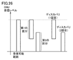
- FIG. 26 is a diagram showing setting of reception level division of ONU according to the sixth embodiment.
- FIG. 27 is a schematic diagram for explaining a discovery process according to the sixth embodiment.
- FIG. 28 is a diagram for explaining the determination of the reception level division of the ONU by the OLT.
- FIG. 29 is a diagram showing the relationship between the discovery process and the gain of the SOA.
- FIG. 30 is a sequence diagram for explaining an example of a discovery process according to the seventh embodiment.
- FIG. 30 is a sequence diagram for explaining an example of a discovery process according to the seventh embodiment.
- FIG. 31 is a sequence diagram for explaining an example of a discovery process according to the eighth embodiment.
- FIG. 32 is a sequence diagram for explaining another example of the discovery process according to the eighth embodiment.
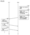
- FIG. 33 is a sequence diagram for explaining another example of the process in communication according to the ninth embodiment.
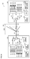
- FIG. 34 is a diagram showing an example of configuration of an optical communication system according to the tenth embodiment.
- the OLT Before registering an ONU, the OLT can not have information on the reception level of that ONU. Thus, the OLT can not guarantee gain control in receiving the optical signal from its ONU. None of the documents mentioned above propose a solution to such a problem.
- An object of the present disclosure is to provide an apparatus and method for enabling to register an ONU while guaranteeing gain control in reception of an optical signal from an unregistered ONU. [Effect of the present disclosure] According to the present disclosure, it is possible to register an ONU while guaranteeing gain control in reception of an optical signal from an unregistered ONU.
- a PON system includes a station-side device, at least one home-side device, and an optical fiber connecting the station-side device and the home-side device, and the station-side device Reception level classification is set in order to classify the reception level of the optical signal sent through the home device in the home device, and in the discovery process in which the station device searches for and registers an unregistered home device, the reception level classification Are configured to register the corresponding home-side device.
- the length of the optical fiber connecting the station-side device and the home-side device can be different for each home-side device. Because the length of the optical fiber may differ depending on the distance from the station apparatus to the home apparatus due to the transmission loss of the optical fiber, the reception level of the optical signal from each home apparatus is the station side apparatus. It can be different.
- the station-side device is configured to set the reception level classification and to register the home-side device corresponding to the reception level. During the discovery process, a signal having an appropriate intensity is input from the home device to the station device. Therefore, while guaranteeing gain control in reception of an optical signal from an unregistered home apparatus, the home apparatus can be registered by discovery processing.
- the station-side apparatus is configured to specify the reception level division in the discovery process.
- the unregistered home-side apparatus determines the reception level classification based on the reception level, and responds to the station-side apparatus when the reception level designated by the station-side apparatus falls under the determined reception level classification. Configured as.
- the station-side apparatus includes an amplifier configured to amplify an optical signal received from the home-side apparatus with variable gain, and is configured to specify a reception level division in a discovery process.
- the receive level segment is associated with the gain of the amplifier.
- the unregistered home-side apparatus tries the response to the discovery process in order from the lower gain of the amplifier, and the reception level classification specified in the discovery process for which the response is successful is taken as the reception level classification of the unregistered home-side apparatus.
- the station-side device determines the reception level division.
- the station apparatus includes an amplifier configured to amplify an optical signal received from the home apparatus with variable gain.
- the reception level segments are associated with one or more gain level segments of gain.
- the station-side device is configured to transmit the reception level division determined by the station-side device to the home-side device.
- the reception level division can be set optimally according to the characteristics of the amplifier of the station side apparatus. For example, gain control can be realized in consideration of individual differences in amplifier characteristics.
- the station-side device is configured to determine whether or not the unregistered home-side device can be registered when the unregistered home-side device responds to the discovery process.
- the station-side device can more accurately determine whether the home-side device should be registered.
- the determination by the station apparatus includes comparing the correction frequency in the error correction process with a threshold.
- the station-side device can determine whether to register the home-side device based on the correction frequency in the error correction process.
- the reception level division is set based on the reception power of the home apparatus.
- the station-side device can directly grasp the reception level of the home-side device from the reception power of the home-side device.
- the reception level division is set based on the line loss of the optical fiber corresponding to the difference between the transmission power of the station apparatus and the reception power of the home apparatus.
- the station-side device can estimate the reception level of the home-side device from the line loss of the optical fiber.
- the reception level division is set by the maximum value of the reception level of the home apparatus and the minimum value of the reception level of the home apparatus.
- the reception level division can be set by the range of reception levels. (11)
- the station-side device executes the discovery process, the station-side device includes the maximum value and the minimum value in the discovery gate message.
- the station-side device can notify the home-side device of the reception level division by the discovery gate message.
- At least one of the maximum value and the minimum value is a variable value.
- the range of reception levels for one reception level division can be set arbitrarily.
- the station-side device changes the reception level division from the first division to a second division having a range overlapping with a part of the first division.
- the home apparatus receives the higher one of the first and second divisions.
- the level division is set, it responds to the station apparatus.
- the home-side device measures the reception level of the home-side device, and determines whether the reception level corresponds to the reception level classification based on the measurement value of the reception level.
- the station-side device can register the home-side device corresponding to the reception level classification.
- the reception level division is set based on the line loss of the optical fiber corresponding to the difference between the transmission power of the station apparatus and the reception power of the home apparatus.
- the station-side device can register the home-side device corresponding to the reception level classification.
- the station apparatus sets a set of maximum value and minimum value multiple times.
- the plurality of sets includes a first set and a second set that satisfy the relation that the maximum value of the second set is larger than the minimum value of the first set.
- the station-side apparatus executes discovery processing in order from the highest one of the plurality of sets.
- a PON system includes a station-side device, at least one home-side device, and an optical fiber connecting the station-side device and the home-side device.
- the station-side device includes an amplifier configured to amplify the optical signal received from the home-side device with variable gain, and is configured to determine and register the division of gain in the discovery process.
- the station-side apparatus sets the gain sections of the amplifier's gain in order from the lowest gain.
- the unregistered home-side device tries to respond to the discovery process in order from the lowest gain of the amplifier.
- the station-side device sets a gain classification for the unregistered home-side device.
- the unregistered home apparatus tries to respond to the discovery process in order from the lower gain of the amplifier.
- the station apparatus can amplify the optical signal with low gain.
- the station-side device can receive an optical signal having an appropriate intensity.
- the home device can be registered by the discovery process while guaranteeing gain control in receiving an optical signal from an unregistered home device.
- the station-side device repeatedly performs setting of the gain of the amplifier, and sets the gain division for the home-side device whose response is confirmed with a gain lower than the registered gain division.
- the station-side device includes an optical receiver that receives the optical signal amplified by the amplifier.
- the local apparatus selects a gain section having the smallest gain, and resets the gain sections in order from the lowest gain.
- the home apparatus monitors the reception level of the home apparatus, and stops the light output when the reception level exceeds the threshold.
- the station-side device determines that the home-side device is abnormal by stopping the light output from the home-side device, releases the logical link of the home-side device to the PON system, and performs the discovery process. Register the device again.
- the station apparatus includes an optical receiver that receives an optical signal from the home apparatus and changes the multiplication factor according to the applied voltage.
- the station-side device changes the voltage applied to the optical receiver according to the reception level division.
- the station-side apparatus can change the amplification factor of the optical signal.
- a home-side apparatus is a receiver configured to receive an optical signal, and a registration configured to register a reception level classification related to the reception level of the optical signal at the receiver. Sends a response to the discovery process in the form of an optical signal when the reception level classification specified in the discovery process for searching and registering an unregistered home-side device corresponds to the reception level registered in the registration unit. And a transmitter configured to:
- the home-side device when the reception level classification of its own corresponds to the reception level classification specified in the discovery processing, the home-side device responds to the discovery processing. Therefore, management of the home apparatus based on the reception level classification can be realized.
- a station-side apparatus includes a receiver configured to receive an optical signal, and a receiver provided at a front stage of the receiver, configured to amplify the optical signal with variable gain. And a transmitter configured to transmit an optical signal for a discovery process to search for and register an unregistered home device, and for matching with the reception level classification of the home device.
- the method further includes a registration unit that is configured to register a home-side device that is specified in the discovery process and that is associated with the reception level division associated with the gain of the amplifier and that responds to the discovery process.
- the station-side device registers the home-side device having the reception level classification corresponding to the designated reception level classification. Therefore, management of the home apparatus based on the reception level classification can be realized.
- a method of registering a home device is a method of registering a home device in a PON system in which a station device and at least one home device are connected by an optical fiber, Step of setting reception level division in the home apparatus for dividing reception level in the home apparatus of the optical signal sent from the apparatus through the optical fiber, and the station apparatus designates the reception level and is not registered Step of executing a discovery process for searching and registering a home-side device, and the reception level designated by the station-side device being unregistered if it corresponds to the reception level classification set in the unregistered home-side device
- the home-side device responds to the discovery process, and the station-side device registers the home-side device that responded to the discovery process. .
- the station-side device registers the home-side device having the reception level classification corresponding to the designated reception level classification. Therefore, management of the home apparatus based on the reception level classification can be realized.
- a data structure according to an aspect of the present invention is a data structure used for discovery processing in a PON system that causes an unregistered home apparatus to be recognized by a station apparatus, and the discovery process is performed by the station apparatus
- the station-side device searches for a home-side device having a designated reception level segment, and the data structure includes a reception level segment for notification from the station-side device to the home-side device.
- data can be acquired in the home apparatus for determining in the home apparatus whether the registered reception level classification corresponds to the designated reception level classification.
- PON is shown as an embodiment of the optical communication system. Unless otherwise limited, "PON” includes EPON (Ethernet (R) Passive Optical Network).
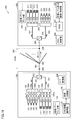
- FIG. 1 is a view showing a configuration example of an optical communication system according to a first embodiment.
- the PON system 300 includes an OLT (station-side device) 100, an ONU (home-side device) 200, and an optical distribution network 301.
- OLT station-side device
- ONU home-side device
- optical distribution network 301 optical distribution network
- the optical distribution network 301 is constituted by an optical fiber line and an optical splitter 302.
- the OLT 100 and the ONUs 200 are connected to the optical distribution network 301.
- An ODN (Optical Distribution Network) section 306 is a section of the optical distribution network 301 that includes the optical splitter 302 and is sandwiched by defining points 304 and 305.
- the optical splitter 302 splits the optical distribution network 301. Thereby, a plurality of ONUs can be connected to the optical distribution network 301. In FIG. 1, one ONU 200 is representatively shown.
- the PON system 300 realizes a 100 Gbps class PON (for example, 100 G-EPON).
- 100G-EPON the same fiber line as 10G-EPON is used to transmit four optical signals with different wavelengths, each having a transmission capacity of 25.78125 Gb / s (hereinafter referred to as "25 Gbps").
- Ru the same fiber line as 10G-EPON is used to transmit four optical signals with different wavelengths, each having a transmission capacity of 25.78125 Gb / s (hereinafter referred to as "25 Gbps").
- the OLT 100 includes an optical transmission path 101, an optical reception path 102, a diplexer filter 103, and semiconductor optical amplifiers (SOAs) 105a, 105b, 105c, 105d, 106a, 106b, 106c, and 106d. , An optical multiplexer 110, an optical demultiplexer 120, optical transmitters 111-114, and optical receivers 121-124.
- the OLT 100 can include a module (for example, an optical transceiver) that includes the above-described elements.
- FIG. 1 shows a configuration related to transmission and reception of an optical signal of the OLT 100.
- the light transmission path 101 and the light reception path 102 are configured by an optical waveguide, an optical fiber, and the like.
- the diplexer filter 103 is a component for optically separating the light transmission path 101 and the light reception path 102.
- Each of the optical transmitters 111 to 114 includes, for example, an electro-absorption modulator integrated laser diode (EML) as a light emitting element for generating an optical signal.
- EML electro-absorption modulator integrated laser diode
- the optical transmitters 111 to 114 emit light of different wavelengths.
- Each optical transmitter has a transmission capacity of 25 Gbps. Therefore, 25 Gbps ⁇ 4 channels are realized. There is no particular limitation on which one of the four channels each optical transmitter is assigned to.
- the SOAs 105a, 105b, 105c, and 105d amplify optical signals emitted from the optical transmitters 111 to 114, respectively.
- the optical multiplexer 110 multiplexes the four optical signals amplified by the SOAs 105 a, 105 b, 105 c, and 105 d by wavelength multiplexing.
- the optical transmission path 101 optically couples the optical multiplexer 110 and the SOAs 105 a, 105 b, 105 c, and 105 d to the optical transmitters 111 to 114.
- the optical signal from the optical multiplexer 110 is transmitted through the optical transmission path 101.
- the optical signal passes through the diplexer filter 103 and is sent out from the OLT 100 to the optical distribution network 301.
- the OLT 100 receives an optical signal from the ONU 200.
- This optical signal is a burst signal.
- the burst signal passes through the diplexer filter 103 and is routed to the optical receiving path 102.
- the optical signal from the ONU 200 is a wavelength division multiplexed (WDM) optical signal.
- the optical demultiplexer 120 separates the optical signal transmitted through the optical receiving path 102 into four optical signals based on the wavelength.
- the optical reception path 102 is optically coupled to the SOAs 106 a, 106 b, 106 c, and 106 d by being optically coupled to the optical demultiplexer 120.
- the SOAs 106a, 106b, 106c, and 106d are provided in front of the optical receivers 121 to 124, respectively, and amplify the optical signals input from the optical demultiplexer 120.
- Each of the light receivers 121 to 124 is a light receiver having high sensitivity, and includes, for example, an avalanche photodiode (APD) as a light receiving element.
- the optical receivers 121, 122, 123, 124 are respectively associated with four channels.
- the OLT 100 further includes an OLT control unit 130, an ONU information management unit 131, and a gain control unit 132.
- the OLT control unit 130 controls the operation of the OLT 100.
- the ONU information management unit 131 registers an ONU corresponding to the reception level classification designated by the OLT 100 in a discovery process of searching for and registering an unregistered ONU. Thereby, the ONU information management unit 131 manages information on the reception level of each ONU 200.
- An SOA is an amplifier with variable gain.
- the gain control unit 132 controls the gains of the SOAs 106 a, 106 b, 106 c, and 106 d based on the information (reception level of each ONU 200) managed by the ONU information management unit 131.
- the OLT control unit 130, the ONU information management unit 131, and the gain control unit 132 are realized by a single semiconductor circuit.
- the OLT control unit 130, the ONU information management unit 131, and the gain control unit 132 may be realized by individual semiconductor integrated circuits. Any two of the OLT control unit 130, the ONU information management unit 131, and the gain control unit 132 may be realized by one semiconductor integrated circuit.
- Such a semiconductor integrated circuit can be, for example, an application specific integrated circuit (ASIC), a field programmable gate array (FPGA), or the like.
- the OLT control unit 130, the ONU information management unit 131, and the gain control unit 132 are included in the OLT 100. However, at least one of the OLT control unit 130, the ONU information management unit 131, and the gain control unit 132 may be provided outside the OLT 100.
- the ONU 200 includes an optical transmission path 201, an optical reception path 202, a diplexer filter 203, an optical transmission path 204, an optical multiplexer 210, an optical demultiplexer 220, optical transmitters 211 to 214, and an optical receiver 221 to And an ONU control unit 240, a received signal strength indication (RSSI) circuit 241, and a reception level classification registration / holding unit 243.
- An ONU 200 can include a module (eg, an optical transceiver) that includes the elements described above.
- the modules of the ONU 200 may include optional elements of the components shown in FIG.
- the “selective elements” are, for example, the optical transmission path 201, the optical reception path 202, the diplexer filter 203, the optical multiplexer 210, the optical demultiplexer 220, the optical transmitters 211 to 214, and the optical receivers 221 to 224. It is also good.
- the above-mentioned "optional element” may include the same number of optical transmitters and optical receivers selected among the optical transmitters 211 to 214 and the optical receivers 221 to 224.
- the OLT 100 can similarly include the same number of optical transmitters and optical receivers selected from among the optical transmitters 111 to 114 and the optical receivers 121 to 124 as "selective elements”. .
- the light transmission path 201, the light reception path 202, and the light transmission path 204 are configured by an optical waveguide, an optical fiber, and the like.
- the diplexer filter 203 is a component for optically separating the light transmission path 201 and the light reception path 202.
- the optical transmission path 204 is a transmission path common to the optical transmission path 201 and the optical reception path 202.
- the optical multiplexer 210 is disposed in the optical transmission path 201.
- the optical demultiplexer 220 is disposed in the optical receiving path 202.
- Each of the light transmitters 211 to 214 can include an EML as a light emitting element.
- the light emitting element of each of the light transmitters 211-214 may be a Direct Modulation Laser Diode (DML).
- DML Direct Modulation Laser Diode
- the optical transmitters 211 to 214 emit optical signals of different wavelengths. This optical signal is a burst signal.
- Each optical transmitter has a transmission capacity of 25 Gbps. Therefore, 25 Gbps ⁇ 4 channels are realized. There is no particular limitation on which one of the four channels each optical transmitter is assigned to.
- the optical multiplexer 210 multiplexes the four optical signals respectively emitted from the optical transmitters 211 to 214 by wavelength multiplexing.
- the multiplexed optical signal is transmitted through the optical transmission path 201 and passes through the diplexer filter 203.
- the optical signal transmitted through the optical transmission path 201 is sent out to the optical distribution network 301 as an upstream optical signal from the ONU 200.
- the ONU 200 receives an optical signal from the OLT 100.
- the optical signal is transmitted through the optical transmission path 204 and routed to the optical reception path 202 by the diplexer filter 203.
- the optical demultiplexer 220 separates the optical signal transmitted through the optical receiving path 202 into four optical signals based on the wavelength.
- the four optical signals are input to the optical receivers 221 to 224, respectively.
- Each of the light receivers 221 to 224 is a light receiver having high sensitivity.
- Each of the light receivers 221 to 224 can include an avalanche photodiode as a light receiving element.
- the optical receivers 221, 222, 223 and 224 are respectively associated with four channels.
- the RSSI circuit 241 is a monitor circuit that monitors the reception level (received signal strength) of the ONU 200. In one embodiment, the RSSI circuit 241 monitors the reception level in any one of the four channels. The RSSI circuit 241 may monitor the maximum value or the minimum value of the reception levels of the four channels. Alternatively, the RSSI circuit 241 may monitor the average value of the reception levels of the four channels.
- the reception level classification registration / holding unit 243 is a registration unit for registering the reception level classification of the ONU 200.
- the reception level segment registration / holding unit 243 registers the reception level segment of the ONU 200 based on the output of the RSSI circuit 241 and holds the information of the reception level segment.
- the reception level of the ONU 200 is divided into, for example, “high”, “medium”, and “low”.
- the ONU control unit 240, the RSSI circuit 241, and the reception level division registration / holding unit 243 can be realized by one or more semiconductor integrated circuits.
- a semiconductor integrated circuit can be, for example, an application specific integrated circuit (ASIC), a field programmable gate array (FPGA), or the like.
- reception level divisions are set for dividing the reception level at the ONU 200 of the optical signal transmitted from the OLT 100 through the optical distribution network 301 (optical fiber).
- the OLT 100 is configured to register an ONU 200 corresponding to the reception level classification in a discovery process of searching for and registering an unregistered ONU.
- One ONU 200 is shown in FIG. 1 and the drawings described hereinafter. Although this ONU 200 is connected to the optical distribution network 301, it is assumed that it has not been registered in the OLT 100 yet.
- the OLT 100 transmits a message, which may also be called a discovery gate, in order to search for and register an unregistered ONU.
- the OLT 100 designates the reception level division at the discovery gate and transmits the designated discovery gate.
- the transmission of the discovery gate is also referred to below as "discovery notification”.
- the OLT 100 controls the gain of the receiving side SOA in association with the designated reception level division.
- the “receiving side SOA” is an SOA that amplifies an optical signal received at the OLT 100, and is at least one of the SOAs 106a to 106d.
- the gain control unit 132 reduces the gain of the receiving side SOA.
- the gain control unit 132 increases the gain of the reception side SOA.
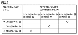
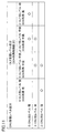
- FIG. 2 is a diagram for explaining the relationship between ONU reception level division and OLT reception level division according to the first embodiment.
- the ONU reception level is divided into three, for example, “weak”, “medium”, and “strong”.
- the number of reception level divisions may be two or more, and is not limited to three.
- the ONU reception level division and the OLT reception level division have a one-to-one relationship. Therefore, the OLT reception level is also divided into three, "weak", “medium” and “strong". Symbols indicated by circles in FIG. 2 indicate the correspondence between ONU reception level divisions and OLT reception level divisions.
- the optical signal in the ODN section 306 is attenuated more. Therefore, when the ONU reception level segment is "weak", the OLT reception level segment is "weak". On the other hand, when the ODN section 306 is short, the attenuation of the optical signal in the ODN section 306 is small. When the ONU reception level classification is "strong”, the OLT reception level classification is "strong".
- the OLT reception level and the gain control section of the receiving side SOA of the OLT are in an inverse relationship to each other.
- the OLT reception level segment is "weak”
- the OLT reception level segment is "weak”
- the gain control segment of the SOA is "strong”.
- the OLT reception level segment is "strong”
- the gain control segment of the SOA is "weak”.
- both the OLT reception level division and the gain control division of the SOA are "middle”.
- the relationship shown in FIG. 2 is held by the OLT 100 and the ONU 200 as a rule common to the OLT 100 and the ONU 200.
- specifications for each of the OLT 100 and the ONU 200 to operate according to the relationship shown in FIG. 2 may be predetermined.
- the controller (OLT control unit 130 and ONU control unit 240) of each of the OLT 100 and the ONU 200 may operate according to a program in which the relationship shown in FIG. 2 is defined, and even if information according to FIG. Good.
- the OLT 100 and the ONU 200 may receive the information according to FIG. 2 from an external device not shown.
- the ONU 200 may receive the information according to FIG. 2 from the OLT 100.
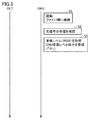
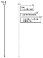
- FIG. 3 is a sequence diagram for explaining an example of processing at the time of activating the ONU according to the first embodiment.
- the ONU 200 is activated by powering on the ONU 200.
- the ONU 200 can be optically coupled to the optical fiber network (optical distribution network 301). That is, the ONU 200 is connected to the optical fiber network.
- the optical signal from the OLT 100 is distributed to a plurality of ONUs connected to the optical distribution network 301.
- the ONU 200 confirms the reception of the optical signal.
- the RSSI circuit 241 of the ONU 200 acquires a reception level (RSSI) based on the output of the optical receiver.
- the reception level segment registration / holding unit 243 registers and holds reception level segments according to the reception level.
- the reception level division is "medium".
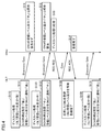
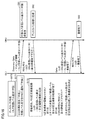
- FIG. 4 is a sequence diagram for explaining an example of a discovery process according to the first embodiment. As shown in FIG. 4, in step S110, a discovery process in which the OLT reception level classification is set to "strong" is executed.
- Step S110 includes step S111.
- the OLT 100 sets the gain of the receiving side SOA to “low”.
- the OLT 100 transmits a discovery gate (Discovery Gate) message to notify the OLT 100 of the reception level division ("strong").
- the reception level classification of the OLT 100 corresponds to the condition for registering an unregistered ONU.
- the ONU 200 receives a discovery gate message.
- the ONU 200 checks the reception level classification (notified reception level classification) included in the discovery gate message with the reception level classification registered in the ONU 200. Since the reception level segment registered in the ONU 200 is “middle”, the notified reception level segment does not correspond to the reception level segment registered in the ONU 200. Thus, the ONU 200 does not respond to the discovery gate message.
- Step S120 a discovery process in which the OLT reception level classification is set to "middle" is executed.
- Step S120 includes steps S121 and S122.
- step S121 the OLT 100 sets the gain of the receiving side SOA to "medium”.
- the OLT 100 transmits a discovery gate message to notify the reception level classification ("middle") of the OLT 100.
- step S12 the ONU 200 receives a discovery gate message.
- the ONU 200 collates the reception level classification included in the discovery gate message with the reception level classification registered in the ONU 200.
- the notified reception level classification corresponds to the reception level classification registered in the ONU 200.
- step S13 the ONU 200 responds to the discovery gate message.
- the ONU 200 transmits a registration request (REG_REQ) to the OLT 100.
- the OLT 100 registers the ONU (ONU 200) that has responded to the discovery message.
- the OLT 100 sends a registration (Register) message to the ONU 200 and notifies an LLID (Logical Link ID).
- the OLT 100 transmits a Gate message for notifying the ONU 200 of the transmission band and transmission timing.
- the ONU 200 transmits a reception response (REG_ACK) of the registration message (Register) to the OLT 100 (Step S14).
- the OLT 100 holds the reception level classification of the registered ONU.
- the ONU information management unit 131 holds information on the reception level classification of the ONU.
- Step S130 a discovery process in which the OLT reception level classification is set to "weak” is executed.
- Step S130 includes step S131.
- the OLT 100 sets the gain of the reception side SOA to "strong”.
- the OLT 100 transmits a discovery gate message to notify the OLT 100 of the reception level classification ("weak").
- the OLT 100 repeatedly executes the processes of steps S110, S120, and S130.
- the reception level classification registration / holding unit 243 determines whether the registered reception level classification corresponds to the reception level classification designated by the OLT 100.
- the ONU corresponding to the designated reception level division responds to the discovery notification from the OLT 100.
- the reception level segment registration / holding unit 243 gives transmission permission to at least one of the optical transmitters 211 to 214.
- the ONU 200 transmits a signal (registration request) in response to the discovery notification.
- the OLT 100 receives a registration request from the ONU 200.
- the ONU information management unit 131 registers the ONU 200 together with the reception level classification of the ONU 200.
- the OLT 100 registers an ONU corresponding to the reception level classification designated by the OLT 100.
- the OLT 100 can manage the reception level division of each of the plurality of registered ONUs.
- FIG. 5 is a sequence diagram for explaining an example of the normal processing according to the first embodiment.
- the OLT 100 receives a burst signal from the ONU 200.
- the OLT 100 designates to the ONU 200 the timing at which the ONU 200 transmits a burst signal by band allocation. Therefore, the OLT 100 knows the timing at which the ONU 200 transmits a burst signal.
- the OLT 100 acquires the reception level division of the ONU which will transmit a signal to be received by the OLT 100.
- step S202 the OLT 100 sets the gain of the receiving-side SOA corresponding to the ONU reception level division at the signal reception timing. As shown in FIG. 2, the ONU reception level division and the OLT reception level division are associated.
- the gain control unit 132 reads the information on the reception level classification of the ONU 200 from the ONU information management unit 131.
- the gain control unit 132 executes gain control of the receiving side SOA according to the timing of reception of the burst signal.
- step S20 the ONU 200 transmits a burst signal at the transmission timing designated by the OLT 100.
- step S203 the OLT 100 receives a burst signal.
- the receiving side SOA of the OLT 100 amplifies the burst signal with a gain corresponding to the OLT reception level division.
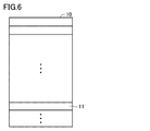
- FIG. 6 is a diagram schematically showing a part of a discovery gate message data structure according to the first mode.
- the discovery gate message 10 includes, as an item, an OLT reception level division 11 for notifying the reception level division set by the OLT 100 from the OLT 100 to an unregistered ONU.
- the position of the OLT reception level segment 11 in the discovery gate message 10 and the data length of the OLT reception level segment 11 are not limited.
- the OLT 100 can set the gain of the receiving side SOA prior to the reception of the burst signal. If the burst signal is strong, the OLT 100 can start receiving the burst signal with the gain of the receiving side SOA lowered. Thereby, it is possible to prevent strong light from entering the light receiver of the OLT 100. Therefore, the possibility of damaging the light receiving element included in the optical receiver can be reduced.
- the ONU can be registered by the discovery process while guaranteeing gain control in the reception of optical signals from unregistered ONUs.
- a high-speed level detection circuit In order to control the gain of the receiving side SOA after the burst signal strength is detected by the OLT, a high-speed level detection circuit is required. Alternatively, an optical element such as a branching element and an optical fiber for delaying signal light as shown in Patent Documents 3 and 4 is required. On the other hand, according to the first embodiment, it is possible to eliminate the need for a high-speed level detection circuit or an additional optical component. Therefore, cost reduction or miniaturization of the OLT 100 can be achieved. Furthermore, the problem of insertion loss due to the addition of optical components can also be avoided.
- FIG. 7 is a diagram showing an example of the configuration of the optical communication system according to the second embodiment. Compared with the first embodiment, the configuration of the ONU 200 is different in the second embodiment. As shown in FIG. 7, in the ONU 200, the RSSI circuit 241 is omitted. An SOA gain classification identifying unit 244 is provided in the ONU 200 in place of the reception level classification registration / holding unit 243.
- the SOA gain category identification unit 244 holds the history regarding the registration process.
- the SOA gain category identification unit 244 associates the reception level category of the ONU 200 with the result (success or failure) of responding to the discovery.
- the ONU 200 changes the ONU reception segment and tries registration processing.
- the reception level classification of the ONU 200 is “strong”, “medium”, “weak”.
- the relation between the ONU reception level division and the OLT reception level division according to the second embodiment can be made equal to the relation of the first embodiment (see FIG. 2).
- FIG. 8 is a sequence diagram for explaining an example of processing at the time of activating the ONU according to the second embodiment.
- the processes of steps S1 and S2 shown in FIG. 8 are the same as the corresponding processes shown in FIG.
- the ONU 200 performs initial setting of ONU reception level division.
- the initial setting of the reception division of the ONU 200 is “strong”.
- the SOA gain category identification unit 244 temporarily registers “strong” as the ONU reception level category.
- FIG. 9 is a sequence diagram for explaining an example of discovery processing (failure in registration of ONU) according to the second embodiment.
- step S110 a discovery process in which the OLT reception level classification is set to "strong” is executed.
- step S111 the OLT 100 sets the gain of the receiving side SOA to “low”.
- the OLT 100 transmits a discovery gate message to notify the OLT 100 of the reception level classification ("strong").
- step S31 the unregistered ONU (ONU 200) receives the discovery gate message and receives the reception level classification (notified reception level classification) included in the discovery gate message with the reception level classification temporarily registered in the ONU 200. Match. Since the reception level segment registered in the ONU 200 is “strong”, the notified reception level segment corresponds to the registered reception level segment.
- step S32 the ONU 200 transmits a registration request (REG_REQ) to the OLT 100 in response to the discovery gate message.
- the OLT 100 receives the response from the ONU 200 in step S112. If the actual reception level is "medium”, the actual reception level does not match the ONU's reception level division ("high"). In this case, the OLT 100 can not receive the optical signal from the ONU 200 with an appropriate SOA gain, and fails to receive (step S113).
- step S120 a discovery process in which the OLT reception level classification is set to "middle" is executed.
- step S121 the OLT 100 sets the gain of the receiving side SOA to "medium”.
- the OLT 100 transmits a discovery gate message to notify the reception level classification ("middle") of the OLT 100.
- step S33 the ONU 200 receives a discovery gate message.
- the notified reception level classification does not correspond to the reception level classification registered in the ONU 200.
- the ONU 200 does not respond to the discovery gate message.
- step S130 a discovery process in which the OLT reception level classification is set to "weak” is executed.
- step S131 the OLT 100 sets the gain of the receiving side SOA to “high”.
- the OLT 100 transmits a discovery gate message to notify the OLT 100 of the reception level classification ("weak").
- step S34 the ONU 200 receives a discovery gate message.
- the notified reception level classification does not correspond to the reception level classification registered in the ONU 200.
- the ONU 200 does not respond to the discovery gate message.
- the ONU 200 determines that the discovery process has failed.
- the OLT 100 repeats the series of processes of S110 to S130. Since the provisionally registered reception level classification of the unregistered ONU 200 is "strong", the ONU 200 determines that the discovery processing has failed each time the processing of S110 to S130 is repeated.
- the OLT 100 does not register the ONU 200. That is, the registration of the ONU 200 in the OLT 100 fails (step S140).
- the ONU 200 changes the reception level division by one stage due to the failure of the registration process.
- the reception level classification is changed from "strong" to "medium” (step S40).
- a plurality of ONUs not registered may respond simultaneously.
- the response messages from the plurality of ONUs collide, and the OLT 100 can not receive the response message. Therefore, even if the discovery process fails, the discovery process is repeated with the same reception level division.
- the ONU 200 receives the discovery gate message and responds after a random delay time. Therefore, message collision can be avoided by repeating the discovery process.
- FIG. 10 is a sequence diagram for explaining an example of the discovery process (the registration of the ONU is successful) according to the second embodiment.
- step S110 a discovery process in which the OLT reception level classification is set to "strong" is executed.
- step S111 the OLT 100 sets the gain of the receiving side SOA to “low”.
- the OLT 100 transmits a discovery gate message to notify the OLT 100 of the reception level classification ("strong").
- step S51 the ONU 200 receives the discovery gate message, and collates the reception level classification (notified reception level classification) included in the discovery gate message with the reception level classification registered in the ONU 200. Since the reception level segment registered in the ONU 200 is “middle”, the notified reception level segment does not correspond to the reception level segment registered in the ONU 200. Thus, the ONU 200 does not respond to the discovery gate message.
- step S120 a discovery process in which the OLT reception level classification is set to "middle" is executed.
- step S121 the OLT 100 sets the gain of the receiving side SOA to "medium”.
- the OLT 100 transmits a discovery gate message to notify the reception level classification ("middle") of the OLT 100.
- step S52 the ONU 200 receives the discovery gate message, and collates the reception level segment included in the discovery gate message with the reception level segment registered in the ONU 200.
- the reception level classification notified by the discovery gate message corresponds to the reception level classification registered in the ONU 200.
- step S53 the ONU 200 responds to the discovery gate message.
- step S122 the OLT 100 receives a response from the ONU 200. Since the actual reception level is "medium", it corresponds to the ONU's reception level classification. In this case, since the OLT 100 can receive the optical signal from the ONU 200 with an appropriate SOA gain, the OLT 100 successfully receives (step S122).
- the OLT 100 registers the ONU 200 (step S123). The process for registering ONU 200 is the same as the process described above, and therefore the description will not be repeated. The registration of the ONU 200 is completed (step S54).
- the ONU 200 determines that the current reception classification is inappropriate. In this case, the ONU 200 changes the reception level classification from "strong” to “medium” or “medium” to “weak” and tries registration processing again.
- the change of the reception level division in the ONU 200 is based on the information of the reception level division stored in the SOA gain classification identification unit 244.
- Each of the OLT 100 and the ONU 200 establishes the reception level classification at the stage where the registration process is successful.
- the SOA gain category identification unit 244 can store the determined reception level category.
- the configuration of the ONU can be simplified.
- the ONU always tries to respond to the discovery notification in order from the lowest SOA gain.
- the OLT 100 sets the reception level classification specified in the discovery process in which the response is successful as the reception level classification of the unregistered ONU. Therefore, the possibility that the receiver of the OLT 100 is damaged by the light from the ONU can be reduced.
- the order of setting and changing the SOA gain division of the OLT and the reception level division of the ONU can be held by the OLT 100 and the ONU 200 as a common rule of the OLT 100 and the ONU 200.
- Embodiment 3 The configuration of the optical communication system according to the third embodiment is basically the same as the configuration of the optical communication system according to the first embodiment (see FIG. 1).
- a correspondence table with the OLT reception classification for which the registration process is attempted is used.
- This correspondence table is stored, for example, as mapping information in the inside of the OLT 100, for example, in the memory of the optical transceiver.
- the OLT 100 notifies the ONU of mapping information. Therefore, information on the characteristics of the SOA of the OLT 100 can be shared between the OLT 100 and the ONU.
- the reception level classification can be set optimally according to the characteristics of the SOA of the OLT 100. For example, gain control can be realized in consideration of individual differences in amplifier characteristics.
- FIG. 11 is a diagram schematically showing an example of mapping information applicable to the third embodiment. As shown in FIG. 11, a plurality of (for example, two) OLT reception level partitions are associated with one ONU reception level partition. The third embodiment is different from the first and second embodiments in this point.
- the OLT reception level segment candidates overlap.
- the OLT reception level divisions “strong” and “middle strength” correspond to “strong” in the ONU reception level division
- the OLT reception level division “middle strong” in the “middle” of the ONU reception level division And “medium weak” correspond. Therefore, the OLT reception level sections “medium-strong” are overlapping candidates.
- the detection of the RSSI in the ONU 200 may include an error. Therefore, there is a possibility that the ONU reception level division and the OLT reception level division do not match exactly.
- By associating a plurality of (for example, two) OLT reception level segments with one ONU reception level segment it is possible to associate a more suitable OLT reception level segment with each ONU reception level segment.
- the RSSI circuit 241 of the ONU 200 monitors the reception level of the ONU 200.
- the ONU reception level is divided into, for example, “strong”, “medium”, and “weak”.
- the reception level segment registration / holding unit 243 registers the ONU reception level segment monitored by the RSSI circuit 241.
- a plurality of SOA gains are associated with one ONU reception level section.
- the ONU attempts discovery response from the lower SOA gain.
- FIG. 12 is a diagram schematically showing a part of the data structure of a discovery gate message according to the third mode.
- the discovery gate message 10 includes, as items, an OLT reception level segment 11 and mapping information 12.
- the OLT 100 shares information (mapping information) on the characteristics of the SOA of the OLT 100 with the ONU by transmitting a discovery gate message.
- FIG. 13 is a first sequence diagram illustrating an example of a discovery process according to the third embodiment.
- FIG. 14 is a second sequence diagram for explaining a process following the process shown in FIG.
- step S81 the unregistered ONU registers ONU reception level classification based on the monitoring result of the RSSI.
- ONU reception level division 1 (“medium”) is registered.
- step S110 a discovery process in which the OLT reception level classification is set to "strong" is performed.
- step S111 the OLT 100 sets the gain of the receiving side SOA to “low”.
- step S82 the ONU 200 receives the discovery gate message, and collates the reception level classification (notified reception level classification) included in the discovery gate message with the reception level classification registered in the ONU 200. Since the reception level segment registered in the ONU 200 is “middle”, the notified reception level segment does not correspond to the reception level segment registered in the ONU 200. Thus, the ONU 200 does not respond to the discovery gate message.
- Step S150 a discovery process in which the OLT reception level classification is set to "medium strong” is executed.
- Step S150 includes steps S151 and S152.
- step S151 the OLT 100 sets the gain of the receiving side SOA to “medium to low”.
- the ONU 200 receives a discovery gate message.
- the notified reception level classification corresponds to the reception level classification registered in the ONU 200. Therefore, in step S84, the ONU 200 transmits a registration request (REG_REQ) message to respond to the discovery process.
- the registration request message also includes ONU reception level segmentation. In the above case, the ONU reception level segment is "1" (ie, "medium").
- step S152 the OLT 100 successfully receives the registration request message.
- the OLT 100 evaluates the propriety of the registration of the ONU 200 without registering the ONU 200 immediately. As one embodiment of the evaluation, the OLT 100 confirms the correction frequency in the error correction process for the message from the ONU 200. Furthermore, the OLT 100 determines whether the correction frequency is equal to or less than a threshold. If the correction frequency is greater than the threshold, the OLT 100 suspends the registration of the ONU 200. The OLT 100 records the correction frequency.
- the OLT 100 sets the OLT reception level division in the division in the following order. In this case, the OLT reception level classification is changed from "0" ("strong") to "1" ("medium-strong”). Furthermore, the OLT 100 transmits a gate message to the ONU.
- the gated message includes LLID, ONU reception level division ("1" ("middle” in this case), and OLT reception level division ("2" in this case). Further, gated messages are pending registration. To the ONU 200.
- step S85 the ONU 200 changes the response OLT reception level division to “2” (“medium weak”).
- the ONU 200 transmits a response message (REG_ACK) to the OLT.
- the response message contains LLID and registration pending information.
- step S160 a discovery process is performed in which the OLT reception level classification is set to "medium weak".
- step S160 includes steps S161, S162, and S163.
- step S161 the OLT 100 sets the gain of the receiving side SOA to “middle high”.
- the ONU 200 receives the discovery gate message, and collates the reception level classification (notified reception level classification) included in the discovery gate message with the reception level classification registered in the ONU 200. Since the reception level segment registered in the ONU 200 is 2 (“medium weak”), the notified reception level segment corresponds to the reception level segment registered in the ONU. Thus, the ONU sends a registration request (REG_REQ) message to respond to the discovery process.
- the ONU 100 receives notification of ONU reception level division “2” (that is, “medium weak”) by the registration request message.
- step S162 the OLT 100 successfully receives the registration request message.
- the OLT 100 evaluates whether or not the ONU 200 can be registered.
- the OLT 100 confirms the correction frequency in the error correction process. If the correction frequency is smaller than the threshold or if the recording of the correction frequency of all the target OLT reception level sections is completed, the optimum section is determined (step S163).
- the OLT 100 transmits a gate message to the ONU 200.
- the ONU reception level division is set to “1” (“middle”), and the OLT reception level division is set to “2” (“medium weakness”).
- the gate message further includes information for notifying the ONU 200 of the completion of registration.
- the ONU 200 receives the gated message, and transmits a response message (REG_ACK) including the information of LLID and registration completion to the OLT 100 (step S87).
- REG_ACK response message
- the OLT reception level division “2” (“medium weak”) and the ONU reception level division “1” are registered.
- the OLT reception level division is changed in the order of “1” and “2”, and the OLT reception level division “2” is decided as the optimum division.
- the OLT reception level division is changed back to “1” after being changed from “1” to “2”.
- the OLT reception level classification "1" is decided as the optimum classification.
- FIG. 15 is a first sequence diagram for explaining another example of the discovery process according to the third embodiment.
- FIG. 16 is a second sequence diagram for explaining the process following the process shown in FIG.
- the processes of steps S160, S161, and S162 (OLT 100 side) and the process of step S86 (ONU 200 side) shown in FIG. 15 are the same as the processes shown in FIG. In step S162, the propriety of registration of the ONU 200 is evaluated.
- the division evaluation completion flag of the ONU 200 is a flag for distinguishing it from the processing of the first division evaluation, and is notified to the OLT 100.
- the ONU 200 If the OLT reception fails a plurality of times (for example, 5 times) consecutively, the ONU 200 returns the OLT reception level division to “1” (“medium strength”) (step S88). In order to distinguish it from the process of the first segment evaluation, the ONU 200 notifies the OLT 100 of a segment evaluation completion flag.
- step S170 a discovery process in which the OLT reception level classification is set to "medium-strong" is performed.
- Step S170 includes steps S171 and S172.
- step S171 the OLT 100 sets the gain of the reception side SOA to “medium to low”.
- step S91 the ONU 200 receives a discovery gate message.
- the notified reception level classification corresponds to the reception level classification registered in the ONU 200. Therefore, in step S92, the ONU 200 transmits a registration request (REG_REQ) message to respond to the discovery process.
- REG_REQ registration request
- step S172 the OLT 100 successfully receives the registration request message.
- the OLT 100 evaluates whether or not the ONU 200 can be registered.
- the OLT 100 transmits a gate message to the ONU 200.
- the gated message in this case includes ONU reception level segment “1” (“medium”) and OLT reception level segment “1” (“medium strong”). Furthermore, the gate message notifies the ONU that the registration is completed.
- the ONU 200 transmits a response message (REG_ACK) including LLID and registration pending information to the OLT 100 (step S93).
- REG_ACK response message
- the OLT reception level division “1” (“medium strength”) and the ONU reception level division “1” are registered, and the registration is completed.
- Reception may fail at the OLT 100 even though the OLT reception level division is returned to the division that the OLT has successfully received earlier. In such a case, processing continues to return the division within the remaining target divisions.
- the ONU 200 responds to the discovery including the corresponding OLT reception level division based on the information notified from the OLT 100 (the mapping information illustrated in FIG. 11). As in the second embodiment, the ONU 200 evaluates the OLT reception level divisions in the order of “strong”, “medium-strong”, “medium-weak”, and “weak”. That is, the initial setting of the ONU reception level division is "strong". Since the ONU tries to respond to the discovery notification in order from the lowest SOA gain, the possibility that the receiver of the OLT 100 is damaged by light from the ONU can be reduced.
- FIG. 17 is a diagram showing another example of the mapping information according to the third embodiment. Compared to the mapping information shown in FIG. 17, the ONU reception level is divided into more divisions. For example, mapping information can be set according to the characteristics of the SOA. In the example of FIG. 17, the ONU reception level has eight sections from “0” to “7”. Each of ONU reception level segments “0” to “4” is associated with OLT reception level segment “3”.
- FIG. 18 is a diagram showing an example of the configuration of an optical communication system according to a fourth embodiment.
- the configuration of the OLT 100 is different in the fourth embodiment compared to the first embodiment.
- a transmission power monitor unit 133 is added in the OLT 100.
- the transmission power monitor unit 133 is a circuit that monitors the intensity (transmission signal intensity) of the optical signal transmitted from the OLT 100.
- the configuration of the other parts of the OLT 100 is the same as the configuration of the corresponding parts shown in FIG.
- the received power of the OLT 100 is represented as OLT_Rx_Pow
- the received power of the ONU 200 is represented as ONU_Rx_Pow.
- the value of ONU_Rx_Pow is detected by the RSSI circuit 241.
- the reception level division of the ONU 200 is set based on the reception power (ONU_Rx_Pow) of the ONU 200.
- the reception level division of the OLT 100 is estimated based on the reception level division of the ONU 200, and the gain of the SOA is controlled based on the estimated reception level division.
- the OLT 100 can directly grasp the reception level of the ONU 200 from the reception power of the ONU 200.
- the reception level division of the ONU 200 is set based on the line loss of the optical fiber.
- the transmission power of the OLT 100 is represented by OLT_Tx_Pow
- the transmission power of the ONU 200 is represented by ONU_Tx_Pow
- the line loss between the OLT 100 and the OLT 200 is represented by Loss, the following relationship is established. Note that, depending on the upstream wavelength and the downstream wavelength, the upstream line loss and the downstream line loss may be different. However, in order to facilitate understanding, in the following description, it is assumed that the line loss is the same between the upstream and the downstream.
- OLT_Tx_Pow-ONU_Rx_Pow OLT_Rx_Pow-Loss (2)
- Expression (1) represents that the line loss Loss corresponds to the difference between the transmission power of the OLT 100 and the reception power of the ONU 200.
- Expression (2) represents that the reception power of the OLT 100 corresponds to the difference between the transmission power of the ONU 200 and the line loss.
- OLT_Tx_Pow is almost constant.
- OLT_Rx_Pow ONU_Rx_Pow + (ONU_Tx_Pow-OLT_Tx_Pow) (3)
- (ONU_Tx_Pow-OLT_Tx_Pow) is treated as a constant A.
- the RSSI circuit 241 of the ONU 200 measures ONU_Rx_Pow
- the transmission power monitor unit 133 of the OLT 100 measures OLT_Tx_Pow. According to the fourth embodiment, the accuracy of estimation of OLT_Rx_Pow can be enhanced.
- ONU_Tx_Pow may be a known value. Alternatively, as shown in FIG. 19, ONU 200 may measure ONU_Tx_Pow.
- the ONU 200 includes a transmission power monitor unit 245 for measuring the transmission power of the ONU 200.
- the ONU 200 transmits an optical signal by burst transmission. For this reason, the transmission power monitor unit 245 can not be used to measure ONU_Tx_Pow until the ONU 200 emits light once.
- the following method is used. First, a specification value is adopted as an initial value of ONU_Tx_Pow. After the light emission of the ONU 200, the measurement value of the transmission power monitor unit 245 is acquired. When the difference between the measured value and the initial value is large (the threshold is exceeded), the value of ONU_Tx_Pow is switched from the initial value to the value measured by the transmission power monitoring unit 245. When the difference between the measured value and the initial value is small (less than the threshold), the initial value can be used as it is.
- FIG. 20 is a sequence diagram for explaining an example of processing at the time of activating the ONU according to the fourth embodiment.
- the sequence shown in FIG. 20 is basically the same as the sequence shown in FIG.
- the sequence shown in FIG. 20 differs from the sequence shown in FIG. 3 in the following points.
- step S1A the OLT 100 acquires transmission power monitor information, that is, the value of OLT_Tx_Pow. As shown in FIG. 18 and FIG. 19, the transmission power monitor unit 133 monitors the transmission power of the OLT 100 to acquire transmission power monitor information.
- the ONU 200 acquires a reception level (RSSI) in step S3.
- the RSSI circuit 241 of the ONU 200 obtains information of the received power of the ONU 200, that is, the value of ONU_Rx_Pow, based on the output of the optical receiver.
- the OLT 100 includes the transmission power monitor information of the OLT 100 in the discovery gate message, and transmits the discovery gate message.
- the ONU 200 receives a discovery gate message.
- step S3A the ONU 200 applies the value of OLT_Tx_Pow included in the discovery gate message and the value of ONU_Rx_Pow acquired by the RSSI circuit 241 to the equation (1) to calculate the line loss (Loss).
- the ONU 200 determines the division of the line loss based on the calculated value, and registers the division inside the ONU 200.
- the reception level classification registration / holding unit 243 holds the classification of line loss as a reception level classification.
- FIG. 21 is a sequence diagram for explaining an example of a discovery process according to the fourth embodiment.
- the sequence shown in FIG. 21 is basically the same as the sequence shown in FIG. 4, but the term "reception level division” is replaced with "line loss division”.
- step S110 a discovery process is performed in which the line loss classification on the OLT 100 side is set to "small".
- the line loss is small, the power of the optical signal input to the OLT 100 may be large. Therefore, in step S111, the OLT 100 sets the gain of the receiving side SOA to "low".
- the OLT 100 transmits a discovery gate message to notify of the line loss classification ("small") of the OLT 100.
- the ONU 200 receives a discovery gate message.
- the ONU 200 collates the line loss category (notified reception level category) included in the discovery gate message with the line loss category registered in the ONU 200. Since the line loss category registered in the ONU 200 is “medium”, the notified line loss category does not correspond to the line loss category registered in the ONU 200. Thus, the ONU 200 does not respond to the discovery gate message.
- step S120 a discovery process in which the OLT line loss category is set to "middle" is performed.
- step S121 the OLT 100 sets the gain of the receiving side SOA to "medium”.
- the OLT 100 transmits a discovery gate message to notify the line loss classification ("middle") of the OLT 100.
- step S12 the ONU 200 receives a discovery gate message.
- the ONU 200 collates the line loss category included in the discovery gate message with the line loss category registered in the ONU 200.
- the notified line loss class corresponds to the line loss class registered in the ONU 200.
- step S13 the ONU 200 responds to the discovery gate message.
- the subsequent process for registering the ONU 200 is the same as the process shown in FIG.
- step S122 the ONU information management unit 131 of the OLT 100 registers information on the line loss classification of the ONU (ONU 200) that has responded to the discovery message.
- step S130 a discovery process in which the OLT line loss classification is set to "large” is performed.
- step S131 the OLT 100 sets the gain of the reception side SOA to "strong”.
- the OLT 100 transmits a discovery gate message to notify the line loss classification ("high") of the OLT 100.
- the information required to determine the reception level division of the ONU is not limited to specific information.
- the information that directly indicates the strength of the optical signal received by the ONU may be used, and in any of the information that can estimate the strength of the optical signal received by the ONU, in the embodiment of the present invention, the reception level division of the ONU is used. It can be decided. Thereby, in the OLT, not only can gain control in receiving an optical signal from the ONU can be guaranteed, but also the ONU can be registered.
- the reception level classification may be set based on the line loss.
- “line loss division” can be used as “reception level division” in each of the first to third embodiments.
- the segment “strong” in the “reception level segment” is replaced with the segment “small” in the “line loss segment” and the segment “weak” in the “reception level segment” is the segment “line loss segment” Replaced with “large”.
- the Fifth Preferred Embodiment The optical communication system according to the fifth embodiment can have the same configuration as the configuration shown in any of FIG. 1, FIG. 7, FIG. 18 and FIG.
- the reception level division of the ONU is defined by the range of the reception level (RSSI) of the ONU.
- RSSI reception level
- the receive level segment of the ONU has a maximum value of receive level and a minimum value of receive level.
- FIG. 22 is a diagram showing setting of reception level classification of ONU according to the fifth embodiment. As shown in FIG. 22, the maximum value and the minimum value are set within the range of the reception level of the ONU. The maximum value of the reception level and the minimum value of the reception level set the reception level classification to be subjected to the discovery process.
- the maximum value and the minimum value of the ONU reception level division are both variable.
- the number of reception level sections is one, and the maximum value and the minimum value of the reception level sections are variable.
- FIG. 22 shows an example in which the maximum value and the minimum value are simultaneously changed. However, only one of the maximum value and the minimum value may be changed.
- the range of reception levels for one reception level division can be set arbitrarily.
- the reception level classification of the ONU is set by the OLT 100.
- the OLT 100 includes the maximum value and the minimum value of the reception level division in the discovery gate message. Therefore, the maximum value and the minimum value of the reception level division are notified from the OLT 100 to the ONU 200 by the discovery gate message.
- FIG. 23 is a schematic diagram showing an example of a discovery message according to the fifth embodiment.
- the discovery gate message 10 can include, as items, a segment maximum value 11A and a segment minimum value 11B.
- the section maximum value 11A and the section minimum value 11B correspond to the OLT reception level section 11 according to the first embodiment.
- the ONU 200 When the ONU 200 is activated, the ONU 200 monitors its own reception level. At the time of execution of a discovery process, the ONU 200 receives a discovery gate message from the OLT 100. The ONU 200 compares the segment maximum value 11A and the segment minimum value 11B notified by the discovery gate message with the reception level of the ONU 200. When the reception level of the ONU 200 is between the segment maximum value 11A and the segment minimum value 11B, the ONU 200 responds to the discovery gate message. The OLT 100 registers the ONU 200 in response to the response from the ONU 200. Therefore, as in the first embodiment, in the discovery process, the OLT 100 can register the home-side apparatus corresponding to the reception level classification.
- FIG. 24 is a sequence diagram for explaining an example of processing at the time of activation of an ONU according to the fifth embodiment.
- the ONU 200 is activated by powering on the ONU 200.
- the ONU 200 is connected to the optical fiber network.
- the ONU 200 confirms the reception of the optical signal.
- the ONU 200 measures the reception level.
- the RSSI circuit 241 acquires a reception level (RSSI) based on the output of the optical receiver.
- the reception level classification registration / holding unit 243 holds the value (measurement value) of the reception level.
- FIG. 25 is a sequence diagram for explaining an example of a discovery process according to the fifth embodiment.
- the sequence shown in FIG. 25 is basically the same as the sequence shown in FIG. In the fifth embodiment, the range of reception levels is changed by the OLT 100.
- the reception level of the ONU 200 is assumed to be a level corresponding to the “medium” reception level division in the first embodiment.
- step S110 a range of OLT reception level classification is set.
- the OLT reception level division corresponds to "strong" in the first embodiment.
- step S111 the OLT 100 sets the gain of the receiving side SOA to “low”.
- the OLT 100 notifies the ONU 200 of the reception level division by the discovery gate.
- the discovery gate message includes the segment maximum value 11A and the segment minimum value 11B.
- step S11 the ONU 200 collates the measured value of the reception level (see FIG. 24) of the ONU 200 with the reception level classification notified from the OLT 100.
- the reception level of the ONU 200 is out of the range corresponding to the reception level classification, the reception level of the ONU 200 does not correspond to the reception level classification notified by the OLT 100. Thus, ONU 200 does not respond to discovery gate messages.
- step S120 the OLT 100 sets the range of reception level division.
- the reception level classification set in step S120 corresponds to the reception level classification "medium" in the first embodiment.
- step S121 the OLT 100 sets the gain of the receiving side SOA to "medium”. The OLT 100 notifies the ONU 200 of the reception level division by the discovery gate.
- step S12 the ONU 200 receives a discovery gate message.
- the ONU 200 collates the reception level (see FIG. 24) of the ONU 200 with the reception level classification notified from the OLT 100. Since the reception level of the ONU 200 is included in the range corresponding to the reception level classification, the reception level of the ONU 200 corresponds to the reception level classification notified by the OLT 100. Thus, in step S13, the ONU 200 responds to the discovery gate message.
- step S13 the ONU 200 transmits a registration request (REG_REQ) to the OLT 100.
- step S122 the OLT 100 registers the ONU (ONU 200) that has responded to the discovery message.
- the OLT 100 transmits a Gate message for notifying the ONU 200 of the transmission band and transmission timing.
- step S14 the ONU 200 transmits, to the OLT 100, a reception response (REG_ACK) of a registration message (Register). This completes the registration.
- REG_ACK reception response
- step S130 the OLT 100 sets the range of reception level division.
- the reception level classification set in step S130 corresponds to the reception level classification "weak" in the first embodiment.
- step S131 the OLT 100 sets the gain of the reception side SOA to "strong”. The OLT 100 notifies the ONU 200 of the reception level division by the discovery gate message.
- the method for determining the maximum value and the minimum value of the reception level division is not particularly limited.
- the maximum value and the minimum value may be predetermined values.
- the reception level division can be set based on the line loss of the optical fiber.
- the segment maximum value and the segment minimum value can be set based on the line loss of the optical fiber.
- the difference between the transmission power of the OLT 100 and the reception power of the ONU 200 may be the line loss of the optical fiber.
- Embodiment 6 In the sixth embodiment, a plurality of (for example, two) reception level sections are associated with the ONU reception level.
- the ONU attempts discovery response from the lower one of the SOA gains, that is, the higher one of the reception level divisions.
- FIG. 26 is a diagram showing setting of reception level division of ONU according to the sixth embodiment. As in the fifth embodiment, the maximum value of the reception level and the minimum value of the reception level are set within the range of the reception level of the ONU. This sets the reception level classification.
- FIG. 26 illustrates the first section and the second section.
- the OLT 100 changes the reception level division from the first division to the second division.
- the reception level classification is set to the first classification
- the reception level classification is set to the second classification.
- the range of the first section and the range of the second section partially overlap each other.
- FIG. 27 is a schematic diagram for explaining a discovery process according to the sixth embodiment.
- the reception level divisions are repeatedly set in the order of the first division, the second division, and the third division.
- the reception level division may be sequentially switched to the first division, the second division, and the third division within one cycle.
- the maximum value of the first section is greater than the maximum value of the second section.
- the maximum value of the second section is greater than the maximum value of the third section.
- the reception level division is set so that the reception level changes from high to low. In this case, the SOA gain switches from low to high.
- a portion of the first section and a portion of the second section overlap each other.
- part of the second section and part of the third section overlap each other.
- the maximum value of the second segment is greater than the minimum value of the first segment.
- the maximum value of the third section is greater than the minimum value of the second section.
- the minimum value of the first section is greater than the maximum value of the third section. Therefore, the first division and the third division do not overlap.
- FIG. 28 is a diagram for explaining the determination of the reception level division of the ONU by the OLT.
- “Yes” means that the ONU reception level corresponds to the division set by the OLT.
- “No” means that the ONU reception level does not fall under the category.
- the reception level section is set to the first section.
- the ONU reception level corresponds to the first and second divisions, but not to the third division, the ONU reception level is within the overlapping range of the first and second divisions.
- the ONU 200 responds to the OLT 100 in the discovery process when the segment with the higher reception level is set. In this case, the ONU 200 responds to the OLT 100 in the discovery process when the first segment is set. Therefore, the reception level division is set to the first division.
- the reception level division is set to the second division.
- the ONU reception level corresponds to the second and third divisions, but the ONU reception level does not correspond to the first division, the ONU reception level is within the overlapping range of the second and third divisions.
- the ONU 200 responds to the OLT 100 in the discovery process when the segment with the higher reception level is set. Therefore, the reception level division is set to the second division.
- the reception level division is set to the third division.
- the determination as to whether the ONU reception level falls under each of the first to third divisions can be performed within one period described above.
- the reception level division is determined by the maximum value and the minimum value of the reception level. Therefore, instead of setting the reception level multiple times, the maximum value and the minimum value may be set multiple times. For example, instead of the first to third divisions, three sets of maximum value and minimum value can be set. The first set, the second set and the third set correspond to the first to third sections, respectively. Thus, the maximum value of the second set may be larger than the minimum value of the first set, and the maximum value of the third set may be larger than the minimum value of the second set.
- the reception level is monitored at the ONU, it is possible that errors or fluctuations in the reception level may occur. According to the sixth embodiment, even in such a case, the possibility that the ONU is not registered can be reduced.
- the reception level segments may be notified to the ONU in descending order of the maximum value.
- damage to the OLT 100 damage to the SOA or APD can be reduced.
- the OLT registers the level of the gain of the receiving unit of the OLT in association with each ONU.
- the ONU determines whether to respond to the discovery message independently of the ONU's own reception level classification.
- the ONU may measure its own reception level.
- measurement of the reception level is not essential for the discovery process. It is also conceivable that, due to the occurrence of a defect in the receiving function on the ONU side, the accuracy of the reception level of the optical signal decreases in the ONU, or the receiving function becomes unusable. Such problems can be solved since the reception level measured by the ONU is not essential for the discovery process.
- FIG. 29 is a diagram showing the relationship between the discovery process and the gain of the SOA.
- the OLT 100 opens a time window (discovery window 20) for discovery processing at a constant cycle.
- the OLT 100 switches the gain of the SOA each time the discovery window 20 is opened.
- the gain of SOA changes from low to high.
- FIG. 29 shows an example in which the gain of the SOA has three levels (small, medium and large).
- the OLT reception level classification changes in the order of strong, medium, and weak. Therefore, the gain level of the SOA changes repeatedly as small, medium, large, small, medium, and so on.
- An unregistered ONU can transmit a registration request (Register request) each time a discovery gate message is transmitted from the OLT 100. However, the ONU does not recognize its own reception level.
- the power of the optical signal that the OLT 100 receives from that ONU is large.
- the level of gain of the SOA is high, and the ONU responding to the discovery gate may damage the optical receiver of the OLT 100.
- FIG. 30 is a sequence diagram for explaining an example of a discovery process according to the seventh embodiment.
- the OLT 100 includes an identification number i corresponding to the gain level of the SOA in the discovery gate message.
- the identification number i may be a number corresponding to the reception level classification of the OLT.
- the ONU can send a registration request for all discovery gate messages.
- the OLT 100 can confirm the response from the ONU 200. Therefore, the OLT 100 registers the ONU 200 and sets a gain division (gain level LV1 (small)) for the ONU 200.
- the OLT 100 registers, for each ONU, an identification number i when the Register request is normally received.
- the OLT 100 associates each ONU with the identification number i and registers each ONU. That is, the OLT 100 registers the gain division of the SOA for each registered ONU. After the ONU is registered in the OLT 100, the OLT 100 sets a gain according to the value of the registered identification number i in communication with the ONU.
- the seventh embodiment it is possible to avoid receiving an optical signal with large transmission power from the ONU in a state where the SOA gain in the OLT 100 is high. Therefore, damage to the OLT 100 receiver can be prevented. Furthermore, since the OLT 100 can set an appropriate SOA gain for each ONU, communication with the ONU can be stabilized. Thus, communication quality can be secured.
- Embodiment 8 As in the seventh embodiment, in the eighth embodiment, the OLT 100 requests responses from all unregistered ONUs in the discovery section without relying on measurement of the reception level on the ONU side.
- the OLT 100 registers the level of the gain of the receiving unit of the OLT 100 in association with each ONU.
- the OLT 100 registers an ONU, there is a possibility that an appropriate SOA gain can not be set for the ONU due to the collision of burst signals among a plurality of ONUs or the timing of activation of the ONU in the discovery section. .
- the eighth embodiment can solve such a problem.
- the ONU may measure its own reception level. However, measurement of reception level is not essential for the discovery process. It is also conceivable that, due to the occurrence of a defect in the receiving function on the ONU side, the accuracy of the reception level of the optical signal decreases in the ONU, or the receiving function becomes unusable. Such problems can be solved since the reception level measured by the ONU is not essential for the discovery process.
- the change of the SOA gain is repeated in the discovery section.
- the OLT 100 sets the SOA gain associated with each ONU such that the SOA gain associated with each ONU is a lower gain. This can reduce the possibility of damage to the optical receiver in the OLT 100.
- FIG. 31 is a sequence diagram for explaining an example of a discovery process according to the eighth embodiment.
- the sequence shown in FIG. 31 is the same as the sequence shown in FIG. 30 in that the gain level (gain division) of the SOA changes in the order of small, medium and large.
- the unregistered ONU becomes Ready at the timing immediately before the level of the SOA gain becomes LV3 (large). Thereafter, the ONU sends a registration request in response to the discovery gate message. First, the ONU sends a registration request for a discovery gate message whose identification number i is set to 3. If the OLT can receive the registration request, the OLT 100 temporarily registers LV 3 as an SOA gain for this ONU.
- the OLT 100 determines whether the lower SOA gain level LV1 or LV2 can be registered as the SOA gain level for this ONU.
- the ONU transmits a registration request in response to a discovery gate message whose identification number i is set to 1. If the OLT 100 can receive this registration request, the OLT 100 updates the setting of the SOA gain for this ONU. Therefore, LV1 which is a lower gain level than LV3 is formally registered as the SOA gain level for this ONU.
- the ONU transmits a registration request in response to a discovery gate message whose identification number i is 1. If the OLT 100 can not obtain the registration request because the transmission power from the ONU is low, the SOA gain level is maintained at the temporarily registered LV3. Next, the ONU transmits a registration request in response to the discovery gate message whose identification number i is 2. If the OLT 100 can obtain the registration request, the OLT 100 registers LV2 as the SOA gain level for this ONU. Therefore, the level of main registration is LV2.
- the OLT 100 main-registers LV3 as the SOA gain level for this ONU.
- the OLT 100 performs the same process even if there is an ONU that has been registered but can confirm the response with a gain lower than the registered gain. This causes the OLT 100 to associate lower SOA gains to the ONUs.
- the gain level provisionally registered is LV1
- the level of main registration is also set as LV1.
- the gain division is set to the lowest level division, and Make settings again.
- FIG. 32 is a sequence diagram for explaining another example of the discovery process according to the eighth embodiment.
- an unregistered ONU becomes Ready at a timing immediately before the level of the SOA gain becomes LV2 (middle).
- the ONU sends a registration request in response to the discovery gate message.
- the optical power amplified by the SOA of the OLT 100 exceeds the breakdown level of the optical receiver. Even for light of high power, damage to the light receiving element can be prevented if the time input to the light receiver is very short.
- the OLT 100 next sets the level of the SOA gain to LV3. However, when strong light enters the optical receiver, in this case, the OLT 100 sets the level of the SOA gain to the lowest level (LV1) and performs gain setting again. For example, the OLT 100 determines whether to switch the level of SOA gain from LV2 to LV3 or to switch the level of SOA gain from LV2 to LV1 by comparing the detected intensity of the optical receiver with a threshold value. Can.
- the ONU sends a registration request in response to the discovery gate message. Since the power of light input to the optical receiver of the OLT 100 is at a normal level, the OLT 100 can normally acquire the registration request. Thus, the OLT 100 registers LV1 as the SOA gain level for this ONU. Therefore, damage to the light receiving element of the optical receiver can be prevented.
- the OLT 100 performs BER (Bit Error Rate) measurement in (the synchronization pattern section of) the discovery burst. If the BER of the signal transmitted from the ONU deteriorates to a threshold (for example, 10 ⁇ 4 , 10 ⁇ 5, etc.) or more, the OLT 100 determines that the gain setting is too low for that ONU. In this case, the OLT 100 raises the level of gain (for example, raises it by one step). Then, the OLT 100 registers the level. Thereby, the SOA gain for each ONU can be properly set. Communication between the OLT 100 and the ONU can be stabilized by registering the set gain in the OLT. Thus, communication quality can be secured.
- BER Bit Error Rate
- the ONU monitors the intensity of the optical signal even during normal communication. When the intensity of the optical signal exceeds a threshold, the ONU forcibly stops the output of the ONU. Thereby, damage to the optical receiver of the OLT 100 can be avoided.
- the configuration of the PON system according to the ninth embodiment may be the same as the configuration shown in FIG.
- FIG. 33 is a sequence diagram for explaining another example of the process in communication according to the ninth embodiment.
- the RSSI circuit 241 of the ONU 200 acquires a reception level (RSSI) based on the output of the optical receiver.
- RSSI reception level
- step S302 the ONU 200 (for example, the ONU control unit 240) determines whether the reception level exceeds a preset threshold. If the reception level does not exceed a preset threshold, normal communication is performed. On the other hand, when the reception level exceeds the preset threshold, the ONU 200 forcibly stops the light output (step S303).
- the OLT 100 determines that the ONU 200 is abnormal (step S401). In this case, the OLT 100 executes a process (deregister) for releasing the logical link of the ONU 200 (step S402).
- the OLT 100 executes a discovery process, for example, according to the first embodiment (step S110). Thus, the OLT 100 registers the ONU 200 again.
- the discovery process performed by the OLT 100 is not limited to the discovery process according to the first embodiment.
- the OLT 100 can execute a discovery process according to any of the above-described embodiments.
- the possibility that the OLT 100 receives an optical signal with large power can be reduced while the gain of the SOA on the OLT 100 side is high. Therefore, the optical receiver of the OLT 100 can be protected.
- the OLT 100 amplifies the optical signal from the ONU 200 by the SOA.
- the SOA on the receiving side can be omitted.
- the reception current multiplication factor of the optical receivers 121 to 124 may be changed.
- SYMBOLS 10 Discovery gate message 11 reception level division, 12 mapping information, 101, 201 optical transmission path, 102, 202 optical reception path, 103, 203 diplexer filter, 110, 210 optical multiplexer, 111, 114, 211, 214 optical transmitter , 120, 220 multiplexer, 121, 122, 123, 124, 221, 222, 223, 224 optical receiver, 130 OLT control unit, 131 ONU information management unit, 132 gain control unit, 133, 245 transmission power monitoring unit, 204 Optical transmission line, 240 ONU control section, 241 RSSI circuit, 243 reception level section registration / holding section, 244 SOA gain section identification section, 300 PON system, 301 optical distribution network, 302 optical splitter, 304, 05 Specified Point, 306 ODN Sections S1, S1A, S2, S3, S11, S12, S13, S14, S31, S32, S33, S34, S40, S51, S52, S
Landscapes
- Engineering & Computer Science (AREA)
- Computer Networks & Wireless Communication (AREA)
- Signal Processing (AREA)
- Physics & Mathematics (AREA)
- Electromagnetism (AREA)
- Computing Systems (AREA)
- Small-Scale Networks (AREA)
- Optical Communication System (AREA)
Abstract
La présente invention concerne, selon un aspect, un système de réseau optique passif qui est pourvu d'un terminal de ligne optique (TLO), d'au moins une unité de réseau optique (URO) et d'une fibre optique qui connecte le TLO et l'URO, une classe de niveau de réception pour classifier le niveau de réception dans l'URO d'un signal optique transmis à partir du TLO à travers la fibre optique étant réglé et le TLO étant configuré de façon à enregistrer, dans un traitement de découverte pour rechercher et enregistrer des URO non enregistrées, des URO correspondant à la classe de niveau de réception.
Priority Applications (3)
| Application Number | Priority Date | Filing Date | Title |
|---|---|---|---|
| CN201880075189.7A CN111386680B (zh) | 2017-11-22 | 2018-09-25 | Pon系统、光网络单元、光线路终端、注册光网络单元的方法 |
| JP2019556116A JP7380218B2 (ja) | 2017-11-22 | 2018-09-25 | Ponシステム |
| US16/765,715 US11070295B2 (en) | 2017-11-22 | 2018-09-25 | PON system, optical network unit, optical line terminal, method of registering optical network unit, and data structure |
Applications Claiming Priority (4)
| Application Number | Priority Date | Filing Date | Title |
|---|---|---|---|
| JP2017224851 | 2017-11-22 | ||
| JP2017-224851 | 2017-11-22 | ||
| JP2018025986 | 2018-02-16 | ||
| JP2018-025986 | 2018-02-16 |
Publications (1)
| Publication Number | Publication Date |
|---|---|
| WO2019102706A1 true WO2019102706A1 (fr) | 2019-05-31 |
Family
ID=66631439
Family Applications (1)
| Application Number | Title | Priority Date | Filing Date |
|---|---|---|---|
| PCT/JP2018/035434 Ceased WO2019102706A1 (fr) | 2017-11-22 | 2018-09-25 | Système de réseau optique passif, unité de réseau optique, terminal de ligne optique, procédé d'enregistrement d'unité de réseau optique et structure de données |
Country Status (4)
| Country | Link |
|---|---|
| US (1) | US11070295B2 (fr) |
| JP (1) | JP7380218B2 (fr) |
| CN (1) | CN111386680B (fr) |
| WO (1) | WO2019102706A1 (fr) |
Cited By (1)
| Publication number | Priority date | Publication date | Assignee | Title |
|---|---|---|---|---|
| FR3132998A1 (fr) * | 2022-02-22 | 2023-08-25 | Orange | Procédé d’amplification dans un réseau d’accès PON, produit programme d'ordinateur, équipement de terminaison de ligne optique correspondant |
Families Citing this family (5)
| Publication number | Priority date | Publication date | Assignee | Title |
|---|---|---|---|---|
| US11272271B1 (en) * | 2020-11-12 | 2022-03-08 | Verizon Patent And Licensing Inc. | Systems and methods for collision resolution during ONU activation |
| WO2022224298A1 (fr) * | 2021-04-19 | 2022-10-27 | 日本電信電話株式会社 | Système d'accès optique et procédé de superposition de signaux de commande |
| CN116405115A (zh) * | 2021-12-28 | 2023-07-07 | 华为技术有限公司 | 一种注册信号发送和接收的方法、光发射装置、光接收装置及系统 |
| CN114650475A (zh) * | 2022-03-31 | 2022-06-21 | 中国电信股份有限公司 | 光线路终端的通信方法、装置和系统 |
| CN117097400A (zh) * | 2022-05-13 | 2023-11-21 | 华为技术有限公司 | 光通信方法及相关装置 |
Citations (3)
| Publication number | Priority date | Publication date | Assignee | Title |
|---|---|---|---|---|
| JP2007173908A (ja) * | 2005-12-19 | 2007-07-05 | Fujitsu Access Ltd | バースト光信号受信装置及びその利得設定方法 |
| JP2013258559A (ja) * | 2012-06-12 | 2013-12-26 | Nippon Telegr & Teleph Corp <Ntt> | 光通信システム及び新規接続端末検出方法 |
| JP2015220567A (ja) * | 2014-05-16 | 2015-12-07 | 日本電信電話株式会社 | 光信号受信装置及び光信号受信方法 |
Family Cites Families (20)
| Publication number | Priority date | Publication date | Assignee | Title |
|---|---|---|---|---|
| CN1186889C (zh) * | 2002-01-25 | 2005-01-26 | 北京润光泰力科技发展有限公司 | 在以太网无源光网络中对不同状态级别用户分别处理的方法 |
| US8027473B2 (en) * | 2003-01-13 | 2011-09-27 | Conexant Systems, Inc. | System and method for improved data protection in PONs |
| JP3778183B2 (ja) | 2003-05-19 | 2006-05-24 | 住友電気工業株式会社 | 光通信システムにおける親局装置 |
| US7242868B2 (en) * | 2003-06-10 | 2007-07-10 | Soto Alexander I | System and method for performing high-speed communications over fiber optical networks |
| US9413487B2 (en) * | 2004-06-01 | 2016-08-09 | Alcatel Lucent | System and method for providing packetized video over an optical network |
| JP4501612B2 (ja) | 2004-09-15 | 2010-07-14 | 住友電気工業株式会社 | バイアス制御回路 |
| JP4466589B2 (ja) | 2006-03-06 | 2010-05-26 | 住友電気工業株式会社 | Ponシステム及び端末装置の登録方法 |
| JP4410789B2 (ja) * | 2006-12-08 | 2010-02-03 | 株式会社日立コミュニケーションテクノロジー | パッシブ光ネットワークシステム、光終端装置及び光ネットワークユニット |
| CN101179332A (zh) * | 2007-11-24 | 2008-05-14 | 华为技术有限公司 | 一种测量光功率的方法和装置 |
| JP4941349B2 (ja) * | 2008-02-19 | 2012-05-30 | 富士通株式会社 | Ponシステムに用いる光伝送装置 |
| JP5652889B2 (ja) * | 2009-07-15 | 2015-01-14 | ピーエムシー−シエラ イスラエル,エルティディ. | 受動的光ネットワーク(pon)インバンド光学的時間範囲反射率測定器(otdr) |
| US8983308B2 (en) * | 2009-09-22 | 2015-03-17 | Calix, Inc. | Optical network device with multi-transport support |
| EP2586145B1 (fr) * | 2010-07-07 | 2017-06-21 | Huawei Technologies Co., Ltd. | Economie d'énergie dans les réseaux optiques passifs grâce à l'adaptation dynamique du débit de données |
| JP5564393B2 (ja) | 2010-10-06 | 2014-07-30 | 株式会社日立製作所 | 受動光網システム |
| JP6044311B2 (ja) * | 2012-12-07 | 2016-12-14 | 富士通株式会社 | 増幅装置および通信システム |
| JP6093281B2 (ja) | 2013-10-23 | 2017-03-08 | 日本電信電話株式会社 | 光通信システム、信号送信制御方法及び局側光回線終端装置 |
| CN105409142A (zh) * | 2014-06-09 | 2016-03-16 | 华为技术有限公司 | 无源光网络中波长初始化和设备注册的方法和装置 |
| JP2016009897A (ja) | 2014-06-23 | 2016-01-18 | 日本電信電話株式会社 | 光増幅装置及び制御方法 |
| JP6504380B2 (ja) | 2014-07-02 | 2019-04-24 | 住友電気工業株式会社 | 受信信号処理装置並びにそれを用いた光信号中継装置及び光信号中継方法 |
| CN107295428B (zh) * | 2016-03-31 | 2020-07-31 | 南京中兴软件有限责任公司 | 一种光网络单元的注册方法、装置及光线路终端 |
-
2018
- 2018-09-25 US US16/765,715 patent/US11070295B2/en not_active Expired - Fee Related
- 2018-09-25 JP JP2019556116A patent/JP7380218B2/ja active Active
- 2018-09-25 WO PCT/JP2018/035434 patent/WO2019102706A1/fr not_active Ceased
- 2018-09-25 CN CN201880075189.7A patent/CN111386680B/zh active Active
Patent Citations (3)
| Publication number | Priority date | Publication date | Assignee | Title |
|---|---|---|---|---|
| JP2007173908A (ja) * | 2005-12-19 | 2007-07-05 | Fujitsu Access Ltd | バースト光信号受信装置及びその利得設定方法 |
| JP2013258559A (ja) * | 2012-06-12 | 2013-12-26 | Nippon Telegr & Teleph Corp <Ntt> | 光通信システム及び新規接続端末検出方法 |
| JP2015220567A (ja) * | 2014-05-16 | 2015-12-07 | 日本電信電話株式会社 | 光信号受信装置及び光信号受信方法 |
Cited By (2)
| Publication number | Priority date | Publication date | Assignee | Title |
|---|---|---|---|---|
| FR3132998A1 (fr) * | 2022-02-22 | 2023-08-25 | Orange | Procédé d’amplification dans un réseau d’accès PON, produit programme d'ordinateur, équipement de terminaison de ligne optique correspondant |
| WO2023161016A1 (fr) * | 2022-02-22 | 2023-08-31 | Orange | Procédé d'amplification dans un réseau d'accès pon, produit programme d'ordinateur, équipement de terminaison de ligne optique correspondant |
Also Published As
| Publication number | Publication date |
|---|---|
| US20200295845A1 (en) | 2020-09-17 |
| US11070295B2 (en) | 2021-07-20 |
| JPWO2019102706A1 (ja) | 2020-11-26 |
| CN111386680B (zh) | 2022-01-18 |
| CN111386680A (zh) | 2020-07-07 |
| JP7380218B2 (ja) | 2023-11-15 |
Similar Documents
| Publication | Publication Date | Title |
|---|---|---|
| JP7380218B2 (ja) | Ponシステム | |
| US10158421B2 (en) | Rogue optical network interface device detection | |
| CN102725978B (zh) | 光学网络中的改进 | |
| US9998214B2 (en) | Optical time domain reflectometer implementation apparatus and system | |
| US8824889B2 (en) | High capacity optical frequency division multiple access passive optical network | |
| US8594496B2 (en) | Tunable coherent optical time division reflectometry | |
| US11095372B2 (en) | Optical communication apparatus, wavelength calibration method, and program | |
| US8494360B2 (en) | In-service optical network testing | |
| US20140369676A1 (en) | Pon system, olt, and onu | |
| US8331791B2 (en) | Colorless optical transceiver and optical communication system | |
| KR100675839B1 (ko) | 파장 분할 다중화 수동형 광가입자망(wdm-pon)의 광송수신 장치의 광 특성 감시 및 제어시스템 및 방법 | |
| KR101484267B1 (ko) | 장애 감지/복구/차단 및 상기 정보저장 기능을 가지는 광 통신 단말장치 | |
| JP7829307B2 (ja) | 局側装置、光通信システム、プログラム及び探索方法 | |
| JP4879369B2 (ja) | 光送信器の誤発光防止回路 | |
| US12580646B2 (en) | Method and apparatus applied to PON system, system, and storage medium | |
| JP6178264B2 (ja) | 波長監視方法、波長監視システム及び親ノード | |
| EP2819323B1 (fr) | Détection d'injection de signal étranger dans des réseaux optiques passifs | |
| JPWO2013140454A1 (ja) | Ponシステム、oltおよびonu |
Legal Events
| Date | Code | Title | Description |
|---|---|---|---|
| 121 | Ep: the epo has been informed by wipo that ep was designated in this application |
Ref document number: 18881051 Country of ref document: EP Kind code of ref document: A1 |
|
| ENP | Entry into the national phase |
Ref document number: 2019556116 Country of ref document: JP Kind code of ref document: A |
|
| NENP | Non-entry into the national phase |
Ref country code: DE |
|
| 122 | Ep: pct application non-entry in european phase |
Ref document number: 18881051 Country of ref document: EP Kind code of ref document: A1 |