WO2019102708A1 - Bougie de préchauffage - Google Patents
Bougie de préchauffage Download PDFInfo
- Publication number
- WO2019102708A1 WO2019102708A1 PCT/JP2018/035539 JP2018035539W WO2019102708A1 WO 2019102708 A1 WO2019102708 A1 WO 2019102708A1 JP 2018035539 W JP2018035539 W JP 2018035539W WO 2019102708 A1 WO2019102708 A1 WO 2019102708A1
- Authority
- WO
- WIPO (PCT)
- Prior art keywords
- ceramic
- heat generating
- generating portion
- insulating ceramic
- length
- Prior art date
- Legal status (The legal status is an assumption and is not a legal conclusion. Google has not performed a legal analysis and makes no representation as to the accuracy of the status listed.)
- Ceased
Links
Images


Classifications
-
- F—MECHANICAL ENGINEERING; LIGHTING; HEATING; WEAPONS; BLASTING
- F23—COMBUSTION APPARATUS; COMBUSTION PROCESSES
- F23Q—IGNITION; EXTINGUISHING-DEVICES
- F23Q7/00—Incandescent ignition; Igniters using electrically-produced heat, e.g. lighters for cigarettes; Electrically-heated glowing plugs
- F23Q7/001—Glowing plugs for internal-combustion engines
Definitions
- the present invention relates to a glow plug used as a start aid for an internal combustion engine such as a diesel engine.
- a ceramic heater glow plug is known as a glow plug used for starting assistance of a diesel engine.
- Such a ceramic heater glow plug includes a ceramic heater and an outer cylinder that accommodates part of the ceramic heater such that at least the tip is exposed.
- the ceramic heater has a heat generating portion disposed at the front end of the heater and a lead connected to the rear end of the heat generating portion and having a resistivity lower than that of the heat generating portion.
- the heat generating portion and the leads are made of insulating ceramic It is covered. Further, the outer peripheral surface of the ceramic heater and the inner peripheral surface of the outer cylinder are electrically connected via a joint such as brazing (see, for example, Patent Document 1).
- the joint portion between the ceramic heater and the outer cylinder is formed of, for example, a high thermal conductivity brazing material, heat is easily transmitted from the ceramic heater to the outer cylinder. That is, heat tends to escape from the ceramic heater through the bonding portion, and focusing on this point, rapid heating and power consumption reduction with respect to the position of the heat generating portion in the ceramic heater, the bonding range of the ceramic heater and the outer cylinder, etc. It was not considered from the
- this invention is made in view of the said subject, and it aims at providing the glow plug which can suppress power consumption, achieving rapid temperature rise.
- the present invention comprises a ceramic heater having a conductive ceramic and an insulating ceramic covering the conductive ceramic, wherein the conductive ceramic has a heat generating portion disposed at a tip thereof. And a lead connected to a rear end of the heat generating portion, wherein the insulating ceramic has a thickness of a thinnest portion where the outer peripheral surface and the heat generating portion are closest to each other in a cross section perpendicular to the axis of the ceramic heater. Is 0.5 to 0.7 mm.
- the thickness of the thinnest portion is preferably 0.57 to 0.66 mm.
- the outer peripheral surface of the insulating ceramic is in a cylindrical shape having a diameter of 2.9 to 3.1 mm.
- the axial direction length from the front end of the said insulating ceramics to the rear end of the said heat-emitting part is 4.5 mm or less.
- the present invention further provides a ceramic heater having a conductive ceramic and an insulating ceramic covering the conductive ceramic, and a part of the ceramic heater such that at least the tip is exposed.
- an outer cylinder in which the inner peripheral surface is joined to the outer peripheral surface of the ceramic heater via the bonding portion, and the conductive ceramic includes a heat generating portion disposed at the tip and a rear portion of the heat generating portion
- an axial length from the tip of the insulating ceramic to the rear end of the heat generating portion is a first length A
- the junction from the tip of the insulating ceramic Assuming that the axial length to the tip of the joint is a second length B, and the axial length of the joint is a third length C, the following equation 1 and equation 2 It is characterized by satisfying.
- Equation 3 the following Equation 3 and Equation 4 It is preferable to satisfy
- FIG. 2 is a cross-sectional view taken along the line II-II shown in FIG.
- FIG. 3 is a cross-sectional view taken along the line III-III shown in FIG.
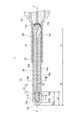
- FIG. 1 is a cross-sectional view for explaining the configuration of the glow plug.
- FIG. 2 is a cross-sectional view taken along the line II-II shown in FIG.
- FIG. 3 is a cross-sectional view taken along the line III-III shown in FIG.
- the glow plug 1 is, for example, a ceramic heater type glow plug, and as shown in FIG. 1, accommodates the ceramic heater 10 and a part of the ceramic heater 10 so that at least the tip is exposed and the outer peripheral surface of the ceramic heater 10 And a metal outer cylinder 20 whose inner circumferential surface is joined via the joint portion 21, and a housing 30.
- the ceramic heater 10 assists the start of the internal combustion engine, and is disposed in the combustion chamber (pre-combustion chamber in the case of a pre-combustion internal combustion engine, combustion chamber of the internal combustion engine in the case of a direct injection internal combustion engine).
- the tip is inserted and fixed to the housing 30 via the outer cylinder 20.
- the ceramic heater 10 is formed of a ceramic.
- the ceramic heater 10 has a conductive ceramic 11 and an insulating ceramic 16 covering the conductive ceramic 11.
- the conductive ceramic 11 is heated in the glow plug 1 by energization, and has a heat generating portion 12 formed in a U shape disposed at the tip, and a lead 14 connected to the rear end of the heat generating portion 12; Have.
- the shape of the heat generating portion 12 is not particularly limited in a cross-sectional view perpendicular to the axis x of the ceramic heater 10, and may take various shapes such as a circle, an ellipse, an oval, and a polygon.
- the heat generating portion 12 has a pair of extending portions 12a and 12b extending in parallel to each other along the axis x of the ceramic heater 10, and a curved portion 12c connecting the extending portions 12a and 12b.
- Heating unit 12 is located within the range of 4.5mm from the tip of the insulating ceramic 16, having dimensions of length l 1 of 3.5mm along the axis x of the ceramic heater 10.
- the heat generating portion 12 is a heat generating resistor having high resistance to the lead 14, and is made of conductive ceramic.
- the heat generating portion 12 is formed of, for example, a material containing carbide, nitride, silicide or the like as a main component including tungsten (W), molybdenum (Mo), titanium (Ti) or the like. It is preferable that the heat generating portion 12 particularly contain tungsten carbide (WC) having inorganic heat conductivity in that it has high heat resistance and low specific resistance.
- WC tungsten carbide
- the heat generating portion 12 preferably contains silicon nitride (Si 3 N 4 ) in addition to the above main component, and the content of silicon nitride (Si 3 N 4 ) is preferably 20% by mass or more.
- the conductor component to be the heat generating portion 12 has a thermal expansion coefficient larger than that of silicon nitride (Si 3 N 4 ) in the insulating ceramic 16 containing silicon nitride ceramics, a tensile stress is usually applied. It is in.
- silicon nitride (Si 3 N 4 ) into the heat generating portion 12 the thermal expansion coefficient is made close to the thermal expansion coefficient of the insulating ceramic 16, and the temperature rise and temperature drop of the ceramic heater 10. The stress due to the difference in the coefficient of thermal expansion can be relaxed.
- the content of silicon nitride (Si 3 N 4 ) contained in the heat generating portion 12 is 40% by mass or less, the resistance value of the heat generating portion 12 can be made relatively small and stable. Therefore, the content of silicon nitride (Si 3 N 4 ) contained in the heat generating portion 12 is preferably 20 to 40% by mass. More preferably, the content of silicon nitride (Si 3 N 4 ) is 25 to 35% by mass.
- boron nitride As a similar additive to the heat generating portion 12, 4 to 12% by mass of boron nitride (BN) may be added instead of silicon nitride (Si 3 N 4 ). Furthermore, in the heat generating portion 12, elements of the fourth, fifth, sixth, seventh and eighth groups of the fourth period of the periodic table of the elements (titanium (Ti), vanadium (V), chromium (Cr), manganese (Mn), iron ( At least one of Fe)) may be contained.
- Ti titanium
- V vanadium
- Cr chromium
- Mn manganese
- Fe At least one of Fe
- the content of elements of titanium (Ti), vanadium (V), chromium (Cr), manganese (Mn), and iron (Fe) in the heat-generating portion 12 is preferably 0.5 mol% or less.
- the lead 14 is connected at its front end to the rear end of the heat generating portion 12 and exposed at its rear end from the insulating ceramic 16.
- the lead 14 includes a positive electrode lead 14 a and a negative electrode lead 14 b.
- the positive electrode side lead 14 a and the negative electrode side lead 14 b are each formed of a conductive ceramic having low resistance to the heat generating portion 12.
- the positive electrode lead 14 a and the negative electrode lead 14 b extend in parallel with each other along the axis x of the ceramic heater 10.
- the positive electrode lead 14a and the negative electrode lead 14b are connected to both ends of the extension portions 12a and 12b of the heat generating portion 12 extending in a U-shape.
- the positive electrode side lead 14 a is connected to the extending portion 12 a of the heat generating portion 12 at the tip.
- the positive electrode side lead 14 a extends inside the insulating ceramic 16 to the rear end of the insulating ceramic 16.
- the positive electrode side lead 14 a is exposed from the insulating ceramic 16 at the rear end of the ceramic heater 10 and is electrically connected to the lead wire 115 through the cap-like connection portion 114.
- the negative electrode lead 14 b has an exposed portion 14 c which is connected to the extending portion 12 b of the heat generating portion 12 at its front end and partially exposed to the outer peripheral surface of the insulating ceramic 16 at its rear end.
- the exposed portion 14 c of the lead 14 is joined to the inner peripheral surface of the outer cylinder 20 by brazing or the like via a joining portion 21 described later.
- the lead 14 is electrically connected to the outer cylinder 20 formed of a conductive metal material through the exposed portion 14 c.
- the exposed portion 14c of the lead 14 functions as a negative electrode.
- the lead 14 preferably contains tungsten carbide (WC), which is an inorganic conductor, as a main component, to which silicon nitride (Si 3 N 4 ) is preferably added so as to have a content of 15% by mass or more.
- WC tungsten carbide
- Si 3 N 4 silicon nitride
- the thermal expansion coefficients of the positive electrode lead 14 a and the negative electrode lead 14 b approach the thermal expansion coefficient of silicon nitride (Si 3 N 4 ) contained in the insulating ceramic 16. be able to.
- the content of silicon nitride is 40% by mass or less, the resistances of the positive electrode lead 14a and the negative electrode lead 14b are reduced and stabilized. Therefore, the content of silicon nitride (Si 3 N 4 ) is preferably 15 to 40% by mass. More preferably, the content of silicon nitride (Si 3 N 4 ) is 20 to 35% by mass.
- an element (titanium (Ti), vanadium (V), chromium (Cr), manganese (Mn), iron (Fe), group 4, 5, 6, 7, 8 of the 4th period of the element periodic table) )) May contain at least one oxide and / or nitride.
- the content of the elements of titanium (Ti), vanadium (V), chromium (Cr), manganese (Mn), and iron (Fe) in the lead 14 is preferably 0.5 mol% or less.
- the lead 14 is preferably a mixture containing, for example, a rare earth element compound such as chromium oxide (Cr 2 O 3 ) of about several tens of PPM, and is a sintered body formed by sintering.
- a rare earth element compound such as chromium oxide (Cr 2 O 3 ) of about several tens of PPM
- the lead 14 is formed of the same material as the heat generating portion 12, but, for example, the lead 14 contains more of the forming material than the heat generating portion 12 or has a larger cross-sectional area than the heat generating portion 12.
- the resistance per unit length is low.
- the insulating ceramic 16 is, for example, a sintered body having a cylindrical outer peripheral surface formed by sintering.
- the insulating ceramic 16 covers the conductive ceramic 11. More specifically, the insulating ceramic 16 covers the heat generating portion 12 and the lead 14. In other words, the heat generating portion 12 and the lead 14 are embedded in the insulating ceramic 16.
- the insulating ceramic 16 has a diameter d of 2.9 to 3.1 mm and a cylindrical outer peripheral surface, and in particular, the diameter d is preferably 2.9 mm.
- the diameter d of the insulating ceramic 16 is the diameter at the portion of the cylindrical outer peripheral surface, and the diameter at the dome-shaped portion is excluded.
- the tip of the curved portion 12c of the heat generating portion 12 the distance between the tip of the insulating ceramic 16 (length) l 2 is about 0.97 mm.
- Insulating ceramic 16 the thin part thickness t 1 of the (the thinnest portion) 16a of the extending portion 12a of the outer peripheral surface and the heating portion 12, and a 12b closest of insulating ceramics 16 in the axial x perpendicular cross section It is in the range of 0.5 to 0.7 mm.
- the thickness t 1 of the thin portion 16a is more preferably a 0.57 ⁇ 0.66 mm.
- “closest” means the outer peripheral surface of the insulating ceramic 16 and the extending portions 12 a and 12 b of the heat generating portion 12 (here, the outer peripheral surfaces of the extending portions 12 a and 12 b).
- Thinned portion 16a as shown in FIG. 2, in a cross section perpendicular to the axis x, the thickness t 1 of the shortest distance to the outer peripheral surface of the heat generating portion 12 from the outer circumferential surface of the insulating ceramic 16 is 0. It is a portion of 5 to 0.7 mm.
- the portion other than the thin portion 16a may be 0.5 to 0.7 mm.
- the thickness t 2 of the insulating ceramic 16 between the positive electrode lead 14 a and the negative electrode lead 14 b and the outer peripheral surface of the insulating ceramic 16 is 0.25 to 0 in the region covering the leads 14. It has a thin portion 16b in the range of .4 mm. The thin portion 16b is more preferably 0.25 to 0.35 mm.
- Thin portion 16b in a cross section perpendicular to the axis x, the thickness t 2 of the shortest distance from the outer peripheral surface of the insulating ceramic 16 to the outer peripheral surface of the lead 14 is 0.25 It is a portion which is ⁇ 0.4 mm.
- the axial x direction length (first length) A from the front end of the insulating ceramic 16 to the rear end of the heat generating portion 12, specifically, the rear ends of the extension portions 12 a and 12 b of the heat generating portion 12 is about 4
- the axial length (second length) B from the tip of the insulating ceramic 16 to the tip of the joint 21 described later is 12 to 20 mm, and the length in the axis x direction of the joint 21 is .5 mm.
- the length (third length) C is 2.8 to 10.8 mm.
- the length A with respect to the length B of the insulating ceramic 16 satisfies the following formula (Formula 1).
- the length A with respect to the length B of the insulating ceramic 16 satisfy the following formula (Formula 3).
- the heat generating portion 12 is located in the range of 4.5 mm in its entirety along the axis x from the tip of the insulating ceramic 16.
- the insulating ceramic 16 made of ceramic enables provision of the ceramic heater 10 having high reliability at the time of rapid temperature rise.
- Specific examples of the ceramics include ceramics having electrical insulation such as oxide ceramics, nitride ceramics, carbide ceramics and the like.
- silicon nitride which is the main component, is excellent in terms of high strength, high toughness, high insulation and heat resistance.
- This silicon nitride ceramic is, for example, 3 to 12% by mass of yttrium oxide (Y 2 O 3 ), ytterbium oxide (Yb 2 O 3 ), eribium oxide (Yb 2 O 3 ) as a sintering aid with respect to silicon nitride as the main component.
- Rare earth element oxides such as Er 2 O 3
- Al 2 O 3 aluminum oxide
- SiO 2 silicon dioxide contained in the sintered body % and comprising as silicon dioxide are mixed (SiO 2), obtained by hot press firing.
- the coefficient of thermal expansion of the silicon nitride ceramic as the base material can be made close to the coefficient of thermal expansion of the heat generating portion 12, and the durability of the ceramic heater 10 can be improved.
- the outer cylinder 20 is, for example, a cylindrical stainless steel such as SUS430. As shown in FIG. 1, the outer cylinder 20 accommodates the ceramic heater 10 in a state in which the tip of the ceramic heater 10 is exposed. In the state where the ceramic heater 10 is accommodated, the ceramic heater 10 and the outer cylinder 20 are provided on the inner peripheral surface of the outer cylinder 20 along the axis x of the ceramic heater 10 for a predetermined length, for example, brazing material such as silver solder. The joint part 21 joined by brazing using is formed.
- the bonding portion 21 is formed by metalizing the outer peripheral surface of the insulating ceramic 16 by brazing of a brazing material such as silver brazing, and has a predetermined length (length C) along the axis x of the ceramic heater 10 Equivalent) is formed between the outer peripheral surface of the ceramic heater 10 and the inner peripheral surface of the outer cylinder 20.
- the joint portion 21 is formed from the front end of the outer cylinder 20 to a position where the insulating ceramic 16 is in contact with the inner peripheral surface of the front end portion 22 of the outer cylinder 20 at the rear end side.
- the joint portion 21 may be in the outer cylinder 20 even if the tip thereof is advanced from the outer cylinder 20 at the axis x.
- the housing 30 is a fixture for a cylinder head of an engine (not shown), and accommodates the ceramic heater 10 together with the outer cylinder 20 as shown in FIG.
- the housing 30 is formed of a thermally conductive metal material having excellent heat dissipation.
- the housing 30 is formed, for example, in a cylindrical shape, and the rear end side of the ceramic heater 10 is partially supported by the outer cylinder 20, and the outer cylinder 20 is disposed inside the housing 30. In this state, the tip end of the ceramic heater 10 protrudes outward from the tip of the housing 30.
- Table 1 shows the diameter d (mm) of the insulating ceramic 16 in the ceramic heater 10, the thickness t 1 (mm) of the thin portion 16a between the heat generating portion 12 and the outer peripheral surface of the insulating ceramic 16, and the lead 14 and the insulation examples 1 and 2 the thickness t 2 of the thin portion 16b that (mm) is the numerical range of the above embodiments between the outer peripheral surface of sexual ceramics 16, except in Comparative example 1 it various specifications and various It shows about the result of simulation.
- Example 1 smaller than the diameter d of the ceramic heater 10 is 3.2mm, Examples 1 and 2 the thickness t 1 of the thin portion 16a is less than 0.7mm, the greater than 3.2mm diameter d, the thin portion 16a
- the temperature rising time up to 1000 ° C. was shorter as compared to Comparative Example 1 in which the thickness t 1 exceeded 0.7 mm.
- Example 2 in which the diameter d is 2.9 mm and the thickness t 1 is 0.57 mm, the temperature rising time up to 1000 ° C. is less than 1 second, and excellent temperature rising characteristics are exhibited.
- the temperatures of Examples 1 and 2 in the heat generating portion 12 two seconds after energization are both higher than the temperature of Comparative Example 1, and in Example 2 exceed 1500 ° C .; It turned out that it has a temperature characteristic.
- the thickness t 1 of the thin portion 16a is a condition of 0.5 ⁇ 0.7 mm It was found that when satisfied, the temperature rising characteristics are excellent. Furthermore, it is more preferable that the diameter d satisfies the condition of 2.9 to 3.1 mm.
- the thickness t 1 is less than 0.5 mm, when the progress in corrosion of the insulating ceramic 16 with the passage of time, there is a possibility that the heat generating portion 12 is exposed at an early stage.
- tungsten (W) contained in the material of the heat generating portion 12 may be oxidized, and the heat generating portion 12 may be broken.
- the second embodiment achieves early temperature rise and power consumption reduction while avoiding the early exposure of the heat generating portion 12 and achieving the long life of the glow plug 1.
- Table 2 shows the same diameter d (mm) of the insulating ceramic 16 as in Example 2, the thickness t 1 (mm) of the thin portion 16a between the heat generating portion 12 and the outer peripheral surface of the insulating ceramic 16, The thickness t 2 (mm) of the thin portion 16 b between the lead 14 and the outer circumferential surface of the insulating ceramic 16, the axial length B from the tip of the insulating ceramic 16 to the tip of the joint 21, bonding
- the axial length C of the part 21 shows the result of various specifications and various simulations of Examples 3 to 5 and Comparative Examples 2 and 3 different from each other.
- the axial length A from the front end of the insulating ceramic 16 to the rear end of the heat generating portion 12 is the same in Examples 3 to 5 and Comparative Examples 1 and 2.
- the temperature at a point 2 mm from the tip of the ceramic heater 10 after 60 seconds of simulation start has a large proportion of the ceramic heater 10 exposed from the outer cylinder 20, that is, brazing with the outer cylinder 20 It was found that the smaller the area of the ceramic heater 10 being made, the higher.
- the ratio (A / B) of the length A to the length B in the insulating ceramic 16 is 0.2 to 0.4, and the insulating ceramic 16
- the ceramic heater 10 satisfying the ratio of the length C to the length B + C (C / B + C) in the range of 0.1 to 0.5 reached a temperature of about 1200 ° C. after 60 seconds.
- Example 3 has a value of A / B of 0.375, C / B + C has a value of about 0.474, and Example 4 has a value of A / B of about 0.321; The value of B + C was about 0.386, the value of A / B was 0.225, and the value of C / B + C was about 0.123. Even when Comparative Examples 2 and 3 which do not satisfy the conditions of any of the above-mentioned ratios and Examples 3 to 5 are compared, it is found that the temperature rise characteristics are excellent in Examples 3 to 5.
- the power consumption after 60 seconds of the simulation start becomes 29 W or less when the condition of the above ratio is satisfied as in the examples 3 to 5, and the power consumption in the examples 3 to 5 is the consumption in the comparative examples 2 and 3 It was found to be small compared to the power.
- Table 3 shows the same diameter d (mm) of the insulating ceramic 16 as in Example 2, the thickness t 1 (mm) of the thin portion between the heat generating portion 12 and the outer peripheral surface of the insulating ceramic 16, and the lead.
- Example 6 and Comparative Example 4 having a thickness t 2 (mm) of the thin portion 16a between the outer peripheral surface of the insulating ceramic 16 and the heat generating portion 12 and having different lengths l 1 and Comparative Example
- Comparative Example 5 having the same diameter d (mm), thickness t 1 (mm), and thickness t 2 (mm) as 1 and having the same length 11 of the heat generating portion 12 as in Example 6 The original and simulation results are shown.
- Example 6 in which the axial direction x length A from the front end of the insulating ceramic 16 to the rear end of the heat generating portion 12 is 4.5 mm or less (A ⁇ 4.5 (mm))
- the temperature rising time to 1000 ° C. was 0.98 seconds, which was less than 1 second.
- the temperature rise time up to 1000 ° C. in the ceramic heater 10 is shortened if the axial x direction length A from the front end of the insulating ceramic 16 to the rear end of the heat generating portion 12 is 4.5 mm or less It turned out that
- the thickness t 1 of the thin portion 16a of the outer peripheral surface of the insulating ceramic 16 and the heating portion 12 is closer is in the range of 0.5 ⁇ 0.7 mm.
- the thickness t 1 of the thin portion 16a is preferable to be 0.57 ⁇ 0.66 mm, further, it is more preferred diameter d of the insulating ceramic 16 is 2.9 ⁇ 3.1 mm.
- the axial x direction length A from the front end of the insulating ceramic 16 to the rear ends of the extension portions 12a and 12b of the heat generating portion 12 is 4.5 mm or less, in other words, within 4.5 mm from the front end of the insulating ceramic 16 Since the entire heat generating portion 12 is positioned, the time until the temperature reaches 1000 ° C. is the length A in the axial line x direction from the front end of the insulating ceramic 16 to the rear ends of the extension portions 12 a and 12 b of the heat generating portion 12. Can be shortened compared to when it exceeds 4.5 mm.
- Equation 3 and Equation 4 Is more preferable from the viewpoint of temperature rise characteristics and power consumption reduction.
- the present invention is not limited to the above embodiment.
- the cross-sectional shape of the ceramic heater 10 perpendicular to the axis x is not limited to a circle, but may be another shape such as an ellipse or a polygon.
- the stepped surface shape of the heat generating portion 12 and the lead 14 is not limited to an elliptical shape, and may be another shape such as a circle or a polygon such as a rectangle.
Landscapes
- Engineering & Computer Science (AREA)
- Chemical & Material Sciences (AREA)
- Combustion & Propulsion (AREA)
- Mechanical Engineering (AREA)
- General Engineering & Computer Science (AREA)
- Resistance Heating (AREA)
Abstract
L'objet de la présente invention est de réduire au minimum la consommation d'énergie tout en obtenant une augmentation rapide de la puissance. Une bougie de préchauffage (1) selon la présente invention est caractérisée en ce qu'elle comprend un élément chauffant en céramique (10) qui a une céramique électroconductrice (11) et une céramique isolante (16) qui recouvre la céramique électroconductrice (11) ; la céramique électroconductrice (11) ayant une partie de production de chaleur (12) disposée à l'extrémité distale et un fil (14) relié à l'extrémité arrière de l'unité de production de chaleur (12) ; et la partie la plus mince (16a) de la céramique isolante (16), au niveau de laquelle l'unité de production de chaleur (12) et la surface périphérique externe de la céramique isolante (16) sont les plus proches les unes des autres dans une section transversale perpendiculaire à l'axe du dispositif de chauffage en céramique (10), présente une épaisseur comprise entre 0,5 et 0,7 mm.
Priority Applications (3)
| Application Number | Priority Date | Filing Date | Title |
|---|---|---|---|
| JP2019556117A JPWO2019102708A1 (ja) | 2017-11-21 | 2018-09-26 | グロープラグ |
| EP18880219.3A EP3736493B1 (fr) | 2017-11-21 | 2018-09-26 | Bougie de préchauffage |
| SI201831099T SI3736493T1 (sl) | 2017-11-21 | 2018-09-26 | Žarilna svečka |
Applications Claiming Priority (2)
| Application Number | Priority Date | Filing Date | Title |
|---|---|---|---|
| JP2017223485 | 2017-11-21 | ||
| JP2017-223485 | 2017-11-21 |
Publications (1)
| Publication Number | Publication Date |
|---|---|
| WO2019102708A1 true WO2019102708A1 (fr) | 2019-05-31 |
Family
ID=66630594
Family Applications (1)
| Application Number | Title | Priority Date | Filing Date |
|---|---|---|---|
| PCT/JP2018/035539 Ceased WO2019102708A1 (fr) | 2017-11-21 | 2018-09-26 | Bougie de préchauffage |
Country Status (4)
| Country | Link |
|---|---|
| EP (1) | EP3736493B1 (fr) |
| JP (1) | JPWO2019102708A1 (fr) |
| SI (1) | SI3736493T1 (fr) |
| WO (1) | WO2019102708A1 (fr) |
Citations (10)
| Publication number | Priority date | Publication date | Assignee | Title |
|---|---|---|---|---|
| JPS62731A (ja) * | 1985-06-27 | 1987-01-06 | Jidosha Kiki Co Ltd | デイ−ゼルエンジン用グロ−プラグ |
| JPH0220293U (fr) * | 1988-07-26 | 1990-02-09 | ||
| JPH07151332A (ja) * | 1993-11-29 | 1995-06-13 | Kyocera Corp | セラミックグロープラグ |
| JPH07220859A (ja) * | 1994-01-31 | 1995-08-18 | Kyocera Corp | セラミック発熱体 |
| JP2001227744A (ja) * | 2000-02-14 | 2001-08-24 | Denso Corp | セラミックグロープラグ |
| JP2002334768A (ja) | 2001-05-02 | 2002-11-22 | Ngk Spark Plug Co Ltd | セラミックヒータ及びそれを用いたグロープラグ |
| JP2004061041A (ja) * | 2002-07-31 | 2004-02-26 | Kyocera Corp | セラミックグロープラグ |
| JP2005315447A (ja) * | 2004-04-27 | 2005-11-10 | Kyocera Corp | セラミックヒーターおよびグロープラグ |
| JP2009287920A (ja) * | 2009-09-09 | 2009-12-10 | Ngk Spark Plug Co Ltd | グロープラグ |
| WO2017038694A1 (fr) * | 2015-08-29 | 2017-03-09 | 京セラ株式会社 | Élément chauffant et bougie de préchauffage pourvue de celui-ci |
Family Cites Families (4)
| Publication number | Priority date | Publication date | Assignee | Title |
|---|---|---|---|---|
| JP3766786B2 (ja) * | 2000-12-28 | 2006-04-19 | 日本特殊陶業株式会社 | セラミックヒータ及びそれを備えるグロープラグ |
| JP4794338B2 (ja) * | 2006-03-29 | 2011-10-19 | 京セラ株式会社 | セラミックヒータ |
| JP5171335B2 (ja) * | 2008-03-25 | 2013-03-27 | 日本特殊陶業株式会社 | セラミックヒータ及びグロープラグ |
| JP5280877B2 (ja) * | 2009-02-03 | 2013-09-04 | 日本特殊陶業株式会社 | セラミックヒータ及びグロープラグ |
-
2018
- 2018-09-26 SI SI201831099T patent/SI3736493T1/sl unknown
- 2018-09-26 EP EP18880219.3A patent/EP3736493B1/fr active Active
- 2018-09-26 JP JP2019556117A patent/JPWO2019102708A1/ja active Pending
- 2018-09-26 WO PCT/JP2018/035539 patent/WO2019102708A1/fr not_active Ceased
Patent Citations (10)
| Publication number | Priority date | Publication date | Assignee | Title |
|---|---|---|---|---|
| JPS62731A (ja) * | 1985-06-27 | 1987-01-06 | Jidosha Kiki Co Ltd | デイ−ゼルエンジン用グロ−プラグ |
| JPH0220293U (fr) * | 1988-07-26 | 1990-02-09 | ||
| JPH07151332A (ja) * | 1993-11-29 | 1995-06-13 | Kyocera Corp | セラミックグロープラグ |
| JPH07220859A (ja) * | 1994-01-31 | 1995-08-18 | Kyocera Corp | セラミック発熱体 |
| JP2001227744A (ja) * | 2000-02-14 | 2001-08-24 | Denso Corp | セラミックグロープラグ |
| JP2002334768A (ja) | 2001-05-02 | 2002-11-22 | Ngk Spark Plug Co Ltd | セラミックヒータ及びそれを用いたグロープラグ |
| JP2004061041A (ja) * | 2002-07-31 | 2004-02-26 | Kyocera Corp | セラミックグロープラグ |
| JP2005315447A (ja) * | 2004-04-27 | 2005-11-10 | Kyocera Corp | セラミックヒーターおよびグロープラグ |
| JP2009287920A (ja) * | 2009-09-09 | 2009-12-10 | Ngk Spark Plug Co Ltd | グロープラグ |
| WO2017038694A1 (fr) * | 2015-08-29 | 2017-03-09 | 京セラ株式会社 | Élément chauffant et bougie de préchauffage pourvue de celui-ci |
Non-Patent Citations (1)
| Title |
|---|
| See also references of EP3736493A4 |
Also Published As
| Publication number | Publication date |
|---|---|
| SI3736493T1 (sl) | 2024-06-28 |
| EP3736493A1 (fr) | 2020-11-11 |
| EP3736493B1 (fr) | 2024-03-13 |
| EP3736493A4 (fr) | 2021-06-02 |
| JPWO2019102708A1 (ja) | 2020-10-22 |
Similar Documents
| Publication | Publication Date | Title |
|---|---|---|
| JP5166451B2 (ja) | セラミックヒータおよびグロープラグ | |
| JP3044630B2 (ja) | セラミックヒータ型グロープラグ | |
| JPS62731A (ja) | デイ−ゼルエンジン用グロ−プラグ | |
| JPS62252829A (ja) | デイ−ゼルエンジン用グロ−プラグ | |
| JP6835604B2 (ja) | ヒータ | |
| JP3044632B2 (ja) | セラミックヒータ型グロープラグ | |
| WO2019102708A1 (fr) | Bougie de préchauffage | |
| JP2004061041A (ja) | セラミックグロープラグ | |
| JP2019090567A (ja) | グロープラグ用のセラミックヒータ及びグロープラグ | |
| JP6592103B2 (ja) | ヒータおよびこれを備えたグロープラグ | |
| JP7037338B2 (ja) | グロープラグ | |
| KR20130016353A (ko) | 히터 및 이것을 구비한 글로 플러그 | |
| JP5307487B2 (ja) | セラミックヒータ、グロープラグ、及び、内燃機関 | |
| JP6725653B2 (ja) | ヒータおよびこれを備えたグロープラグ | |
| JP4064277B2 (ja) | セラミックヒータ | |
| JP7032954B2 (ja) | ヒータ | |
| CN112314051B (zh) | 加热器以及具备该加热器的电热塞 | |
| JP6844995B2 (ja) | ヒータ | |
| JP6603321B2 (ja) | ヒータおよびこれを備えたグロープラグ | |
| JP6952395B2 (ja) | ヒータ | |
| JP6923425B2 (ja) | ヒータ | |
| JPH0228045B2 (fr) | ||
| JP5829691B2 (ja) | ヒータおよびこれを備えたグロープラグ | |
| JP7000241B2 (ja) | ヒータ | |
| JPS62141424A (ja) | デイ−ゼルエンジン用グロ−プラグ |
Legal Events
| Date | Code | Title | Description |
|---|---|---|---|
| 121 | Ep: the epo has been informed by wipo that ep was designated in this application |
Ref document number: 18880219 Country of ref document: EP Kind code of ref document: A1 |
|
| ENP | Entry into the national phase |
Ref document number: 2019556117 Country of ref document: JP Kind code of ref document: A |
|
| NENP | Non-entry into the national phase |
Ref country code: DE |
|
| ENP | Entry into the national phase |
Ref document number: 2018880219 Country of ref document: EP Effective date: 20200622 |