WO2019102737A1 - Débitmètre - Google Patents
Débitmètre Download PDFInfo
- Publication number
- WO2019102737A1 WO2019102737A1 PCT/JP2018/037991 JP2018037991W WO2019102737A1 WO 2019102737 A1 WO2019102737 A1 WO 2019102737A1 JP 2018037991 W JP2018037991 W JP 2018037991W WO 2019102737 A1 WO2019102737 A1 WO 2019102737A1
- Authority
- WO
- WIPO (PCT)
- Prior art keywords
- support
- substrate
- flow meter
- circuit board
- housing
- Prior art date
- Legal status (The legal status is an assumption and is not a legal conclusion. Google has not performed a legal analysis and makes no representation as to the accuracy of the status listed.)
- Ceased
Links
Images







Classifications
-
- G—PHYSICS
- G01—MEASURING; TESTING
- G01F—MEASURING VOLUME, VOLUME FLOW, MASS FLOW OR LIQUID LEVEL; METERING BY VOLUME
- G01F1/00—Measuring the volume flow or mass flow of fluid or fluent solid material wherein the fluid passes through a meter in a continuous flow
- G01F1/68—Measuring the volume flow or mass flow of fluid or fluent solid material wherein the fluid passes through a meter in a continuous flow by using thermal effects
- G01F1/684—Structural arrangements; Mounting of elements, e.g. in relation to fluid flow
-
- G—PHYSICS
- G01—MEASURING; TESTING
- G01F—MEASURING VOLUME, VOLUME FLOW, MASS FLOW OR LIQUID LEVEL; METERING BY VOLUME
- G01F1/00—Measuring the volume flow or mass flow of fluid or fluent solid material wherein the fluid passes through a meter in a continuous flow
- G01F1/68—Measuring the volume flow or mass flow of fluid or fluent solid material wherein the fluid passes through a meter in a continuous flow by using thermal effects
- G01F1/684—Structural arrangements; Mounting of elements, e.g. in relation to fluid flow
- G01F1/6842—Structural arrangements; Mounting of elements, e.g. in relation to fluid flow with means for influencing the fluid flow
-
- G—PHYSICS
- G01—MEASURING; TESTING
- G01F—MEASURING VOLUME, VOLUME FLOW, MASS FLOW OR LIQUID LEVEL; METERING BY VOLUME
- G01F15/00—Details of, or accessories for, apparatus of groups G01F1/00 - G01F13/00 insofar as such details or appliances are not adapted to particular types of such apparatus
- G01F15/006—Details of, or accessories for, apparatus of groups G01F1/00 - G01F13/00 insofar as such details or appliances are not adapted to particular types of such apparatus characterised by the use of a particular material, e.g. anti-corrosive material
-
- G—PHYSICS
- G01—MEASURING; TESTING
- G01F—MEASURING VOLUME, VOLUME FLOW, MASS FLOW OR LIQUID LEVEL; METERING BY VOLUME
- G01F15/00—Details of, or accessories for, apparatus of groups G01F1/00 - G01F13/00 insofar as such details or appliances are not adapted to particular types of such apparatus
- G01F15/14—Casings, e.g. of special material
-
- G—PHYSICS
- G01—MEASURING; TESTING
- G01F—MEASURING VOLUME, VOLUME FLOW, MASS FLOW OR LIQUID LEVEL; METERING BY VOLUME
- G01F15/00—Details of, or accessories for, apparatus of groups G01F1/00 - G01F13/00 insofar as such details or appliances are not adapted to particular types of such apparatus
- G01F15/18—Supports or connecting means for meters
-
- G—PHYSICS
- G01—MEASURING; TESTING
- G01F—MEASURING VOLUME, VOLUME FLOW, MASS FLOW OR LIQUID LEVEL; METERING BY VOLUME
- G01F5/00—Measuring a proportion of the volume flow
Definitions
- the present invention relates to a flow meter.
- a sensor module and a semiconductor module including an electronic circuit such as an electronic control unit are mounted on an internal combustion engine such as a car.
- a circuit board on which semiconductor components are mounted is used for these modules, and the circuit board is housed inside a housing, and a conductor terminal is used for signal input and output with the outside.
- the conductor terminal is, for example, a bonding wire or a press-fit terminal. In connection using a bonding wire, a wire of gold, aluminum or the like is welded to a semiconductor module, a circuit board or the like using heat or ultrasonic waves to achieve electrical connection.
- an elastic deformation area which is elastically deformed is previously formed on the press-fit terminal, and the elastic deformation area is press-fit into a through hole formed in a circuit board to electrically connect I am trying to Then, in the connection using the press-fit terminal, when press-fitting the elastic deformation region of the press-fit terminal into the through hole, an area in which the dimension of the through hole is smaller than the dimension of the press fit terminal is formed. As a result, the elastic deformation region is deformed to make an electrical connection.
- Patent Document 1 discloses a flow rate measuring device which is installed in a device insertion hole formed in a pipe and measures the flow rate of the fluid to be measured passing through the pipe passage, and protrudes to the outside of the pipe at the proximal end.
- a base body having a connector, a resin base including a flange provided radially extending from the base body and fitted in the device insertion hole; and a plate provided so as to partially overlap the base body.
- a flow rate detecting element provided on the plate to be exposed and detecting the flow rate of the fluid to be measured; a circuit board provided on the connector side of the plate and having a control circuit for processing a signal from the flow rate detecting element;
- a circuit cover which covers a circuit board, a resin cover having a fluid passage groove which forms a measurement passage in cooperation with the plate, and a connector which is provided inside the circuit housing.
- the inner wall surface of the flange and the outer peripheral wall surface of the cover facing the inner wall surface, connecting the flange and the cover, vibration of the pipe
- a flow rate measuring apparatus comprising: deformation suppressing means for suppressing deformation of the base body caused by the above.
- a flowmeter includes a flat substrate, a housing which houses the substrate and which is open at least in one surface, and a cover which covers the substrate and covers the open surface of the housing.
- a supporting member supporting the substrate in contact with the cover and the substrate, and a fixing portion connecting the substrate and the housing, the first member being formed by dividing the substrate into two at the center in the longitudinal direction In the region and the second region, the support is disposed in the first region, and the fixing portion is disposed in the second region.
- FIG. 1 3 shows the state before press fitting the press fit terminal 8 into the through hole 6
- FIG. 3 (b) shows the state after press fitting the press fit terminal 8 into the through hole 6.
- Cross section of flow meter 100 in modification 1 Cross section of flow meter 100 in modification 3
- Cross section of flow meter 100 in modification 5 Top view of flow meter 100 in modification 6 VIII-VIII sectional view of FIG. 7
- Top view of flow meter 100 in modification 7 XX cross section of FIG. 9 Plan view of the flowmeter 100A according to the second embodiment XII-XII sectional view of FIG.
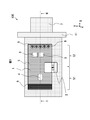
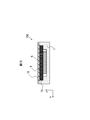
- FIG. 1 is a plan view of the flow meter 100
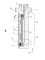
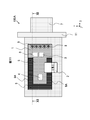
- FIG. 2 is a cross-sectional view showing a structure cut along line II-II shown in FIG.
- FIG. 1 shows the cover 10 shown in FIG. 2 in a removed state.
- the X axis, the Y axis, and the Z axis are defined as shown in the lower right of FIG. These three axes are common to all the drawings in the present embodiment.
- the left-right direction of FIG. 1, that is, the X-axis direction will be referred to as the longitudinal direction of the circuit board 5 described later.
- the circuit board 5 is divided into two at the center in the longitudinal direction, and the left side shown in FIG. 1 is called a first area 51, and the right side is called a second area 52. Further, the front surface of the circuit board 5 in the Z-axis direction is called front and back, and the upper side of FIG. 2 is called the front surface 53 of the circuit board 5 and the lower side is called the back surface 54 of the circuit board 5.
- the flowmeter 100 includes a circuit board module 1 on which various sensors and the like are mounted, a housing 7 and a cover 10 shown in FIG.
- the circuit board module 1 includes a flow meter chip 2, a pressure sensor 3, a humidity sensor 4, a flat circuit board 5, a through hole 6, and a support 9.
- the flow meter chip 2, the pressure sensor 3, and the humidity sensor 4 are mounted on the circuit board 5 by solder or the like.
- the longitudinal direction of the support 9 is arranged in the short direction of the circuit board 5.
- the through holes 6 are holes penetrating the circuit board 5 from the front to the back.
- the through holes 6 are provided on the right side in FIG. 1, that is, the second area 52, and are used for bonding with the press-fit terminals 8 described later.
- the through holes 6 are preferably formed at the end of the circuit board 5, that is, at the right end of the circuit board 5 in FIG. 2, but may be in the second region 52. Since the through hole 6 is a hole, forming the through hole 6 at the end of the circuit board 5 means providing a thin portion capable of maintaining the shape of the hole and then making the through hole 6 as far as possible the end of the circuit board 5 It means to provide in the department.
- the through hole 6 forms a fixing portion 200 together with a press-fit terminal 8 described later.
- the fixing portion 200 is formed below the circuit board 5 in FIG.
- the support 9 is provided on the left side in FIG. 1, that is, the first area 51, and on the upper side of FIG. 2, that is, on the surface of the circuit board 5.
- the support 9 has a substantially rectangular parallelepiped shape.
- the support 9 is in contact with the circuit board 5 and the cover 10 to suppress vibration and deformation of the circuit board 5.
- the support 9 is preferably provided at the end of the circuit board 5.
- the flow meter chip 2 is disposed substantially at the center of the circuit board 5 in the longitudinal direction
- the pressure sensor 3 is disposed in the second area 52
- the humidity sensor 4 is disposed in the first area 51. Is not particularly limited.
- the housing 7 is provided with a press fit terminal 8 and a flange portion 11.
- the press fit terminal 8 is insert molded in the housing 7.
- the "press fit terminal” is also referred to as a "press fit pin”.
- the fixing portion 200 fixes the back surface 54 of the circuit board 5 to the housing 7.
- the flange portion 11 is a fixed portion of the flow meter 100. Flowmeter 100 is installed, for example, in an intake pipe of an internal combustion engine of a car, and flange portion 11 is physically connected to the intake pipe.
- the cover 10 shown in FIG. A flow path of air is formed in the housing 7, and the air flow rate is measured by installing the flow meter chip 2 on the flow path.
- the pressure and humidity inside the flow meter 100 are measured by the pressure sensor 3 and the humidity sensor 4 respectively.
- an electronic component or the like for signal processing such as a temperature measurement sensor or a microcomputer (not shown) may be mounted on the circuit board 5.
- FIG. 3A is a view showing a state before press fitting the press fit terminal 8 into the through hole 6, and FIG. 3B shows a state after press fitting the press fit terminal 8 into the through hole 6.
- the press fit terminal 8 includes an elastic deformation portion 12.
- the through holes 6 of the circuit board 5 have conductor foils 13.
- the elastically deformable portion 12 of the press-fit terminal 8 deforms and contacts the conductor foil 13 on the inner periphery of the through hole 6 of the circuit board 5.
- the press-fit terminal 8 are electrically and mechanically connected.
- the press fit terminal 8 is electrically connected to the wiring to the external device and fixed to the housing 7 by insert molding. Therefore, by electrically and mechanically connecting circuit board 5 and press-fit terminal 8, circuit board 5 is electrically connected to an external device, and circuit board 5 is mechanically connected to housing 7. Ru. Since the through holes 6 pass through the front and back of the circuit board 5, it can be understood that the fixing portion 200 is also present on the surface 53 of the circuit board 5. However, since fixing of the circuit board 5 to the housing 7 is performed on the back surface 54 of the circuit board 5, in the present embodiment, the fixing portion 200 is assumed to be present on the back surface 54 of the circuit board 5.
- the intake pipe of the internal combustion engine of the automobile and the flow meter 100 are connected by the flange portion 11 of the housing 7 shown in FIG. 1, and when the vibration occurs, the flange portion 11 becomes the starting point of the vibration.
- the displacement amplitude due to the vibration is particularly large at the end of the circuit board 5 far from the flange portion 11, that is, the left end of the circuit board 5 in FIG.
- the generated stress in the vicinity of the through hole 6 on the circuit board 5 is increased.
- the flowmeter 100 includes the support 9, and the support 9 is in the positional relationship between the fixed portion 200 and the front and back, and the fixed portion 200 is provided on the opposite side in the longitudinal direction, vibration of the circuit board 5 is reduced. Be done.
- the circuit board 5 may be deformed so as to be warped to the cover side starting from the press fit terminal 8 side due to vibration.
- the support 9 suppresses deformation of the substrate. Thereby, it is possible to suppress an increase in the generated stress in the vicinity of the through hole 6 of the circuit board 5 in contact with the press-fit terminal 8.
- the circuit board surface on the opposite side where the support 9 is in contact with the circuit board 5 is in contact with the housing 7, when the circuit board 5 is deformed on the opposite side to the cover, the deformation is suppressed. Thereby, it is possible to suppress an increase in the generated stress in the vicinity of the through hole 6 of the circuit board 5 in contact with the press-fit terminal 8.
- the contact portion between the housing 7 and the circuit board 5, that is, the portion of the housing 7 indicated by reference numeral 71 and reference numeral 72 in FIG. 2 may be bonded to the circuit board 5.
- a material of the circuit board 5 for example, a composite material formed by impregnating resin of woven glass fiber can be used.
- a metal such as copper can be used.
- a thermosetting resin or a thermoplastic resin, for example, a hot melt resin can be used.
- a material having a Young's modulus of 10 MPa or more is desirable for the support 9. The basis of this figure will be described later.
- a material of the cover 10 for example, glass fiber, resin containing particles, metal such as aluminum, or the like can be used.
- Examplementation of support 9 A method of stably mounting the support 9 on the circuit board 5 and the cover 10 will be described. First, sensors such as the flow meter chip 2 and the pressure sensor 3 and the humidity sensor 4 and other electronic components such as a microcomputer are mounted on the circuit board 5 by soldering or the like. Thereafter, the support 9 is formed at the end of the first region 51 of the surface 53 of the circuit board 5 by hot melt molding. Thereby, the circuit board 5 and the support 9 are bonded.
- the circuit board 5 on which the support 9 is mounted is crimped to the press-fit terminal 8 of the housing 7.
- the circuit board 5 is fixed to the housing 7 using the fixing portion 200.
- the housing 7 and the cover 10 are bonded.
- the support 9 is fixed between the circuit board 5 and the housing 7 in a state of being compressed in the Z-axis direction. That is, the width in the Z-axis direction in the natural state of the support 9 is wider than the gap between the circuit board 5 and the housing 7.
- the support 9 may be adhesively bonded to the cover 10 to further improve the fixing property.
- the formation of the support 9 on the circuit board 5 and the fixing of the circuit board 5 to the housing 7 may be reversed in order.
- the flow meter 100 accommodates the flat circuit board 5 and the circuit board 5, and a housing 7 having at least one open surface, and a cover for covering the circuit board 5 and covering the open surface of the housing 7. 10, a support 9 for supporting the circuit board 5 in contact with the cover 10 and the circuit board 5, and a fixing portion 200 for connecting the circuit board 5 and the housing 7 to each other.
- the support 9 is disposed in the first region 51
- the fixing portion 200 is disposed in the second region 52.
- the flowmeter 100 includes a support 9 for supporting or fixing the circuit board 5 and a fixing portion 200 in each of the first area 51 and the second area 52 obtained by dividing the circuit board 5 in the longitudinal direction. Therefore, the deformation of the circuit board 5 due to the vibration applied from the outside can be suppressed, the load on the fixed portion 200 can be reduced, and the reliability of the flow meter 100 can be improved. In addition, when a press-fit terminal is used for the fixing portion 200, it can be connected more easily than a bonding wire, and there is an effect of process shortening and part reduction.
- the fixing portion 200 and the support 9 are disposed at the end of the circuit board 5. Therefore, the vibration of the circuit board 5 can be effectively suppressed.
- the fixing unit 200 doubles as the electrical connection between the circuit board 5 and the external device. Therefore, since it is not necessary to separately connect a wire or the like for electrical connection, the configuration of the flow meter 100 is simple.
- the support 9 is on the front side of the circuit board 5, and the fixing portion 200 is on the back side of the circuit board 5. Therefore, the vibration of the circuit board 5 can be effectively suppressed.
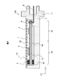
- FIG. 4 is a cross-sectional view of the flow meter 100 in the first modification.
- the support 9 is disposed only on the surface 53 of the circuit board 5, but as shown in FIG. 4, the back support 91 which is the second support is also on the back 54 of the circuit board 5. It may be distributed.
- the back support 91 may have the same material and shape as the support 9 or may have different materials and different shapes from the support 9. However, the back support 91 is also disposed between the housing 7 and the circuit board 5 in a compressed state.
- the material of the support 9 is a thermoplastic resin or a thermosetting resin.
- the support 9 may be a metal spring.
- a material having a Young's modulus of 10 MPa or more is desirable.
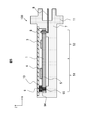
- FIG. 5 is a cross-sectional view of the flow meter 100 in the third modification.
- the circuit board 5 in the modification 3 is provided with a resin filling hole 55 at the end of the first region 51 as shown in FIG.
- the resin filling holes 55 are filled with a resin at the time of hot melt molding to form a filled support 94.
- the filling support 94 is integrally formed with the support 9. Therefore, the support 9 is more firmly fixed to the circuit board 5 by the anchor effect of the filling support 94.
- the circuit board 5 is provided with a resin filling hole 55 which is a hole in a region in contact with the support 9.
- the resin filling hole 55 is formed with a filled support 94 integrally formed with the support 9. Therefore, the support 9 can be fixed to the circuit board 5 more firmly by the anchor effect.
- the support 9 may be mounted by being attached to the circuit board 5 using an adhesive.
- the support 9 may be attached to the cover 10 using an adhesive, and the support 9 may be pressed against the circuit board 5 by fixing the cover 10 to the housing 7.
- FIG. 6 is a cross-sectional view of the flow meter 100 in the fifth modification.
- the support 9 has a substantially rectangular parallelepiped shape, but the cross section of the support 9 may be trapezoidal as shown in FIG.
- the base is a trapezoid whose base is longer than the upper side, and the area in contact with the support 9 and the cover 10 is smaller than the area in which the support 9 and the circuit board 5 are in contact.
- the area in which the support 9 and the cover 10 are in contact is smaller than the area in which the support 9 and the circuit board 5 are in contact. Since the cross section of the support 9, that is, the projection image on the XZ plane shown in FIG. 6 is not rectangular, the support 9 can be easily compressed by the circuit board 5 and the cover 10 at the time of mounting. Further, since a large area in which the support 9 and the circuit board 5 are in contact, which is the area of the surface fixed in the previous step, can be assembled efficiently.
- FIG. 7 is a plan view of the flow meter 100 in the modification 6, and FIG. 8 is a cross-sectional view showing a structure cut along line VIII-VIII shown in FIG.
- the support 9 in the sixth modification has a recess 93 as shown in FIGS. 7 and 8.
- the cover 10 in the sixth modification includes a convex portion 10A as shown in FIG.
- the convex portion 10A and the concave portion 93 are formed in dimensions that can be fitted, and both are fitted.
- the dimensions of the convex portion 10A and the concave portion 93 may be in a so-called close fit relationship or an intermediate fit relationship.
- the unevenness of the support 9 and the cover 10 may be reversed.
- the support 9 includes the recess 93 on the surface in contact with the cover 10.
- the cover 10 includes a convex portion 10A fitted with the concave portion 93.
- the relative position between the support 9 and the cover 10 in the X-axis direction is regulated by the concave portion 93 and the convex portion 10A, so that deformation of the circuit board 5 due to vibration can be suppressed.
- FIG. 9 is a plan view of the flow meter 100 in the seventh modification.
- FIG. 10 is a cross-sectional view showing a structure cut along line XX shown in FIG.
- the longitudinal direction of the support 9 is arranged in the short direction of the circuit board 5.
- the length of the support 9 in the Y direction in the seventh modification is longer than the length of the circuit board 5 in the Y direction, and the housing 7 has a notch 73 fitted to the support 9.
- the longitudinal direction of the support 9 is arranged in the short direction of the circuit board 5.
- the longitudinal dimension of the support 9 is longer than the lateral dimension of the circuit board 5.
- the housing 7 is provided with a notch 73 fitted with the support 9. Therefore, the relative position between the support 9 and the housing 7 in the X-axis direction is restricted, so that deformation of the circuit board 5 due to vibration can be suppressed.
- FIGS. A second embodiment of a flow meter according to the present invention will be described with reference to FIGS.
- the same components as in the first embodiment will be assigned the same reference numerals and differences will be mainly described.
- the points that are not particularly described are the same as in the first embodiment.
- the present embodiment differs from the first embodiment mainly in that the support extends in the longitudinal direction.
- FIG. 11 is a plan view of a flowmeter 100A according to the second embodiment
- FIG. 12 is a cross-sectional view showing a structure cut along line XII-XII shown in FIG.
- the flowmeter 100A is adjacent to the support 9 in addition to the support 9 in the first embodiment and on the outer periphery of the circuit board 5.
- An extending portion 9A is provided along the right side in the longitudinal direction, that is, in the positive direction along the X-axis.
- the extending portion 9A reaches the second region 52. That is, in the outer peripheral portion of the surface 53 of the circuit board 5 and the first region 51, the support 9 or the extending portion 9A is present.
- the material of the extending portion 9A and the method of forming the same are the same as those of the support 9.
- the stretching portion 9A is formed by hot melt molding in the same manner as the support 9 at the timing when the support 9 is formed.
- the support 9 and the extending portion 9A may be separated or may be integrally formed.
- the support area by the extending portion 9A is increased, so that the effect of pressing the circuit board 5 at the time of substrate deformation due to vibration is enhanced.
- the cover 10 in contact with the support 9 and the extension portion 9A is also deformed by vibration, the following concerns arise if the elastic modulus of the support 9 is too high in this embodiment. That is, there is a possibility that the deformation of the cover 10 is transmitted to the circuit board 5 without compressive deformation of the support 9 and the extension portion 9A, and the circuit board 5 is pressed excessively. Therefore, in the present embodiment, it is desirable that the elastic modulus of the support 9 and the stretching portion 9A be 10 MPa to 1000 MPa. Further, a spring having a modulus of elasticity of 10 MPa to 1000 MPa may be used for the support 9 and the extension portion 9A.
- the flowmeter 100A is provided on the outer peripheral portion of the circuit board 5 adjacent to the support 9, and includes an extension 9A that supports the circuit board 5 in contact with the cover 10 and the circuit board 5. Therefore, the vibration of the circuit board 5 can be further suppressed by the extending portion 9A.
- the stretched portion of the support 9 reaches the second region 52.
- the extended portion of the support 9 may be accommodated inside the first region 51, in other words, the length to the center in the longitudinal direction of the circuit board 5.
- FIGS. A third embodiment of a flow meter according to the present invention will be described with reference to FIGS.
- the same components as in the first embodiment will be assigned the same reference numerals and differences will be mainly described.
- the points that are not particularly described are the same as in the first embodiment.
- the present embodiment differs from the first embodiment mainly in that the housing includes a projection.
- FIG. 13 is a plan view of a flow meter 100B according to the third embodiment
- FIG. 14 is a cross-sectional view showing a structure cut along line XIV-XIV shown in FIG.
- the housing 7 ⁇ / b> A in the third embodiment includes a protrusion 14.
- the protrusions 14 are provided at the longitudinal end of the first region 51 and at both ends in the lateral direction, as shown in FIG. Further, as shown in FIG. 14, the height dimension of the protrusion 14 is longer than the thickness of the circuit board 5A.
- the circuit board 5 ⁇ / b> A is provided with a protrusion corresponding hole 56 corresponding to the protrusion 14.
- the circuit board 5A is disposed such that the protrusion 14 of the housing 7 and the protrusion corresponding hole 56 are fitted. That is, the protrusions 14 are used as positioning when the circuit board module 1 is mounted on the housing 7A. Furthermore, the protrusion 14 mainly suppresses the deviation of the XY plane of the circuit board 5A due to the vibration during use of the flow meter 100B. The deformation of the substrate in the Z direction of the flow meter 100B is suppressed by the support 9 as in the first embodiment.
- the circuit board 5 is provided with the protrusion corresponding hole 56 in the first region 51.
- the housing 7 is provided with a projection 14 that protrudes toward the circuit board 5 and penetrates the projection corresponding hole 56. Therefore, the projection part 14 can suppress the shift
- FIG. 15 is a plan view of a flowmeter 100B in the first modification of the third embodiment
- FIG. 16 is a cross-sectional view showing a structure cut along line XVI-XVI shown in FIG.
- the support 9 further includes a protrusion extending corresponding hole 92.
- the support 9 is provided with the protrusion extending corresponding hole 92 and fitted with the protrusion 14 of the housing 7A, it is possible to suppress the displacement of the XY plane of the support 9.
- FIG. 17 the structure which remove
- the stress in the vicinity of the through hole 6 of the circuit board 5 when vibration occurs in the flow meter 100 will be compared with the comparative example, the flow meter 100, and the flow meter 100A.
- the flowmeter 100 and the flowmeter 100A changed the elastic modulus of the support body 9 in multiple ways, and investigated the influence of the elastic modulus on stress relaxation.
- the extending portion 9A in the second embodiment is the same as the support 9.
- the elastic modulus of the support 9 when the elastic modulus of the support 9 is 1 GPa, the elastic modulus of the stretched portion 9A is 1 GPa, and when the elastic modulus of the support 9 is 10 GPa, the elastic modulus of the stretched portion 9A is 10 GPa.
- analysis was performed using simulation methods known from computer simulation software.
- FIG. 17 is a plan view of the flow meter 100
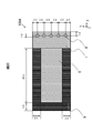
- FIG. 18 is a plan view of the circuit board 5 of the flow meter 100
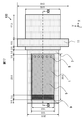
- FIG. 19 is a view of a cross section taken along the line XIX-XIX of FIG.
- the circuit board 5 and the housing 7, the press-fit terminal 8, the support 9, and the cover 10 were incorporated, and various other sensors were excluded from the model.
- FIG. 20 shows an analysis model of the flowmeter 100A in the second embodiment, in other words, the dimensions of the flowmeter 100A. Since the flow meter 100A is the same as the flow meter 100 except for the dimensions of the support, only the XIX-XIX sectional view of FIG. 17 corresponding to FIG. 19 of the flow meter 100 is shown.
- the circuit board 5 and the housing 7, the press-fit terminal 8, the support 9, and the cover 10 were incorporated, and various other sensors and the like were excluded from the model.
- the circuit board 5 is assumed to be a printed circuit board as an example, and has an elastic coefficient of 20.4 GPa, a Poisson's ratio of 0.2, and a density of 2000 kg / m 3 .
- a resin containing a glass filler is assumed as an example, and the modulus of elasticity is 8.1 GPa, the Poisson's ratio is 0.35, and the density is 1570 kg / m 3 .
- bronze is assumed as an example, and the modulus of elasticity is 115 GPa, Poisson's ratio is 0.32, and the density is 8830 kg / m 3 .
- the cover 10 is made of aluminum as an example, and has an elastic modulus of 71 GPa, a Poisson's ratio of 0.33, and a density of 2770 kg / m 3 .
- a low rigidity resin such as an elastomer is assumed as an example
- the Poisson's ratio is 0.499 equivalent to that of rubber
- the density is 1200 kg / m 3 .
- the elastic modulus was changed widely with 0.1, 1, 10, 100, 1000, 10000 MPa.
- the damping ratio required for frequency response analysis was 0.0135 as uniform for the structure.
- Load condition As a load condition, a cyclic load of 30 G was loaded in the Z direction of the flange portion 11 shown in FIG. In addition, as the contact condition, it was analyzed that the inner periphery of the through hole 6 of the circuit board 5 and the press fit terminal 8 were in a bonded state.
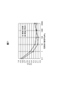
- FIG. 21 is a diagram showing an analysis result.
- the flow meter 100 and the flow meter 100A were analyzed by changing the elastic modulus of the support 9 to six ways of 0.1 MPa, 1 MPa, 10 MPa, 100 MPa, 1000 MPa, and 10000 MPa. Since the comparative example does not have the support 9 as described above, only one analysis was performed.
- the stress in the vicinity of the through hole 6 of the circuit board 5 is calculated in each analysis, and a value obtained by dividing the calculated value in the flow meter 100 and the flow meter 100A by the calculated value in the comparative example is shown in FIG.
- the calculation result of the flow meter 100 is a circle plot, and the label of “Embodiment 1” is attached.
- the calculation result of the flowmeter 100A is a triangular plot, and the label of “Embodiment 2” is attached.
- the stress ratio of the flow meter 100 and the flow meter 100A is about 0.8 to 0.9. That is, in this case, the difference from the comparative example without the support 9 is only 10% to 20%, and the effect of stress reduction is low.
- the stress ratio is decreased, that is, the effect of stress reduction is increased.
- the stress ratio does not necessarily decrease monotonically with the increase of the elastic modulus.
- the stress ratio became lower as the elastic modulus of the support 9 increased from 0.1 MPa to 10 MPa. It is considered that the support 9 is largely deformed in a region where the elastic modulus of the support 9 is extremely low such as 0.1 MPa, and the deformation of the circuit board 5 can not be sufficiently suppressed. On the other hand, there was not much difference in the stress reduction effect to such an extent that it slightly decreased even if it was raised above 10 MPa. From this result, in the structure of the flow meter 100 in the first embodiment, the elastic modulus of the support 9 is preferably 10 MPa or more.
- the stress ratio of the flow meter 100A shown by the triangular plot in FIG. 21 decreases as the elastic modulus of the support 9 increases from 0.1 MPa to 10 MPa.
- the elastic modulus of the support 9 exceeds 100 MPa, the stress ratio starts to increase. It is considered that when the elastic modulus of the support 9 is increased, the deformation of the cover 10 due to the vibration can not be absorbed by the deformation of the support 9 and transmitted to the circuit board 5 and the deformation suppressing effect of the circuit board 5 is reduced.
- the elastic modulus of the support 9 is preferably 10 MPa or more and 1000 MPa or less.
- the Young's modulus of the support 9 that is, the modulus of longitudinal elasticity, is preferably 10 MPa or more. By setting the Young's modulus of the support 9 to 10 MPa or more, the stress reduction effect of the support 9 can be enhanced.
Landscapes
- Physics & Mathematics (AREA)
- Fluid Mechanics (AREA)
- General Physics & Mathematics (AREA)
- Measuring Volume Flow (AREA)
Abstract
L'invention concerne un débitmètre qui comprend : un substrat en forme de plaque plate ; un boîtier qui contient le substrat et dont au moins une face, orientée dans une direction, est ouverte ; un couvercle qui recouvre le substrat et recouvre la face ouverte du boîtier ; un corps de support qui est en contact avec le couvercle et le substrat et porte le substrat ; et une section de fixation qui relie le substrat et le boîtier. Le substrat est divisé au niveau du centre longitudinal en une première région et une seconde région. Le corps de support est disposé dans la première région et la section de fixation est disposée dans la seconde région.
Priority Applications (3)
| Application Number | Priority Date | Filing Date | Title |
|---|---|---|---|
| US16/766,771 US11175166B2 (en) | 2017-11-27 | 2018-10-11 | Flow meter |
| DE112018005685.6T DE112018005685B4 (de) | 2017-11-27 | 2018-10-11 | Durchflussmesser |
| CN201880075012.7A CN111373226B (zh) | 2017-11-27 | 2018-10-11 | 流量计 |
Applications Claiming Priority (2)
| Application Number | Priority Date | Filing Date | Title |
|---|---|---|---|
| JP2017-227155 | 2017-11-27 | ||
| JP2017227155A JP6793107B2 (ja) | 2017-11-27 | 2017-11-27 | 流量計 |
Related Child Applications (1)
| Application Number | Title | Priority Date | Filing Date |
|---|---|---|---|
| US16/766,771 Continuation US11175166B2 (en) | 2017-11-27 | 2018-10-11 | Flow meter |
Publications (1)
| Publication Number | Publication Date |
|---|---|
| WO2019102737A1 true WO2019102737A1 (fr) | 2019-05-31 |
Family
ID=66630542
Family Applications (1)
| Application Number | Title | Priority Date | Filing Date |
|---|---|---|---|
| PCT/JP2018/037991 Ceased WO2019102737A1 (fr) | 2017-11-27 | 2018-10-11 | Débitmètre |
Country Status (5)
| Country | Link |
|---|---|
| US (1) | US11175166B2 (fr) |
| JP (1) | JP6793107B2 (fr) |
| CN (1) | CN111373226B (fr) |
| DE (1) | DE112018005685B4 (fr) |
| WO (1) | WO2019102737A1 (fr) |
Cited By (1)
| Publication number | Priority date | Publication date | Assignee | Title |
|---|---|---|---|---|
| US11415443B2 (en) * | 2019-12-03 | 2022-08-16 | Denso Corporation | Flow rate detector |
Families Citing this family (1)
| Publication number | Priority date | Publication date | Assignee | Title |
|---|---|---|---|---|
| JP7225062B2 (ja) * | 2019-08-29 | 2023-02-20 | 日立Astemo株式会社 | センサ装置 |
Citations (4)
| Publication number | Priority date | Publication date | Assignee | Title |
|---|---|---|---|---|
| US20040163462A1 (en) * | 2003-02-21 | 2004-08-26 | Visteon Global Technologies, Inc. | Slosh supressor and heat sink |
| JP2012052974A (ja) * | 2010-09-03 | 2012-03-15 | Hitachi Automotive Systems Ltd | 熱式流量センサ |
| JP2012234894A (ja) * | 2011-04-28 | 2012-11-29 | Mitsubishi Electric Corp | 電子回路収納ケース及びその製造方法 |
| JP2017190948A (ja) * | 2016-04-11 | 2017-10-19 | 日立オートモティブシステムズ株式会社 | 物理量検出装置 |
Family Cites Families (16)
| Publication number | Priority date | Publication date | Assignee | Title |
|---|---|---|---|---|
| JPH0748054B2 (ja) * | 1990-03-08 | 1995-05-24 | 株式会社日立製作所 | 発熱抵抗式空気流量計 |
| US7568399B2 (en) * | 2006-01-05 | 2009-08-04 | Integrated Sensing Systems, Inc. | Microfluidic device |
| US7823445B2 (en) * | 2007-12-07 | 2010-11-02 | Integrated Sensing Systems, Inc. | System and method of assessing a property of a flowing fluid |
| JP4956450B2 (ja) * | 2008-01-16 | 2012-06-20 | 株式会社東芝 | 電子機器の回路基板支持構造 |
| JP5208099B2 (ja) * | 2009-12-11 | 2013-06-12 | 日立オートモティブシステムズ株式会社 | 流量センサとその製造方法、及び流量センサモジュール |
| DE102010015813A1 (de) * | 2010-04-20 | 2011-10-20 | Krohne Messtechnik Gmbh | Sensoranordnung für ein kalorimetrisches Massedurchflussmessgerät |
| JP5183683B2 (ja) * | 2010-07-02 | 2013-04-17 | 三菱電機株式会社 | 流量測定装置 |
| JP5178806B2 (ja) | 2010-11-01 | 2013-04-10 | 三菱電機株式会社 | 流量測定装置 |
| US20140116137A1 (en) * | 2011-05-26 | 2014-05-01 | Nec Corporation | Acceleration sensor |
| JP5838749B2 (ja) * | 2011-11-16 | 2016-01-06 | セイコーエプソン株式会社 | 振動子、振動デバイスおよび電子機器 |
| JP5662382B2 (ja) * | 2012-06-15 | 2015-01-28 | 日立オートモティブシステムズ株式会社 | 熱式流量計 |
| JP6297392B2 (ja) * | 2014-04-08 | 2018-03-20 | アルプス電気株式会社 | 圧力検出装置 |
| JP2016090413A (ja) * | 2014-11-06 | 2016-05-23 | 日立オートモティブシステムズ株式会社 | 熱式空気流量計 |
| JP6475860B2 (ja) * | 2015-10-28 | 2019-02-27 | 日立オートモティブシステムズ株式会社 | 流量計 |
| JP6359594B2 (ja) | 2016-06-21 | 2018-07-18 | 本田技研工業株式会社 | 内燃機関の制御装置 |
| DE112018003485T5 (de) * | 2017-09-29 | 2020-03-19 | Hitachi Automotive Systems, Ltd. | Detektionsvorrichtung für physikalische Größen |
-
2017
- 2017-11-27 JP JP2017227155A patent/JP6793107B2/ja active Active
-
2018
- 2018-10-11 CN CN201880075012.7A patent/CN111373226B/zh active Active
- 2018-10-11 WO PCT/JP2018/037991 patent/WO2019102737A1/fr not_active Ceased
- 2018-10-11 DE DE112018005685.6T patent/DE112018005685B4/de active Active
- 2018-10-11 US US16/766,771 patent/US11175166B2/en active Active
Patent Citations (4)
| Publication number | Priority date | Publication date | Assignee | Title |
|---|---|---|---|---|
| US20040163462A1 (en) * | 2003-02-21 | 2004-08-26 | Visteon Global Technologies, Inc. | Slosh supressor and heat sink |
| JP2012052974A (ja) * | 2010-09-03 | 2012-03-15 | Hitachi Automotive Systems Ltd | 熱式流量センサ |
| JP2012234894A (ja) * | 2011-04-28 | 2012-11-29 | Mitsubishi Electric Corp | 電子回路収納ケース及びその製造方法 |
| JP2017190948A (ja) * | 2016-04-11 | 2017-10-19 | 日立オートモティブシステムズ株式会社 | 物理量検出装置 |
Cited By (1)
| Publication number | Priority date | Publication date | Assignee | Title |
|---|---|---|---|---|
| US11415443B2 (en) * | 2019-12-03 | 2022-08-16 | Denso Corporation | Flow rate detector |
Also Published As
| Publication number | Publication date |
|---|---|
| DE112018005685B4 (de) | 2024-07-04 |
| US11175166B2 (en) | 2021-11-16 |
| US20210003437A1 (en) | 2021-01-07 |
| DE112018005685T5 (de) | 2020-07-30 |
| JP6793107B2 (ja) | 2020-12-02 |
| CN111373226B (zh) | 2021-12-10 |
| JP2019095387A (ja) | 2019-06-20 |
| CN111373226A (zh) | 2020-07-03 |
Similar Documents
| Publication | Publication Date | Title |
|---|---|---|
| JP5511936B2 (ja) | 圧力測定モジュール | |
| US7216546B2 (en) | Pressure sensor having integrated temperature sensor | |
| JP4475160B2 (ja) | 電子装置の製造方法 | |
| CN104395722B (zh) | 压力检测装置 | |
| US20100242605A1 (en) | Sensor component | |
| CN102714031B (zh) | 具有阻尼装置的传感器 | |
| US7004033B2 (en) | Pressure sensor contained in casing | |
| JP6866121B2 (ja) | 半導体モジュール | |
| US7490520B2 (en) | Pressure sensor having improved arrangement of sensor chip for minimizing influence of external vibrations | |
| US20080236307A1 (en) | Sensor apparatus | |
| US20060137458A1 (en) | Acid-resistant pressure sensor | |
| WO2019102737A1 (fr) | Débitmètre | |
| JP2010071724A (ja) | 樹脂モールド半導体センサ及び製造方法 | |
| CN102577636B (zh) | 联接装置、具有联接装置的组件、用于制造具有联接装置的组件的方法 | |
| JP6802289B2 (ja) | 圧力検出装置 | |
| JP4742706B2 (ja) | 半導体装置及びその製造方法 | |
| JP5720450B2 (ja) | 圧力センサおよび圧力センサの取り付け構造 | |
| JP5994613B2 (ja) | 電子装置の取付構造体 | |
| WO2014136336A1 (fr) | Dispositif de capteur | |
| JP2007066575A (ja) | コネクタの実装構造及び実装方法 | |
| JP5039740B2 (ja) | 変速制御装置及び機電一体型電子制御装置 | |
| JP2006194682A (ja) | 温度センサ一体型圧力センサ装置 | |
| JP5521971B2 (ja) | センサ装置 | |
| JP5271852B2 (ja) | 電子部品付きパッケージ | |
| JP6658104B2 (ja) | 回路装置 |
Legal Events
| Date | Code | Title | Description |
|---|---|---|---|
| 121 | Ep: the epo has been informed by wipo that ep was designated in this application |
Ref document number: 18880387 Country of ref document: EP Kind code of ref document: A1 |
|
| 122 | Ep: pct application non-entry in european phase |
Ref document number: 18880387 Country of ref document: EP Kind code of ref document: A1 |