WO2019102752A1 - Actionneur, dispositif d'entraînement de lame, dispositif de capture d'image et équipement électronique - Google Patents
Actionneur, dispositif d'entraînement de lame, dispositif de capture d'image et équipement électronique Download PDFInfo
- Publication number
- WO2019102752A1 WO2019102752A1 PCT/JP2018/038768 JP2018038768W WO2019102752A1 WO 2019102752 A1 WO2019102752 A1 WO 2019102752A1 JP 2018038768 W JP2018038768 W JP 2018038768W WO 2019102752 A1 WO2019102752 A1 WO 2019102752A1
- Authority
- WO
- WIPO (PCT)
- Prior art keywords
- coil
- actuator
- magnet
- actuator according
- position detection
- Prior art date
- Legal status (The legal status is an assumption and is not a legal conclusion. Google has not performed a legal analysis and makes no representation as to the accuracy of the status listed.)
- Ceased
Links
Images










Classifications
-
- G—PHYSICS
- G03—PHOTOGRAPHY; CINEMATOGRAPHY; ANALOGOUS TECHNIQUES USING WAVES OTHER THAN OPTICAL WAVES; ELECTROGRAPHY; HOLOGRAPHY
- G03B—APPARATUS OR ARRANGEMENTS FOR TAKING PHOTOGRAPHS OR FOR PROJECTING OR VIEWING THEM; APPARATUS OR ARRANGEMENTS EMPLOYING ANALOGOUS TECHNIQUES USING WAVES OTHER THAN OPTICAL WAVES; ACCESSORIES THEREFOR
- G03B9/00—Exposure-making shutters; Diaphragms
- G03B9/08—Shutters
-
- H—ELECTRICITY
- H02—GENERATION; CONVERSION OR DISTRIBUTION OF ELECTRIC POWER
- H02K—DYNAMO-ELECTRIC MACHINES
- H02K33/00—Motors with reciprocating, oscillating or vibrating magnet, armature or coil system
- H02K33/16—Motors with reciprocating, oscillating or vibrating magnet, armature or coil system with polarised armatures moving in alternate directions by reversal or energisation of a single coil system
Definitions
- One embodiment of the present invention relates to a blade drive device, an imaging device, an actuator mounted on an electronic device, and the like.
- Electronic devices such as mobile phones and smart phones are equipped with various actuators, and the actuators operate based on user instructions and received information.
- an actuator is used in a shutter mechanism, an ND (Neutral Density) filter, a lens barrier, an automatic aperture mechanism, and the like in the imaging device.
- ND Neutral Density
- a coil is wound and a bobbin having a vibration space along a uniaxial direction inside, an outer frame covering the coil and extending the vibration space in a uniaxial direction, a magnet vibrating in the bobbin and a magnet in a uniaxial direction
- the outer periphery of the weight facing the inner surface of the outer frame comprising: a mover including a weight connected to one end side and vibrating in the outer frame; and an elastic member elastically supporting vibration in the axial direction of the mover. It discloses about the vibration actuator which fixed the resin layer to the surface and interposed the oil layer between the resin layer and the inner surface of the outer frame.
- the actuator as disclosed in Patent Document 1 in order to increase the drive stroke of the actuator, it is necessary to increase the number of turns of the coil in accordance with the drive stroke. If the number of turns is increased, the size of the coil may increase not only in the drive stroke direction but also in the direction perpendicular to the drive stroke in a plane perpendicular to the axial direction of the coil. In particular, in the case of an actuator incorporated in an electronic device, a smaller actuator is required even for an actuator having a relatively long operation stroke.
- a first coil (31) forming a first plane; Forming a second plane parallel to the first plane, and a second coil (32) disposed adjacent to the first coil with an insulating layer interposed therebetween; And a mover (5) having a magnet (53) disposed opposite to the first plane and the second plane, and moving along a driving direction.
- a wiring region extending in the driving direction of the first coil is formed to overlap with a wiring region extending in the driving direction of the second coil
- a wiring region extending in a direction perpendicular to the driving direction of the first coil is formed in a region different from a wiring region extending in a direction perpendicular to the driving direction of the second coil. It is an actuator.
- the first coil and the second coil by forming the first coil and the second coil in different layers, the first coil and the second coil can be arranged in an overlapping manner, and the wiring of the coil extending in the driving direction
- the area can be made substantially wide.
- the size of the entire coil including the first and second coils can be reduced while securing the wiring area of the coil in the drive direction, and the size can be reduced compared to the conventional actuator having the same operation stroke. .
- the core portion of the first coil (31) and the core portion of the second coil (32) have a common core portion (34) partially overlapping in plan view.
- control can be performed to move the mover in one direction with the direction of the current of the first coil and the direction of the current of the second coil being the same.
- the length of the common core portion (34) in the driving direction is smaller than the length of the magnet (53) in the driving direction.
- the actuator having the above configuration, even when the magnet of the mover moves near the center of the substrate coil, the magnet overlaps at least in part with the wiring region extending in the direction perpendicular to the driving direction, A Lorentz force is generated between the magnet and the coil. As a result, even when the magnet is positioned near the center of the substrate coil, a driving force is generated for the mover, so that the configuration can be appropriately operated.
- the first coil (31) and the second coil (32) are each spirally wound on an insulating substrate.
- the substrate coil can be made thinner.
- actuator preferably It further comprises a position detection sensor that detects the position of the mover.
- the actuator of the above configuration it is possible to detect the position of the mover with high accuracy. As a result, in the device on which the actuator is mounted, control such as precise position adjustment can be performed.
- the position detection sensor determines the position based on the detected magnetism.
- the actuator of the above configuration it is possible to detect the position of the mover using magnetism emitted from a magnet or a coil contained in the actuator.
- the position detection sensor determines the position by detecting magnetism from the magnet.
- the actuator having the above configuration, by using the magnet for generating the driving force in the actuator as an element for position detection, it is possible to achieve a relatively simple and inexpensive configuration without adding an element such as a magnet. Accurate position detection can be performed.
- the position detection sensor is disposed at the core of the first coil or at the core of the second coil.
- the actuator of the above configuration it is possible to suppress the influence of the magnetism emitted from the first coil and the second coil, and to enable position detection mainly based on the magnetism emitted from the magnet. As a result, it is possible to suppress the magnetic overlap and perform more accurate position detection. In addition, by utilizing the space at the core of the coil, the actuator can be made relatively compact.
- the position detection sensor is disposed on an axial extension of the core of the first coil and the core of the second coil.
- the actuator of the above configuration it is possible to suppress the influence of the magnetism emitted from the first coil and the second coil, and to enable position detection mainly based on the magnetism emitted from the magnet. As a result, it is possible to suppress the magnetic overlap and perform more accurate position detection.
- the size of the coil can be determined arbitrarily, so the design freedom regarding space is enhanced. It can be configured.
- the actuator according to the present invention can be configured to be able to detect the position with high accuracy.
- the position detection sensor optically determines the position.
- the position detection sensor can be disposed at an arbitrary position without being influenced by the arrangement of the magnet and the coil, so that the design with respect to space is enhanced. Can.
- One means of the present invention is Any of the above mentioned actuators, It is a blade drive device provided with the light quantity adjustment blade which operate
- the configuration can be further miniaturized.
- One means of the present invention is It includes an imaging device and an electronic device provided with any one of the above-described actuators.
- the configuration can be further miniaturized.
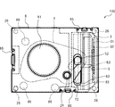
- FIG. 1 is an exploded perspective view of a blade driving device including the actuator of the embodiment.
- FIG. 2 is a plan view of the blade drive including the actuator of the embodiment in a state in which the shutter blade is open.
- FIG. 3 is a front view of the blade drive including the actuator of the embodiment in a state in which the shutter blade is open.
- FIG. 4 is a plan view of the blade drive including the actuator of the embodiment in a state in which the shutter blade is closed.
- FIG. 5 is a front view of the blade drive including the actuator according to the embodiment in a state in which the shutter blade is closed.
- 6 is a cross-sectional view taken along the line VI-VI of FIG.
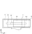
- FIG. 7 is a view schematically showing the arrangement of the substrate coil and the magnet in the Y direction view.
- FIG. 1 is an exploded perspective view of a blade driving device including the actuator of the embodiment.
- FIG. 2 is a plan view of the blade drive including the actuator of the embodiment in a state in which the shutter blade is
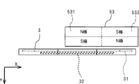
- FIG. 8 is a view schematically showing the arrangement of the substrate coil and the magnet in the Z direction view.
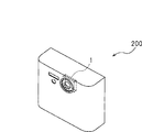
- FIG. 9 is a view showing an imaging apparatus having the actuator of the embodiment.
- FIG. 10 is a view showing an electronic device having the actuator of the embodiment.
- FIG. 11 is an exploded perspective view of a blade driving device including the actuator of the first modification.
- FIG. 12 is a plan view of the blade drive including the actuator of Modification 1 in a state in which the shutter blade is open.
- 13 is a cross-sectional view taken along line VII-VII of FIG.
- FIG. 14 is a view schematically showing the arrangement of the substrate coil and the magnet in the Y direction view in the actuator of the first modification.
- FIG. 15 is a view schematically showing the arrangement of the substrate coil and the magnet in the Z direction view in the actuator of the first modification.
- FIG. 16 is a view schematically showing the arrangement of the substrate coil and the magnet in the Y direction view in the actuator of the second modification.
- FIG. 17 is a view schematically showing the arrangement of the substrate coil and the magnet in the Z direction view in the actuator of the second modification.
- FIG. 18 is a cross-sectional view of a blade driving device including the actuator of the third modification.
- FIG. 19 is a view schematically showing the arrangement of the substrate coil and the magnet in the Y direction view in the actuator of the third modification.
- FIG. 20 is a view schematically showing the arrangement of the substrate coil and the magnet in the Z direction view in the actuator of the third modification.
- the actuator according to the present embodiment has a more miniaturized configuration as compared to an actuator using a single-layered coil by having the first coil and the second coil arranged in layers sandwiching the insulating layer. ing.
- the actuator of the present embodiment will be specifically described.
- FIG. 1 is an exploded perspective view of a blade driving device including the actuator of the present embodiment.
- FIGS. 2 to 3 are a plan view and a front view, respectively, of the blade drive including the actuator according to the present embodiment in a state in which the shutter blade is open.
- FIG.4 and FIG.5 is the top view and front view in the state which the shutter blade of the blade drive apparatus containing the actuator of this embodiment each closed.
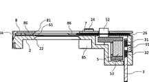
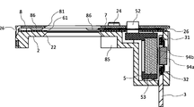
- 6 is a cross-sectional view taken along the line VI-VI of FIG.
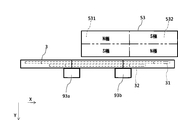
- FIG. 7 is a view schematically showing the arrangement of the substrate coil 3 and the magnet 53 in the Y direction view.
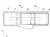
- FIG. 8 is a diagram schematically showing the arrangement of the substrate coil 3 and the magnet 53 in the Z direction view.
- the blade drive device 100 includes the actuator 1, the base member 2, the partition plate 6, the shutter blade 7 as a light amount adjustment blade, and the cover member 8. doing.
- the actuator 1 has a substrate coil 3 and a mover 5.
- the blade drive device 100 of the present embodiment will be described by taking a shutter mechanism of an imaging device as an example.
- the shutter blade 7 is a light amount adjustment blade that opens and closes the exposure opening to adjust the exposure time during which the imaging device (not shown) is exposed to external light.
- the substrate coil 3 has a first coil 31 and a second coil 32.
- the first coil 31 is wound on one plane to form a first plane.
- the second coil 32 is wound on a plane different from the first plane, forms a second plane parallel to the first plane, and sandwiches the insulating layer formed of an insulator in a layered manner. It is placed adjacent to 31.
- the first coil 31 and the second coil 32 may be formed by printed wiring in which metal wiring is spirally wound on the insulating substrate by printing.
- the substrate coil 3 also has a connecting portion 33 extending in the Z-axis direction.
- the connection portion 33 includes a wire for supplying power to the first coil 31 and the second coil 32, and the wire is covered with an insulator. Note that the first plane and the second plane do not indicate flat planes without thickness, but indicate configurations in which the wiring of the coil is arranged in a flat shape with a certain thickness.
- a part of the wiring region extending in the driving direction (X direction) of the first coil 31 corresponds to that of the second coil 32. It is formed to overlap with the wiring region extending in the driving direction. That is, a part of the wiring area extending in the driving direction of the first coil 31 and the wiring area extending in the driving direction of the second coil 32 overlap in the Y direction.
- the wiring area extending in the direction (Z direction) perpendicular to the driving direction of the first coil 31 is formed in an area different from the wiring area extending in the direction perpendicular to the driving direction of the second coil 32.
- the “wiring region” is a region in which one or more wires are formed, and in this case, a region in which a wire is formed by winding the coil. "Overlapping” is meant to be overlapped with the insulating layer interposed therebetween. “Formed in different areas” is not limited to the case where the wiring area of the first coil 31 and the wiring area of the second coil 32 extend in the Z direction in plan view and are formed in all different areas without overlapping. It includes the case where it is partially overlapped and partially formed differently. In the case where they are formed so as to be partially different from each other, the different wiring regions may have the effect of widening the moving range of the mover 5 described later.
- the core of the first coil 31 and the core of the second coil 32 have a common core 34 partially overlapping in a plan view from the Y direction.
- the movable core is disposed by arranging the common core portion 34 in the vicinity of the center of the first coil 31 and the second coil 32, and making the direction of the current flowing in the first coil 31 and the second coil 32 the same. Control to move 5 in one direction can be performed.
- the length of the common core portion 34 in the driving direction is smaller than the length of the magnet 53 in the driving direction.
- the mover 5 has a magnet holder 51 and a magnet 53.
- the magnet holder accommodates the magnet 53 and has an operating pin 52 for operating the shutter blade 7.
- the magnet 53 is a permanent magnet and is disposed to face the first flat surface of the first coil 31 and the second flat surface of the second coil 32, and moves along with the magnet holder 51 along the driving direction (X direction). .
- the magnet 53 has a first magnet 531 and a second magnet 532 aligned in the X direction.
- the arrangement of the magnets 53 with respect to the substrate coil 3 is such that the second magnet 532 extends in the direction (Z direction) perpendicular to the driving direction (X direction). It overlaps with the wiring area of the coil 31 and the second coil 32). Therefore, when the substrate coil 3 is energized, Lorentz force is generated in the second magnet 532 by the current flowing in the wiring area.
- the length of the magnet 53 in the X direction is larger than the length of the common core portion 34 in the X direction. Therefore, even when the magnet 53 is positioned near the center of the substrate coil 3, at least a part of the magnet 53 overlaps the wiring region extending in the direction perpendicular to the driving direction (Z direction). Lorentz force can be generated at least in part.
- the base member 2 has a housing portion 23 for housing the substrate coil 3 and the mover 5, and a support surface 21 having a base member opening 22 for exposing an imaging device (not shown). At the four corners of the base member 2, base-side spacers 26 described later are disposed.
- the base spacer 26 is a protrusion that defines a gap with the cover member 8.
- a fixing pin 24 which functions as a central axis of the shutter blade 7 which performs a rotation operation by reciprocating movement of the operation pin 52 is disposed.
- the partition plate 6 is disposed on the base member 2 (a position overlapping with the base member 2 in the Z direction).
- the partition plate 6 has a partition plate opening 61, a partition plate pin hole 62, a partition plate guide hole 63, and a spacer hole 64.
- the partition plate opening 61 is an opening for exposure similarly to the base member opening 22.
- the partition plate pin holes 62 are holes through which the fixing pins 24 are inserted.
- the partition plate guide hole 63 is opened corresponding to the movement range of the operating pin 52, and is inserted through the operating pin 52.
- the spacer hole 64 allows the base side spacer 26 to be inserted and defines the arrangement position of the partition plate 6.
- the shutter blade 7 is a light amount adjustment blade, and is disposed on the partition plate 6 and between the partition plate 6 and the cover member 8.
- the shutter blade 7 has a shutter blade pin hole 71 and a shutter blade guide hole 72.
- the shutter blade pin hole 71 is opened in the rotation shaft portion of the shutter blade 7 and the fixing pin 24 is inserted.
- the shutter blade guide hole 72 is a hole through which the operating pin 52 is inserted, and the movement of the operating pin 52 causes the shutter blade 7 to rotate about the fixing pin 24.
- the shutter blade 7 switches between the closed state of the shutter shown in FIGS. 2 and 3 and the open state of the shutter shown in FIGS. 4 and 5 by the actuating pin 52 moving with the mover 5.
- the cover member 8 is disposed on the partition plate 6 with the shutter blade 7 interposed therebetween.
- the cover member 8 has a cover member opening 81, a cover member pin hole 82, a cover member guide hole 83, a fastener 85, and a cover side spacer 86.
- the cover member opening 81 is an opening for exposure similarly to the base member opening 22.
- the cover member pin hole 82 is a hole through which the fixing pin 24 is inserted.
- the cover member guide hole 83 is opened corresponding to the movement range of the operating pin 52, and the operating pin 52 is inserted.
- the fasteners 85 secure the cover member 8 to the base member 2.
- the cover side spacer 86 is a projection that defines a gap between the cover member 8 and the partition plate 6. The cover member 8 secures a gap for disposing the shutter blade 7 by the cover side spacer 86 and the base side spacer 26.
- the actuator 1 when a driver circuit (not shown) causes current to flow to the first coil 31 and the second coil 32 of the substrate coil 3, Lorentz force is generated between the first coil 31 and the second coil 32 and the magnet 53. Occurs, and the mover 5 moves with the magnet 53. Further, in the blade driving device 100, the moving mover 5 operates the shutter blade 7 via the operation pin 52 to switch the shutter between the open state and the closed state.
- a driver circuit (not shown) causes current to flow to the first coil 31 and the second coil 32 of the substrate coil 3
- Lorentz force is generated between the first coil 31 and the second coil 32 and the magnet 53. Occurs, and the mover 5 moves with the magnet 53. Further, in the blade driving device 100, the moving mover 5 operates the shutter blade 7 via the operation pin 52 to switch the shutter between the open state and the closed state.
- the actuator 1 of the present embodiment by forming the first coil 31 and the second coil 32 in different layers, it is possible to overlap the wiring regions of the coils extending in the driving direction. Thereby, the size of the whole coil which consists of the 1st coil 31 and the 2nd coil 32 can be made small, and can be miniaturized compared with the conventional actuator which has the same operation stroke. Further, by providing the actuator 1, the blade drive device 100 of the present embodiment can be made smaller than the configuration provided with the conventional actuator.
- the substrate coil 3 since the substrate coil 3 has the common core 34, the direction of the current of the first coil 31 and the direction of the current of the second coil 32 are the same, and the mover 5 is moved in one direction. Control can be performed.
- the magnet 53 of the mover 5 even when the magnet 53 of the mover 5 is moved to the vicinity of the center of the substrate coil 3, the magnet 53 has at least a part of the wiring region extending in the direction perpendicular to the driving direction. In order to generate Lorentz force, the mover 5 can be operated.
- first coil 31 and the second coil 32 have a flat plate shape which is thinned by laminating an insulating substrate on which the first coil 31 is wired and an insulating substrate on which the second coil 32 is wired.
- FIG. 9 is a view showing an imaging device 200 having the actuator 1 of the present embodiment.
- the imaging device 200 is, for example, an imaging device 200 mounted on a mobile phone, a smartphone, a tablet terminal, or another electronic device.
- the actuator 1 of the imaging device 200 can be applied to, for example, a shutter mechanism, an ND filter, a lens barrier, an automatic aperture mechanism, and the like.
- the imaging device 200 can be made smaller than the configuration provided with the conventional actuator by including the actuator 1 of the present embodiment.
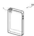
- FIG. 10 is a view showing an electronic device 300 having the actuator 1 of the present embodiment.
- the electronic device 300 is an example of a mobile phone, a smartphone, a tablet terminal, and other electronic devices.
- the actuator 1 of the electronic device 300 can be applied to, for example, a drive portion of a camera mounted on the electronic device 300.
- the electronic device 300 can be made smaller than the configuration provided with the conventional actuator by including the actuator 1 of the present embodiment.
- FIG. 11 to 15 are diagrams showing the configuration of Modification 1 of the embodiment.
- FIG. 11 is an exploded perspective view of the actuator, corresponding to FIG. 1 of the embodiment.
- FIG. 12 is a plan view of the actuator in the state in which the shutter blade is open, and corresponds to FIG. 2 of the embodiment.
- 13 is a cross-sectional view taken along the line VII-VII of FIG. 12, and corresponds to FIG. 6 of the embodiment.
- FIG. 14 is a plan view schematically showing the arrangement of the substrate coil 3 and the magnet 53 of the actuator in the Y direction view, and corresponds to FIG. 7 of the embodiment.
- FIG. 15 is a plan view schematically showing the arrangement of the substrate coil 3 and the magnet 53 of the actuator in the Z direction view, and corresponds to FIG. 8 of the embodiment.
- the blade drive device 100 of the present modification includes the actuator 1, the base member 2, the partition plate 6, the shutter blade 7 as a light amount adjustment blade, and the cover member 8, and further a hole.
- a sensor 91 is provided.
- the hall sensor 91 is one specific example of the "position detection sensor" in the present invention.
- the Hall sensor 91 detects the magnetic field and outputs the detected magnetic field to detect the position of the magnet disposed in the periphery.
- the Hall sensor 91 may function as a position sensor by being used together with other semiconductor devices or comparators, but in the present specification, a configuration including elements such as such other semiconductor devices or comparators It is called a hall sensor.
- a recess 92 is formed on the end face of the base member 2 in the Y-axis + direction (see FIG. 11).
- a hole sensor 91 is accommodated in the recess 92 of the base member 2 and fixed to the substrate coil 3 by soldering or the like.
- the recess 92 in which the hall sensor 91 is housed is disposed together with the magnet 53 so as to sandwich the substrate coil 3 (refer mainly to FIGS. 13 to 15).
- the recess 92 is disposed at a position on the extension of the Y-axis direction (axial direction) of the core of the first coil 31 and the core of the second coil 32.
- the Hall sensor 91 detects the position of the magnet 53 relative to the base member 2 by mainly detecting the strength of the magnetic field emitted from the magnet 53. Since the magnet 53 is fixed to the mover 5, the position of the mover 5 relative to the base member 2 can be detected.
- the Hall sensor 91 may be fixed to the substrate coil 3 of the actuator 1 instead of being fixed to the base member 2. Further, the base member 2 and the substrate coil 3 may be fixed via the hall sensor 91. In this case, the hall sensor 91 is fixed to both the base member 2 and the substrate coil 3. Even with such a configuration, the position of the mover 5 with respect to the substrate coil 3 can be detected.
- the base member 2 may have a lead frame for supplying power to the hall sensor 91, and the power may be supplied to the hall sensor 91 attached to the base member 2 through the lead frame.
- FIG. 16 and FIG. 17 are diagrams showing the configuration of the modification 2 of the embodiment.
- FIG. 16 is a plan view schematically showing the arrangement of the substrate coil 3 and the magnet 53 of the actuator in the Y direction view, and corresponds to FIG. 7 of the embodiment.
- FIG. 17 is a plan view schematically showing the arrangement of the substrate coil 3 and the magnet 53 of the actuator in the Z direction view, and corresponds to FIG. 8 of the embodiment.
- the blade driving device 100 of the present modification includes the actuator 1, the base member 2, the partition plate 6, the shutter blade 7 which is a light amount adjusting blade, and the cover member 8.
- Hall sensors 93a and 93b are disposed in the recess 92 of the base member 2 and fixed to the substrate coil 3 by soldering or the like, as in the first modification.
- Hall sensors 93a and 93b are arranged in alignment in the X direction, which is the moving direction of mover 5. More specifically, the Hall sensors 93a and 93b are respectively disposed in the vicinity of the end of the core of the second coil 32 in the X direction.
- Hall sensors 93a and 93b are one example of the "position detection sensor" of the present invention.
- FIG. 18 to FIG. 20 are diagrams showing the configuration of Modification 3 of the embodiment.
- FIG. 18 is a cross-sectional view of the blade drive device 100 of the present modification, corresponding to FIG. 6 of the embodiment.
- FIG. 19 is a plan view schematically showing the arrangement of the substrate coil 3 and the magnet 53 of the actuator in the Y direction view, corresponding to FIG. 7 of the embodiment.
- FIG. 20 is a plan view schematically showing the arrangement of the substrate coil 3 and the magnet 53 of the actuator in the Z direction view, and corresponds to FIG. 8 of the embodiment.
- the blade drive device 100 of the present modification includes the actuator 1, the base member 2, the partition plate 6, the shutter blade 7 which is a light amount adjustment blade, and the cover member 8. It has a reflector 94a and a position detection tape 94b.
- the photo reflector 94 a and the position detection tape 94 b are optical sensors that optically detect the position, and are one specific example of the “position detection sensor” in the present invention.
- the photo reflector 94 a is disposed at the core of the first coil 31 and the second coil 32 in the substrate coil 3.
- the position detection tape 94b is located on the surface of the magnet 53 of the mover 5, and is attached to the magnet 53 with an adhesive, for example.
- On the position detection tape 94b two types of band-like patterns having different light reflectances are engraved at equal intervals.
- the photo reflector 94a has four terminals, a light emitting unit 94a1 and a light receiving unit 94a2.
- the photo reflector 94a emits light from the light emitting unit 94a1, the light reflected by the position detection tape 94b is detected by the light receiving unit 94a2, and the intensity of the detected light or the position of the photo reflector 94a according to the change in intensity
- the relative position with the detection tape 94b is optically detected. More specifically, the photo reflector 94a detects the position of the position detection tape 94b with respect to the light receiving portion 94a2 of the photo reflector 94a by counting the change in the reflected light detected by the light receiving portion 94a2.
- the position of the magnet 53 (the mover 5) on which the position detection tape 94b is disposed can be detected with respect to the substrate coil 3 on which the photo reflector 94a is disposed.
- the position detection sensor for detecting the position of the mover 5 is provided, so that the position of the mover 5 can be detected with high accuracy.
- control such as precise position adjustment can be performed.
- the position of the blade can be adjusted more precisely.
- the position detection is performed based on the magnetism detected by the Hall sensor 91 or 93a and 93b. Thereby, it becomes possible to detect the position of the mover 5 using the magnetism emitted from the magnet 53 or the substrate coil 3 included in the actuator 1.
- the magnetism from the magnet 53 for generating the driving force is detected by the hall sensor 91 or 93a and 93b without adding the configuration for generating the magnetism.
- the position is detected by. Therefore, highly accurate position detection can be performed with a relatively simple and inexpensive configuration without adding an element such as a magnet.
- the Hall sensor 91 or 93 a and 93 b may be disposed at the core of the first coil 31 or at the core of the second coil 32.
- the influence of the magnetism emitted from the first coil 31 and the second coil 32 can be suppressed, and position detection based on the magnetism emitted mainly from the magnet 53 can be enabled.
- the actuator 1 can be configured to be relatively small.
- the Hall sensor 91 or 93a and 93b is disposed on the extension of the core of the first coil 31 and the core of the second coil 32 in the axial direction (Y direction). ing.
- the influence of the magnetism emitted from the first coil 31 and the second coil 32 can be suppressed, and position detection based on the magnetism emitted mainly from the magnet 53 can be enabled.
- the size of the substrate coil 3 can be arbitrarily determined regardless of the size of the Hall sensor. Can be configured with a high degree of design freedom.
- the position can be accurately detected. It can be done.
- the Hall sensors 93a and 93b are arranged along the moving direction, so that the position can be detected accurately in a long moving range.
- the position detection sensor is configured to have the photo reflector 94a as the optical sensor and the position detection tape 94b, it is optional without being influenced by the arrangement of the magnet 53 and the substrate coil 3.
- the position detection sensor can be easily arranged at the location of This makes it possible to increase the degree of freedom in space design.
- the photo reflector 94 a and the position detection tape 94 b of the third modification are an example of an optical sensor, and the present invention is not limited to such an optical sensor.
- the optical sensor for example, various configurations such as an optical encoder or a photo interrupter can be adopted.
- the shutter blade 7 is mentioned as an example of the light amount adjusting blade, but the light amount adjusting blade is not limited to the shutter blade, and includes an aperture blade and the like. That is, the light amount adjustment blade includes a member that adjusts the amount (light amount) of light emitted to the imaging device, and takes time for which the imaging device is exposed to light.
- the light amount adjustment blade includes an ND filter of uniform density, a gradation ND filter, an infrared cut filter, and the like having the function of adjusting the transmitted light amount and adjusting the wavelength of the transmitted light. In this case, the light amount adjustment blade is switched between the state in which the entire exposure opening is covered and the state in which the light amount adjustment blade is open.
- an actuator can be applied to devices other than a blade drive.
- the actuator of the present invention further includes various configurations of the conventional actuator.
- the actuator of the present invention is suitably used for a blade drive device, an imaging device and an electronic device.
- cover member opening 82 ... cover member pin hole 83 ... cover member guide hole 85 ... fastener 86 ... cover side spacer 91, 93a, 93b ... Hall sensor 92: Recess 94a: Photo reflector 94b: Position detection tape 100: Blade drive device 200: Imaging device 300: Electronic device
Landscapes
- Engineering & Computer Science (AREA)
- Power Engineering (AREA)
- Physics & Mathematics (AREA)
- General Physics & Mathematics (AREA)
- Shutters For Cameras (AREA)
- Reciprocating, Oscillating Or Vibrating Motors (AREA)
Abstract
La présente invention concerne un actionneur qui est équipé : d'une première bobine présentant une première surface plate formée au niveau d'une extrémité axiale de cette dernière ; d'une seconde bobine qui présente une seconde surface plate formée au niveau d'une extrémité axiale de cette dernière de façon à être parallèle à la première surface plate, et qui est disposée adjacente à la première bobine, une couche isolante étant interposée entre lesdites bobines ; et un dispositif de déplacement qui possède un aimant disposé en face des première et seconde surfaces plates et qui se déplace dans une direction d'excitation. Dans une vue en plan axial, une partie d'une région de câblage qui s'étend dans la direction d'excitation de la première bobine est formée de manière à chevaucher une région de câblage qui s'étend dans la direction d'excitation de la seconde bobine, et une région de câblage qui s'étend dans la direction perpendiculaire à la direction d'excitation de la première bobine est formée dans une région différente d'une région de câblage qui s'étend dans la direction perpendiculaire à la direction d'excitation de la seconde bobine.
Priority Applications (1)
| Application Number | Priority Date | Filing Date | Title |
|---|---|---|---|
| CN201880074745.9A CN111357178B (zh) | 2017-11-24 | 2018-10-18 | 致动器、叶片驱动装置、摄像装置以及电子设备 |
Applications Claiming Priority (4)
| Application Number | Priority Date | Filing Date | Title |
|---|---|---|---|
| JP2017-225834 | 2017-11-24 | ||
| JP2017225834 | 2017-11-24 | ||
| JP2018-032189 | 2018-02-26 | ||
| JP2018032189A JP7113631B2 (ja) | 2017-11-24 | 2018-02-26 | アクチュエータ、羽根駆動装置、撮像装置及び電子機器 |
Publications (1)
| Publication Number | Publication Date |
|---|---|
| WO2019102752A1 true WO2019102752A1 (fr) | 2019-05-31 |
Family
ID=66631452
Family Applications (1)
| Application Number | Title | Priority Date | Filing Date |
|---|---|---|---|
| PCT/JP2018/038768 Ceased WO2019102752A1 (fr) | 2017-11-24 | 2018-10-18 | Actionneur, dispositif d'entraînement de lame, dispositif de capture d'image et équipement électronique |
Country Status (1)
| Country | Link |
|---|---|
| WO (1) | WO2019102752A1 (fr) |
Citations (3)
| Publication number | Priority date | Publication date | Assignee | Title |
|---|---|---|---|---|
| JPH10117470A (ja) * | 1996-10-11 | 1998-05-06 | Tdk Corp | 面移動アクチュエータ |
| JP2007020264A (ja) * | 2005-07-06 | 2007-01-25 | Seiko Epson Corp | 電磁駆動力を利用したアクチュエータの制御 |
| JP2010099642A (ja) * | 2008-09-29 | 2010-05-06 | Sanyo Electric Co Ltd | 振動モータおよびそれを用いた携帯端末装置 |
-
2018
- 2018-10-18 WO PCT/JP2018/038768 patent/WO2019102752A1/fr not_active Ceased
Patent Citations (3)
| Publication number | Priority date | Publication date | Assignee | Title |
|---|---|---|---|---|
| JPH10117470A (ja) * | 1996-10-11 | 1998-05-06 | Tdk Corp | 面移動アクチュエータ |
| JP2007020264A (ja) * | 2005-07-06 | 2007-01-25 | Seiko Epson Corp | 電磁駆動力を利用したアクチュエータの制御 |
| JP2010099642A (ja) * | 2008-09-29 | 2010-05-06 | Sanyo Electric Co Ltd | 振動モータおよびそれを用いた携帯端末装置 |
Similar Documents
| Publication | Publication Date | Title |
|---|---|---|
| US12372758B2 (en) | Rotational ball-guided voice coil motor | |
| JP5963641B2 (ja) | レンズ駆動装置 | |
| JP5765361B2 (ja) | レンズ保持装置 | |
| CN117075297A (zh) | 光学组件驱动机构 | |
| US8090247B2 (en) | Vibration reduction unit, lens barrel and camera | |
| JP6679143B2 (ja) | レンズ駆動装置 | |
| US11971276B2 (en) | Camera device | |
| US11561360B2 (en) | Optical system | |
| JP5612390B2 (ja) | 光学ユニット | |
| WO2018051729A1 (fr) | Dispositif de commande de lentille et module de caméra utilisant ledit dispositif de commande de lentille | |
| JP7113631B2 (ja) | アクチュエータ、羽根駆動装置、撮像装置及び電子機器 | |
| JP6006044B2 (ja) | レンズ駆動装置 | |
| JP6122352B2 (ja) | 撮影用光学装置 | |
| WO2019102752A1 (fr) | Actionneur, dispositif d'entraînement de lame, dispositif de capture d'image et équipement électronique | |
| JP7175603B2 (ja) | アクチュエータ、レンズ駆動モータ及び電子機器 | |
| JP5900682B1 (ja) | 1軸回転アクチュエーター | |
| JP6948139B2 (ja) | モバイル用電磁駆動装置 | |
| JP6561878B2 (ja) | 1軸回転アクチュエーター | |
| WO2018139197A1 (fr) | Actionneur électromagnétique | |
| JP6605531B2 (ja) | モバイル用電磁駆動装置 | |
| IL259031A (en) | Rotary coil motor based on ball bearing |
Legal Events
| Date | Code | Title | Description |
|---|---|---|---|
| 121 | Ep: the epo has been informed by wipo that ep was designated in this application |
Ref document number: 18880917 Country of ref document: EP Kind code of ref document: A1 |
|
| NENP | Non-entry into the national phase |
Ref country code: DE |
|
| 122 | Ep: pct application non-entry in european phase |
Ref document number: 18880917 Country of ref document: EP Kind code of ref document: A1 |