WO2019102760A1 - Dispositif de génération d'énergie solaire à concentration - Google Patents
Dispositif de génération d'énergie solaire à concentration Download PDFInfo
- Publication number
- WO2019102760A1 WO2019102760A1 PCT/JP2018/039138 JP2018039138W WO2019102760A1 WO 2019102760 A1 WO2019102760 A1 WO 2019102760A1 JP 2018039138 W JP2018039138 W JP 2018039138W WO 2019102760 A1 WO2019102760 A1 WO 2019102760A1
- Authority
- WO
- WIPO (PCT)
- Prior art keywords
- power
- panel
- control
- concentrating solar
- connector
- Prior art date
- Legal status (The legal status is an assumption and is not a legal conclusion. Google has not performed a legal analysis and makes no representation as to the accuracy of the status listed.)
- Ceased
Links
Images


Classifications
-
- H—ELECTRICITY
- H02—GENERATION; CONVERSION OR DISTRIBUTION OF ELECTRIC POWER
- H02G—INSTALLATION OF ELECTRIC CABLES OR LINES, OR OF COMBINED OPTICAL AND ELECTRIC CABLES OR LINES
- H02G3/00—Installations of electric cables or lines or protective tubing therefor in or on buildings, equivalent structures or vehicles
- H02G3/02—Details
- H02G3/04—Protective tubing or conduits, e.g. cable ladders or cable troughs
- H02G3/0462—Tubings, i.e. having a closed section
- H02G3/0481—Tubings, i.e. having a closed section with a circular cross-section
-
- H—ELECTRICITY
- H02—GENERATION; CONVERSION OR DISTRIBUTION OF ELECTRIC POWER
- H02G—INSTALLATION OF ELECTRIC CABLES OR LINES, OR OF COMBINED OPTICAL AND ELECTRIC CABLES OR LINES
- H02G3/00—Installations of electric cables or lines or protective tubing therefor in or on buildings, equivalent structures or vehicles
- H02G3/30—Installations of cables or lines on walls, floors or ceilings
- H02G3/34—Installations of cables or lines on walls, floors or ceilings using separate protective tubing
-
- H—ELECTRICITY
- H02—GENERATION; CONVERSION OR DISTRIBUTION OF ELECTRIC POWER
- H02S—GENERATION OF ELECTRIC POWER BY CONVERSION OF INFRARED RADIATION, VISIBLE LIGHT OR ULTRAVIOLET LIGHT, e.g. USING PHOTOVOLTAIC [PV] MODULES
- H02S20/00—Supporting structures for PV modules
- H02S20/10—Supporting structures directly fixed to the ground
-
- H—ELECTRICITY
- H02—GENERATION; CONVERSION OR DISTRIBUTION OF ELECTRIC POWER
- H02S—GENERATION OF ELECTRIC POWER BY CONVERSION OF INFRARED RADIATION, VISIBLE LIGHT OR ULTRAVIOLET LIGHT, e.g. USING PHOTOVOLTAIC [PV] MODULES
- H02S20/00—Supporting structures for PV modules
- H02S20/30—Supporting structures being movable or adjustable, e.g. for angle adjustment
- H02S20/32—Supporting structures being movable or adjustable, e.g. for angle adjustment specially adapted for solar tracking
-
- H—ELECTRICITY
- H02—GENERATION; CONVERSION OR DISTRIBUTION OF ELECTRIC POWER
- H02S—GENERATION OF ELECTRIC POWER BY CONVERSION OF INFRARED RADIATION, VISIBLE LIGHT OR ULTRAVIOLET LIGHT, e.g. USING PHOTOVOLTAIC [PV] MODULES
- H02S40/00—Components or accessories in combination with PV modules, not provided for in groups H02S10/00 - H02S30/00
- H02S40/30—Electrical components
- H02S40/34—Electrical components comprising specially adapted electrical connection means to be structurally associated with the PV module, e.g. junction boxes
-
- Y—GENERAL TAGGING OF NEW TECHNOLOGICAL DEVELOPMENTS; GENERAL TAGGING OF CROSS-SECTIONAL TECHNOLOGIES SPANNING OVER SEVERAL SECTIONS OF THE IPC; TECHNICAL SUBJECTS COVERED BY FORMER USPC CROSS-REFERENCE ART COLLECTIONS [XRACs] AND DIGESTS
- Y02—TECHNOLOGIES OR APPLICATIONS FOR MITIGATION OR ADAPTATION AGAINST CLIMATE CHANGE
- Y02E—REDUCTION OF GREENHOUSE GAS [GHG] EMISSIONS, RELATED TO ENERGY GENERATION, TRANSMISSION OR DISTRIBUTION
- Y02E10/00—Energy generation through renewable energy sources
- Y02E10/50—Photovoltaic [PV] energy
Definitions
- the present disclosure relates to a concentrator photovoltaic device.
- This application claims the priority based on Japanese Patent Application No. 2017-225981 filed on Nov. 24, 2017. The entire contents of the description of the Japanese patent application are incorporated herein by reference.
- Patent Document 1 describes a cable wiring structure of a solar power generation system disposed on a roof. In the solar power generation system, power generated by the solar power generation module is sent to the indoor inverter through the cable wiring.
- a concentrating solar power generation apparatus includes a concentrating solar power generation panel and a wire harness for electric power.
- the wire harness for electric power is connected to the concentrating solar power generation panel.
- the power wiring harness includes a plurality of power cables capable of extracting power generated by the concentrating solar power generation panel, and a power insulating tube for bundling the plurality of power cables.
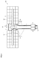
- FIG. 1 is a front schematic diagram which shows the structure of the condensing solar power generation device which concerns on this embodiment.
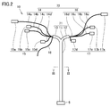
- FIG. 2 is a front schematic diagram which shows the structure of the wire harness for electric power of the condensing solar power generation device which concerns on this embodiment.
- FIG. 3 is a schematic cross-sectional view taken along the line III-III in FIG.
- FIG. 4 is a schematic diagram which shows the structure of the edge part of the insulation tube for electric power of the condensing solar power generation device which concerns on this embodiment.
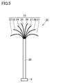
- FIG. 5 is a front schematic diagram which shows the structure of the wire harness for control of the condensing solar power generation device which concerns on this embodiment.
- FIG. 1 is a front schematic diagram which shows the structure of the condensing solar power generation device which concerns on this embodiment.
- FIG. 2 is a front schematic diagram which shows the structure of the wire harness for electric power of the condensing solar power generation device which concerns on this embodiment.
- FIG. 3 is a schematic cross-sectional view taken along
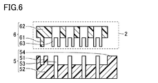
- FIG. 6 is a partial cross-sectional schematic view showing the configuration of the power cable side connector and the connection box side connector of the concentrating solar power generation apparatus according to this embodiment.
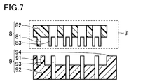
- FIG. 7 is a partial cross-sectional schematic view showing the configuration of the control cable side connector and the control box side connector of the concentrating solar power generation device according to the present embodiment.
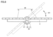
- FIG. 8 is a schematic top view showing a first state of the concentrating solar power generation device according to the present embodiment.
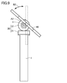
- FIG. 9 is a schematic side view showing a second state of the concentrating solar power generation device according to the present embodiment.
- One aspect of the present disclosure is made to solve the problems as described above, and an object of the present disclosure is to provide a light collecting type capable of improving the insulation performance of a power cable while improving the efficiency of attaching the power cable. It is providing a solar power generation device.
- a concentrating solar power generation apparatus 100 includes a concentrating solar power generation panel 40 and a wire harness 10 for electric power.
- the power wiring harness 10 is connected to the concentrating solar power generation panel 40.
- the power wiring harness 10 includes a plurality of power cables 72 capable of extracting power generated by the concentrating solar power generation panel 40 and a power insulating tube 71 for bundling the plurality of power cables 72.
- the insulation performance of the power cables 72 can be enhanced.
- the reliability of the power cable 72 can be improved.
- by bundling the plurality of power cables 72 with the power insulating tube 71 and forming a harness it is possible to improve the mounting work efficiency of the power cables 72.
- the concentrating solar power generation device 100 includes a driving unit 30 capable of driving the concentrating solar power generation panel 40 and the control wire harness 20 connected to the driving unit 30. You may provide further.
- the control wire harness 20 may include a plurality of control cables 73 connected to the drive unit 30 and a control insulating tube 29 bundling the plurality of control cables 73.
- the voltage applied to each of the plurality of power cables 72 may be higher than the voltage applied to each of the plurality of control cables 73.
- the concentrating solar power generation device 100 according to (2) may further include a gantry 1 that supports the drive unit 30.
- Each of the power wire harness 10 and the control wire harness 20 may be provided along the extending direction of the gantry 1. Thereby, when the concentrating solar power generation panel 40 rotates, interference of each of the power wire harness 10 and the control wire harness 20 with the condensing solar power generation panel 40 can be prevented.
- the concentrating solar power generation device 100 according to (3) may further include the connection box 2 attached to the gantry 1.
- the junction box 2 may include the first connector 6.
- the power wire harness 10 may include a second connector 5 connectable to the first connector 6. Thereby, the attachment efficiency of the wire harness 10 for electric power with respect to the connection box 2 can be improved.
- the concentrating solar power generation panel 40 comprises a first panel portion 41 and a second panel portion 41 provided separately from each other.
- a two panel unit 42 may be included.
- the power wire harness 10 may include a first panel connector 15 connected to the first panel 41 and a second panel connector 17 connected to the second panel 42.
- the shape of the first panel connector 15 may be different from the shape of the second panel connector 17.
- the mounting work efficiency of the power cable 72 can be further improved.
- the plurality of power cables 72 includes the plurality of first power cable units 14 connected to the first panel unit 41, and the second panel unit 42. And a plurality of second power cable sections 16 connected thereto.
- the power insulating tube 71 does not surround the first region 11 surrounding both of the plurality of first power cable portions 14 and the plurality of second power cable portions 16 and the plurality of first power cable portions 14 and includes the plurality of second regions. And the second region 12 surrounding the power cable portion 16.
- the plurality of power cables 72 are branched into the plurality of first power cable portions 14 connected to the first panel portion 41 and the plurality of second power cable portions 16 connected to the second panel portion 42. be able to.
- the power insulating tube 71 may be a corrugated tube. Since the corrugated tube has high flexibility, the degree of freedom of wiring can be increased.
- the power insulating tube 71 may be made of a material containing nylon 12. Nylon 12 is weather resistant to ultraviolet light. Therefore, even when the concentrating solar power generation device 100 is installed in a place with a large amount of solar radiation, such as a desert, the power insulating tube 71 can be prevented from deteriorating.
- the concentrating solar power generation apparatus 100 includes a concentrating solar power generation panel 40, a power wire harness 10, a control wire harness 20, and a drive unit 30. And a mount 1, a shaft 4, a connection box 2, and a control box 3 are mainly included.
- the concentrating solar power generation panel 40 has, for example, a first panel unit 41 and a second panel unit 42. Each of the first panel portion 41 and the second panel portion 42 is attached to the shaft 4. The first panel portion 41 and the second panel portion 42 are provided separately from each other.
- Each of the 1st panel part 41 and the 2nd panel part 42 has a plurality of photovoltaic power generation modules (not shown).
- the power generation capacity of each of the plurality of photovoltaic modules is, for example, 150 watts.
- the total power generation capacity of the concentrating solar power generation device 100 according to the present embodiment may be, for example, 30 kilowatts or more.
- the power wiring harness 10 is for taking out the power generated by the concentrating solar power generation panel 40 to the outside.
- the power wiring harness 10 is connected to the concentrating solar power generation panel 40.
- the driving unit 30 can arbitrarily change the direction of the concentrating solar power generation panel 40.
- the drive unit 30 has, for example, an azimuth drive unit 31 and an elevation drive unit 32.
- the gantry 1 supports a drive unit 30. Specifically, the azimuth angle drive unit 31 is supported by the gantry 1.
- the azimuth angle drive unit 31 is disposed, for example, on the gantry 1.
- the elevation drive 32 is attached to the azimuth drive 31.
- Elevation angle drive unit 32 is arranged, for example, on azimuth angle drive unit 31.
- the shaft 4 is attached to the elevation drive 32.
- the shaft 4 is rotatable along with the drive of the elevation drive 32.
- the control wire harness 20 is for controlling the drive unit 30.
- the control wire harness 20 is connected to the drive unit 30. Specifically, the control wire harness 20 is connected to each of the azimuth drive unit 31 and the elevation drive unit 32.
- the junction box 2 is attached to, for example, a gantry 1.
- the power wire harness 10 is connected to the connection box 2.
- Control box 3 is attached to, for example, mount 1.
- the control box 3 is adjacent to the connection box 2 in the circumferential direction of the gantry 1, for example.
- the control wire harness 20 is connected to the control box 3.
- the gantry 1 has, for example, a cylindrical shape.
- Each of connection box 2 and control box 3 is attached to, for example, the outer peripheral surface of gantry 1.
- Each of the power wire harness 10 and the control wire harness 20 is provided, for example, along the extending direction (longitudinal direction) of the gantry 1.
- the power wire harness 10 has a portion extending from the azimuth drive unit 31 toward the connection box 2. Specifically, the power wire harness 10 extends from the azimuth drive unit 31 toward the bottom surface 1 a of the gantry 1, extends between the connection box 2 and the bottom surface 1 a and extends toward the connection box 2. doing.
- the control wire harness 20 has a portion extending from the azimuth drive 31 to the control box 3. Specifically, the control wire harness 20 extends from the azimuth drive unit 31 toward the bottom surface 1 a of the gantry 1, folds back between the control box 3 and the bottom surface 1 a, and extends toward the control box 3. doing.
- Each of the power wire harness 10 and the control wire harness 20 may be attached to, for example, the outer peripheral surface of the gantry 1.
- the power wire harness 10 has, for example, a plurality of power cables 72 and a power insulating tube 71.
- the plurality of power cables 72 can extract power generated by the concentrating solar power generation panel 40.
- the power insulating tube 71 bundles a plurality of power cables 72.
- the plurality of power cables 72 includes, for example, a plurality of first power cable portions 14, a plurality of second power cable portions 16, and a ground wire 18.
- Each of the plurality of first power cable units 14 is connected to the first panel unit 41.
- Each of the plurality of second power cable units 16 is connected to the second panel unit 42.
- Power insulating tube 71 has, for example, a first area 11, a second area 12, and a third area 13.
- the first region 11 surrounds both the plurality of first power cable portions 14 and the plurality of second power cable portions 16.
- the second region 12 does not surround the plurality of first power cable portions 14 and surrounds the plurality of second power cable portions 16.
- the third region 13 surrounds the plurality of first power cable portions 14 and does not surround the plurality of second power cable portions 16.
- Each of the first area 11 and the third area 13 may further surround the ground wire 18.
- the length of the ground wiring 18 exposed from the third region 13 is, for example, 1 m.
- the first area 11 branches into, for example, a second area 12 and a third area 13.
- the second area 12 is continuous with the first area 11.
- the third area 13 is continuous with the first area 11.
- the third area 13 may be separated from the second area 12.
- the length in the extension direction of the first region 11 is, for example, 6 m.
- the length in the extending direction of each of the second area 12 and the third area 13 is, for example, 1.5 m.
- the concentrating solar power generation device 100 may have a connection portion 7 that connects the first panel portion 41 and the second panel portion 42.
- the second region 12 may be disposed along the connection portion 7.
- the second region 12 may extend from the first panel portion 41 through the connection portion 7 to the second panel portion 42.
- the length in the extension direction of the second region 12 may be larger than the length in the extension direction of the third region 13.
- the plurality of first power cable units 14 include, for example, a first positive power cable unit 14 d, a first negative power cable unit 14 c, a second positive power cable unit 14 b, and a first power cable unit 14 b. And 2) the negative side power cable portion 14a.
- the length of the first positive side power cable portion 14 d exposed from the third region 13 may be smaller than the length of the first negative side power cable portion 14 c exposed from the third region 13.
- the length of the first positive side power cable portion 14d exposed from the third region 13 is, for example, 0.1 m.
- the length of the first negative side power cable portion 14c exposed from the third region 13 is 2 m, for example.
- the length of the second positive side power cable portion 14 b exposed from the third region 13 may be smaller than the length of the second negative side power cable portion 14 a exposed from the third region 13.
- the length of the second plus side power cable portion 14b exposed from the third region 13 is, for example, 2 m.
- the length of the second negative side power cable portion 14a exposed from the third region 13 is 5 m, for example.
- the power wire harness 10 has a first panel portion connector 15 connected to the first panel portion 41, for example.
- the first panel connector 15 has a first positive connector portion 15 d, a first negative connector portion 15 c, a second positive connector portion 15 b, and a second negative connector portion 15 a.
- the first plus side connector portion 15d is attached to the first plus side power cable portion 14d.
- the first negative connector portion 15c is attached to the first negative power cable portion 14c.
- the second plus side connector portion 15b is attached to the second plus side power cable portion 14b.
- the second negative connector portion 15a is attached to the second negative power cable portion 14a.
- the plurality of second power cable sections 16 include, for example, a third positive power cable section 16 c, a third negative power cable section 16 d, a fourth positive power cable section 16 a, and a fourth power cable section 16 a.
- 4 negative power cable portion 16b The length of the third positive side power cable portion 16 c exposed from the second area 12 may be larger than the length of the third negative side power cable portion 16 d exposed from the second area 12.
- the length of the third negative side power cable portion 16 d exposed from the second region 12 is, for example, 0.1 m.
- the length of the third positive side power cable portion 16c exposed from the second region 12 is, for example, 2 m.
- the length of the fourth positive side power cable portion 16 a exposed from the second area 12 may be larger than the length of the fourth negative side power cable portion 16 b exposed from the second area 12.
- the length of the fourth negative side power cable portion 16 b exposed from the second region 12 is, for example, 2 m.
- the length of the fourth positive side power cable portion 16a exposed from the second region 12 is 5 m, for example.
- the power wire harness 10 has a second panel portion connector 17 connected to the second panel portion 42, for example.
- the second panel connector 17 has a third positive connector portion 17c, a third negative connector portion 17d, a fourth positive connector portion 17a, and a fourth negative connector portion 17b.
- the third positive side connector portion 17c is attached to the third positive side power cable portion 16c.
- the third negative connector portion 17 d is attached to the third negative power cable portion 16 d.
- the fourth positive side connector portion 17a is attached to the fourth positive side power cable portion 16a.
- the fourth negative connector portion 17b is attached to the fourth negative power cable portion 16b.
- the shape of the first panel connector 15 may be different from the shape of the second panel connector 17.
- the shape of the first positive connector portion 15d may be different from the shape of the third negative connector portion 17d.
- the shape of the first negative connector portion 15c may be different from the shape of the third positive connector portion 17c.
- the shape of the second positive connector portion 15b may be different from the shape of the fourth negative connector portion 17b.
- the shape of the second negative connector portion 15a may be different from the shape of the fourth positive connector portion 17a.
- the power wire harness 10 has, for example, a power cable side connector 5 (second connector 5).
- the power cable side connector 5 is connected to each of the plurality of power cables 72.
- power cable side connector 5 includes, for example, first positive side power cable portion 14d, first negative side power cable portion 14c, second positive side power cable portion 14b, second negative side power cable portion 14a, a second It is connected to each of the 3 plus side power cable portion 16c, the 3rd minus side power cable portion 16d, the 4th plus side power cable portion 16a, the 4th minus side power cable portion 16b and the earth wiring 18.
- the power cable side connector 5 is disposed outside the power insulating tube 71.
- each of the plurality of power cables 72 is connected to the power cable side connector 5.
- the other end of each of the plurality of power cables 72 may be connected to the first panel connector 15 or the second panel connector 17 or may be terminated at a terminal such as a round terminal.
- each of the plurality of power cables 72 includes a metal wire 33 and an insulation coating 34.
- the insulating covering portion 34 covers the metal wire 33.
- Each of the plurality of power cables 72 is disposed inside the first region 11 of the power insulating tube 71.
- the cable portion 16c, the third negative side power cable portion 16d, the fourth positive side power cable portion 16a, the fourth negative side power cable portion 16b, and the ground wiring 18 are disposed inside the first region 11. ing.
- At least one power cable 72 among the plurality of power cables 72 may be in contact with the inner side surface of the power insulating tube 71.
- the power wire harness 10 has a double insulation structure.
- the power wire harness 10 may have a tape 19.
- the tape 19 is made of, for example, PTFE (polytetrafluoroethylene). PTFE is weather resistant to high solar radiation environments.
- the tape 19 is attached to the end of the power insulating tube 71 in the extending direction.
- the tape 19 may be in contact with the second region 12 of the power insulating tube 71 and the plurality of second power cable portions 16.
- the tape 19 is wound in the circumferential direction of the second area 12.
- the gap between the second region 12 and the plurality of second power cable portions 16 is closed by the tape 19.
- the tape 19 may be wound in the circumferential direction of the third region 13 so as to be in contact with the third region 13 and the plurality of first power cable portions 14.
- the gap between the third area 13 and the plurality of first power cable portions 14 is closed by the tape 19.
- the control wire harness 20 may include a plurality of control cables 73 and a control insulating tube 29. At least a portion of the plurality of control cables 73 is connected to the drive unit 30.
- the control insulating tube 29 bundles a plurality of control cables 73.
- the voltage applied to each of the plurality of power cables 72 is higher than the voltage applied to each of the plurality of control cables 73.
- the voltage applied to each of the plurality of power cables 72 is, for example, 1000V.
- the voltage applied to each of the plurality of control cables 73 is 12 V, for example.
- Each of the plurality of control cables 73 like each of the plurality of power cables 72, has a metal wire 33 and an insulation coating 34 (see FIG. 3).
- the plurality of control cables 73 are, for example, a first control cable unit 21, a second control cable unit 22, a third control cable unit 23, a fourth control cable unit 24, a fifth control cable unit 25, and a sixth A control cable portion 26, a seventh control cable portion 27, and an eighth control cable portion 28 are provided.
- Each of the eight control cable sections 28 is surrounded by a control insulating tube 29.
- the first control cable unit 21 is connected to, for example, a wind sensor (not shown).
- the length of the first control cable portion 21 exposed from the control insulating tube 29 is 12 m, for example.
- the second control cable unit 22 is connected to, for example, a sun sensor (not shown).
- the length of the second control cable portion 22 exposed from the control insulating tube 29 is 5 m, for example.
- the third control cable unit 23 is connected to, for example, the azimuth angle drive unit 31.
- the length of the first control cable portion 21 exposed from the control insulating tube 29 is, for example, 1 m.
- the fourth control cable unit 24 is connected to, for example, the elevation angle drive unit 32.
- the length of the fourth control cable portion 24 exposed from the control insulating tube 29 is, for example, 2 m.
- the fifth control cable unit 25 is connected to, for example, an elevation angle upper limit switch (not shown).
- the sixth control cable unit 26 is connected to, for example, an elevation angle lower limit switch (not shown).
- the seventh control cable unit 27 is connected to, for example, an azimuth upper limit switch (not shown).
- the eighth control cable unit 28 is connected to, for example, an azimuth lower limit switch (not shown).
- Each length of the fifth control cable unit 25, the sixth control cable unit 26, the seventh control cable unit 27, and the eighth control cable unit 28 is, for example, 0.5 m.
- the control wire harness 20 has, for example, a control cable side connector 9.
- the control cable side connector 9 is connected to each of the plurality of control cables 73.
- the control cable side connector 9 includes, for example, a first control cable unit 21, a second control cable unit 22, a third control cable unit 23, a fourth control cable unit 24, a fifth control cable unit 25, a sixth It is connected to each of the control cable unit 26, the seventh control cable unit 27 and the eighth control cable unit 28.
- the control cable side connector 9 is disposed outside the control insulating tube 29.
- One end of each of the plurality of control cables 73 is connected to the control cable side connector 9.
- each of the plurality of power cables 72 is connected to a wind sensor, a sun sensor, an azimuth driver 31, an elevation driver 32, an elevation upper limit switch, an elevation lower limit switch, an azimuth upper limit switch, or an azimuth lower limit switch .
- Each of power insulating tube 71 and control insulating tube 29 may be, for example, a corrugated tube.
- the corrugated tube has a corrugated surface shape.
- Each of the power insulating tube 71 and the control insulating tube 29 is made of, for example, a material containing nylon 12.
- Nylon 12 is a polyamide obtained by ring-opening polycondensation of lauryl lactam. Nylon 12 is weather resistant to ultraviolet light.
- the junction box 2 may have a junction box side connector 6 (first connector 6).
- the connection box side connector 6 may have, for example, a first engagement portion 61, a first insulating support portion 62, and a first electrode 63.
- the first insulating support portion 62 supports the first electrode 63.
- the first electrode 63 is, for example, concave.
- the first engaging portion 61 is provided on the first insulating support portion 62.
- the first engagement portion 61 is, for example, convex.
- the connection box side connector 6 can be connected to the power cable side connector 5.
- the power cable connector 5 has, for example, a second engaging portion 51, a second insulating support portion 52, a second electrode 53, and a second projecting surface 54.
- the second insulating support 52 supports the second electrode 53.
- the second electrode 53 is, for example, rod-like.
- the second electrode 53 is connected to the plurality of power cables 72.
- the second engaging portion 51 is provided on the second insulating support portion 52.
- the second engagement portion 51 is, for example, concave.
- the second engagement portion 51 is engageable with the first engagement portion 61.
- the second electrode 53 is engageable with the first electrode 63.
- connection box side connector 6 and the power cable side connector 5 may be configured to be able to prevent their connection with each other by an incorrect electrode arrangement.
- each of the first engagement portion 61 and the second engagement portion 51 is disposed on the left side of FIG.
- the first engagement portion 61 engages with the second engagement portion 51.
- the first electrode 63 engages the second electrode 53.
- the first engagement portion 61 is disposed on the right side of FIG. 6, and the second engagement portion 51 is disposed on the left side of FIG.
- connection box side connector 6 when the power cable connector 5 is attached to the connection box connector 6, the first engagement portion 61 abuts on the second projecting surface 54 of the second insulating support portion 52, whereby the first electrode 63 is formed. Is prevented from engaging with the second electrode 53.
- the configurations of the connection box side connector 6 and the power cable side connector 5 shown in FIG. 6 are merely an example.
- the connection box side connector 6 and the power cable side connector 5 which concern on this embodiment are not limited to the structure as described in FIG.
- control box 3 may have a control box side connector 8.
- Control box side connector 8 has, for example, a third engagement portion 81, a third insulating support portion 82, and a third electrode 83.
- the third insulating support portion 82 supports the third electrode 83.
- the third electrode 83 is, for example, concave.
- the third engaging portion 81 is provided to the third insulating support portion 82.
- the third engagement portion 81 is, for example, convex.
- the control box side connector 8 can be connected to the control cable side connector 9.
- the control cable side connector 9 has, for example, a fourth engaging portion 91, a fourth insulating support portion 92, a fourth electrode 93, and a fourth projecting surface 94.
- the fourth insulating support 92 supports the fourth electrode 93.
- the fourth electrode 93 is, for example, rod-like.
- the fourth electrode 93 is connected to the plurality of control cables 73.
- the fourth engaging portion 91 is provided to the fourth insulating support portion 92.
- the fourth engagement portion 91 is, for example, concave.
- the fourth engagement portion 91 is engageable with the third engagement portion 81.
- the fourth electrode 93 is engageable with the third electrode 83.
- the control box side connector 8 and the control cable side connector 9 may be configured to be capable of preventing connection with each other with an incorrect electrode arrangement.
- each of the third engagement portion 81 and the fourth engagement portion 91 is disposed on the left side.
- the third engagement portion 81 engages with the fourth engagement portion 91.
- the third electrode 83 engages the fourth electrode 93.
- the third engagement portion 81 is disposed on the right side of FIG. 7 and the fourth engagement portion 91 is disposed on the left side of FIG.
- control cable side connector 9 when the control cable side connector 9 is attached to the control box side connector 8, the third engaging portion 81 abuts on the fourth projecting surface 94 of the fourth insulating support portion 92, whereby the third electrode 83 is formed. Is prevented from engaging with the fourth electrode 93.
- the configurations of the control box side connector 8 and the control cable side connector 9 shown in FIG. 7 are merely examples.
- the control box side connector 8 and the control cable side connector 9 which concern on this embodiment are not limited to the structure as described in FIG.
- the concentrator photovoltaic panel 40 is configured to be rotatable, for example, in two axes. Specifically, as shown in FIG. 8, the concentrating solar power generation panel 40 is configured to be rotatable around a first rotation axis A1 along the extending direction of the gantry 1.
- the azimuth angle drive unit 31 receives a command from the control box 3 through the third control cable unit 23, and rotates around the first rotation axis A1.
- the elevation drive 32 disposed on the azimuth drive 31 rotates with the shaft 4 around the first rotation axis A1. Therefore, the concentrating solar power generation panel 40 attached to the shaft 4 rotates around the first rotation axis A1.
- the concentrating solar power generation panel 40 rotates in the azimuthal direction B1.
- the concentrating solar power generation panel 40 is configured to be rotatable around a second rotation axis A2 along the extension direction of the shaft 4.
- the second rotation axis A2 is orthogonal to the first rotation axis A1.
- the elevation angle drive unit 32 receives a command from the control box 3 through the fourth control cable unit 24 and rotates around the second rotation axis A2.
- the shaft 4 attached to the elevation drive 32 rotates around the second rotation axis A2. Therefore, the concentrating solar power generation panel 40 attached to the shaft 4 rotates around the second rotation axis A2.
- the concentrating solar power generation panel 40 rotates in the elevation direction B2.
- the concentrator photovoltaic panel 40 can track the movement of the sun, for example, using a sun sensor. Specifically, the concentrating solar power generation panel 40 moves in accordance with the movement of the sun so as to maintain the angle facing the sun.
- the power wire harness 10 and the control wire harness 20 are prepared. Specifically, the power wire harness 10 is prepared by bundling the plurality of power cables 72 with the power insulating tube 71. Similarly, the control wire harness 20 is prepared by bundling the plurality of control cables 73 with the control insulating tube 29. Each of the power wire harness 10 and the control wire harness 20 is not prepared at the site where the concentrating solar power generation device 100 is installed, but is prepared in advance, for example, in a factory or the like.
- the power wire harness 10 is attached to the concentrating solar power generation panel 40.
- the first panel portion connector 15 of the power wire harness 10 is connected to the first panel portion 41 of the concentrating solar power generation panel 40.
- the connector 17 for the second panel portion of the power wire harness 10 is connected to the second panel portion 42 of the concentrating solar power generation panel 40.
- the control wire harness 20 is attached to the drive unit 30.
- the third control cable portion 23 of the control wire harness 20 is connected to, for example, an azimuth control motor.
- the fourth control cable portion 24 of the control wire harness 20 is connected to, for example, an elevation angle control motor.
- Other control cables are connected to predetermined sensors or switches.
- the power wire harness 10 is attached to the connection box 2. Specifically, the power cable side connector 5 of the power wire harness 10 is connected to the connection box side connector 6 of the connection box 2. Similarly, the control wire harness 20 is attached to the control box 3. Specifically, the control cable side connector 9 of the control wire harness 20 is connected to the control box side connector 8 of the control box 3. Thus, the wiring work of the plurality of power cables 72 and the plurality of control cables 73 is completed.
- the power wire harness 10 includes a plurality of power cables 72 capable of extracting the power generated by the concentrating solar power generation panel 40, and a plurality of powers. And a power insulating tube 71 for bundling the cables 72.
- the insulation performance of the power cables 72 can be enhanced.
- the reliability of the power cable 72 can be improved.
- bundling the plurality of power cables 72 with the power insulating tube 71 and forming a harness it is possible to improve the mounting work efficiency of the power cables 72.
- the driving unit 30 capable of driving the concentrating solar power generation panel 40 and the control wire harness 20 connected to the driving unit 30 are further included.
- the control wire harness 20 includes a plurality of control cables 73 connected to the drive unit 30 and a control insulating tube 29 bundling the plurality of control cables 73.
- the voltage applied to each of the plurality of power cables 72 is higher than the voltage applied to each of the plurality of control cables 73.
- the gantry 1 further supporting the drive unit 30 is provided.
- Each of the power wire harness 10 and the control wire harness 20 is provided along the extending direction of the gantry 1. Thereby, when a condensing solar panel rotates, it can prevent each of the wire harness 10 for electric power and the wire harness 20 for control interfering with a condensing solar panel.
- connection box 2 attached to the gantry 1 is further included.
- the junction box 2 includes a first connector 6.
- the power wire harness 10 includes a second connector 5 connectable to the first connector 6.
- the plurality of power cables 72 are connected to the plurality of first power cable units 14 connected to the first panel unit 41 and the second panel unit 42 And a plurality of second power cable sections 16.
- the power insulating tube 71 does not surround the first region 11 surrounding both of the plurality of first power cable portions 14 and the plurality of second power cable portions 16 and the plurality of first power cable portions 14 and includes the plurality of second regions. And a second region 12 surrounding the power cable portion 16.
- the plurality of power cables 72 are branched into the plurality of first power cable portions 14 connected to the first panel portion 41 and the plurality of second power cable portions 16 connected to the second panel portion 42. be able to.
- the concentrating solar power generation panel 40 includes a first panel portion 41 and a second panel portion 42 provided apart from each other.
- the power wire harness 10 includes a first panel connector 15 connected to the first panel 41 and a second panel connector 17 connected to the second panel 42.
- the shape of the first panel connector 15 is different from the shape of the second panel connector 17.
- the mounting work efficiency of the power cable 72 can be further improved.
- the power insulating tube 71 is a corrugated tube. Since the corrugated tube has high flexibility, the degree of freedom of wiring can be increased.
- the power insulating tube 71 is made of a material including nylon 12. Nylon 12 is weather resistant to ultraviolet light. Therefore, even when the concentrating solar power generation device 100 is installed in a place with a large amount of solar radiation, such as a desert, the power insulating tube 71 can be prevented from deteriorating.
Landscapes
- Life Sciences & Earth Sciences (AREA)
- Sustainable Development (AREA)
- Engineering & Computer Science (AREA)
- Architecture (AREA)
- Civil Engineering (AREA)
- Structural Engineering (AREA)
- Photovoltaic Devices (AREA)
- Details Of Indoor Wiring (AREA)
Abstract
Priority Applications (5)
| Application Number | Priority Date | Filing Date | Title |
|---|---|---|---|
| US16/764,334 US20200395887A1 (en) | 2017-11-24 | 2018-10-22 | Concentrator photovoltaic apparatus |
| CN201880075033.9A CN111373654A (zh) | 2017-11-24 | 2018-10-22 | 集光型光伏发电装置 |
| AU2018372296A AU2018372296A1 (en) | 2017-11-24 | 2018-10-22 | Concentrator Photovoltaic Apparatus |
| EP18880392.8A EP3716473A4 (fr) | 2017-11-24 | 2018-10-22 | Dispositif de génération d'énergie solaire à concentration |
| JP2019556138A JPWO2019102760A1 (ja) | 2017-11-24 | 2018-10-22 | 集光型太陽光発電装置 |
Applications Claiming Priority (2)
| Application Number | Priority Date | Filing Date | Title |
|---|---|---|---|
| JP2017-225981 | 2017-11-24 | ||
| JP2017225981 | 2017-11-24 |
Publications (1)
| Publication Number | Publication Date |
|---|---|
| WO2019102760A1 true WO2019102760A1 (fr) | 2019-05-31 |
Family
ID=66631469
Family Applications (1)
| Application Number | Title | Priority Date | Filing Date |
|---|---|---|---|
| PCT/JP2018/039138 Ceased WO2019102760A1 (fr) | 2017-11-24 | 2018-10-22 | Dispositif de génération d'énergie solaire à concentration |
Country Status (8)
| Country | Link |
|---|---|
| US (1) | US20200395887A1 (fr) |
| EP (1) | EP3716473A4 (fr) |
| JP (1) | JPWO2019102760A1 (fr) |
| CN (1) | CN111373654A (fr) |
| AU (1) | AU2018372296A1 (fr) |
| MA (1) | MA50883A (fr) |
| TW (1) | TW201926830A (fr) |
| WO (1) | WO2019102760A1 (fr) |
Cited By (1)
| Publication number | Priority date | Publication date | Assignee | Title |
|---|---|---|---|---|
| JP2023034240A (ja) * | 2021-08-30 | 2023-03-13 | 株式会社 Fd | 太陽光発電システム |
Citations (15)
| Publication number | Priority date | Publication date | Assignee | Title |
|---|---|---|---|---|
| JPS6050815A (ja) * | 1983-08-25 | 1985-03-20 | アルカテル ナ−ムロゼ ベノ−トスハツプ | 耐火・耐油性ケ−ブル |
| JPH06276642A (ja) * | 1993-03-18 | 1994-09-30 | Sumitomo Wiring Syst Ltd | ワイヤハーネスの防水構造 |
| JPH09213137A (ja) * | 1996-01-30 | 1997-08-15 | Showa Electric Wire & Cable Co Ltd | 防蟻電線・ケーブル |
| JPH1181542A (ja) | 1997-09-04 | 1999-03-26 | Sekisui Chem Co Ltd | 棟包み継ぎ役物ならびに太陽光発電システムのケーブル配線構造 |
| JPH11166304A (ja) * | 1997-12-04 | 1999-06-22 | Sanko Metal Ind Co Ltd | 太陽電池付き屋根材 |
| JP2000057854A (ja) * | 1998-08-04 | 2000-02-25 | Sumitomo Wiring Syst Ltd | 線材束 |
| JP2013073883A (ja) * | 2011-09-29 | 2013-04-22 | Yazaki Energy System Corp | 電線ユニット及び電線ユニットの製造方法 |
| JP2014203911A (ja) * | 2013-04-03 | 2014-10-27 | 住友電気工業株式会社 | 太陽追尾型太陽光発電システムの制御装置及び太陽追尾型太陽光発電システム |
| US20150263668A1 (en) * | 2014-03-14 | 2015-09-17 | Jon Dennis Sader | System and method for a plug and play electrical wiring harness for the connection of a solar system to existing electrical wiring of a building |
| US20160261226A1 (en) * | 2015-03-06 | 2016-09-08 | Instant Solar LLC | Portable solar power generation devices for permanent or temporary installations and methods thereof |
| CN205647412U (zh) * | 2016-04-11 | 2016-10-12 | 苏州金山太阳能科技有限公司 | 一种电缆汇线装置 |
| JP2016214079A (ja) * | 2016-09-07 | 2016-12-15 | 住友電気工業株式会社 | 集光型太陽光発電パネル及び集光型太陽光発電装置 |
| JP2017005864A (ja) * | 2015-06-10 | 2017-01-05 | 住友電気工業株式会社 | 太陽光発電装置、太陽光発電装置の設置方法および太陽光発電装置の運転方法 |
| JP2017011813A (ja) * | 2015-06-18 | 2017-01-12 | 住友電装株式会社 | ワイヤハーネスの分岐部保護構造 |
| JP2017225981A (ja) | 2016-06-20 | 2017-12-28 | 日本軽金属株式会社 | 接合方法 |
Family Cites Families (3)
| Publication number | Priority date | Publication date | Assignee | Title |
|---|---|---|---|---|
| JP5434748B2 (ja) * | 2009-12-24 | 2014-03-05 | 日立金属株式会社 | 車両用導電路 |
| US8937249B2 (en) * | 2010-03-01 | 2015-01-20 | Shoals Technologies Group, Llc | Solar energy wire harness with in-line fuses |
| ES1144186Y (es) * | 2015-09-14 | 2015-12-29 | Soltec Energias Renovables Sl | Dispositivo de captacion de energia solar |
-
2018
- 2018-10-22 MA MA050883A patent/MA50883A/fr unknown
- 2018-10-22 US US16/764,334 patent/US20200395887A1/en not_active Abandoned
- 2018-10-22 CN CN201880075033.9A patent/CN111373654A/zh active Pending
- 2018-10-22 JP JP2019556138A patent/JPWO2019102760A1/ja active Pending
- 2018-10-22 EP EP18880392.8A patent/EP3716473A4/fr not_active Withdrawn
- 2018-10-22 WO PCT/JP2018/039138 patent/WO2019102760A1/fr not_active Ceased
- 2018-10-22 AU AU2018372296A patent/AU2018372296A1/en not_active Abandoned
- 2018-11-02 TW TW107138933A patent/TW201926830A/zh unknown
Patent Citations (15)
| Publication number | Priority date | Publication date | Assignee | Title |
|---|---|---|---|---|
| JPS6050815A (ja) * | 1983-08-25 | 1985-03-20 | アルカテル ナ−ムロゼ ベノ−トスハツプ | 耐火・耐油性ケ−ブル |
| JPH06276642A (ja) * | 1993-03-18 | 1994-09-30 | Sumitomo Wiring Syst Ltd | ワイヤハーネスの防水構造 |
| JPH09213137A (ja) * | 1996-01-30 | 1997-08-15 | Showa Electric Wire & Cable Co Ltd | 防蟻電線・ケーブル |
| JPH1181542A (ja) | 1997-09-04 | 1999-03-26 | Sekisui Chem Co Ltd | 棟包み継ぎ役物ならびに太陽光発電システムのケーブル配線構造 |
| JPH11166304A (ja) * | 1997-12-04 | 1999-06-22 | Sanko Metal Ind Co Ltd | 太陽電池付き屋根材 |
| JP2000057854A (ja) * | 1998-08-04 | 2000-02-25 | Sumitomo Wiring Syst Ltd | 線材束 |
| JP2013073883A (ja) * | 2011-09-29 | 2013-04-22 | Yazaki Energy System Corp | 電線ユニット及び電線ユニットの製造方法 |
| JP2014203911A (ja) * | 2013-04-03 | 2014-10-27 | 住友電気工業株式会社 | 太陽追尾型太陽光発電システムの制御装置及び太陽追尾型太陽光発電システム |
| US20150263668A1 (en) * | 2014-03-14 | 2015-09-17 | Jon Dennis Sader | System and method for a plug and play electrical wiring harness for the connection of a solar system to existing electrical wiring of a building |
| US20160261226A1 (en) * | 2015-03-06 | 2016-09-08 | Instant Solar LLC | Portable solar power generation devices for permanent or temporary installations and methods thereof |
| JP2017005864A (ja) * | 2015-06-10 | 2017-01-05 | 住友電気工業株式会社 | 太陽光発電装置、太陽光発電装置の設置方法および太陽光発電装置の運転方法 |
| JP2017011813A (ja) * | 2015-06-18 | 2017-01-12 | 住友電装株式会社 | ワイヤハーネスの分岐部保護構造 |
| CN205647412U (zh) * | 2016-04-11 | 2016-10-12 | 苏州金山太阳能科技有限公司 | 一种电缆汇线装置 |
| JP2017225981A (ja) | 2016-06-20 | 2017-12-28 | 日本軽金属株式会社 | 接合方法 |
| JP2016214079A (ja) * | 2016-09-07 | 2016-12-15 | 住友電気工業株式会社 | 集光型太陽光発電パネル及び集光型太陽光発電装置 |
Non-Patent Citations (1)
| Title |
|---|
| See also references of EP3716473A4 |
Cited By (1)
| Publication number | Priority date | Publication date | Assignee | Title |
|---|---|---|---|---|
| JP2023034240A (ja) * | 2021-08-30 | 2023-03-13 | 株式会社 Fd | 太陽光発電システム |
Also Published As
| Publication number | Publication date |
|---|---|
| EP3716473A4 (fr) | 2021-08-11 |
| CN111373654A (zh) | 2020-07-03 |
| EP3716473A1 (fr) | 2020-09-30 |
| TW201926830A (zh) | 2019-07-01 |
| AU2018372296A1 (en) | 2020-06-11 |
| MA50883A (fr) | 2020-09-30 |
| US20200395887A1 (en) | 2020-12-17 |
| JPWO2019102760A1 (ja) | 2020-12-03 |
Similar Documents
| Publication | Publication Date | Title |
|---|---|---|
| ES2887981T3 (es) | Sistema y procedimiento de embalaje de tejas de tejado fotovoltaicas | |
| JP4892767B2 (ja) | 光起電性パネルなどの電気的に活性なパネル用の支持枠 | |
| US8907230B2 (en) | Solar photovoltaic junction box assembly | |
| US8512057B2 (en) | Device comprising rigid connecting bars for the conducting connection of first to second busbars | |
| JP4279145B2 (ja) | 電流バスを有する風力エネルギープラント | |
| US10778140B2 (en) | Device for capturing solar energy | |
| EP3700083B1 (fr) | Panneaux photovoltaïques agrégés | |
| JP6936008B2 (ja) | 光起電装置を備えるパネル | |
| KR20220010009A (ko) | 적어도 1개의 광기전력 소자를 갖는 컬럼, 및 컬럼 상의 광기전력 소자의 용도 | |
| JP3326207B2 (ja) | 太陽電池モジュール | |
| JPWO2011013391A1 (ja) | 太陽電池モジュール | |
| US20180219509A1 (en) | Easy to install flexible photovoltaic modules | |
| JP5131527B2 (ja) | 太陽電池の屋根上への設置構造及び設置工法 | |
| JPWO2019102760A1 (ja) | 集光型太陽光発電装置 | |
| US20130327373A1 (en) | Aggregated frame for solar photovoltaic laminates | |
| EP2506311A1 (fr) | Module de cellule solaire | |
| CN103346183B (zh) | 建筑用光伏构件的电气连接总成 | |
| JP3633944B2 (ja) | 太陽電池モジュールおよびそれを用いた太陽電池アレイ | |
| CN108566143A (zh) | 一种光伏组件、光伏系统、屋面板及交通工具 | |
| JP4934956B2 (ja) | 太陽電池モジュールの端子構造 | |
| JP5614880B2 (ja) | 太陽光発電装置 | |
| JPH1144070A (ja) | ユニット式屋根パネル | |
| JP2009038216A (ja) | 太陽電池モジュール | |
| JP2014050227A (ja) | 太陽光発電システムおよび太陽光発電システムの設置方法 | |
| KR20180111275A (ko) | 전선 결합용 원통형 태양광 패널 |
Legal Events
| Date | Code | Title | Description |
|---|---|---|---|
| 121 | Ep: the epo has been informed by wipo that ep was designated in this application |
Ref document number: 18880392 Country of ref document: EP Kind code of ref document: A1 |
|
| ENP | Entry into the national phase |
Ref document number: 2019556138 Country of ref document: JP Kind code of ref document: A |
|
| NENP | Non-entry into the national phase |
Ref country code: DE |
|
| ENP | Entry into the national phase |
Ref document number: 2018372296 Country of ref document: AU Date of ref document: 20181022 Kind code of ref document: A |
|
| ENP | Entry into the national phase |
Ref document number: 2018880392 Country of ref document: EP Effective date: 20200624 |