WO2019102769A1 - Système de commande de véhicule - Google Patents
Système de commande de véhicule Download PDFInfo
- Publication number
- WO2019102769A1 WO2019102769A1 PCT/JP2018/039320 JP2018039320W WO2019102769A1 WO 2019102769 A1 WO2019102769 A1 WO 2019102769A1 JP 2018039320 W JP2018039320 W JP 2018039320W WO 2019102769 A1 WO2019102769 A1 WO 2019102769A1
- Authority
- WO
- WIPO (PCT)
- Prior art keywords
- vehicle
- unit
- control system
- matching
- estimated position
- Prior art date
- Legal status (The legal status is an assumption and is not a legal conclusion. Google has not performed a legal analysis and makes no representation as to the accuracy of the status listed.)
- Ceased
Links
Images



Classifications
-
- B—PERFORMING OPERATIONS; TRANSPORTING
- B61—RAILWAYS
- B61L—GUIDING RAILWAY TRAFFIC; ENSURING THE SAFETY OF RAILWAY TRAFFIC
- B61L25/00—Recording or indicating positions or identities of vehicles or trains or setting of track apparatus
- B61L25/02—Indicating or recording positions or identities of vehicles or trains
-
- B—PERFORMING OPERATIONS; TRANSPORTING
- B61—RAILWAYS
- B61L—GUIDING RAILWAY TRAFFIC; ENSURING THE SAFETY OF RAILWAY TRAFFIC
- B61L15/00—Indicators provided on the vehicle or train for signalling purposes
- B61L15/0058—On-board optimisation of vehicle or vehicle train operation
-
- B—PERFORMING OPERATIONS; TRANSPORTING
- B60—VEHICLES IN GENERAL
- B60L—PROPULSION OF ELECTRICALLY-PROPELLED VEHICLES; SUPPLYING ELECTRIC POWER FOR AUXILIARY EQUIPMENT OF ELECTRICALLY-PROPELLED VEHICLES; ELECTRODYNAMIC BRAKE SYSTEMS FOR VEHICLES IN GENERAL; MAGNETIC SUSPENSION OR LEVITATION FOR VEHICLES; MONITORING OPERATING VARIABLES OF ELECTRICALLY-PROPELLED VEHICLES; ELECTRIC SAFETY DEVICES FOR ELECTRICALLY-PROPELLED VEHICLES
- B60L3/00—Electric devices on electrically-propelled vehicles for safety purposes; Monitoring operating variables, e.g. speed, deceleration or energy consumption
-
- B—PERFORMING OPERATIONS; TRANSPORTING
- B60—VEHICLES IN GENERAL
- B60L—PROPULSION OF ELECTRICALLY-PROPELLED VEHICLES; SUPPLYING ELECTRIC POWER FOR AUXILIARY EQUIPMENT OF ELECTRICALLY-PROPELLED VEHICLES; ELECTRODYNAMIC BRAKE SYSTEMS FOR VEHICLES IN GENERAL; MAGNETIC SUSPENSION OR LEVITATION FOR VEHICLES; MONITORING OPERATING VARIABLES OF ELECTRICALLY-PROPELLED VEHICLES; ELECTRIC SAFETY DEVICES FOR ELECTRICALLY-PROPELLED VEHICLES
- B60L3/00—Electric devices on electrically-propelled vehicles for safety purposes; Monitoring operating variables, e.g. speed, deceleration or energy consumption
- B60L3/0023—Detecting, eliminating, remedying or compensating for drive train abnormalities, e.g. failures within the drive train
- B60L3/0038—Detecting, eliminating, remedying or compensating for drive train abnormalities, e.g. failures within the drive train relating to sensors
-
- B—PERFORMING OPERATIONS; TRANSPORTING
- B60—VEHICLES IN GENERAL
- B60L—PROPULSION OF ELECTRICALLY-PROPELLED VEHICLES; SUPPLYING ELECTRIC POWER FOR AUXILIARY EQUIPMENT OF ELECTRICALLY-PROPELLED VEHICLES; ELECTRODYNAMIC BRAKE SYSTEMS FOR VEHICLES IN GENERAL; MAGNETIC SUSPENSION OR LEVITATION FOR VEHICLES; MONITORING OPERATING VARIABLES OF ELECTRICALLY-PROPELLED VEHICLES; ELECTRIC SAFETY DEVICES FOR ELECTRICALLY-PROPELLED VEHICLES
- B60L9/00—Electric propulsion with power supply external to the vehicle
-
- B—PERFORMING OPERATIONS; TRANSPORTING
- B60—VEHICLES IN GENERAL
- B60M—POWER SUPPLY LINES, AND DEVICES ALONG RAILS, FOR ELECTRICALLY- PROPELLED VEHICLES
- B60M1/00—Power supply lines for contact with collector on vehicle
- B60M1/12—Trolley lines; Accessories therefor
- B60M1/28—Manufacturing or repairing trolley lines
-
- B—PERFORMING OPERATIONS; TRANSPORTING
- B61—RAILWAYS
- B61L—GUIDING RAILWAY TRAFFIC; ENSURING THE SAFETY OF RAILWAY TRAFFIC
- B61L25/00—Recording or indicating positions or identities of vehicles or trains or setting of track apparatus
- B61L25/02—Indicating or recording positions or identities of vehicles or trains
- B61L25/025—Absolute localisation, e.g. providing geodetic coordinates
-
- B—PERFORMING OPERATIONS; TRANSPORTING
- B61—RAILWAYS
- B61L—GUIDING RAILWAY TRAFFIC; ENSURING THE SAFETY OF RAILWAY TRAFFIC
- B61L25/00—Recording or indicating positions or identities of vehicles or trains or setting of track apparatus
- B61L25/02—Indicating or recording positions or identities of vehicles or trains
- B61L25/026—Relative localisation, e.g. using odometer
-
- B—PERFORMING OPERATIONS; TRANSPORTING
- B61—RAILWAYS
- B61L—GUIDING RAILWAY TRAFFIC; ENSURING THE SAFETY OF RAILWAY TRAFFIC
- B61L25/00—Recording or indicating positions or identities of vehicles or trains or setting of track apparatus
- B61L25/06—Indicating or recording the setting of track apparatus, e.g. of points, of signals
-
- B—PERFORMING OPERATIONS; TRANSPORTING
- B60—VEHICLES IN GENERAL
- B60L—PROPULSION OF ELECTRICALLY-PROPELLED VEHICLES; SUPPLYING ELECTRIC POWER FOR AUXILIARY EQUIPMENT OF ELECTRICALLY-PROPELLED VEHICLES; ELECTRODYNAMIC BRAKE SYSTEMS FOR VEHICLES IN GENERAL; MAGNETIC SUSPENSION OR LEVITATION FOR VEHICLES; MONITORING OPERATING VARIABLES OF ELECTRICALLY-PROPELLED VEHICLES; ELECTRIC SAFETY DEVICES FOR ELECTRICALLY-PROPELLED VEHICLES
- B60L2200/00—Type of vehicles
- B60L2200/26—Rail vehicles
-
- B—PERFORMING OPERATIONS; TRANSPORTING
- B60—VEHICLES IN GENERAL
- B60L—PROPULSION OF ELECTRICALLY-PROPELLED VEHICLES; SUPPLYING ELECTRIC POWER FOR AUXILIARY EQUIPMENT OF ELECTRICALLY-PROPELLED VEHICLES; ELECTRODYNAMIC BRAKE SYSTEMS FOR VEHICLES IN GENERAL; MAGNETIC SUSPENSION OR LEVITATION FOR VEHICLES; MONITORING OPERATING VARIABLES OF ELECTRICALLY-PROPELLED VEHICLES; ELECTRIC SAFETY DEVICES FOR ELECTRICALLY-PROPELLED VEHICLES
- B60L2240/00—Control parameters of input or output; Target parameters
- B60L2240/60—Navigation input
- B60L2240/62—Vehicle position
-
- B—PERFORMING OPERATIONS; TRANSPORTING
- B60—VEHICLES IN GENERAL
- B60L—PROPULSION OF ELECTRICALLY-PROPELLED VEHICLES; SUPPLYING ELECTRIC POWER FOR AUXILIARY EQUIPMENT OF ELECTRICALLY-PROPELLED VEHICLES; ELECTRODYNAMIC BRAKE SYSTEMS FOR VEHICLES IN GENERAL; MAGNETIC SUSPENSION OR LEVITATION FOR VEHICLES; MONITORING OPERATING VARIABLES OF ELECTRICALLY-PROPELLED VEHICLES; ELECTRIC SAFETY DEVICES FOR ELECTRICALLY-PROPELLED VEHICLES
- B60L2240/00—Control parameters of input or output; Target parameters
- B60L2240/70—Interactions with external data bases, e.g. traffic centres
-
- B—PERFORMING OPERATIONS; TRANSPORTING
- B61—RAILWAYS
- B61L—GUIDING RAILWAY TRAFFIC; ENSURING THE SAFETY OF RAILWAY TRAFFIC
- B61L23/00—Control, warning or like safety means along the route or between vehicles or trains
- B61L23/04—Control, warning or like safety means along the route or between vehicles or trains for monitoring the mechanical state of the route
- B61L23/041—Obstacle detection
-
- Y—GENERAL TAGGING OF NEW TECHNOLOGICAL DEVELOPMENTS; GENERAL TAGGING OF CROSS-SECTIONAL TECHNOLOGIES SPANNING OVER SEVERAL SECTIONS OF THE IPC; TECHNICAL SUBJECTS COVERED BY FORMER USPC CROSS-REFERENCE ART COLLECTIONS [XRACs] AND DIGESTS
- Y02—TECHNOLOGIES OR APPLICATIONS FOR MITIGATION OR ADAPTATION AGAINST CLIMATE CHANGE
- Y02T—CLIMATE CHANGE MITIGATION TECHNOLOGIES RELATED TO TRANSPORTATION
- Y02T90/00—Enabling technologies or technologies with a potential or indirect contribution to GHG emissions mitigation
- Y02T90/10—Technologies relating to charging of electric vehicles
- Y02T90/16—Information or communication technologies improving the operation of electric vehicles
Definitions
- the present invention relates to a vehicle control system, and is suitably applied to, for example, a vehicle control system that estimates the position of a vehicle.
- positional information of the vehicle is essential.
- a position correction means for resetting the accumulated error a ground element having its own position information stored in advance is installed in the gauge, and means for reading out the position information when the vehicle passes above is the above-mentioned odometry It is widely used along with. Although this measure is effective for correcting the estimated position, it is inevitable that errors in the estimated position will accumulate again after the correction. For this reason, in order to keep the error of the estimated position within the range necessary for the operation control of the vehicle, it is necessary to lay the ground child continuously at a certain interval (for example, several hundred meters). Cost and so on.
- the relationship between the shape of the trolley wire for supplying power to the vehicle and the absolute position is stored in the database in advance, and the shape of the trolley wire acquired during traveling is compared with the contents of the database to obtain the absolute value of the vehicle.
- a method of identifying the position is disclosed (see Patent Document 1).
- an angle sensor provided in the pantograph is mentioned as a method of acquiring the shape of the trolley wire while traveling.
- Patent Document 3 realizes highly accurate and highly reliable position estimation because it relies on the number and intervals of small sleepers, ladders, and the like to detect from a vehicle traveling at high speed.
- a sensor for example, a sensor with a high scan frequency
- a sensor with a high scan frequency capable of precisely detecting external world information and high-speed processing according to it, and a case of skipping a mark.
- the present invention has been made in consideration of the above points, and the position of the vehicle can be made highly accurate without newly installing a ground element or an alternative ground facility and without using a highly accurate sensor. It is intended to propose a vehicle control system that can be estimated.
- data indicating a three-dimensional shape of a sensing unit provided in a vehicle and measuring a three-dimensional shape of an object and a structure provided in advance near a track along which the vehicle travels A matching process is performed between a plurality of pieces of structure information in which a group and position information indicating the position of the structure are associated, and a data group indicating the three-dimensional shape of the object measured by the sensing unit;
- a matching unit that specifies the position of the vehicle, and an estimated position determination unit that uses the position specified by the matching unit as a reference position and determines an estimated position of the vehicle based on the reference position.
- the matching process is performed using the data group indicating the three-dimensional shape, so the position of the vehicle can be estimated with high accuracy.
- 100 generally indicates a vehicle control system according to a first embodiment.
- the vehicle control system 100 is configured to include the vehicle 101.
- the vehicle 101 is supplied with power from an electric path facility provided along the track 102 and travels on the track 102.
- Typical components of the electric circuit installation include a trolley wire 103 in contact with the vehicle 101 by a pantograph, a hinge wire 104 and a hanger 105 for supporting the trolley wire 103 for suspension, and a support 106 and an insulator 107 for supporting them.
- the electric circuit installation is composed of various elements such as tension adjusters, feeder branches, insulators for insulation and the like.
- these components constituting the electric circuit facility above the vehicle 101 are collectively referred to as “overhead wire”.
- the vehicle 101 includes a sensing unit 108, map information 109, a matching unit 110, an estimated position determination unit 111, a travel distance measurement unit 112, and a control unit 113.
- the sensing unit 108 scans the overhead wire with LIDAR (Light Detection and Ranging), measures the three-dimensional shape of the overhead wire, and transmits data (measurement data) of the three-dimensional shape to the matching unit 110.
- LIDAR Light Detection and Ranging
- LIDAR is a device that irradiates a target with a laser and measures the distance to the target by receiving its reflection. From that principle, the accuracy of distance measurement is relatively high, such as several mm to several cm.
- the surface shape of the object can be captured as a collection of fine points (point group) by changing the direction of irradiation periodically at high speed such as several tens Hz, with one straight advancing laser as a basic unit. Therefore, the measurement data described above is data (data group) representing the three-dimensional shape of the overhead wire as a point group.
- LIDAR of the sensing unit 108 a three-dimensional LIDAR in which the direction of irradiation can be three-dimensionally changed is assumed.
- LIDAR also has a two-dimensional LIDAR that changes the irradiation direction in a plane, and even if it is used singly or in combination, the surface shape of the object is similarly used (using three-dimensional LIDAR Since the amount of information that can be acquired at one time is smaller than in the case where the information is acquired, the contents described below can be implemented similarly.
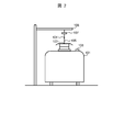
- the vehicle 101, the sensing unit 108, and the overhead wires (the trolley wire 103, the hinge wire 104, the hanger 105, the support 106, the insulator 107) of FIG. The positional relationship will be described in detail.
- the LIDAR is installed in the vehicle 101 so that the overhead wire can be scanned from an oblique direction centering on the contact point of the pantograph and the trolley wire 103.
- This is an idea that it is advantageous for the subsequent processing (matching processing described in FIG. 5) to capture more information of the feature points of the overhead wire, and to capture as many components of the overhead wire as possible. It is for. For example, when scanning from the position immediately below the trolley wire 103, in principle, the hanger 105 and the hinge wire 104 hanging the trolley wire 103 in the vertical direction are hidden behind the trolley wire 103, and the scan does not extend.
- the sensing unit 108 is provided at a position deviated from the position immediately below the trolley wire 103 and scanning obliquely from that position, the hanger 105 periodically tensioned and the overhead wire 104 periodically showing deflection.
- the scan can extend to the side of the and capture their features into the measurement data.
- the support 106 is usually made of a strong material such as a steel frame because it needs to support all the underlying structures including the hinge wire 104 and the trolley wire 103, and the size is extremely large among the structures of the wire. . For this reason, LIDAR is relatively easy to capture its three-dimensional shape. Since there is no fear of bending or shaking like electric wires, it can be said that each time the vehicle 101 travels, it can be caught by scanning by LIDAR, as well as relatively less overlooked each time.
- the supports 106 are usually built at intervals of several hundred meters.
- the map information 109 is a database in which the three-dimensional shape of the overhead wire across the trajectory 102 is stored in advance in association with the position information.
- a vehicle equipped with a LIDAR similar to or higher in resolution than the sensing unit 108 may be run in advance along the track, and the measurement data may be stored (processed as necessary).
- the correspondence between the three-dimensional shape obtained by measurement and the position can be realized by combining, for example, a method capable of measuring an absolute position with an error of about several tens of cm, such as a differential global positioning system (DGPS).
- DGPS differential global positioning system
- the method of creating a database is not limited to this as long as the same result as that obtained by this means is obtained.
- the map information 109 is information of a three-dimensional shape over the trajectory 102, the size of the data is relatively large.
- the method of storing the data is not particularly limited, but in the present embodiment, it is stored in a secondary storage device (a magnetic disk, an optical disk, a flash memory storage device, etc. and is not shown). Do. In the processing of the matching unit 110 described later, the map information 109 is read out and used on the main storage unit (not shown) for the necessary section.
- the data of the three-dimensional shape is constituted by X, Y, Z representing the coordinate system of the three-dimensional space and the value P at each point.
- X, Y, and Z are coordinates of each point obtained by dividing the three-dimensional space into a grid with a fineness (for example, several cm) sufficient to express the three-dimensional shape of the component of the overhead wire as a point group.
- the value P is a binary value representing the presence or absence of a point. For convenience, “1” indicates that there is a point, and “0” indicates that there is no point.
- a three-dimensional shape can be represented by a point group.
- the X, Y, and Z axes do not necessarily have to be orthogonal to each other at 90 degrees, and may be linearly independent so as to represent a three-dimensional space. For example, if X is taken along the trajectory 102, Y is taken across the trajectory, and Z is taken along the height, the value of X directly corresponds to the position on the trajectory 102. It is useful to describe the three-dimensional space along the 102 line.
- the matching unit 110 Among the three-dimensional shape data (map data) of the overhead wire stored in advance that is read from the map information 109, the matching unit 110 most closely matches the measurement data of the three-dimensional shape of the overhead wire received from the sensing unit 108. It is a means to identify one and identify the corresponding position. The identified position is output to the estimated position determination unit 111. Specific contents of processing will be described later with reference to FIGS. 4 and 5.
- the estimated position determination unit 111 is a unit that estimates the position of the vehicle 101 (determines the estimated position) from the position specified by the matching unit 110 and the travel distance of the vehicle 101 determined by the travel distance measurement unit 112 described below. is there. The contents of specific processing will be described later with reference to FIG.
- the determined estimated position is transmitted to the control unit 113.
- the travel distance measurement unit 112 measures the travel distance of the vehicle 101 and transmits the measured travel distance to the estimated position determination unit 111.
- the means for measuring the travel distance is not particularly limited.
- a means for calculating the travel distance by counting the number of revolutions of the wheel and multiplying it by the wheel diameter stored in advance is often used in a railway vehicle as described in the background art, and for example, the means is assumed.
- Another method is to calculate the travel distance by integrating the output of the speed sensor.
- the control unit 113 is an application of vehicle control using the estimated position of the vehicle 101.
- an automatic operation system ATO: Automatic Train Operation
- ATO Automatic Train Operation
- TASC Train Automatic Stopping-position Control
- the sensing unit 108 When the sensing unit 108 is mounted using LIDAR having ranging accuracy of several mm to several cm and the map information 109 is created, it is determined by the estimated position determination unit 111 unless the matching unit 110 reduces the amount of information.
- the estimated position can be expected to withstand the use of ATO with these functions.
- a signal system (ATP: Automatic Train Protection) that controls a brake to secure a safe distance between vehicles is also an example of an application using the estimated position of the vehicle 101.
- the sensing unit 108, the matching unit 110, the estimated position determination unit 111, the travel distance measurement unit 112, and the control unit 113 are CPU (Central Processing Unit)
- the program may be realized by reading and executing the program in the main storage (software), or by hardware such as a dedicated circuit, or by a combination of software and hardware. Good.
- some or all of the functions of the vehicle 101 may be realized by a computer that can communicate with the vehicle 101.
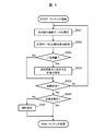
- steps S401 to S406 are executed by the matching unit 110. Each processing will be described below.
- step S401 the matching unit 110 determines a section on the trajectory 102 to which the subsequent processing is applied.
- the reason for determining the section is to read the map (map data) of the three-dimensional shape of the overhead line from the map information 109 by the amount of the section on the main storage device in the subsequent step S402. For this reason, how to select a section depends on the balance between the size of map data and the capacity of the main storage, but for practical purposes, for example, between stations is defined as one section and the map between the next stations while stopping at the station Reading the data is preferable because it is not necessary to read map data anew while traveling.
- step S402 the matching unit 110 reads map data from the map information 109 into the main storage device for the section determined in step S401.
- step S403 the matching unit 110 determines which range of the map data read on the main storage device is to be compared with the measurement data read from the sensing unit 108 in the next step S404 (setting of matching range) .
- step S405 the purpose of the comparison is to specify a candidate for the position of the vehicle 101 (vehicle position). For this reason, the track 102 on which the vehicle 101 travels is determined, and the track 102 predicts that the vehicle 101 is currently positioned within a reasonable range, as long as the vehicle 101 does not move rapidly from the position observed last time.
- the above predetermined range can be specified.
- the present processing is provided with the intention of narrowing the map data used for comparison with the measurement data in advance to this reasonable range and reducing the amount of calculation in the subsequent step S405.
- the way to determine the range is, for example, a loop from step S407 to step S403 after step S406 of specifying a vehicle position candidate as will be described later, so based on the vehicle position once specified in step S406, From that point, it can be determined by taking into consideration the distance that the vehicle 101 can travel in the cycle of the loop (for example, 100 ms).
- the range is set to [x0, x0 + 2 m] because it is about 2 m to travel for 100 ms.
- the information of the candidate of the position specified by step S406 does not exist at the time of the first execution of step S403, what is necessary is just to define a range on the basis of some initial position information, such as a position of a starting point station.
- step S404 the matching unit 110 receives the measurement data of the overhead wire measured by LIDAR from the sensing unit 108, and reads the data into the main storage device.
- the measurement data is compared with the map data read in the previous step S402 in the subsequent step S405, a conversion process is also performed simultaneously to make the formats of the two data comparable.
- step S404 calculates many times in the loop from step S403 to step S407, the map data is read in step S402 prior to converting the format of measurement data according to the format of map data. At this point, it is easier to calculate the loop if the format of the map data is set in advance to the format of the measurement data.
- step S405 the matching unit 110 finds one piece of data similar to the measurement data described above from the range defined by the map data described above, and specifies the corresponding position (matching process). The details of the matching process will be described later with reference to FIG.
- step S406 the matching unit 110 notifies the estimated position determination unit 111 of the position identified in step S405.
- step S407 the matching unit 110 determines whether the position identified in step S405 has reached the end of the section determined in step S401. If the matching unit 110 determines that the time has not reached, the process returns to step S403 to continuously estimate the position. The matching unit 110 ends the process determined to have reached. Thus, steps S403 to S407 form a loop.
- the calculation cycle is assumed to be, for example, about 100 ms as described above.
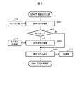
- step S405 details of step S405 will be described using the flowchart of FIG. Each process (steps S501 to S507) shown in FIG. 5 is executed by the matching unit 110. Each processing will be described below.
- step S501 the matching unit 110 selects one piece of map data to be used for comparison with the measurement data in the subsequent step S502.
- steps S501 to S505 form a loop.
- the intention is to cover map data within the matching range defined in step S403 described above.
- step S501 the matching unit 110 selects map data one after another from the start position of the matching range.
- step S502 the matching unit 110 compares the map data selected in step S501 with the measurement data to evaluate the similarity.
- the measure of similarity evaluation is not limited to this as long as it is suitable for the purpose.
- step S503 the matching unit 110 determines whether the evaluation value of the similarity obtained in step S502 satisfies a predetermined reference value (exceeds a threshold) (ie, in the case of the illustrated scale), the reference value To determine whether or not If the matching unit 110 determines that the condition is satisfied, the process proceeds to step S504. If the matching unit 110 determines that the condition is not satisfied, the process proceeds to step S505, skipping step S504.
- a predetermined reference value ie, in the case of the illustrated scale
- the intention of this determination process is to avoid adopting it as a candidate for the vehicle position no matter how similar the comparison is within the matching range if the similarity is below the reference value. For example, if the sensing unit 108 is broken or the ranging does not function normally due to bad weather etc., the measured data is not quite different from that of the originally expected map data, and as a result it is compared with the map data Even if the similarity that satisfies the criteria can not be obtained.
- the purpose of detecting the fact that the sensing unit 108 does not function properly that is, when the obtained estimated position can not be placed in confidence) by utilizing this is beyond the above-described intention.
- step S504 the matching unit 110 selects the one with the highest degree of similarity in step S502 among the matching areas currently set, selecting map data one after another in step S501, and specifies the position. At this time, as described in the description of step S 503, those whose similarity is lower than the reference value are not subjected to this process. That is, if the similarity of all map data in the matching range falls below the reference value, the position is not specified in step S504, and if at least one exceeds the reference value, the similarity is the maximum in step S504. Identify the location of These two are distinguished in step S504 for use in later step S506.
- step S505 the matching unit 110 determines whether the map data selected in step S501 has reached from the beginning to the end of the matching range (that is, whether the map data in the matching range is covered). If the matching unit 110 determines that the end has not been reached, the process returns to step S501, and if it is determined that the end has been reached, the process proceeds to step S506.
- step S506 the matching unit 110 determines whether the position has been identified in step S504 described above. If the matching unit 110 determines that the position has been identified, the processing ends as the vehicle position candidate, and if it is determined that the position is not identified, the determination processing of step S 503 is performed to obtain all the map data. Since each similarity is below the reference value, an abnormality is determined, and the process proceeds to step S507.
- step S507 instead of specifying the position, the matching unit 110 performs processing so that information indicating the occurrence of an exception is passed to the subsequent processing (step S406 in FIG. 4).
- step S405 the matching unit 110 clarified that the information of the position specified as the candidate of the vehicle position or the information indicating the occurrence of the exception is used in step S406.
- step S406 the matching unit 110 notifies the estimated position determination unit 111 of any information. For example, when an exception occurs in step S405, the estimated position determination unit 111 can also know the occurrence of the exception.
- step S601 the estimated position determination unit 111 reads the position identified by the matching unit 110 as a reference position.
- the information from the matching unit 110 may not be information indicating the identified position but information indicating an occurrence of an exception. In this case, the previously read reference position is left as it is.
- step S602 the estimated position determination unit 111 determines whether the information from the matching unit 110 read in step S601 is information indicating the occurrence of an exception. If the estimated position determination unit 111 determines that the information indicates the occurrence of an exception, the process proceeds to step S603, and if it is determined that the information does not indicate the occurrence of an exception, the process proceeds to step S604.
- step S603 the estimated position determination unit 111 reads the travel distance from the travel distance measurement unit 112, determines the travel distance since the previous reference position was set, and adds it to the reference position to determine the estimated position. End the process. Since the exception occurs when the similarity between the measurement data and the map data does not satisfy a certain criterion, this process, that is, when the reliability of the position specified by the matching unit 110 is not sufficient, This means that the position information is not reflected on the estimated position of the vehicle 101, and instead, based on the reliable position obtained last time, the information on the travel distance is used to supplement the estimation of the vehicle position.
- step S604 the estimated position determination unit 111 outputs the reference position determined in step S601 if no exception occurs, and outputs the estimated position determined in step S603 to the control unit 113 when the exception occurs. finish.
- the position of the vehicle 101 traveling on the track 102 is identified by using the three-dimensional shape of the power path equipment (overhead wire) developed above the vehicle 101. Can be estimated with high accuracy.
- estimation of the vehicle position is performed using information of travel distance measured by another means. By supplementing, the reliability of the estimated position can be maintained, and the control function of the vehicle 101 using the estimated position can be continued.
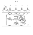
- FIG. 7 is a diagram showing an example of the configuration of a vehicle control system 700 according to the present embodiment. Compared with the configuration described in FIG. 1 in the first embodiment, the difference is that the designated position information 701 is added and that the estimated position determination unit 702 is changed accordingly, and the other description is given in FIG. It is the same as the configuration. The following mainly describes different configurations.
- the designated position information 701 is data in which a section in which the estimation of the vehicle position using the sensing unit 108 can be performed particularly reliably is recorded in advance.
- a section is, for example, a section that can catch the support 106 of the overhead wire.
- the support 106 is necessarily made of a strong material such as an iron column and relatively large among the components of the wire from its application. The reason is that the possibility of not being detected by the sensing unit 108 is relatively low. In addition, it may be a section passing under the elevated road, etc. It can be expected that the possibility of not being detected by the sensing unit 108 becomes relatively low even in such a section.
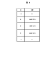
- the data format of the designated position information 701 will be described with reference to FIG.
- the designated position information 701 includes a designated position ID and a section of the designated position. As will be understood through the following description, it is only at this designated position that the position identified from the three-dimensional shape of the overhead line is reflected on the estimated position of the vehicle 101.
- the designated position ID is “A”, “B”, “C”, etc. in combination with the notation pointing to the support 106 in FIG. 7, but the designation position ID is not limited to this notation, and the designated position can be identified. Other notations may be used.
- the section at the designated position is set to point 10 m near the support 106.
- the sensing unit 108 can sense the support 106 from 5 m before and after the position of the support 106, and the range is a section of the designated position, but is not limited to this.
- the designated position may be represented by one point on the trajectory, and the estimated position determination unit 702 may determine the section based on that point.
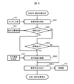
- step S901 is added between step S601 and step S602. It is similar.
- step S901 the estimated position determination unit 702 refers to the designated position information 701 and determines whether the position identified in step S405 is a designated position (whether or not it is within the section of the designated position). . If the estimated position determination unit 702 determines that it is a designated position, it moves the process to step S602, and if it determines that it is not a designated position, it moves the process to step S603, and thereafter, it is similar to the process described in FIG. Flow.
- the estimated position determination unit 111 sets the position identified in step S405 as the reference position only at the designated position by the same processing as that described with reference to FIG. 6 in the first embodiment. If there is no position, the vehicle position will be estimated based on the travel distance. In other words, apparently, the vehicle position is usually continuously estimated based on the travel distance, and the position is identified from the three-dimensional shape of the overhead wire with high accuracy and high reliability at the designated position that appears from time to time. It can be said that this is a mechanism for correcting accumulated errors.
- identification is performed using the three-dimensional shape of the power path equipment (overhead wire) developed above the vehicle 101,
- the position of the vehicle 101 traveling on the track 102 can be estimated with high accuracy.
- by narrowing the estimation of the vehicle position using the three-dimensional shape of the overhead wire to a section where it can be performed with relatively high accuracy and high reliability because of the characteristics of the three-dimensional shape the chance of mistaking the estimated position by misidentification is reduced. Can provide more reliable location information.
- the exception generated in step S405 can be latched (held) across the section, and correction can not be performed at the designated position if the exception occurs at a position other than the designated position.
- This is equivalent to performing processing of identifying the position from the three-dimensional shape of the overhead wire in the application of function diagnosis although it does not reflect the estimated position of the vehicle 101 at a position that is not a designated position.
- the occurrence of the exception is assumed to be a countermeasure against the case where a sufficiently accurate three-dimensional shape of the overhead wire can not be obtained due to an abnormality of the sensing unit 108 (ranging sensor), bad weather, etc. There is a great risk of failing to provide accurate position information even at the designated position. Therefore, more reliable location information in the sense that diagnosing the function at a position other than the designated position and stopping the function early when an abnormality is detected reduces the possibility of providing erroneous location information. Will provide.
- the present invention is applied to the vehicle control system 100, 700.
- the present invention is not limited to this.
- the present invention can be widely applied to various other vehicle control systems.
- the present invention is not limited thereto, for example, the vehicle 101 travels It is also possible to scan and match an overhead wire provided along another trajectory (for example, the trajectory 102 is an upward line, another trajectory is a downstream line) provided in parallel with the trajectory 102.
- the matching unit 110 is a data group indicating the three-dimensional shape of a structure provided in advance near the track 102 on which the vehicle 101 travels, and the three-dimensional shape of the object measured by the sensing unit 108. Processing of matching with a data group indicating.
- a data group indicating the three-dimensional shape of a structure provided in advance near the track 102 on which the vehicle 101 travels is associated with position information indicating the position of the structure. It is an example of a plurality of structure information.
- the track 102 is an upward line and the other track is a downward line. It is also possible to scan and match both of the overhead lines to be processed. When both overhead lines are to be subjected to the matching process, more matching processes can be performed than in the case of one overhead line, so that the estimated position of the vehicle 101 can be determined with higher accuracy.
Landscapes
- Engineering & Computer Science (AREA)
- Mechanical Engineering (AREA)
- Life Sciences & Earth Sciences (AREA)
- Sustainable Development (AREA)
- Sustainable Energy (AREA)
- Power Engineering (AREA)
- Transportation (AREA)
- Manufacturing & Machinery (AREA)
- Electric Propulsion And Braking For Vehicles (AREA)
- Train Traffic Observation, Control, And Security (AREA)
- Navigation (AREA)
Abstract
La présente invention comprend : une unité de détection qui est disposée dans un véhicule et mesure la forme tridimensionnelle d'un objet ; une unité de mise en correspondance pour effectuer une mise en correspondance entre de multiples ensembles d'informations de structure, dans lesquels sont associés un groupe de données indiquant les formes tridimensionnelles de structures fournies au préalable à proximité d'une trajectoire que le véhicule va parcourir et des informations de position indiquant les positions des structures, et un groupe de données indiquant la forme tridimensionnelle de l'objet mesurée par l'unité de détection, et pour spécifier la position de l'objet ; et une unité de détermination de position estimée pour déterminer, avec la position spécifiée par l'unité de mise en correspondance en tant que position de référence, la position estimée du véhicule sur la base de la position de référence.
Priority Applications (2)
| Application Number | Priority Date | Filing Date | Title |
|---|---|---|---|
| US16/764,901 US11453422B2 (en) | 2017-11-21 | 2018-10-23 | Vehicle control system |
| EP18880395.1A EP3715211A4 (fr) | 2017-11-21 | 2018-10-23 | Système de commande de véhicule |
Applications Claiming Priority (2)
| Application Number | Priority Date | Filing Date | Title |
|---|---|---|---|
| JP2017223631A JP6986936B2 (ja) | 2017-11-21 | 2017-11-21 | 車両制御システム |
| JP2017-223631 | 2017-11-21 |
Publications (1)
| Publication Number | Publication Date |
|---|---|
| WO2019102769A1 true WO2019102769A1 (fr) | 2019-05-31 |
Family
ID=66631577
Family Applications (1)
| Application Number | Title | Priority Date | Filing Date |
|---|---|---|---|
| PCT/JP2018/039320 Ceased WO2019102769A1 (fr) | 2017-11-21 | 2018-10-23 | Système de commande de véhicule |
Country Status (4)
| Country | Link |
|---|---|
| US (1) | US11453422B2 (fr) |
| EP (1) | EP3715211A4 (fr) |
| JP (1) | JP6986936B2 (fr) |
| WO (1) | WO2019102769A1 (fr) |
Families Citing this family (10)
| Publication number | Priority date | Publication date | Assignee | Title |
|---|---|---|---|---|
| JP6947699B2 (ja) * | 2018-07-25 | 2021-10-13 | 公益財団法人鉄道総合技術研究所 | 情報処理装置および点群位置補正方法、ならびにプログラム |
| JP7227879B2 (ja) * | 2019-09-02 | 2023-02-22 | 株式会社日立製作所 | 周辺観測システム、周辺観測プログラムおよび周辺観測方法 |
| JP7288380B2 (ja) * | 2019-10-04 | 2023-06-07 | 株式会社日立製作所 | データ記録装置及びデータ記録方法 |
| JP7349318B2 (ja) * | 2019-10-18 | 2023-09-22 | 株式会社日立製作所 | センサ性能評価システム及び方法、並びに、自動運転システム |
| KR20220045846A (ko) * | 2020-10-06 | 2022-04-13 | 현대자동차주식회사 | 트랙렛의 사전분포모델을 활용한 표적차량의 운동 및 형상 동시 추정방법 |
| CN112330647A (zh) * | 2020-11-12 | 2021-02-05 | 南京优视智能科技有限公司 | 一种动车车底异常检测方法 |
| ES2966194T3 (es) * | 2020-12-14 | 2024-04-18 | Siemens Rail Automation S A U | Sistema y método para medir la distancia recorrida por un vehículo guiado |
| CN117794805A (zh) * | 2021-08-02 | 2024-03-29 | 三菱电机株式会社 | 数据处理装置、数据处理方法和数据处理程序 |
| JP7822257B2 (ja) * | 2022-06-21 | 2026-03-02 | 株式会社日立製作所 | 速度算出装置、速度算出方法および移動体制御システム |
| US20250353377A1 (en) * | 2024-05-16 | 2025-11-20 | Komatsu America Corp. | Vehicle Having Pantograph End Adaptor and an Auto-Steering Guidance System |
Citations (8)
| Publication number | Priority date | Publication date | Assignee | Title |
|---|---|---|---|---|
| JPH09270013A (ja) * | 1996-04-02 | 1997-10-14 | Nippon Signal Co Ltd:The | 移動体位置検知装置 |
| JP2008247154A (ja) * | 2007-03-30 | 2008-10-16 | Kyosan Electric Mfg Co Ltd | 列車位置検知装置と列車制御装置 |
| JP2011201426A (ja) * | 2010-03-25 | 2011-10-13 | National Traffic Safety & Environment Laboratory | 列車搭載用画像処理システム |
| JP2013107434A (ja) | 2011-11-18 | 2013-06-06 | Nippon Signal Co Ltd:The | 車上装置、及び、自列車位置認識方法 |
| JP2014220858A (ja) | 2013-05-01 | 2014-11-20 | 株式会社日立製作所 | 位置検出装置及び位置検出方法 |
| JP2015093532A (ja) | 2013-11-11 | 2015-05-18 | 株式会社明電舎 | 電車の自己位置推定装置 |
| US20160221592A1 (en) * | 2013-11-27 | 2016-08-04 | Solfice Research, Inc. | Real Time Machine Vision and Point-Cloud Analysis For Remote Sensing and Vehicle Control |
| JP2017001638A (ja) * | 2015-06-16 | 2017-01-05 | 西日本旅客鉄道株式会社 | 画像処理を利用した列車位置検出システムならびに画像処理を利用した列車位置および環境変化検出システム |
Family Cites Families (5)
| Publication number | Priority date | Publication date | Assignee | Title |
|---|---|---|---|---|
| AUPP299498A0 (en) * | 1998-04-15 | 1998-05-07 | Commonwealth Scientific And Industrial Research Organisation | Method of tracking and sensing position of objects |
| KR101583707B1 (ko) * | 2013-11-12 | 2016-01-08 | 한국철도기술연구원 | 전차선 편위 정보를 이용한 고정밀 열차 위치 검지 시스템 |
| JP6389783B2 (ja) * | 2015-03-11 | 2018-09-12 | 公益財団法人鉄道総合技術研究所 | 渡り線相対位置管理装置及び方法 |
| US9711050B2 (en) * | 2015-06-05 | 2017-07-18 | Bao Tran | Smart vehicle |
| US11307042B2 (en) * | 2015-09-24 | 2022-04-19 | Allstate Insurance Company | Three-dimensional risk maps |
-
2017
- 2017-11-21 JP JP2017223631A patent/JP6986936B2/ja active Active
-
2018
- 2018-10-23 WO PCT/JP2018/039320 patent/WO2019102769A1/fr not_active Ceased
- 2018-10-23 EP EP18880395.1A patent/EP3715211A4/fr active Pending
- 2018-10-23 US US16/764,901 patent/US11453422B2/en active Active
Patent Citations (8)
| Publication number | Priority date | Publication date | Assignee | Title |
|---|---|---|---|---|
| JPH09270013A (ja) * | 1996-04-02 | 1997-10-14 | Nippon Signal Co Ltd:The | 移動体位置検知装置 |
| JP2008247154A (ja) * | 2007-03-30 | 2008-10-16 | Kyosan Electric Mfg Co Ltd | 列車位置検知装置と列車制御装置 |
| JP2011201426A (ja) * | 2010-03-25 | 2011-10-13 | National Traffic Safety & Environment Laboratory | 列車搭載用画像処理システム |
| JP2013107434A (ja) | 2011-11-18 | 2013-06-06 | Nippon Signal Co Ltd:The | 車上装置、及び、自列車位置認識方法 |
| JP2014220858A (ja) | 2013-05-01 | 2014-11-20 | 株式会社日立製作所 | 位置検出装置及び位置検出方法 |
| JP2015093532A (ja) | 2013-11-11 | 2015-05-18 | 株式会社明電舎 | 電車の自己位置推定装置 |
| US20160221592A1 (en) * | 2013-11-27 | 2016-08-04 | Solfice Research, Inc. | Real Time Machine Vision and Point-Cloud Analysis For Remote Sensing and Vehicle Control |
| JP2017001638A (ja) * | 2015-06-16 | 2017-01-05 | 西日本旅客鉄道株式会社 | 画像処理を利用した列車位置検出システムならびに画像処理を利用した列車位置および環境変化検出システム |
Non-Patent Citations (1)
| Title |
|---|
| See also references of EP3715211A4 |
Also Published As
| Publication number | Publication date |
|---|---|
| US11453422B2 (en) | 2022-09-27 |
| JP2019093840A (ja) | 2019-06-20 |
| JP6986936B2 (ja) | 2021-12-22 |
| EP3715211A1 (fr) | 2020-09-30 |
| EP3715211A4 (fr) | 2021-08-18 |
| US20200339171A1 (en) | 2020-10-29 |
Similar Documents
| Publication | Publication Date | Title |
|---|---|---|
| WO2019102769A1 (fr) | Système de commande de véhicule | |
| US11113543B2 (en) | Facility inspection system and facility inspection method | |
| AU2018425917B2 (en) | Apparatus and method for calculating wooden crosstie plate cut measurements and rail seat abrasion measurements based on rail head height | |
| US20150145962A1 (en) | Railway installation synchronization monitoring system | |
| US10740936B2 (en) | Trolley-wire display device, trolley-wire display system, and trolley-wire display data creation method | |
| JP5965251B2 (ja) | 軌道位置データ付与システム及び軌道位置データ付与方法 | |
| CN104541124B (zh) | 利用激光测定的支撑物探测装置 | |
| JP2021512813A (ja) | 鉄道車両および軌道区間を検測する方法 | |
| US10919550B2 (en) | Method and positioning device for determining the position of a track-guided vehicle, in particular a rail vehicle | |
| JP2014169939A (ja) | 架線位置計測装置及び方法 | |
| WO2021075210A1 (fr) | Système et procédé d'évaluation de performance de capteur, et système d'entraînement automatique | |
| JP5476775B2 (ja) | トロリ線検測装置及び検測方法 | |
| EP3069955A1 (fr) | Dispositif d'estimation d'auto-positionnement de train | |
| EP3392605B1 (fr) | Appareil de mesure de fil conducteur et procédé de mesure de fil conducteur | |
| KR101583707B1 (ko) | 전차선 편위 정보를 이용한 고정밀 열차 위치 검지 시스템 | |
| WO2023084728A1 (fr) | Dispositif de détermination de distance de marque de distance, procédé de détermination de distance de marque de distance et programme de détermination de distance de marque de distance | |
| EP4545377A1 (fr) | Dispositif de calcul de vitesse, procédé de calcul de vitesse et système de commande d'objet mobile | |
| KR102820495B1 (ko) | 열차의 위치를 측정하는 열차 측위 장치 및 방법 | |
| EP4578759A1 (fr) | Système d'estimation d'emplacement et procédé d'estimation d'emplacement | |
| JP5889041B2 (ja) | 走行道路判定装置及びその処理方法とプログラム | |
| JP2026035006A (ja) | 車両位置算出方法及び車両位置算出システム | |
| HK40008164B (en) | Trolley wire display device, trolley wire display system, and trolley wire display data creation method | |
| HK40008164A (en) | Trolley wire display device, trolley wire display system, and trolley wire display data creation method |
Legal Events
| Date | Code | Title | Description |
|---|---|---|---|
| 121 | Ep: the epo has been informed by wipo that ep was designated in this application |
Ref document number: 18880395 Country of ref document: EP Kind code of ref document: A1 |
|
| DPE1 | Request for preliminary examination filed after expiration of 19th month from priority date (pct application filed from 20040101) | ||
| NENP | Non-entry into the national phase |
Ref country code: DE |
|
| ENP | Entry into the national phase |
Ref document number: 2018880395 Country of ref document: EP Effective date: 20200622 |