WO2019102980A1 - Fil tressé et faisceau de fils - Google Patents
Fil tressé et faisceau de fils Download PDFInfo
- Publication number
- WO2019102980A1 WO2019102980A1 PCT/JP2018/042758 JP2018042758W WO2019102980A1 WO 2019102980 A1 WO2019102980 A1 WO 2019102980A1 JP 2018042758 W JP2018042758 W JP 2018042758W WO 2019102980 A1 WO2019102980 A1 WO 2019102980A1
- Authority
- WO
- WIPO (PCT)
- Prior art keywords
- wire
- braided
- strand
- harness
- braided wire
- Prior art date
- Legal status (The legal status is an assumption and is not a legal conclusion. Google has not performed a legal analysis and makes no representation as to the accuracy of the status listed.)
- Ceased
Links
Images


Classifications
-
- B—PERFORMING OPERATIONS; TRANSPORTING
- B60—VEHICLES IN GENERAL
- B60R—VEHICLES, VEHICLE FITTINGS, OR VEHICLE PARTS, NOT OTHERWISE PROVIDED FOR
- B60R16/00—Electric or fluid circuits specially adapted for vehicles and not otherwise provided for; Arrangement of elements of electric or fluid circuits specially adapted for vehicles and not otherwise provided for
- B60R16/02—Electric or fluid circuits specially adapted for vehicles and not otherwise provided for; Arrangement of elements of electric or fluid circuits specially adapted for vehicles and not otherwise provided for electric constitutive elements
-
- H—ELECTRICITY
- H01—ELECTRIC ELEMENTS
- H01B—CABLES; CONDUCTORS; INSULATORS; SELECTION OF MATERIALS FOR THEIR CONDUCTIVE, INSULATING OR DIELECTRIC PROPERTIES
- H01B5/00—Non-insulated conductors or conductive bodies characterised by their form
- H01B5/12—Braided wires or the like
-
- H—ELECTRICITY
- H01—ELECTRIC ELEMENTS
- H01B—CABLES; CONDUCTORS; INSULATORS; SELECTION OF MATERIALS FOR THEIR CONDUCTIVE, INSULATING OR DIELECTRIC PROPERTIES
- H01B7/00—Insulated conductors or cables characterised by their form
-
- H—ELECTRICITY
- H01—ELECTRIC ELEMENTS
- H01B—CABLES; CONDUCTORS; INSULATORS; SELECTION OF MATERIALS FOR THEIR CONDUCTIVE, INSULATING OR DIELECTRIC PROPERTIES
- H01B7/00—Insulated conductors or cables characterised by their form
- H01B7/04—Flexible cables, conductors, or cords, e.g. trailing cables
-
- H—ELECTRICITY
- H01—ELECTRIC ELEMENTS
- H01B—CABLES; CONDUCTORS; INSULATORS; SELECTION OF MATERIALS FOR THEIR CONDUCTIVE, INSULATING OR DIELECTRIC PROPERTIES
- H01B7/00—Insulated conductors or cables characterised by their form
- H01B7/17—Protection against damage caused by external factors, e.g. sheaths or armouring
- H01B7/18—Protection against damage caused by wear, mechanical force or pressure; Sheaths; Armouring
-
- H—ELECTRICITY
- H02—GENERATION; CONVERSION OR DISTRIBUTION OF ELECTRIC POWER
- H02G—INSTALLATION OF ELECTRIC CABLES OR LINES, OR OF COMBINED OPTICAL AND ELECTRIC CABLES OR LINES
- H02G3/00—Installations of electric cables or lines or protective tubing therefor in or on buildings, equivalent structures or vehicles
- H02G3/02—Details
- H02G3/04—Protective tubing or conduits, e.g. cable ladders or cable troughs
Definitions
- the present invention relates to a braided wire and a wire harness.
- a braided wire formed by weaving a plurality of strands into a tubular shape is used in a wire harness used for a vehicle such as an automobile.
- a copper-based wire such as a bare soft copper wire, an oxygen-free soft copper wire, or a tin-plated soft copper wire has been used as a wire forming a braided wire of this type.
- the present invention has been made in view of the above background, and an object of the present invention is to provide a braided wire capable of suppressing the breakage of a strand due to vibration and a wire harness using the same.
- One aspect of the present invention is a tubular braided wire having a plurality of braided strands,
- the wire is made of aluminum wire or aluminum alloy wire,
- the outer shape of the wire is a braided wire having a pair of substantially parallel linear portions when viewed in a cross section perpendicular to the wire axis.
- Another aspect of the present invention is a wire harness having the above-mentioned braided wire.
- the wire constituting the braided wire is composed of an aluminum wire or an aluminum alloy wire, and when viewed in a cross section perpendicular to the wire axis, the wire has a pair of straight portions having a substantially parallel outer shape of the wire. doing.
- the strands are in point contact with each other in the braided portion of the strand, whereas in the braided wire, the strands are in surface contact with each other in the braided portion of the strand. Therefore, according to the said braided wire, the stress by the vibration concerning the contact part of strands can be relieved, and a disconnection of a strand can be controlled.
- the wire harness has the braided wire. Therefore, in the above-mentioned wire harness, even when vibration is loaded, disconnection of the strands of wire in the braided wire is suppressed. So, according to the said wire harness, the shield reliability by a braided wire can be improved.
- FIG. 1 is an external view schematically showing a braided wire of Example 1; It is the figure which showed typically the II-II line cross section in FIG. It is the figure which showed typically the cross section perpendicular
- FIG. It is the figure which showed typically the wire harness of Example 1, and the application example of the said wire harness.
- the wires are made of aluminum wires or aluminum alloy wires.
- an aluminum alloy 1000 series Al alloy, 3000 series Al alloy, 5000 series Al alloy, 6000 series Al alloy, 7000 series Al alloy etc. can be illustrated, for example.
- an aluminum alloy for example, 0.1% to 1.5% of Mg, 0.03% to 2.0% of Si, 0.05% or more of Cu in mass%
- An example is an aluminum alloy having a chemical composition which contains 0.5% or less, the balance is Al and unavoidable impurities, and the mass ratio Mg / Si of Mg and Si is 0.8 or more and 3.5 or less. it can.
- the aluminum alloy having the above-mentioned chemical composition can have a tensile strength of 200 MPa or more and a conductivity of 50% IACS or more.
- the chemical composition may further contain at least one element of Fe: 0.1% to 1.0% and Cr: 0.01% to 0.5% by mass%. it can. Moreover, the said chemical composition can further contain at least 1 element of Ti: 500 ppm or less and B: 50 ppm or less by a mass ratio.
- the plurality of strands constituting the braided wire may be composed of aluminum wires or aluminum alloy wires of the same material, or aluminum wires or aluminum alloy wires of different materials. It is also good.
- the former configuration in the entire braided wire, variations in bending characteristics of the strands are less likely to occur, and the bending characteristics are easily made uniform. Therefore, according to the configuration of the former, even in the case where bending and distortion are repeatedly received, it is difficult to generate a portion which is easily broken locally, and it becomes easy to suppress the breakage of the wire due to the vibration.
- an aluminum wire or an aluminum alloy wire may have a chemical conversion film, an alumite film (anodic oxide film), a rust preventive film, etc. on the surface.
- a chemical conversion film an alumite film (anodic oxide film), a rust preventive film, etc.
- the friction coefficient of the surface of the wire is reduced compared to the bare aluminum-based wire, and the slipperiness of the wires is easily improved, so that the above-described abrasion corrosion due to the vibration is easily suppressed.
- the outer shape of the strand has a pair of substantially parallel linear portions when viewed in a cross section perpendicular to the strand axis.
- substantially parallel means not only when the pair of linear portions is completely parallel but also, for the one linear portion of the pair of linear portions, the other linear portion is ⁇ 10
- the case of being inclined at an inclination angle of 10 degrees or more is also included.
- the strands in the braided wire can be formed, for example, by compressing and flattening a strand having a circular outer shape in a cross section perpendicular to the strand axis.
- the wire has a ratio of a distance between a pair of straight portions to a cross-sectional area of a cross section perpendicular to the wire axis ( ⁇ distance between a pair of straight portions> / ⁇ a wire cross section perpendicular to the wire axis
- the cross-sectional area of ( 1 ) can be 5 mm -1 or more and 20 mm -1 or less. According to this configuration, when forming a strand by compressing and flattening the strand whose outer shape is circular, a corner that may damage the adjacent strand at both ends of the pair of linear portions to be formed It is hard to form the corner where it stood.
- the length of the pair of linear portions is not too short, and the pair of flat surfaces is reliably formed on the outer surface of the strand by the compression. Therefore, according to the above configuration, surface contact between the strands of wire can be ensured in the braided portion of the strand, and a braided wire that can easily obtain the effect of suppressing wire breakage can be obtained.
- the distance between a pair of linear portions ten perpendiculars perpendicular to one linear portion are drawn at equal intervals on one linear portion, and these perpendiculars are respectively cut off by a pair of linear portions. It is taken as the average value of perpendicular length.
- the ratio of the distance between a pair of linear portions to the cross-sectional area of the cross section perpendicular to the strand axis is preferably 5 in view of facilitating the formation of corner portions that may damage the adjacent strands described above. .5mm -1 or more, more preferably, 6 mm -1 or more, more preferably, 6.5 mm -1 or higher, even more preferably, it may be 6.7 mm -1 or higher.
- the ratio of the distance between the pair of linear portions to the cross-sectional area of the cross section perpendicular to the strand axis is preferably 19 mm -1 or less, from the viewpoint of promoting surface contact between the strands in the braided portion of the strand. More preferably, it can be 18 mm ⁇ 1 or less, more preferably 17 mm 1 or less, and even more preferably 16 mm 1 or less.
- the said braided wire WHEREIN The external shape of a strand can be set as the structure which has a pair of circular arc-shaped part which connects between the edge parts of the same side in a pair of linear part. According to this configuration, it is easy to suppress damage between adjacent strands. Therefore, according to this configuration, it is possible to obtain a braided wire that is advantageous for suppressing disconnection due to vibration.
- the outline of a strand it is good for the outline of a strand to be, for example, a rounded rectangular shape. According to this configuration, it is ensured that the outer shape of the strand has the pair of linear portions and the pair of arc-shaped portions. Therefore, the effect mentioned above can be made reliable.
- the rounded rectangular shape can also be referred to as a track shape used in athletics and the like.
- the breaking rate of the wire is preferably 30% or less, more preferably 25% or less, still more preferably 20% or less, from the viewpoint of improving the applicability to the vibration site in the vehicle. It is good.
- the measuring method of the disconnection rate of the strand in a braided wire is later mentioned by an experiment example.
- the wire harness has the braided wire.
- the wire harness may be configured such that at least a harness end is covered by the braided wire. At the end of the harness, the wires of the wire harness are often exposed. According to the above configuration, even if the wire is exposed at the end of the harness, the wire can be covered with the braided wire, and the wire of the braided wire is unlikely to be broken due to rubbing of the wires due to vibration. Therefore, according to the above configuration, it is possible to obtain a wire harness having a high reliability of shielding by a braided wire.
- the wire harness may be configured to be connected to the vibration site outside of the vehicle.
- a vehicle a car, a train, a train, a motorcycle, etc. can be illustrated, for example.
- the wire of the braided wire is hard to break, and therefore, a wire harness for a vehicle having high reliability of shielding by the braided wire can be obtained.
- the wire harness includes an electric wire, a protective material covering the outer periphery of the electric wire, a connector connected to the electric wire exposed from the protective material at the harness end, an end of the protective material and an end of the connector And the braided wire covering the outer periphery of the electric wire exposed from the protective material.
- a protective material a metal pipe etc. can be illustrated, for example. According to this configuration, when the connector of the wire harness is connected to the vibrating portion, even if the braided wire vibrates repeatedly due to the vibration of the vibrating portion, the strands of the braided wire are less likely to be broken. High quality wire harness can be obtained.
- an engine of vehicles such as a motor vehicle, a door opening and closing part (bending part), a motor, a battery, etc. can be illustrated.
- Example 1 The braided wire of Example 1 will be described with reference to FIGS. 1 to 3.
- FIG. As shown in FIGS. 1 to 3, the braided wire 1 of the present example has a plurality of braided wires 2.
- the shape of the braided wire 1 is cylindrical.
- each strand 2 is abbreviate
- the strands 2 are made of an aluminum wire or an aluminum alloy wire.
- the outer shape of the strand 2 includes a pair of substantially parallel linear portions 21 a and 21 b when viewed in a cross section perpendicular to the strand axis 20.
- the external shape of the strand 2 has a pair of arc-shaped parts 22a and 22b which connect between the edge part of the same side in a pair of linear parts 21a and 21b.
- the strands 2 are formed by compressing and flattening a strand (not shown) having a circular outer shape when viewed in a cross section perpendicular to the strand axis.
- the outer shape of the strand 2 is a rounded rectangular shape.
- the width w of the strands 2 shown in FIG. 3 can be, for example, 0.78 mm
- the height h of the strands 2 can be, for example, 0.26 mm.
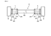
- the wire harness of Example 1 will be described with reference to FIG. As shown in FIG. 4, the wire harness 3 of this example has the braided wire 1 of this example.
- the wire harness 3 includes the electric wire 31, the protective material 32 covering the outer periphery of the electric wire 31, and the connector 33 connected to the electric wire 31 exposed from the protective material 32 at the harness end 30.
- a braided wire 1 is fixed to the end of the protective material 32 and the end of the connector 33 and covers the outer periphery of the electric wire 31 exposed from the protective material 32.
- FIG. 4 an example is shown in which both harness ends 30 are covered by the braided wire 1.
- the protective material 32 is specifically a metal pipe.
- the connector 33 on the one harness end 30 side is connected to the engine of the automobile which is the first vibration portion 4. Further, the connector 33 on the other harness end 30 side is connected to the battery of the automobile which is the second vibrating portion 5.
- the wire harness 3 of this example is a wire harness for underfloors arranged outside the car.
- the braided wire 1 is fixed to the end of the protective material 32 by caulking the ring member 34.
- the braided wire 1 is fixed to the end of the connector 33 by being tightened by a band member 35.
- Al alloy wire (diameter: 0.26 mm) made of an aluminum alloy whose outer shape of the wire is a circular shape in cross section perpendicular to the wire axis was prepared.
- Aluminum alloy contains, by mass%, 0.1% to 1.5% of Mg, 0.03% to 2.0% of Si, 0.05% to 0.5% of Cu, the balance Is composed of Al and unavoidable impurities, and has a chemical composition in which the mass ratio Mg / Si of Mg and Si is 0.8 or more and 3.5 or less.
- the prepared Al alloy wire is compressed by a roller made of cemented carbide W to obtain three types of flattened Al alloy wires (1), (2) and (3) having a compression ratio of 30%, 50% and 70%.
- the Each flattened Al alloy wire had a rounded rectangular shape when viewed in a cross section perpendicular to the wire axis.
- the ratio of the distance between the pair of linear portions to the cross-sectional area of the cross section perpendicular to the strand axis was 16.01 mm ⁇ 1 .
- the ratio of the distance between the pair of linear portions to the cross-sectional area of the cross section perpendicular to the strand axis was 11.49 mm ⁇ 1 .
- the ratio of the distance between the pair of linear portions to the cross-sectional area of the cross section perpendicular to the strand axis was 6.78 mm ⁇ 1 for the flattened Al alloy wire (3) having a compression ratio of 70%.
- the compression ratio (%) is a value calculated from 100 ⁇ (distance between a pair of linear portions after compression) / (wire diameter before compression).
- a braided wire of Sample 1 was obtained by knitting a plurality of flattened Al alloy wires (1) into a tubular shape.
- a braided wire of Sample 2 was obtained by knitting a plurality of flattened Al alloy wires (2) into a tubular shape.
- a braided wire of Sample 3 was obtained by knitting a plurality of flattened Al alloy wires (3) into a tubular shape.
- a braided wire of Sample 4 was obtained by braiding a plurality of Al alloy wires (wire diameter: 0.34 mm) having a circular outer shape before flattening and compression treatment with the above-mentioned rollers to obtain a tubular shape.
- the number of strikes was 44 and the number of holdings was 4.
- the disconnection rate was calculated
- the case where the wire breakage rate is 10% or less is regarded as “A” as being excellent in the wire wire breakage suppressing effect due to the vibration.
- the wire breakage rate is more than 10% and 30% or less, the wire breakage due to vibration can be suppressed as "B".
- the breaking rate of the braided wire of sample 1 is 18%, the judgment is “B”, the breaking rate of the braided wire of sample 2 is 9%, and the judgment is “A”, sample 3
- the breaking rate in the braided wire of the invention was 21%, the judgment was “B”, the breaking rate in the braided wire of the sample 4 was 32.5%, and the judgment was "C”.
- the strand has a pair of substantially parallel linear portions It was confirmed that the wire breakage can be suppressed by adopting the configuration, even if vibration is repeatedly applied in a strained state. This is because the strands come into surface contact with each other at the braided portion of the strands, so that the stress due to the vibration applied to the contact portion between the strands is relaxed.
Landscapes
- Engineering & Computer Science (AREA)
- Insulated Conductors (AREA)
- Architecture (AREA)
- Civil Engineering (AREA)
- Structural Engineering (AREA)
- Mechanical Engineering (AREA)
- Details Of Indoor Wiring (AREA)
- Conductive Materials (AREA)
Abstract
L'invention concerne un fil tressé (1) qui peut supprimer une rupture de brin due à une vibration, et un faisceau de fils (3) qui utilise celui-ci. Le fil tressé (1) comprend une pluralité de brins (2) qui sont tressés ensemble. La forme du fil tressé (1) est de forme cylindrique. Les brins (2) sont construits à partir d'un fil d'aluminium ou d'un fil d'alliage d'aluminium. Vu dans une section transversale perpendiculaire à un axe de brin (20), la forme extérieure de chaque brin (2) a une paire de sections droites sensiblement parallèles (21a), (21b).
Applications Claiming Priority (2)
| Application Number | Priority Date | Filing Date | Title |
|---|---|---|---|
| JP2017-225288 | 2017-11-23 | ||
| JP2017225288A JP2019096493A (ja) | 2017-11-23 | 2017-11-23 | 編組線およびワイヤーハーネス |
Publications (1)
| Publication Number | Publication Date |
|---|---|
| WO2019102980A1 true WO2019102980A1 (fr) | 2019-05-31 |
Family
ID=66631048
Family Applications (1)
| Application Number | Title | Priority Date | Filing Date |
|---|---|---|---|
| PCT/JP2018/042758 Ceased WO2019102980A1 (fr) | 2017-11-23 | 2018-11-20 | Fil tressé et faisceau de fils |
Country Status (2)
| Country | Link |
|---|---|
| JP (1) | JP2019096493A (fr) |
| WO (1) | WO2019102980A1 (fr) |
Citations (7)
| Publication number | Priority date | Publication date | Assignee | Title |
|---|---|---|---|---|
| JPS5435384U (fr) * | 1977-08-15 | 1979-03-08 | ||
| JP2003297157A (ja) * | 2002-04-08 | 2003-10-17 | Okano Densen Kk | 同軸ケーブル |
| JP2004171952A (ja) * | 2002-11-20 | 2004-06-17 | Auto Network Gijutsu Kenkyusho:Kk | シールド機能を備えた導電路 |
| JP2008192385A (ja) * | 2007-02-02 | 2008-08-21 | Fuji Densen Kogyo Kk | 同軸ケーブル、及び同軸ケーブル用内部導体の製造方法 |
| JP2009218037A (ja) * | 2008-03-10 | 2009-09-24 | Furukawa Electric Co Ltd:The | 自己収縮編組線及びその製造方法 |
| JP2013099074A (ja) * | 2011-10-31 | 2013-05-20 | Yazaki Corp | ワイヤハーネス |
| JP2013125754A (ja) * | 2011-12-13 | 2013-06-24 | Yazaki Corp | 電気接続部の固定構造、コネクタ、コネクタの接続方法 |
-
2017
- 2017-11-23 JP JP2017225288A patent/JP2019096493A/ja active Pending
-
2018
- 2018-11-20 WO PCT/JP2018/042758 patent/WO2019102980A1/fr not_active Ceased
Patent Citations (7)
| Publication number | Priority date | Publication date | Assignee | Title |
|---|---|---|---|---|
| JPS5435384U (fr) * | 1977-08-15 | 1979-03-08 | ||
| JP2003297157A (ja) * | 2002-04-08 | 2003-10-17 | Okano Densen Kk | 同軸ケーブル |
| JP2004171952A (ja) * | 2002-11-20 | 2004-06-17 | Auto Network Gijutsu Kenkyusho:Kk | シールド機能を備えた導電路 |
| JP2008192385A (ja) * | 2007-02-02 | 2008-08-21 | Fuji Densen Kogyo Kk | 同軸ケーブル、及び同軸ケーブル用内部導体の製造方法 |
| JP2009218037A (ja) * | 2008-03-10 | 2009-09-24 | Furukawa Electric Co Ltd:The | 自己収縮編組線及びその製造方法 |
| JP2013099074A (ja) * | 2011-10-31 | 2013-05-20 | Yazaki Corp | ワイヤハーネス |
| JP2013125754A (ja) * | 2011-12-13 | 2013-06-24 | Yazaki Corp | 電気接続部の固定構造、コネクタ、コネクタの接続方法 |
Also Published As
| Publication number | Publication date |
|---|---|
| JP2019096493A (ja) | 2019-06-20 |
Similar Documents
| Publication | Publication Date | Title |
|---|---|---|
| JP4804860B2 (ja) | 複合撚線導体 | |
| JP6114331B2 (ja) | 耐屈曲電線及びワイヤハーネス | |
| JP6080336B2 (ja) | 電線・ケーブル | |
| US12224079B2 (en) | Copper-coated steel wire, spring, stranded wire, insulated electric wire, and cable | |
| US20150213922A1 (en) | Electrical wire | |
| CN105408966B (zh) | 高频电线及其制造方法和线束 | |
| KR102453495B1 (ko) | 절연 전선용 연선 도체, 절연 전선, 코드 및 케이블 | |
| US20200021044A1 (en) | Connection structure | |
| JP2018129119A (ja) | アルミ複合撚線導体、アルミ複合撚線電線及びワイヤハーネス | |
| JP4799208B2 (ja) | 操作用インナーケーブル | |
| CN113811958B (zh) | 铜包钢线、绞合线、绝缘电线及线缆 | |
| US10875478B2 (en) | Wire harness | |
| WO2019102980A1 (fr) | Fil tressé et faisceau de fils | |
| JP7405789B2 (ja) | 電線及びワイヤーハーネス | |
| JP6845999B2 (ja) | 被覆電線、端子付き電線、及び撚線 | |
| WO2019102978A1 (fr) | Fil d'aluminium, conducteur à fil torsadé, fil tressé, et faisceau de câbles | |
| JP2008159403A (ja) | 電線導体および絶縁電線 | |
| JP4938403B2 (ja) | 繊維複合電線導体及び絶縁電線 | |
| JP6901934B2 (ja) | 編組及びワイヤーハーネス | |
| JP2016100269A (ja) | 送電線および送電線の製造方法 | |
| JP2009295326A (ja) | 架空送電線 | |
| JP5938162B2 (ja) | 自動車用電線 | |
| JP2017174548A (ja) | 編組線 | |
| JP6702258B2 (ja) | 編組線 | |
| JP2008027640A (ja) | 高強度化した銅合金線を用いた自動車用電線 |
Legal Events
| Date | Code | Title | Description |
|---|---|---|---|
| 121 | Ep: the epo has been informed by wipo that ep was designated in this application |
Ref document number: 18881365 Country of ref document: EP Kind code of ref document: A1 |
|
| NENP | Non-entry into the national phase |
Ref country code: DE |
|
| 122 | Ep: pct application non-entry in european phase |
Ref document number: 18881365 Country of ref document: EP Kind code of ref document: A1 |