WO2019103123A1 - Corps assemblé, procédé pour sa production et dispositif de soudage - Google Patents
Corps assemblé, procédé pour sa production et dispositif de soudage Download PDFInfo
- Publication number
- WO2019103123A1 WO2019103123A1 PCT/JP2018/043276 JP2018043276W WO2019103123A1 WO 2019103123 A1 WO2019103123 A1 WO 2019103123A1 JP 2018043276 W JP2018043276 W JP 2018043276W WO 2019103123 A1 WO2019103123 A1 WO 2019103123A1
- Authority
- WO
- WIPO (PCT)
- Prior art keywords
- width
- heating
- raw
- pair
- welding
- Prior art date
- Legal status (The legal status is an assumption and is not a legal conclusion. Google has not performed a legal analysis and makes no representation as to the accuracy of the status listed.)
- Ceased
Links
Images


Classifications
-
- B—PERFORMING OPERATIONS; TRANSPORTING
- B29—WORKING OF PLASTICS; WORKING OF SUBSTANCES IN A PLASTIC STATE IN GENERAL
- B29C—SHAPING OR JOINING OF PLASTICS; SHAPING OF MATERIAL IN A PLASTIC STATE, NOT OTHERWISE PROVIDED FOR; AFTER-TREATMENT OF THE SHAPED PRODUCTS, e.g. REPAIRING
- B29C65/00—Joining or sealing of preformed parts, e.g. welding of plastics materials; Apparatus therefor
- B29C65/02—Joining or sealing of preformed parts, e.g. welding of plastics materials; Apparatus therefor by heating, with or without pressure
Definitions
- the present invention relates to a joined body, a method of manufacturing the same, and a welding apparatus.
- Thermoplastic resin films are used in various applications such as coating materials for membrane structures and agricultural coating materials.
- the width of the thermoplastic resin film is less than the required width, the end portions in the width direction of the thermoplastic resin film are bonded to each other and used as a bonded body.
- a welding method is often used industrially (for example, Patent Documents 1 to 3). Bonding by welding is, for example, a pair of endless belts that run by sandwiching two thermoplastic resin films in a state in which the end portions in the width direction are overlapped, and installed opposite to the traveling path, It is carried out using a welding device provided with a heating mechanism which heats while pressing an overlapping portion of a sheet of thermoplastic resin film.
- Coating materials for membrane structures and agricultural coating materials are often fixed to a frame and used.
- the conventional bonded body has a problem that the surface is easily scratched by rubbing with the frame or the like during transportation or fixing to the frame. Scratches on the surface of the bonded body cause appearance defects and a reduction in yield.
- An object of the present invention is to provide a conjugate excellent in scratch resistance. Another object of the present invention is to provide a method of producing a joined body capable of suppressing the occurrence of wrinkles when joining thermoplastic resin films, and a welding apparatus suitably used for the production method.
- the present invention provides a joined body, a method for producing the same, and a welding apparatus having the following constitutions [1] to [15].
- a joined body in which at least two sheets of a raw material comprising a thermoplastic resin film are joined A joined body characterized in that the root mean square height of the surface undulation shape measured at a position of 50 mm outside from the outer edge in the width direction of the joined portions of adjacent raw webs is 0.5 mm or less.
- thermoplastic resin film is a film of a crystalline resin.
- thermoplastic resin film is a fluorine resin film.
- the above-mentioned fluorine resin is ethylene-tetrafluoroethylene copolymer, perfluoro (alkyl vinyl ether) -tetrafluoroethylene copolymer, hexafluoropropylene-tetrafluoroethylene copolymer, chlorotrifluoroethylene polymer, vinyl fluoride Polymer, vinylidene fluoride polymer, vinylidene fluoride-hexafluoropropylene copolymer, tetrafluoroethylene-hexafluoropropylene-vinylidene fluoride copolymer, tetrafluoroethylene-propylene copolymer, tetrafluoroethylene-vinylidene At least one member selected from the group consisting of a fluoride-propylene copolymer, an ethylene-chlorotrifluoroethylene copolymer, and a propylene-chlorotrifluoroethylene copolymer [ Conju
- the pair of endless belts are rotated so that the opposing portions travel forward, and two original rolls made of thermoplastic resin film are overlapped with the end portions in the width direction of the respective raw rolls.
- a welding target area including a portion in which the two raw sheets are in contact with each other while being held between the outer peripheral surfaces of the opposing portions of the pair of endless bands in a state where they are brought together or in contact.
- the temperature measured by the thermocouple disposed on the surface of the raw fabric at a position 50 mm outward from the outer edge in the width direction of the welding target area is 40 ° C. or less.
- thermoplastic resin film is a fluororesin film.
- At least a pair of heating plate heating mechanisms are provided in the middle of a traveling path along which the two original rolls travel, and the welding target area is heated by the at least a pair of heating plates heating mechanisms.
- the method according to any one of [9] to [12], wherein the heat propagation from the mechanism to the region other than the region to be welded of the two sheets of raw fabric is suppressed by the first cooling mechanism.
- the first cooling mechanism is a water cooling mechanism or an air cooling mechanism.
- a pair of endless belts arranged so that the opposing parts travel forward when rotated, and a pair of welding parts, Between the outer peripheral surfaces of the opposing portions of the pair of endless belts, two original rolls made of a thermoplastic resin film are brought into contact with each other by overlapping or abutting the end portions in the width direction of the respective raw rolls
- a travel path is provided for traveling in a state where the pair of welded portions are disposed at positions inside the pair of endless belts, the positions facing the travel path,
- Each of the pair of welding parts includes at least one hot plate heating mechanism, a first cooling mechanism disposed in the vicinity of the hot plate heating mechanism, and a pressing roll disposed downstream of the hot plate heating mechanism.
- a second cooling mechanism disposed downstream of the pressing roll; The first cooling mechanism is provided so as to suppress heat propagation from the heat plate type heating mechanism to a region other than the target region of the two original rolls.
- the bonded body of the present invention is excellent in abrasion resistance. According to the method for producing a joined body of the present invention, the occurrence of wrinkles when joining the thermoplastic resin films can be suppressed.
- the welding apparatus of the present invention is suitably used for the method of manufacturing the joined body.
- the meanings of the following terms in the present specification are as follows.
- the “tensile breaking strength” means the tensile breaking stress (tested at a test speed of 200 mm / minute based on JIS K7127: 1999) for the dumbbell-shaped No. 5 sample specified in JIS K6251: 2010 (ISO 37). MPa).
- the sample is cut out of the joined body so that the longitudinal direction of the sample coincides with the TD of the joined body and the joined portion passes through the central portion in the longitudinal direction of the sample.
- Melting point is meant the temperature corresponding to the maximum of the melting peak as measured by differential scanning calorimetry (DSC).
- Maximum height roughness Rz refers to ISO 4287: 1997, Amd. 1: It is a value measured based on 2009 (JIS B0601: 2001).
- the reference length lr (cutoff value ⁇ c) for the roughness curve in determining the maximum height roughness is 0.8 mm. In the present specification, it may be simply referred to as "Rz".
- a "raw material” is a film before post-processing such as welding.
- the raw material may be a long (band-like) film wound into a roll or a sheet-like film.
- region” is an area
- MD Machine Direction
- TD Transverse Direction
- MD coincides with the length direction of the raw fabric.
- MD is a traveling direction of the original fabric at the time of joining (welding) typically, and is a direction in which a junction part (raw fabric welding part) is extended.
- TD typically coincides with the width direction of the original web and the width direction of the joint.
- the dimensional ratios in FIGS. 1, 2 and 4 to 10 are different from actual ones for the convenience of description.
- the bonded body of the present invention is obtained by bonding at least two sheets of a raw material made of a thermoplastic resin film, and has a bonding portion for bonding adjacent raw materials.
- the joined body of the present invention is typically one in which two or more original rolls are disposed along the width direction, and the end portions in the width direction of the adjacent original rolls are joined.
- Raw material is easy to lengthen, but there is a limit to widening. By arranging two or more sheets of raw material in the width direction and joining them, a wide area and a large area can be obtained.
- the number of the raw fabric constituting the joined body can be appropriately selected according to the desired width and is not particularly limited, and is, for example, 2 to 10.
- the joint portion is a portion where the end portions of two adjacent sheets of raw fabric are in contact with each other, and indicates a portion whose thickness is 101% or more with respect to the thickness of the raw fabric.
- the thickness of the joint is typically preferably less than 200%, more preferably 150% or less, of the thickness of the raw fabric.
- the joints are typically welds formed by overlapping the widthwise ends of the raw materials to be joined together and welding the overlapping portions.
- the thermoplastic resin melts in the overlapping portion, and a part of the molten thermoplastic resin is extruded to the outside of the overlapping portion, and the thickness of the overlapping portion is thin The nearby part becomes thicker. Therefore, the joint is often formed wider than the overlapping portion.
- the width of the bonding portion is preferably 1 to 40 mm, more preferably 1 to 8 mm, still more preferably 1 to 5 mm, and particularly preferably 1 to 3 mm. If the width of the bonding portion is 40 mm or less, even if the bonding body shrinks due to heat applied to the bonding body, the width of the bonding portion is narrow, and the dimensional change of the bonding portion is relatively small. It is hard to produce wrinkles in a process. In particular, even if the joint is damaged when transported or fixed to the frame if it is 8 mm or less, since the width of the joint is narrow, the number of scratches on the joint is relatively small, and the scratches are less noticeable. Therefore, the appearance of the bonded body is unlikely to deteriorate, and the yield is also less likely to decrease.
- the tensile breaking strength of a junction part is excellent in the width of a junction part being 1 mm or more.
- the thickness of the raw fabric and the width of the joint in the joined body are measured by the following measurement method.
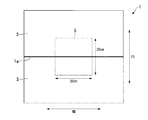
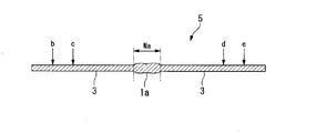
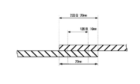
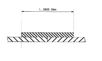
- the bonded body 1 is cut out into a square of 20 cm ⁇ 20 cm so that the bonding portion 1a for bonding the adjacent raw fabric 3 passes through the center of the TD at an arbitrary position of MD. Get The position of the joint 1a can be visually confirmed.
- the TD cross section is observed with an optical microscope at a position 10 cm inward from one outer edge of the MD of Sample 5, and as shown in FIG. 2, positions b, e and 4 cm at 2 cm inward from both outer edges of the TD cross section
- the thickness of the sample 5 is measured at the positions c and d (four places in total), and the average value of them is used as the thickness of the original fabric 3.
- the TD cross section is observed with an optical microscope at a position 10 cm inward from one outer edge of the MD of sample 5, and as shown in FIG.
- the width W a of (junction 1a) is determined.
- the width W a of the portion whose thickness is 101% or more of the thickness of the original 3 Ask for The average value of their widths W a is taken as the width of the joint 1 a.
- the tensile breaking strength of the joint portion is preferably 50% or more, more preferably 60% or more, and particularly preferably 80% or more of the tensile breaking strength of the raw fabric.
- the abrasion resistance of a junction and the dimensional stability are more excellent in tensile fracture strength of a junction being below the above-mentioned upper limit.
- the upper limit of the tensile breaking strength of the joint is not particularly limited, and may be 100%.
- the Rz on the surface of the bonding portion is preferably 15 ⁇ m or less, more preferably 5 ⁇ m or less, still more preferably 1 ⁇ m or less, and particularly preferably 0.7 ⁇ m or less.
- the abrasion resistance of a junction part is more excellent in Rz being below the above-mentioned upper limit. The smaller the Rz of the surface of the joint, the better, and it may be 0 ⁇ m.
- the raw fabric is made of a thermoplastic resin film.
- the thermoplastic resin film contains a thermoplastic resin.
- a thermoplastic resin amorphous resin and crystalline resin are mentioned. Examples of amorphous resins include polystyrene, polyvinyl chloride, polycarbonate, polymethyl methacrylate and the like.
- the crystalline resin may, for example, be a fluorine resin, a polyester resin or a polyolefin resin.
- ethylene-tetrafluoroethylene copolymer (hereinafter referred to as "ETFE"), perfluoro (alkyl vinyl ether) -tetrafluoroethylene copolymer (hereinafter referred to also as “PFA”), hexafluoropropylene -Tetrafluoroethylene copolymer (hereinafter also referred to as "FEP”), chlorotrifluoroethylene polymer (hereinafter referred to as "PCTFE”), vinyl fluoride polymer (hereinafter referred to also as "PVDF”) , Vinylidene fluoride polymer (hereinafter also referred to as "PVF”), vinylidene fluoride-hexafluoropropylene copolymer, tetrafluoroethylene-hexafluoropropylene-vinylidene fluoride copolymer, tetrafluoroethylene-propylene copolymer Combined, tetrafluoroethylene-prop
- polyester resin examples include polyethylene terephthalate resin, polybutylene terephthalate resin, and polylactic acid resin.
- polyolefin resin examples include polyethylene, ethylene- ⁇ -olefin copolymer, ethylene-vinyl acetate copolymer, ethylene-vinyl alcohol copolymer, polypropylene, ethylene-propylene copolymer and the like. Each of these polyolefin resins may further have other units.
- thermoplastic resin As a thermoplastic resin, a crystalline resin is preferable in that it is excellent in scratch resistance, chemical resistance and the like, and high strength can be easily obtained by stretching and the like. That is, it is preferable that a thermoplastic resin film is a film of crystalline resin. Among crystalline resins, fluorine resins are preferable in terms of excellent weather resistance and chemical resistance. That is, it is preferable that the thermoplastic resin film is a fluorine resin film.
- fluorine resins at least one selected from the group consisting of ETFE, PFA, FEP, PCTFE, PVDF and PVF is preferable in terms of excellent weatherability, specific gravity and cost, and from the group consisting of ETFE, PFA and FEP At least one selected is more preferable, and ETFE is particularly preferable.
- thermoplastic resin film may further contain other components other than the thermoplastic resin, as necessary.
- Other components include flame retardants, UV absorbers, UV blockers, fillers, pigments and the like.
- Rz of the surface of the thermoplastic resin film is typically 5 ⁇ m or less, but it is not limited to the above when embossing or the like is performed.
- the thickness of the thermoplastic resin film is typically 10 to 1,000 ⁇ m.
- the width of the thermoplastic resin film is typically 0.5 to 3 m.
- the root mean square height (hereinafter referred to as “root mean square height” of the surface undulation shape measured at a position 50 mm outward from the outer edge in the width direction of the joint portion joining adjacent raw materials of the joined body of the present invention (It is also described as “50 mm from the outer edge”) is 0.5 mm or less, preferably 0.45 mm or less, and particularly preferably 0.40 mm or less.
- the root mean square height (50 mm from the outer edge) is equal to or less than the upper limit value, the scratch resistance of the joined body is excellent.
- the “root mean square height of the surface undulation shape” is an index indicating the size of the wrinkles, and is measured by the following measurement method.
- the root mean square height (50 mm from the outer edge) becomes large.
- the root-mean-square height (50 mm from the outer edge) is 0 by setting the temperature measured by a thermocouple placed on the surface of the raw fabric at a position 50 mm outward from the outer edge in the width direction of the welding target area It can be less than .5 mm.
- FIG. 3 is a view schematically showing a surface undulation shape obtained by geometrically transforming pixel coordinates of a photographed image.
- root mean square height (1 mm from the outer edge) of the surface undulation shape measured at a position 1 mm outward from the outer edge of the joint in the width direction of the joint of the present invention.
- 0.5 mm or less is preferable and 0.45 mm or less is especially preferable.
- the root mean square height (1 mm from the outer edge) is preferably as small as possible, and may be 0 mm.
- the root mean square height (1 mm from the outer edge) tends to increase if the heat is applied to the area other than the welding target area of the raw material.
- the root-mean-square height (1 mm from the outer edge) is 0 by setting the temperature measured by a thermocouple placed on the surface of the raw fabric at a position 50 mm outward from the outer edge in the width direction of the welding target area It can be less than .5 mm.
- Root-mean-square height of surface undulation shape (hereinafter, also referred to as “root-mean-square height (50 mm from center)” of the bonded structure of the present invention measured at a position 50 mm outward from the center in the width direction of the bonding portion ) Is preferably 0.5 mm or less.
- the scratch resistance of the joined body is more excellent.
- the root mean square height (50 mm from the center) becomes large. Also, the wider the junction, the larger the root mean square height (50 mm from the center) tends to be.
- the temperature measured by a thermocouple placed on the surface of the raw fabric at a position 50 mm outward from the outer edge in the width direction of the region to be welded is 40 ° C. or less, and the width of the joint is 8 mm or less.
- the height (50 mm from the center) can be made 0.5 mm or less.
- 25 MPa or more is preferable, 35 MPa or more is more preferable, and 45 MPa or more is especially preferable. It can be used for the use by which the strength of a joined object is required as tensile rupture strength is more than the above-mentioned lower limit, for example, a film structure use.
- the upper limit of the tensile breaking strength of the joined body is not particularly limited, and is, for example, 60 MPa.
- the bonded body of the present invention can be produced by the method for producing a bonded body of the present invention described later.
- the width of the joint can be adjusted by the overlapping width of the two original rolls and the width of the target area to be heated and pressed. The larger the overlap width, the wider the joint.
- the overlapping width is smaller than the width of the target area, and the maximum width of the target area substantially matches the width of the joint.
- the overlapping width at the time of obtaining a bonded body having a width of 1 to 8 mm at the bonding portion is preferably 0 to 5 mm, and particularly preferably more than 0 mm and 5 mm or less.
- the method of producing the joined body of the present invention is not limited to this.
- the root mean square height of the surface undulation shape at a position of 50 mm on the outer side from the outer edge in the width direction of the bonded portion is 0.5 mm or less, it has excellent scratch resistance.
- the larger the wrinkles in the vicinity of the bonding portion the larger the variation in the degree of crystallization of the raw fabric in the vicinity of the bonding portion.
- the portion with low crystallinity is easily scratched, and the presence of such a portion lowers the scratch resistance of the bonded body.
- the scuff resistance of the joined body is reduced due to the large wrinkles and the possibility of rubbing against other members.
- the root mean square height of the surface undulation shape at the position is 0.5 mm or less, the variation of the crystallinity in the vicinity of the bonded portion is small, and the scratch easily occurs. There are few parts. In addition, because the swell is small, it is difficult to rub with other members. Therefore, it is thought that it is excellent in abrasion resistance.
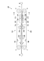
- FIG. 4 is a schematic configuration view of the welding device 100.
- FIG. 5 is a partial cross-sectional view showing a part of the IV-IV cross section in FIG.
- the welding apparatus 100 includes a pair of endless belts 10A and 10B and a pair of welds 20A and 20B.
- the endless band is a member in which the band is formed into an annular shape by joining end portions in the longitudinal direction.
- the pair of endless belts 10A and 10B are disposed vertically.
- the endless belts 10A and 10B are each rotatably supported in the first direction (the arrow X direction in FIG. 4) by the plurality of support rolls 11.
- the opposing portions of the pair of endless belts 10A and 10B that is, the portions of the endless belt 10A facing the endless belt 10B and the endless belt
- the portions of the strip 10B facing the endless strip 10A are arranged to travel forward. Traveling forward means traveling from the upstream side to the downstream side of the MD.
- traveling paths of two original rolls 3 are formed between the outer peripheral surfaces 10a and 10b of the opposing portions of the pair of endless belts 10A and 10B.
- the traveling path travels the two raw webs 3 with their widthwise ends overlapping or abutting each other.
- FIG. 5 shows an example in which the end portions in the width direction of two sheets of raw fabric 3 are overlapped and brought into contact with each other.
- the welding portion 20A is disposed inside the endless strip 10A at a position facing the traveling path.
- the welding unit 20A includes two heating units 21A and 23A (heating mechanisms), two cooling units 31A and 33A (first cooling mechanisms) disposed in the vicinity of the heating units 21A and 23A, and the heating units 21A and 23A. And a cooling unit 27A (second cooling mechanism) disposed on the downstream side of the pressing roll 25A.
- the heating unit 23A is disposed downstream of the heating unit 21A.
- the welding portion 20B is disposed inside the endless strip 10B at a position facing the traveling path.
- the welded portion 20B includes two heating units 21B and 23B (heating mechanisms), two cooling units 31B and 33B (first cooling mechanisms) disposed in the vicinity of the heating units 21B and 23B, and the heating units 21B and 23B. And a cooling unit 27B (second cooling mechanism) disposed on the downstream side of the pressing roll 25B.
- the heating unit 23B is disposed downstream of the heating unit 21B.
- the heating unit 21A and the heating unit 21B on the upstream side are disposed at opposing positions across the traveling path.
- the downstream side heating unit 23A and the heating unit 23B are disposed at opposing positions across the travel path. That is, two pairs of heating units 21A, 21B and 23A, 23B are provided in the middle of the traveling route along which the two original rolls travel, and the welding target regions of the two original rolls traveling along the traveling route are two stages from both sides. It can be heated.
- the four cooling units 31A, 31B, 33A, 33B are attached to the four heating units 21A, 21B, 23A, 23B, respectively, and other than the welding target areas of the two original rolls 3 traveling along the traveling path from each heating unit Heat transfer to the region of The pressing roll 25A and the pressing roll 25B are disposed at positions facing each other through the traveling path, and can press the welding target regions of the two upstream heated original sheets 3 traveling on the traveling path from both sides.
- the width of the pressure rolls 25A, 25B is equal to or less than the width of the endless strips 10A, 10B.
- the cooling unit 27A and the cooling unit 27B are disposed at opposing positions through the traveling path, and cool the welding target regions of the two heated and pressed original sheets traveling on the traveling path from both sides, It can be solidified.
- the cooling units 27A and 27B are, for example, water cooling plate type cooling units.
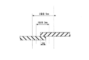
- FIG. 6 shows an example of endless belts that can be used as the endless belts 10A and 10B.
- the endless belt 10 shown in FIG. 6 includes an endless belt-like woven fabric layer 13 and a polytetrafluoroethylene (hereinafter also referred to as “PTFE”) layer 15 laminated on the outer peripheral surface of the woven fabric layer 13. .
- the PTFE layer 15 has a multilayer structure in which the PTFE coat layer 17 and the PTFE film layer 19 are laminated in order from the woven fabric layer 13 side.
- the Rz of the outer circumferential surface 10c of the endless strip 10, ie, the outer circumferential surface of the PTFE layer 15, is preferably 15 ⁇ m or less, more preferably 5 ⁇ m or less, still more preferably 1 ⁇ m or less, and particularly preferably 0.7 ⁇ m or less.
- the woven layer 13 has irregularities on the surface due to the fibers. Since the PTFE layer 15 is provided on the woven fabric layer 13, the outer peripheral surface 10c of the endless strip 10, that is, the surface in contact with the raw fabric 3 is flattened, and Rz is equal to or less than the upper limit.
- the width of the endless strip 10 is, for example, 1 to 10 cm.
- Rz of the outer peripheral surface 10c of the endless belt 10 that is, Rz of the outer peripheral surfaces 10a and 10b of the endless belts 10A and 10B is equal to or less than the upper limit
- the welding strength of the two original rolls 3 is excellent.
- the width of the welding target area that is, the width of the raw fabric welded portion (joint portion) where the raw fabrics are welded
- the tensile breaking strength of the raw fabric welded portion is 50% of the tensile breaking strength of the raw fabric 3. It can be more than%.
- the outer peripheral surfaces 10a and 10b of the endless belts 10A and 10B have the molten resin attached in the welding process, and the welding strength is rather reduced by the influence of the adhesive force. Since it is also possible to increase Rz is preferable.
- the width of the original welded portion is 1 to 8 mm, relatively the molten resin hardly adheres to the outer peripheral surfaces 10a and 10b, and the adhesion is also small.
- the attachment can also be suppressed by a cooling unit or the like. It is considered that the reduction of Rz effectively extends the overlapping portion of the raw fabric and also leads to the increase of the degree of crystallinity.
- glass fiber As a fiber which comprises the woven fabric layer 13, glass fiber, an aramid fiber, carbon fiber etc. are mentioned. These fibers may be used alone or in combination of two or more. Among the above, glass fiber is preferable in terms of excellent heat resistance and low cost.
- Examples of the type of weave of the woven fabric layer 13 include plain weave, twill weave, satin weave, and the like.
- the thickness of the woven fabric layer 13 is, for example, 10 to 100 ⁇ m.
- Rz of the surface of the woven fabric layer 13 is usually more than 15 ⁇ m and about 100 ⁇ m or less.
- the mass per unit area of the PTFE coat layer 17 (the applied amount of PTFE) is, for example, 50 to 150 g / m 2 .
- the thickness of the PTFE film layer 19 is preferably 10 to 200 ⁇ m, and particularly preferably 50 to 150 ⁇ m.
- the unevenness of the surface of the woven fabric layer 13 is hardly reflected on the outer peripheral surface of the PTFE film layer 19 when the thickness of the PTFE film layer 19 is not less than the lower limit, and the Rz of the outer peripheral surface 10c of the endless strip 10 is the upper limit. It is easy to become below.
- Rz of the surface of the original welded portion becomes equal to or less than the upper limit, and the abrasion resistance and tensile breaking strength of the original welded portion are excellent.
- the thickness of the PTFE film layer 19 is equal to or less than the upper limit value, the handling property is excellent.
- a PTFE dispersion containing PTFE and a dispersion medium is applied to the outer peripheral surface of an endless belt-like woven fabric (woven fabric layer 13) and dried to form a PTFE coated layer 17. And a method of laminating a PTFE film on the PTFE coat layer 17.
- the endless belt-like woven fabric is obtained by joining one end and the other end in the lengthwise direction of the belt-like woven fabric into an annular shape. Bonding of the woven fabric can be carried out by a conventional method. An existing endless belt-like woven fabric may be used.
- the PTFE dispersion may be a commercially available product.
- the drying method is, for example, heating at the boiling point or more of the dispersion medium.
- the Rz of the surface of the PTFE film is preferably 15 ⁇ m or less, and the more preferable range is as described above.
- the preferred thickness of the PTFE film is similar to the preferred thickness of the PTFE film layer 19. Examples of the method of laminating the PTFE film include thermal lamination, bonding using an adhesive layer, and the like.
- the PTFE coat layer 17 may be formed before making the belt-like woven fabric into an endless belt shape.
- the endless band used in the present invention is not limited to the endless band 10.
- the PTFE layer 15 may be composed of only the PTFE film layer 19 or may be composed of only the PTFE coat layer 17.
- the PTFE coat layer 17 may be provided on both sides of the woven fabric layer 13.
- a PTFE film layer 19 may be provided on both sides of the woven fabric layer 13.
- a part of the PTFE is impregnated into the woven fabric, and the surface of the PTFE coat layer 17 is roughened.
- Rz can be made equal to or less than the upper limit with only the PTFE coating layer 17, but the process is complicated and expensive. Therefore, the method of laminating a PTFE film is simple and preferable.
- the PTFE film may be laminated directly on the outer peripheral surface of the woven fabric layer 13 without forming the PTFE coat layer 17.
- the endless belt-like woven fabric layer 13 may be used as an endless belt as it is.
- the heating unit 21A is a heating plate type heating unit (heating plate type heating mechanism), and includes a heating plate 29 and a heater (not shown) for heating the heating plate.
- the heat plate 29 has a flat base portion 29a and a convex portion 29b protruding from the base portion 29a toward the endless strip 10A, and has a T-shaped TD cross section.
- the convex portion 29b has a distal end surface 29c, and a first side surface 29d and a second side surface 29e extending in the direction of the base 29a from each of the TD ends of the distal end surface 29c.
- the heat plate 29 is disposed with the tip end face 29c facing the traveling path.
- the end surface 29c contacts the inner peripheral surface of the endless belt 10A, and when the heating plate 29 is heated to an arbitrary temperature by the heater, the portion in contact with the end surface 29c of the endless belt 10A is heated, By this, the welding target area of the raw fabric 3 traveling on the traveling route is heated.
- Width of the end surface 29c is the same as the width W 1 of the two raw 3 of the welding target area.
- the width W 1 of the welding target area is typically wide relative to the overlapping width W 2 of the two original webs 3. Accordingly, the width in the TD of the end face 29c is also typically wide relative to the overlapping width W2 of the two original rolls 3.
- the other heating units 21B, 23A, and 23B are also hot plate type heating units, and have the same configuration as that of the heating unit 21A.
- the width of the end surface 29c of the upstream heating units 21A and 21B and the width of the end surface 29c of the downstream heating units 23A and 23B may be the same or different.
- the width of the end surface 29c of the heating units 21A and 21B may be narrower than the width of the end surface 29c of the heating units 23A and 23B.
- the widest width among the width of the end surface 29c of the heating units 21A and 21B and the width of the end surface 29c of the heating units 23A and 23B is the width of the original welded portion of the obtained bonded body.
- the cooling unit 31A is a water cooling plate type cooling unit (water cooling mechanism) including a pair of water cooling plates 35 and 37 disposed on both sides of the heating unit 21A in the TD.
- One water-cooling plate 35 has an L-shaped TD cross section, and is disposed on the first side face 29 d side (left side in FIG. 5) of the convex portion 29 b of the heat plate 29 with a gap between the water plate and the heat plate 29.
- the water cooling plate 35 covers the surface of the base portion 29a on the endless belt 10A side and the side surface of the base 29a on the first side surface 29d side and the first side surface 29d.
- the other water cooling plate 37 has a TD cross section that is an L-shape symmetrical with the water cooling plate 35, and on the second side surface 29e side (right side in FIG. 5) of the convex portion 29b of the heating plate 29 Spaced apart.
- the water cooling plate 37 covers the surface of the base portion 29a on the endless belt 10A side and the side surface of the base 29a on the second side surface 29e side and the second side surface 29e.
- the water cooling plates 35 and 37 for example, those having a configuration using a chiller can be mentioned.
- the cooling unit 31A by cooling the atmosphere between the heat plate 29 and the endless strip 10A with the water cooling plates 35, 37, the heat radiated from the surface other than the tip end surface 29c of the heat plate 29 is It can be transmitted to a region other than the welding target region of the raw fabric 3 and can be suppressed from increasing the temperature of the raw fabric 3.
- the water cooling plates 35 and 37 are arranged such that the tip end portions of the convex portions 29b of the heat plate 29 project to the endless belt 10A side more than the surfaces 35a and 37a of the water cooling plates 35 and 37 on the endless belt 10A side. Be done.
- the distance between the first side surface 29d of the heat plate 29 and the water cooling plates 35 and 37 is preferably 0.1 to 10 mm, and particularly preferably 0.5 to 5 mm.
- the difference between the surfaces 35a, 37a of the water cooling plates 35, 37 on the endless belt 10A side and the end surface 29c of the convex portion 29b is preferably 0.1 to 10 mm, particularly preferably 0.5 to 5 mm.
- the difference is less than the upper limit value, the effect of suppressing heat propagation to a region other than the welding target region is more excellent, and when it is more than the lower limit value, physical contact with the endless strip is avoided. The wear of the endless band is suppressed and the durability is excellent.
- the other cooling units 31B, 33A, 33B also have the same configuration as the cooling unit 31A.
- the pair of endless strip-shaped members 10A and 10B is rotated so that the portions facing each other travel forward.
- the two raw materials 3 made of a thermoplastic resin film face each other of the pair of endless belts 10A and 10B.
- a pair of heating units disposed on the upper and lower sides of the traveling route, including a portion where two original rolls 3 contact each other while traveling along the traveling route formed between the outer peripheral surfaces 10a and 10b of the part At both 21A and 21B, heating is performed from both sides via the endless belts 10A and 10B to fuse them (first heating step).
- the regions to be welded are heated and fused from both sides via the endless belts 10A and 10B by the pair of heating units 23A and 23B disposed above and below the traveling path (second heating step).
- the regions to be welded are pressed from both sides by pressure rolls 25A and 25B arranged above and below the traveling path, and pressed (pressure step).
- the regions to be welded are cooled from both sides by the cooling units 27A and 27B disposed above and below the traveling path and solidified (solidification step).
- the first heating step heat propagation from the heating units 21A and 21B to regions other than the welding target region of the two original rolls 3 (hereinafter, also referred to as "other regions") by the cooling units 31A and 31B.
- the temperature measured by a thermocouple disposed on the surface of the original 3 at a position 50 mm outward from the outer edge in the width direction of the welding target area is set to 40 ° C. or less.
- heat propagation from the heating units 23A and 23B to the other area of the two original rolls 3 is suppressed by the cooling units 33A and 33B, and the outer edge of the welding target area in the width direction is outward
- the temperature measured by the thermocouple placed on the surface of the raw fabric 3 at the position of 50 mm is 40 ° C. or less.
- the above-mentioned steps are repeated using the obtained conjugate in place of either one or both of the two base rolls 3.
- a joined body in which three or more original rolls 3 are joined is obtained.
- the obtained bonded body may be subjected to treatments such as corona treatment and dripping treatment, if necessary.
- the area to be welded after solidification is also referred to as an original welded area.
- the original welded portion may be a joint.
- at least a part of the raw fabric welded portion has a thickness of 101% or more of the thickness of the raw fabric, that is, a joint .
- the thickness of the raw fabric welded portion is less than 100% of the thickness of the raw fabric.
- the rotation speed of the endless belts 10A and 10B is, for example, 0.5 to 10 m / min, preferably 1.0 to 9.0 m / min, and more preferably Is 2.0 to 8.0 m / min. If it is in the said range, there exists a tendency for the tensile breaking strength of a raw material welding part to be excellent.
- the overlapping width of the two raw sheets is preferably 0 to 40 mm, more preferably 0 to 8 mm, still more preferably 0 mm to 8 mm or less, particularly preferably 1 to 7 mm, and most preferably 1 to 3 mm.
- the overlapping width of 0 mm indicates that the two raw webs are caused to travel while the ends in the width direction are in contact with each other. That the overlapping width is more than 0 mm indicates that the two raw webs are caused to travel with the widthwise end portions overlapped with each other.
- the overlapping width is equal to or less than the upper limit value, the width of the raw wire welded portion (joined portion) is narrow, so the amount of dimensional change of the raw wire welded portion is relatively small, and wrinkles in the post process hardly occur.
- the size is 8 mm or less, even if the original welded portion is damaged during transportation or fixing to the frame, the number of scratches on the original welded portion is relatively small because the width of the original welded portion is narrow. The wound is inconspicuous. Therefore, the appearance of the bonded body is unlikely to deteriorate, and the yield is also less likely to decrease.
- the overlapping width is 1 mm or more, the tensile breaking strength of the joint is excellent.
- the heating temperature in the first heating step and the second heating step is preferably (T-20) ° C. or more and (T + 20) ° C. or less (T ⁇ 10) ° C. or more and (T + 10) ° C. or less are more preferable, and (T ⁇ 5) ° C. or more and (T + 5) ° C. or less are particularly preferable.
- the pressure at the time of pressing in the first heating step and the second heating step is not particularly limited, and may be, for example, 0.1 to 0.5 MPa.
- the heating temperature and pressure in each heating step may be the same or different.
- the temperature measured by the thermocouple disposed on the surface of the raw fabric 3 at a position 50 mm outward from the outer edge in the width direction of the welding target regions of the two raw fabrics 3 is 40 ° C. or less, preferably 35 ° C. or less, particularly preferably 30 ° C. or less. If the temperature is equal to or less than the upper limit value, the tensile breaking strength of the raw welded portion can be 50% or more of the tensile breaking strength of the raw fabric even if the overlapping width of the two raw fabrics 3 is narrow.
- the lower limit of the temperature is not particularly limited, and is, for example, 10 ° C.
- the pressure at the time of pressing in the pressing step is preferably 0.1 to 5 MPa, and particularly preferably 0.5 to 2.5 MPa.
- the temperature at the time of pressing in the pressing step that is, the surface temperature of the pressing rolls 25A and 25B is not particularly limited, and is 25 ° C., for example.
- the cooling in the solidification step is performed so that the temperature measured by the thermocouple disposed on the surface of the raw fabric 3 at a position 50 mm outward from the outer edge in the width direction of the welding target area after cooling becomes 10 to 40 ° C.
- the reaction is preferably carried out at 15 to 35.degree. C., particularly preferably at 20 to 30.degree.
- the raw film 3 is placed 50 mm outward from the outer edge of the width direction of the welding target area of the two raw materials 3 Since the ambient temperature in the vicinity, which is measured by the thermocouple disposed on the surface of the above, is made equal to or lower than the upper limit value, the occurrence of wrinkles can be suppressed.
- the outer circumferential surface of the endless belts 10A and 10B is pressed against the surface of the heated welding target area.
- the temperature measured by the thermocouple disposed on the surface of the raw fabric 3 at a position 50 mm outward from the outer edge in the width direction of the target region is set to the upper limit value or less. Heat propagation to the other region of the original fabric 3 is sufficiently suppressed, and orientation relaxation in the other region is suppressed. Therefore, a bonded body with few wrinkles is obtained. In addition, variations in the degree of crystallinity in the vicinity of the bonding portion can also be suppressed.
- the raw fabric 3 When the target area is at a high temperature by heating, the raw fabric 3 is easily attached to the outer peripheral surface of the endless belts 10A and 10B. When this adhesive force is high, a part of the raw fabric 3 adheres to the endless belts 10A and 10B, so that a part of the raw fabric 3 is dropped to cause unevenness, or peeling occurs in a part of the joint. It becomes a cause. In addition, the raw fabric 3 is locally pulled and is likely to be distorted, which may cause wrinkles. In the above manufacturing method, when the welding target area is narrow, for example, 8 mm or less, the adhesion generated between the outer peripheral surface of the endless belts 10A and 10B and the raw fabric 3 can be suppressed low.
- the raw fabric 3 is less likely to adhere to the endless belts 10A and 10B.
- wrinkles are less likely to occur.
- the manufacturing method of the joined body of the present invention is not limited to the method using the welding device 100 of the illustrated example.
- the water cooling plate type cooling mechanism cooling units 31A, 31B, 33A, 33B
- another water cooling mechanism may be used.
- a wind cooling mechanism may be used.
- the heat propagation to the other area can be suppressed by sending an air flow of an arbitrary temperature to the atmosphere between the heating units 21A, 21B, 23A, 23B and the endless belts 10A, 10B.
- welding part 20A, 20B was provided with two heating mechanisms (heating unit 21A, 21B, heating unit 23A, 23B), respectively and the example which heats a welding object area
- the heating mechanism may be one or three or more, and the region to be welded may be heated in one or more stages.
- Example 1 is an example, and examples 2 to 5 are comparative examples. The evaluation methods and materials used in each example are shown below.
- Area camera (resolution 0.08 mm, shutter speed 10 ms, F-number F16) installed at a position 250 mm outward in the width direction and 25 mm upward in the height direction from the irradiation unit (the part irradiated with the laser light of the assembly)
- the image projected on the irradiation unit was taken at a focal distance of 55 mm, horizontally in the widthwise direction of the joint, with the irradiation unit as the focus position.
- the wave shape of the image taken was geometrically transformed to obtain the surface wave shape. In geometric transformation, each of 710 pixel coordinates was converted into mm coordinates by 0.08 (resolution).
- the standard deviation (mm) in the height direction is calculated by the above equation 1
- the root mean square height was taken.
- the root-mean-square height was determined in the same manner as described above for each of the positions 1 mm outward from the outer edge in the width direction of the joint of the bonded body and 50 mm outward from the center in the width direction of the joint. In addition, when welding itself was impossible, it described as "x.”
- ETFE film 100 ⁇ m thick ETFE film (melting point: about 270 ° C.).
- Endless strip 1 Endless strip having the configuration shown in FIG. 6 (woven fabric layer: woven glass fiber, plain weave, thickness of PTFE film layer: 100 ⁇ m, Rz of outer peripheral surface: 0.63 ⁇ m, arithmetic average roughness of outer peripheral surface) Ra: 0.1 ⁇ m).
- Example 1 Using the welding apparatus 100 having the configuration shown in FIGS. 4 to 5, a joined body was manufactured in the following procedure.
- the endless strip 1 was used as the endless strips 10A and 10B.
- the width of the tip surface of the first-stage heating units 21A and 21B is 3 mm, and the width of the tip surface of the second-stage heating units 23A and 23B is 5 mm.
- the end portions of two ETFE films (250 mm in width) are overlapped at an overlapping width of 1 mm, and the outer peripheral surface 10a of opposing portions of a pair of endless endless belts 10A and 10B is rotated.
- the traveling route formed between 10b was run.
- the heating unit 21A, 21B in the first stage and the heating unit 23A, 23B in the second stage sequentially heat from both sides, press from both sides with the pressure rolls 25A, 25B, and cool from both sides in the cooling units 27A, 27B. And obtained a conjugate.
- the cooling units 31A, 31B, 33A, 33B suppressed the heat propagation from each heating unit to the other region of the two original rolls.
- the rotation speed of the endless belts 10A and 10B that is, the transport speed of the raw fabric was 2 m / min, 5 m / min, or 8 m / min.
- the heating conditions in the heating units 21A and 21B were a heating temperature of 270 ° C., 275 ° C. or 280 ° C., and a pressure of 0 MPa.
- the heating conditions in the heating units 23A and 23B were the same as the heating units 21A and 21B except that the pressure was 0.1 MPa.
- the pressing conditions of the pressing rolls 25A and 25B were a temperature of 25 ° C. and a pressure of 2.5 MPa. In the cooling by the cooling units 27A and 27B, the surface temperature of the target area was set to 30.degree.
- the cooling by the cooling units 31A, 31B, 33A, 33B is a thermoelectric element disposed on the surface of the raw fabric 3 at a position 50 mm outward from the outer edge in the width direction of the target area at the time of heating in the first heating step and the second heating step.
- the temperature measured by the pair was made to be the temperature shown in Table 1.
- a thermocouple a data logger GL220 manufactured by GLARHTEC was used.
- the width of the bonded portion of the obtained bonded body was 3.9 mm, and the thickness of the bonded portion was 120 ⁇ m (120% of the original thickness).
- Example 2 In the welding apparatus 100, the cooling units 31A, 31B, 33A, and 33B were removed, and the heat propagation from each heating unit to the other area of the two original rolls was not suppressed, the first-stage heating units 21A and 21B
- the width of the tip surface (the width of the first heating area) is 25 mm
- the width of the tip surface of the second heating unit 23A, 23B (the width of the second heating area) is 30 mm, and As shown in FIG.
- Example 8 the end of an ETFE film (250 mm wide) is overlapped at an overlapping width of 20 mm, and an ETFE film of 30 mm wide is overlapped on the overlapping portion so as to straddle the overlapping portion, A joint was manufactured in the same manner as Example 1 except that the vehicle was run.
- the width of the bonded portion of the obtained bonded body was 28.6 mm, and the thickness of the bonded portion was 280 ⁇ m (280% of the original thickness).
- Example 3 The width of the tip surface of the first stage heating units 21A and 21B (the width of the area heated to the first time) is 10 mm, the width of the tip surface of the second stage heating units 23A and 23B (the width of the area heated to the second time ) was 20 mm, and as shown in FIG. 9, a joined body was produced in the same manner as in Example 2 except that an ETFE film of 30 mm in width was not superposed on the overlapping portion of two ETFE films.
- the width of the bonded portion of the obtained bonded body was 18.9 mm, and the thickness of the bonded portion was 170 ⁇ m (170% of the original thickness).
- Example 4 The width of the tip surface of the first-stage heating unit 21A, 21B (the width of the area to be heated at the first time) and the width of the tip surface of the second-stage heating unit 23A, 23B (the width of the area to be heated at the second time)
- a bonded body was manufactured in the same manner as in Example 2 except that the sizes were respectively 30 mm, and as shown in FIG. 10, the end portions of the two ETFE films were butted without overlapping.
- the 30 mm wide ETFE film was placed so that the center position in the width direction coincided with the butting position of the two ETFE films.
- the width of the bonded portion of the obtained bonded body was 29.1 mm, and the thickness of the bonded portion was 180 ⁇ m (180% of the original thickness).
- Example 5 In the welding apparatus 100, the joined body is removed in the same manner as in Example 1 except that the cooling units 31A, 31B, 33A, 33B are removed, and the heat propagation from each heating unit to the other regions of the two original rolls is not suppressed. Manufactured.
- the width of the bonded portion of the obtained bonded body was 3.9 mm, and the thickness of the bonded portion was 130 ⁇ m (130% of the original thickness).
- the root mean square height of the surface undulation shape at positions 50 mm and 1 mm outward from the widthwise outer edge of the joint of the joined body obtained in Examples 1 to 5 and 50 mm outside from the center of the widthwise joint of the joint Is shown in Table 1.
- the bonded structure of Example 1 has a root mean square height of 0.5 mm at a position 50 mm and 1 mm outward from the outer edge in the width direction of the joint and 50 mm outward from the center in the width direction of the joint. It was below and there were few wrinkles.
- the joined body of Examples 2 to 5 in which the temperature measured by the thermocouple disposed on the surface of the raw fabric at a position 50 mm outward from the outer edge in the width direction of the target area during heating of the target area was over 40 ° C.
- the root mean square height at a position of 50 mm outside the widthwise outer edge of the joint all exceeded 0.5 mm, and the wrinkles were large.
- the conjugate of the present invention can be used as a film for a membrane structure (for example, an outer covering film for a membrane structure) or as an agricultural film (for example, a house coating film for agriculture).
- the membrane structure is a structure such as a roof using a film, an outer wall, and a facility.
- the facilities include sports facilities (pools, gymnasiums, tennis courts, soccer fields, etc.), warehouses, gathering halls, exhibition halls, horticultural facilities (gardening houses, farming houses, etc.).
- the entire contents of the specification, claims, abstract and drawing of Japanese Patent Application No. 2017-226590 filed on November 27, 2017 are cited herein as the disclosure of the specification of the present invention, It is what it takes.
- W 1 assembly 1a joints, 3 raw, 5 samples, W a junction width, 10, 10A, 10B endless strip, 10a, 10b, the outer peripheral surface of 10c the endless strip, 11 the support rolls, 20A, 20B Welded part, 21A, 21B, 23A, 23B heating unit (heating mechanism), 25A, 25B pressing roll, 27A, 27B cooling unit (second cooling mechanism), 29 heating plate, 29a base, 29b convex part, 29c front end face , 29d first aspect, 29e second aspect, W 1 be welded region having a width, W 2 overlapping width, 30 cooling mechanism, 31A, 31B, 33A, 33B cooling unit (first cooling mechanism), 35 and 37 water-cooled plate , 100 welding equipment
Landscapes
- Engineering & Computer Science (AREA)
- Mechanical Engineering (AREA)
- Lining Or Joining Of Plastics Or The Like (AREA)
- Laminated Bodies (AREA)
Abstract
L'invention concerne un corps assemblé qui présente une résistance remarquable aux rayures. Ce corps assemblé, qui est obtenu par assemblage d'au moins deux feuilles d'une matière première comprenant un film de résine thermoplastique, est caractérisé en ce que la hauteur moyenne quadratique de la forme d'onde de la surface mesurée en une position située à 50 mm vers l'extérieur depuis le bord extérieur d'une partie assemblée dans la direction de la largeur, ladite partie assemblée étant située à l'endroit où des feuilles adjacentes de la matière première sont assemblées, est de 0,5 mm ou moins.
Priority Applications (1)
| Application Number | Priority Date | Filing Date | Title |
|---|---|---|---|
| JP2019555381A JPWO2019103123A1 (ja) | 2017-11-27 | 2018-11-22 | 接合体、その製造方法及び溶着装置 |
Applications Claiming Priority (2)
| Application Number | Priority Date | Filing Date | Title |
|---|---|---|---|
| JP2017226590 | 2017-11-27 | ||
| JP2017-226590 | 2017-11-27 |
Publications (1)
| Publication Number | Publication Date |
|---|---|
| WO2019103123A1 true WO2019103123A1 (fr) | 2019-05-31 |
Family
ID=66630647
Family Applications (1)
| Application Number | Title | Priority Date | Filing Date |
|---|---|---|---|
| PCT/JP2018/043276 Ceased WO2019103123A1 (fr) | 2017-11-27 | 2018-11-22 | Corps assemblé, procédé pour sa production et dispositif de soudage |
Country Status (2)
| Country | Link |
|---|---|
| JP (1) | JPWO2019103123A1 (fr) |
| WO (1) | WO2019103123A1 (fr) |
Cited By (1)
| Publication number | Priority date | Publication date | Assignee | Title |
|---|---|---|---|---|
| DE102022101223A1 (de) | 2022-01-19 | 2023-07-20 | Vector Foiltec Gmbh | Verfahren zum Verschweißen einer Architektur-Folie entlang einer Schweißnaht sowie Architektur-Folie |
Citations (5)
| Publication number | Priority date | Publication date | Assignee | Title |
|---|---|---|---|---|
| JPH058298A (ja) * | 1990-12-20 | 1993-01-19 | Nippon Valqua Ind Ltd | 熱可塑性樹脂の融着方法及び融着装置 |
| JPH06883A (ja) * | 1992-06-23 | 1994-01-11 | Kuinraito Denshi Seiko Kk | 合成樹脂シートの熱板式連続溶着装置 |
| JPH0634091Y2 (ja) * | 1990-08-02 | 1994-09-07 | 三ツ星ベルト株式会社 | 熱可塑性樹脂ベルト用ジョイントプレス |
| JP2005212311A (ja) * | 2004-01-30 | 2005-08-11 | Hagihara Industries Inc | 熱可塑性樹脂シートの接合方法 |
| JP2010120224A (ja) * | 2008-11-18 | 2010-06-03 | C I Kasei Co Ltd | シート接合体の製造方法 |
-
2018
- 2018-11-22 JP JP2019555381A patent/JPWO2019103123A1/ja active Pending
- 2018-11-22 WO PCT/JP2018/043276 patent/WO2019103123A1/fr not_active Ceased
Patent Citations (5)
| Publication number | Priority date | Publication date | Assignee | Title |
|---|---|---|---|---|
| JPH0634091Y2 (ja) * | 1990-08-02 | 1994-09-07 | 三ツ星ベルト株式会社 | 熱可塑性樹脂ベルト用ジョイントプレス |
| JPH058298A (ja) * | 1990-12-20 | 1993-01-19 | Nippon Valqua Ind Ltd | 熱可塑性樹脂の融着方法及び融着装置 |
| JPH06883A (ja) * | 1992-06-23 | 1994-01-11 | Kuinraito Denshi Seiko Kk | 合成樹脂シートの熱板式連続溶着装置 |
| JP2005212311A (ja) * | 2004-01-30 | 2005-08-11 | Hagihara Industries Inc | 熱可塑性樹脂シートの接合方法 |
| JP2010120224A (ja) * | 2008-11-18 | 2010-06-03 | C I Kasei Co Ltd | シート接合体の製造方法 |
Cited By (2)
| Publication number | Priority date | Publication date | Assignee | Title |
|---|---|---|---|---|
| DE102022101223A1 (de) | 2022-01-19 | 2023-07-20 | Vector Foiltec Gmbh | Verfahren zum Verschweißen einer Architektur-Folie entlang einer Schweißnaht sowie Architektur-Folie |
| WO2023138739A1 (fr) | 2022-01-19 | 2023-07-27 | Vector Foiltec Gmbh | Procédé de soudage d'un film d'architecture le long d'un cordon de soudure et film d'architecture |
Also Published As
| Publication number | Publication date |
|---|---|
| JPWO2019103123A1 (ja) | 2020-12-03 |
Similar Documents
| Publication | Publication Date | Title |
|---|---|---|
| JP5532182B1 (ja) | 透明性に優れたフッ素樹脂フィルム | |
| TWI607858B (zh) | 滾花裝置及方法以及膜卷製造方法 | |
| US20140087147A1 (en) | Self-corrugating laminates and methods of making them | |
| WO2019103123A1 (fr) | Corps assemblé, procédé pour sa production et dispositif de soudage | |
| JP5453134B2 (ja) | 網状体 | |
| JP4802389B2 (ja) | プラスチック中空板、その製造方法および製造装置 | |
| WO2016031930A1 (fr) | Feuille copolymere d'ethylene-tetrafluoroethylene et procede de production de celle-ci | |
| US6776935B2 (en) | Continuous process for making glittering cube corner sheeting | |
| US20140087145A1 (en) | Self-corrugating laminates and methods of making them | |
| WO2019103117A1 (fr) | Corps assemblé, son procédé de production, dispositif de soudage et corps en forme de courroie sans fin | |
| EP2271492A2 (fr) | Stratification continue d'un film de poly(méthacrylate de méthyle) (pmma) dans la fabrication d'une lentille de fresnel | |
| US10112370B2 (en) | Multilayer shrink film made of polyester with improved processing properties | |
| EP1486316B1 (fr) | Procede de liaison de films de fluororesine | |
| US20020098371A1 (en) | Ethylene-tetrafluoroethylene and tetrafluoroethylene-hexafluoropropylene copolymer films excellent in light transparency | |
| TW201031513A (en) | Method for producing surface treated fluororesin film | |
| US20140048202A1 (en) | Spiral cut liquid adhesive laminated film | |
| JP2005212311A (ja) | 熱可塑性樹脂シートの接合方法 | |
| JP3392760B2 (ja) | 耐薬品性シートの製造方法 | |
| WO2012169394A1 (fr) | Corps de maillage et procédé pour sa fabrication | |
| JP6095447B2 (ja) | 中空構造板の製造方法及び中空構造板 | |
| JP6022184B2 (ja) | 中空構造板の製造方法 | |
| JP4273827B2 (ja) | 熱可塑性樹脂フィルムの製造方法および熱可塑性樹脂フィルム | |
| JP5255689B2 (ja) | ポリオレフィン系樹脂織成シート | |
| JPS584608B2 (ja) | 加熱収縮性被覆用シ−トの製造方法 | |
| JPH06155579A (ja) | 熱圧着ラミネート方法 |
Legal Events
| Date | Code | Title | Description |
|---|---|---|---|
| 121 | Ep: the epo has been informed by wipo that ep was designated in this application |
Ref document number: 18882061 Country of ref document: EP Kind code of ref document: A1 |
|
| ENP | Entry into the national phase |
Ref document number: 2019555381 Country of ref document: JP Kind code of ref document: A |
|
| NENP | Non-entry into the national phase |
Ref country code: DE |
|
| 122 | Ep: pct application non-entry in european phase |
Ref document number: 18882061 Country of ref document: EP Kind code of ref document: A1 |