WO2019105353A1 - Cartouche de traitement - Google Patents
Cartouche de traitement Download PDFInfo
- Publication number
- WO2019105353A1 WO2019105353A1 PCT/CN2018/117774 CN2018117774W WO2019105353A1 WO 2019105353 A1 WO2019105353 A1 WO 2019105353A1 CN 2018117774 W CN2018117774 W CN 2018117774W WO 2019105353 A1 WO2019105353 A1 WO 2019105353A1
- Authority
- WO
- WIPO (PCT)
- Prior art keywords
- power receiving
- main body
- drive shaft
- receiving portion
- body portion
- Prior art date
- Legal status (The legal status is an assumption and is not a legal conclusion. Google has not performed a legal analysis and makes no representation as to the accuracy of the status listed.)
- Ceased
Links
Images


Classifications
-
- G—PHYSICS
- G03—PHOTOGRAPHY; CINEMATOGRAPHY; ANALOGOUS TECHNIQUES USING WAVES OTHER THAN OPTICAL WAVES; ELECTROGRAPHY; HOLOGRAPHY
- G03G—ELECTROGRAPHY; ELECTROPHOTOGRAPHY; MAGNETOGRAPHY
- G03G21/00—Arrangements not provided for by groups G03G13/00 - G03G19/00, e.g. cleaning, elimination of residual charge
- G03G21/16—Mechanical means for facilitating the maintenance of the apparatus, e.g. modular arrangements
- G03G21/18—Mechanical means for facilitating the maintenance of the apparatus, e.g. modular arrangements using a processing cartridge, whereby the process cartridge comprises at least two image processing means in a single unit
- G03G21/1839—Means for handling the process cartridge in the apparatus body
- G03G21/1857—Means for handling the process cartridge in the apparatus body for transmitting mechanical drive power to the process cartridge, drive mechanisms, gears, couplings, braking mechanisms
-
- G—PHYSICS
- G03—PHOTOGRAPHY; CINEMATOGRAPHY; ANALOGOUS TECHNIQUES USING WAVES OTHER THAN OPTICAL WAVES; ELECTROGRAPHY; HOLOGRAPHY
- G03G—ELECTROGRAPHY; ELECTROPHOTOGRAPHY; MAGNETOGRAPHY
- G03G21/00—Arrangements not provided for by groups G03G13/00 - G03G19/00, e.g. cleaning, elimination of residual charge
- G03G21/16—Mechanical means for facilitating the maintenance of the apparatus, e.g. modular arrangements
- G03G21/1642—Mechanical means for facilitating the maintenance of the apparatus, e.g. modular arrangements for connecting the different parts of the apparatus
- G03G21/1647—Mechanical connection means
-
- G—PHYSICS
- G03—PHOTOGRAPHY; CINEMATOGRAPHY; ANALOGOUS TECHNIQUES USING WAVES OTHER THAN OPTICAL WAVES; ELECTROGRAPHY; HOLOGRAPHY
- G03G—ELECTROGRAPHY; ELECTROPHOTOGRAPHY; MAGNETOGRAPHY
- G03G2221/00—Processes not provided for by group G03G2215/00, e.g. cleaning or residual charge elimination
- G03G2221/16—Mechanical means for facilitating the maintenance of the apparatus, e.g. modular arrangements and complete machine concepts
- G03G2221/1651—Mechanical means for facilitating the maintenance of the apparatus, e.g. modular arrangements and complete machine concepts for connecting the different parts
- G03G2221/1657—Mechanical means for facilitating the maintenance of the apparatus, e.g. modular arrangements and complete machine concepts for connecting the different parts transmitting mechanical drive power
Definitions
- the present invention relates to a process cartridge for use in an image forming apparatus.
- the process cartridge is a cartridge detachably incorporated in an image forming apparatus, and the cartridge as an integral unit includes at least one electrophotographic photosensitive member and at least a processor such as a charger, a developer, a cleaner, or the like One. Since the process cartridge is detachably mounted with respect to the image forming apparatus main body, maintenance of the image forming apparatus is facilitated.
- An image forming apparatus using an electrophotographic image forming apparatus works by selectively exposing an electrophotographic photosensitive member uniformly charged by a light of an image forming apparatus to form an electrostatic latent image, which is toned by a developing device The toner is developed into a toner image, and the formed toner image is transferred onto a recording medium by a transfer device to form an image on the recording material.
- Taiwan Patent Publication No. TW201633019A discloses a process cartridge including a drive assembly that can drive rotation of a photosensitive drum, the drive assembly having a hub and power receiving connection with the hub through a deformable connection
- a drive shaft is disposed, and the drive shaft is circumferentially disposed with a recess engageable with the power receiving portion, and the front end of the drive shaft is directly squeezed when the process cartridge is mounted in the image forming apparatus
- the receiving portion deforms the connecting portion and passes over the power receiving portion such that the power receiving portion finally engages with the concave portion to realize transmission of the driving force.
- the above-described driving assembly is connected to the hub and the power receiving portion by only relying on a thin deformable connecting portion, which causes the power receiving portion to damage the connecting portion when transmitting the driving force to the hub, resulting in failure to transmit the driving force.
- the thin deformable connecting portion needs to add a metal material during the molding process to strengthen the torsional strength that the driving assembly can withstand, and the molding process is complicated, resulting in an increase in the production cost of the driving assembly.
- a process cartridge detachably mounted in an image forming apparatus including a drive shaft provided with a recess, the drive shaft having a closed front end, and the process cartridge comprising:
- the coupling member includes a body portion and a power receiving portion configured to enter the recess and receive a rotational driving force from the drive shaft,
- the coupling member further includes a support portion that supports the power receiving portion, the support portion non-elastically supporting the power receiving portion.
- the power receiving portion is immovable in a radial direction of the main body portion with respect to the main body portion.
- the power receiving portion is configured as at least one protruding portion that protrudes radially inward of the main body portion.
- the main body portion is provided with a support portion supporting the power receiving portion, the support portion is configured to fixedly support the power receiving portion, and the support portion extends in a circumferential direction of the main body portion
- the arc length is larger than an arc length of the power receiving portion extending in the circumferential direction of the main body portion.
- the urging portions are disposed in at least two, and at least two of the urging portions are disposed to be asymmetrically arranged in a circumferential direction of the main body portion.
- an elastic member is disposed between the pressing portion and the main body portion.
- the urging portion is disposed inside the main body portion.
- the urging portion is provided with a force receiving portion that is inclined with respect to a moving direction of the urging portion.
- the force receiving portion is disposed such that a force receiving the drive shaft during engagement of the coupling member with the drive shaft forces the urging portion to move radially outward of the body portion.
- the power receiving portion has a guiding urging portion configured to urge the driving shaft to move to one of the driving shafts while the coupling member is engaged with the driving shaft
- the axis of inclination is inclined relative to the axis of the body portion.
- the power receiving portion is integrally formed with the main body portion.
- the power receiving portion is slidable along the support portion.
- a relative movement between the power receiving portion and the main body portion may be caused by a magnetic force formed between the power receiving portion and the main body portion.
- a magnetic member is disposed on the power receiving portion and the main body portion.
- the power receiving portion may urge the drive shaft to move inside the main body portion such that an axis of the drive shaft is inclined with respect to an axis of the main body portion.
- a pushing portion that can push the driving shaft when the driving shaft enters the inside of the main body portion and the axis of the driving shaft is inclined with respect to an axis of the main body portion The movement causes the power receiving portion to enter the recess.
- the coupling member is fixed to an axial one end of the photosensitive drum, and at least a portion of the urging portion is disposed inside the photosensitive drum.
- the power receiving portion is engaged with the concave portion from a radially outer side of the concave portion.
- the main body portion is configured in a cylindrical shape, and the power receiving portion is disposed inside the inner circumference of the main body portion.
- the driving assembly provided by the present invention does not have a local thin material structure, and the molding processing process of the driving component is simple, and the complicated processing technology of the metal fittings in the plastic component does not occur, and the processing is greatly reduced.
- the processing of the drive assembly is difficult to form and improves the stability of the power transmission of the drive assembly.
- the technical problem that the molding process of the driving component is complicated, the production cost is high, and the driving force transmission is unstable is solved in the prior art.
- FIG. 1 is a schematic structural view of a process cartridge according to a first embodiment of the present invention
- FIG. 2 is a schematic structural view of a drive shaft in an image forming apparatus in the prior art
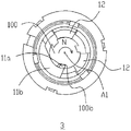
- FIG. 3 is a schematic exploded view of a driving assembly in a first embodiment of the present invention.
- FIG. 4 is a schematic top plan view of a driving assembly in a first embodiment of the present invention.
- Figure 5 is a schematic view showing the installation of the pushing portion of the coupling member in the first embodiment of the present invention
- Figure 6 is a first schematic view showing a state in which the drive assembly and the drive shaft in the image forming apparatus are engaged in the first embodiment of the present invention
- Figure 7 is a second schematic view showing the process of engaging the drive assembly in the first embodiment of the present invention with the drive shaft in the image forming apparatus;
- Figure 8 is a schematic view showing the drive assembly being disengaged from the drive shaft in the first embodiment of the present invention.
- Figure 9 is an exploded perspective view showing a driving assembly in a second embodiment of the present invention.
- Figure 10 is a schematic view of a positioning member in a drive assembly in a second embodiment of the present invention.
- Figure 11 is a schematic view of a coupling member in a drive assembly in a second embodiment of the present invention.
- FIG. 12 is a first schematic view showing a driving assembly and a drive shaft in a second embodiment of the present invention.
- Figure 13 is a schematic view showing a second state of the drive assembly and the drive shaft in the second embodiment of the present invention.
- Figure 14 is another schematic cross-sectional view showing the engagement of the drive shaft of the image forming apparatus with the drive assembly in the second embodiment of the present invention
- Figure 15 is a schematic view of a drive assembly in a third embodiment of the present invention.
- Figure 16 is a partially cutaway cross-sectional view showing the drive assembly of the third embodiment of the present invention.
- Figure 17 is a schematic view showing the mounting of a magnetic component of a drive assembly in a third embodiment of the present invention.
- Figure 18 is a first schematic view showing a driving assembly and a drive shaft in a third embodiment of the present invention.
- Figure 19 is a schematic view showing a second state of the drive assembly and the drive shaft in the third embodiment of the present invention.
- FIG. 20 is a schematic exploded view of a driving assembly according to a fourth embodiment of the present invention.
- Figure 21 is a partially cutaway structural view showing a drive assembly in a fourth embodiment of the present invention.
- Figure 22 is a schematic view showing the structure of the drive assembly before the drive shaft in the image forming apparatus is engaged in the fourth embodiment of the present invention
- Figure 23 is a schematic view showing the structure of the drive unit in engagement with the drive shaft in the image forming apparatus in the fourth embodiment of the present invention.
- Figure 24 is a cross-sectional view showing a driving force assembly in a fifth embodiment of the present invention.
- Figure 25 is a schematic view showing the first state of the drive assembly and the drive shaft in the fifth embodiment of the present invention.
- Figure 26 is a schematic view showing the second state of the drive assembly and the drive shaft in the fifth embodiment of the present invention.
- Figure 27 is a schematic view showing the third state of the drive assembly and the drive shaft in the fifth embodiment of the present invention.
- FIG. 1 is a schematic structural view of a process cartridge 1 according to an embodiment of the present invention.
- the process cartridge 1 includes a casing 2 in which a developer is stored, a photosensitive drum 4 rotatably supported on the casing 2, and a drive unit 3 mounted at a longitudinal end of the photosensitive drum 4 for receiving image formation
- the driving force transmitted by the device drives the photosensitive drum 4 to rotate.
- FIG. 2 it is a schematic structural view of the image forming apparatus driving shaft 100 in the prior art.
- the drive shaft 100 is substantially cylindrical, and three circumferentially distributed recesses 100b (only one shown) are provided on the circumferential surface of the drive shaft 100.
- One end of the drive shaft 100 is connected to the elastic member 101, and the drive shaft 100 can be extended in the A1 direction or in the A2 direction in the axial direction by the elastic force of the elastic member 101.
- the drive shaft 100 has a certain gap h with the image forming apparatus frame in the direction of the vertical axis.
- the drive shaft 100 When the drive shaft 100 is subjected to an external force perpendicular to the axial direction, the drive shaft 100 can be inclined with respect to the axial direction in the A3 or A4 direction.
- the drive assembly 3 cooperates with the drive shaft 100 to rotate the photosensitive drum, and the specific fitting process will be described in detail below.
- the drive assembly 3 of the present embodiment includes a coupling member 5 and a positioning member 6.
- the coupling member 5 is substantially cylindrical and engages with the drive shaft 100 in the image forming apparatus to receive and transmit a driving force to the photosensitive drum 4, and the coupling member 5 is substantially coaxial with the photosensitive drum 4.
- the coupling member 5 includes a main body portion 7, a power receiving portion 11a, a support portion 11b, and a pushing portion 12.
- the main body portion 7 is a hollow cylindrical shape having a first end 9 and a second end 10 in the direction of the axis X; the outer circumferential surface of the first end 9 can be inserted into the inner wall of the drum of the photosensitive drum 4, through the interference
- the coupling member 5 is fitted to the photosensitive drum 4, and generally, in order to prevent the coupling member 5 from coming off the photosensitive drum 4, an appropriate amount of adhesive may be applied on the outer circumferential surface of the first end 9, so that the coupling member 5 and the photosensitive member are sensitized.
- the inner wall of the cylinder of the drum 4 fits more compactly; the second end 10 is a part of the drum of the photosensitive drum 4 which is coupled to the coupling member 5.
- the support portion 11b is configured as a support plate that protrudes from the inner wall of the main body portion 7 in the radial direction toward the axis X
- the power receiving portion 11a is a hook portion that protrudes from the support portion 11b toward the axis X
- the power receiving portion 11a and the support portion 11b They are all made of a rigid material and are integrally formed with the main body portion 7 and are not movable relative to the main body portion 7.
- the pressing portion 12 is detachably mounted in the main body portion 7.
- the main body portion 7 is provided with a protruding portion 15 projecting from the inner wall thereof toward the axis X in the radial direction, and the protruding portion 15 is integrally formed with the main body portion 7 at An opening 16 is formed between the protruding portion 15 and the supporting portion 11b, and the pushing portion 12 can be installed into the opening 16.
- the pushing portion 12 is specifically configured as two, and is asymmetrically disposed on the main body with respect to the circumferential direction.
- the pressing portion 12 is formed with a mounting hole 12a, a first limiting portion 12b, and a second limiting portion 12c.
- the elastic member 14 is mounted in the mounting hole 12a when the pushing portion 12 is mounted in the opening 16.
- the elastic member 14 abuts against the inner wall of the main body portion 7 and the other end abuts in the mounting hole 12a. Therefore, the pressing portion 12 can move in the radial direction under the action of the elastic member 14;
- the amount of movement of the pushing portion 12 in the radial direction, the protruding portion 15 is provided with a first projecting portion 15a at one end forming the opening 16, and the support portion 11b is provided with a second projecting portion 11b1 at one end forming the opening 16, first A space is formed between the protruding portion 15a and the second protruding portion 11b1 in the radial direction, the first limit Portion 12b and the second stopper portion 12c can move only in the space to limit movement amount forcible pushing portion 12 in the radial direction.
- the positioning member 6 is configured in a substantially boss shape and is mountable to the first end 9 of the coupling member 5, and is connected to the first end 9 of the coupling member 5 by an adhesive or a snap or the like and stably mounted at the first end 9
- the inner wall of the cylinder is closed and the axial end of the first end 9 of the coupling member 5 is closed.
- the positioning member 6 is directly engaged with the axial end of the first end 9 by an interference fit such that the positioning member 6 is mounted on the coupling member 5.
- the positioning member 6 is formed with a positioning groove 8, and the positioning member 6 is explained below in conjunction with FIG. 2 to restrict and position the movement of the image forming apparatus drive shaft 100 in the axial direction.
- the front end 100a of the image forming apparatus drive shaft 100 has a conical shape, and the positioning groove 8 of the positioning member 6 receives and accommodates the front end 100a of the drive shaft 100. Since the positioning member 6 is fixed in the process cartridge, movement does not occur, so the drive is driven. During the transmission of the force, the drive shaft 100 has a tendency to move toward the side of the positioning member 6 under the action of the elastic member 101, but since the front end 100a of the drive shaft 100 abuts against the positioning groove 8, the positioning groove 8 is restricted. The movement of the drive shaft 100 in the axial direction.
- the drive unit 3 in this embodiment is provided with the positioning member 6 in order to make the transmission of the driving force more stable. Alternatively, the positioning member 6 may be omitted.
- the pushing portion 12 is further provided with a pressing surface 12d facing the axis of the main body portion 7 and a force receiving portion 12e.
- the guide urging portion 11a1 provided on the power receiving portion 11a abuts and urges the front end 100a of the drive shaft 100.
- the power receiving portion 11a applies a radial direction force to the drive shaft 100, forcing the axis of the drive shaft 100 to be inclined with respect to the axis of the main body portion 7, and the drive shaft 100 is in a plane equal to the power receiving portion 11a.
- the axial center position is shifted from A1 to A2, and at the same time, the front end 100a of the drive shaft 100 abuts against the force receiving portion 12e on the urging portion 12 so that the urging portion 12 overcomes the elastic force of the elastic member 14 toward the main body portion 7.
- the outer side is moved radially, that is, the pushing portion 12 is pressed by the drive shaft 100 to move radially away from the axis A1.
- the thrust portion 12 is abutted against the outer surface of the drive shaft 100 in order to prevent the pushing portion 12 from entering the recess 100b of the drive shaft 100.
- the minimum arc length of the forced push surface 12d is set longer than the arc length of the concave portion 100b of the drive shaft 100, and as the drive shaft 100 is further rotated in the N direction, the drive shaft 100 is rotated until its concave portion 100b is opposed to the power receiving portion 11a.
- the urging portion 12 presses the drive shaft 100 under the elastic potential energy accumulated by the elastic member 14 and moves in the radial direction near the axis A1, forcing the concave portion 100b of the drive shaft 100 to mesh with the power receiving portion 11a.
- the drive shaft 100 is further rotated in the N direction, as shown in FIG.
- the power receiving portion 11a abuts on a surface of the recess 100b, and the drive shaft 100 transmits the driving force through the recess 100b at the abutment of the power receiving portion 11a.
- the power receiving portion 11a drives the photosensitive drum to rotate in the N direction.
- the pressing portion 12 always abuts against the outer circumferential surface of the driving shaft 100 under the elastic force of the elastic member 14, and therefore, the driving shaft 100 does not cause the concave portion 100b and the power receiving portion due to its own centrifugal force when rotating.
- the minimum arc length of the thrust surface 12d is defined to be larger than the maximum arc length of the opening of the concave portion 100b, and therefore, during the rotation of the drive shaft 100
- the pushing portion 12 and the recess 100b are always spaced apart.
- the power receiving portion 11a of the drive unit 3 and the recess 100b of the drive shaft 100 interfere with each other near a portion of the front end 100a.
- the power receiving portion 11a abuts against the recess 100b of the drive shaft 100.
- the power receiving portion 11a applies a component force in the radial direction to the drive shaft 100, and the drive shaft 100 is inclined with respect to the axis of the main body portion 7 by the radial force applied by the power receiving portion 11a, and the drive shaft 100 is shifted from A1 to A3 in a plane in a plane equal to the power receiving portion 11a, and the urging portion 12 is urged to move radially away from the axis A1 by the drive shaft 100 as the drive shaft 100 is displaced.
- the power receiving portion 11a is disengaged from the recess 100b of the drive shaft 100 during the radial offset of the drive shaft 100, the drive shaft 100 no longer interferes with the drive assembly 3, and the process cartridge 1 can be smoothly taken out from the image forming apparatus.
- the drive assembly 20 of the present embodiment includes a positioning member 25 and a coupling member 24.
- the coupling member 24 is configured to be substantially cylindrical and engages with the drive shaft 100 in the image forming apparatus to receive and transmit a driving force to the photosensitive drum, thereby driving the photosensitive drum to rotate.
- the coupling member 24 includes a main body portion 26, a first power receiving portion 21b, a second power receiving portion 22b, a first reinforcing portion 21a, a second reinforcing portion 22a, and a positioning boss 23.
- the body portion 26 is configured as a hollow cylinder having a first end 27 and a second end 28 in the axial direction B; the axial end of the first end 27 is provided as a hole, and the outer circumferential surface of the first end 27 is provided with a plurality of Guide ribs 27a, the guide ribs 27a can guide the insertion of the coupling member 24 during the insertion of the coupling member 24 into the photosensitive drum, usually in order to make the coupling member 24 more closely connected to the photosensitive drum, and also at the first end 27 An appropriate amount of adhesive is applied to the outer circumferential surface such that the first end 27 of the coupling member 24 is bonded to the inner wall of the photosensitive drum to form a tight fit.
- the axial end of the second end 28 is provided as a hole.
- the first power receiving portion 21 b is configured in a columnar shape extending from the main body portion 26 in the radial direction toward the axis X, and the main body portion 26 is provided at substantially the center of the coupling member 24 in the axial direction B.
- the shape of the second power receiving portion 22b is substantially the same as the shape of the first power receiving portion 21b, and is configured to have a columnar shape extending from the main body portion 26 toward the axis X, and the second power receiving portion 22b and the first power receiving portion 21b are located at the coupling member.
- the first power receiving portion 21b and the second power receiving portion 22b are asymmetrically disposed on the main body portion 26 with respect to the axial direction B.
- the first power receiving portion 21b and the second power receiving portion 22b are both made of a rigid material, are not movable relative to the main body portion 26, and are integrally formed with the main body portion 26.
- the first reinforcing portion 21a extends from the main body portion 26 and intersects with the first power receiving portion 21b to increase the strength of the first power receiving portion 21b; the second reinforcing portion 22a also extends from the main body portion 26 and the second power receiving portion 22b When intersected, the strength of the second power receiving portion 22b can be increased.
- the positioning bosses 23 in this embodiment are provided in three, and are evenly distributed in the circumferential direction of the main body portion 26.
- the positioning member 25 is configured in a substantially boss shape and is mountable to the first end 27 of the coupling member 24, and can be coupled and stabilized to the first end 27 of the coupling member 24 by means of an adhesive or a snap. It is mounted within the circumferential inner wall of the first end 27 and encloses the axial end of the first end 27 of the coupling member 24.
- the positioning member 25 is provided with a positioning buckle 25b, and the positioning buckle 25b is provided with three, which can be engaged with the positioning boss 23 in the coupling member 24, so that the positioning member 25 is connected to the coupling member 24.
- a positioning groove 25a is also provided in the positioning member 25, and the positioning groove 25a is formed as a tapered inner concave portion at a center position of the positioning member 25 and is symmetrical with respect to the axis X of the coupling member 24.
- the drive unit 20 in this embodiment is provided with the positioning member 25 in order to make the transmission of the driving force more stable.
- the positioning member 25 may be omitted.
- the first power receiving portion 21b of the coupling member 24 abuts the second power receiving portion 22b against the circumferential surface of the drive shaft 100 and applies it to the drive shaft 100. a force perpendicular to the axial direction such that the axial position of the drive shaft 100 is deflected from A1 to A2, so that the coupling member 24 and the drive shaft 100 are in a state as shown in FIG.
- the second power receiving portion 22b and the first power are The receiving portion 21b is engaged with the concave portion 100b of the drive shaft, respectively, so that the drive shaft 100 drives the coupling member 24 to rotate together in the N direction, and the photosensitive drum is coupled with the coupling member 24 to drive the photosensitive drum to rotate together.
- the drive shaft 100 and the positioning member 25 are in a state as shown in FIG. 14, the front end 100a of the drive shaft 100 is configured in a conical shape, and the positioning groove 25a of the positioning member 25 receives and accommodates the front end of the drive shaft 100.
- the drive shaft 100 since the positioning member 25 is fixed in the process cartridge and does not move, the drive shaft 100 tends to move toward the side of the positioning member 25 even under the action of the elastic member during the driving force transmission, but is driven by the drive member.
- the front end 100a of the shaft 100 abuts against the positioning groove 25a.
- the positioning groove 25a restricts the movement of the driving shaft 100 in the axial direction, and the driving shaft 100 stably drives the driving assembly 20 to rotate.
- the drive assembly 30 of the present embodiment includes a main body portion 31, a coupling member 32, and a positioning member 33, and the drive assembly 30 is rotatable about the axis X.
- the coupling member 32 includes a power receiving portion 34 and a support portion 35 that is movably mounted in the support portion 35.
- the support portion 35 includes a groove portion 35a which is an open groove formed in the circumferential outer wall of the main body portion 31, and an opening thereof which faces the outside of the main body portion 31 in the radial direction; the protruding portion 35b is formed in the main body portion 31.
- the circumferential inner wall and the radial direction toward the axis A1 are convex, the protruding portion 35b is integrally formed with the groove portion 35a, and the protruding portion 35b is formed with a first opening 35C that communicates with the groove portion 35a.
- the power receiving portion 34 includes a projecting portion 34a and a restricting portion 34b. When the power receiving portion 34 is mounted in the support portion 35, the projecting portion 34a sequentially moves through the groove portion 35a and the first opening 35c toward the axis A1 in the radial direction.
- the coupling members 32 are specifically provided in three, and the power receiving portions 34 of the coupling members 32 are each made of a magnetic metal material.
- a magnetic member 36 is sleeved around the protruding portion 34a of the power receiving portion 34.
- the magnetic member 36 is formed with a second opening 36a, and the protruding portion 34a of the power receiving portion 34 passes through the second opening 36a to make the magnetic member. 36 abuts on the restriction portion 34b of the power receiving portion 34.
- the magnetic member 36 When the power receiving portion 34 is mounted in the support portion 35, the magnetic member 36 is attached to the groove portion 35a of the support portion 35 with the power receiving portion 34, and the magnetic member 36 is sandwiched between the restricting portion 34b and the support portion 35 of the power receiving portion 34. Between the protrusions 35b. Since the magnetic member 36 has a magnetic force, the power receiving portion 34 made of a magnetic metal material can be moved in the radial direction in the first opening 35c under the attraction of the magnetic member 36. Alternatively, the magnetic portion 36 may be disposed on the protruding portion 34a of the power receiving portion 34 or directly set the power receiving portion 34 to be magnetic, and the power receiving portion 34 is attracted to each other such that the power receiving portion 34 is at the first position.
- the opening 35c moves in the radial direction.
- the magnetic member 36 may be separately disposed in the power receiving portion 34 and the support portion 35, wherein the magnetic member 36 on the power receiving portion 34 and the magnetic member 36 in the support portion 35 are opposite to each other, and pass through the magnetic member 36.
- the mutual repulsiveness may also cause the power receiving portion 34 to move in the radial direction in the first opening 35c.
- the front end 100a of the drive shaft 100 abuts against the projecting portion 34a of the power receiving portion 34, and at this time, as shown in Fig. 18, the drive shaft 100 is oriented
- the power receiving portion 34 applies a force in the radial direction to force the power receiving portion 34 to move radially away from the axis A1 in the support portion 35 until the front end 100a of the drive shaft 100 is housed in the positioning member 33.
- the power receiving portion 34 since the power receiving portion 34 is attracted by the magnetic member 36, the power receiving portion 34 moves in the radial direction toward the axis A1, Thereby, the recess 100b of the drive shaft 100 is engaged, the drive shaft 100 transmits the driving force to the power receiving portion 34 through the recess 100b against the power receiving portion 34, and the power receiving portion 34 further transmits the driving force to the driving assembly 30.
- the photosensitive drum is also rotated.
- the power receiving portion 34 when the process cartridge is detached, the power receiving portion 34 is always attracted to each other due to the action of the magnetic member 36, so that the power receiving portion 34 is not pressed by the drive shaft 100 to be detached from the support portion 35; Further, the power receiving portion 34 is caught by the first opening 35c of the support portion 35, and when the power receiving portion 34 is rotated by the drive shaft 100, the centrifugal force applied to the power receiving portion 34 by the drive shaft 100 does not force the power receiving portion 34 from The support portion 35 is detached.
- the drive assembly 40 of the present embodiment includes a main body portion 41 and a coupling kit 42.
- the coupling kit 42 is mounted into the main body portion 41 and can drive the main body portion 41 to rotate.
- the coupling set 42 includes a coupling member 43 that supports the bottom plate 44, the axle pin 46, and the resilient member 45.
- the coupling member 43 is provided substantially in an L shape, and has a pressing portion 43b and a power receiving portion 43c, and one rotation center 43a is provided between the pressing portion 43b and the power receiving portion 43c.
- the support base plate 44 is equidistantly arranged in the circumferential direction with three coupling member mounting portions 44a, which are specifically provided with a pair of oppositely disposed mounting ribs, and an installation space is formed between the pair of the mounting ribs, and the pressing portion 43b of the coupling member 43 is mounted.
- a shaft pin 46 is rotatably mounted at the coupling member mounting portion 44a through the above-described mounting rib, the rotation center 43a of the coupling member 43, and the elastic member 45.
- the elastic member 45 is specifically configured as a torsion spring, one of which has a free end abutting the support base 44, and the other free end abuts against the side wall of the coupling member 43. To reduce the space, the other free end is on the support base 44.
- the inner arm surface of the coupling member 43 is abutted in the circumferential direction, and of course, it is also possible to selectively abut or connect with any other place of the coupling member 43.
- a restriction portion (not shown) that restricts the stroke of the coupling member 43 to rotate outward is further disposed on the support base 44, and the restriction portion may be coupled to the coupling member 43 after the coupling member 43 is rotated outward by a certain stroke. Contacting restricts the coupling member 43 to further rotate outward.
- the coupling member 42 since the coupling member 42 is mounted in the main body portion 41, the coupling member 43 will be located in the hollow cylinder of the main body portion 41, and therefore, the inner side wall surface of the main body portion 41 can be utilized to restrict the coupling member 43 from rotating outward. It is not necessary to provide a restriction on the support base 44.
- only a schematic view of the elastic member and the pin of the coupling member 43 is shown in the drawing, it being understood that all of the coupling members 43 are mounted with the elastic member and the pin.
- the inner surface of the main body portion 41 is further provided with a guide portion 41a which can guide the movement of the power receiving portion 43c of the coupling member 43, and the driving force received by the power receiving portion 43c from the image forming device can also be It is transmitted to the main body portion 41 through the guide portion 41a and drives the main body portion 41 to rotate.
- the coupling member 43 can also transmit the driving force to the main body portion 41 through the support base 44.
- the mounting portion of the coupling member 43 may be disposed in the support base 44.
- a mounting portion may be directly disposed on the inner wall of the main body portion 41, and the coupling member 43 may be directly mounted to the main body portion 41. On the inside wall.
- the process cartridge is mounted in the image forming apparatus in an X direction substantially parallel to the axis of the drive shaft 100, and the coupling member 43 is elastic member 45 before the coupling member 43 comes into contact with the drive shaft 100.
- the biasing force biasing position is a position that is rotated outward to open, and for convenience of description, a position at which the coupling member 43 is rotated outward to be opened later is referred to as an opening position of the coupling member 43.
- the coupling member 43 When the coupling member 43 is in the open position, the front end 100a of the drive shaft 100 will pass over the power receiving portion 43c of the coupling member 43, and abut against the pressing portion 43b of the coupling member 43 to apply pressure, and the pressing portion 43b receives the pressing of the driving shaft 100. After the pressure, the elastic force of the elastic member 45 is rotated inwardly against the elastic force.
- the power receiving portion 43c is engaged in the recess 100b of the drive shaft 100 to complete the engagement with the drive shaft 100.
- the position where the coupling member 43 is rotated inward and finally stopped at the recess 100b of the drive shaft 100 is referred to as a closed position of the coupling member 43.
- the drive shaft 100 transmits a rotational driving force to the drive unit 40 by the engagement of the recess 100b with the power receiving portion 43c, and the drive unit 40 transmits the rotational driving force to the respective force receiving members in the process cartridge.
- the power receiving portion 43c has an inner guide portion 43c2 that abuts against the closed end of the concave portion 100b of the drive shaft 100 on the side close to the front end 100a when the process cartridge needs to be detached, forcing the coupling member 43 to move from the closed position to the open position. The position is ultimately disengaged from the drive shaft 100.
- the outer guide portion 43c1 is provided at a position opposite to the inner guide portion 43c2 on the power receiving portion 43c of the coupling member 43 in the present embodiment, and the outer guide portion 43c1 is disposed such that even the coupling member 43 is provided.
- the coupling member 43 can be further rotated outward by the engagement of the outer guide portion 43c1 with the front end 100a of the drive shaft 100, and the front end 100a of the drive shaft 100 can smoothly pass over the power receiving portion 43c.
- the drive unit 50 of the present embodiment includes a main body portion 51, a pressing portion 52, and a power receiving portion 53.
- the pressing portion 52 is movably provided in the main body portion 51. Specifically, the pressing portion 52 moves axially along the circumferential inner wall of the main body portion 51 along the axis X.
- the power receiving portion 53 is specifically provided in three. In the present embodiment, the power receiving portion 53 is specifically configured as a triangular block including a tip end 53a and a flat portion 53b.
- the circumferential inner walls of the main body portion 51 are respectively formed with three mounting grooves 51a, and the power receiving portions 53 are respectively mounted in the mounting grooves 51a by the connecting pins 54, and are rotatable around the connecting pins 54.
- the drive shaft 100 in the image forming apparatus is combined with the drive assembly 50.
- the projection 100c of the drive shaft 100 abuts against the pressing portion 52, and the pressing portion 52 is pressed to move closer to the power receiving portion 53 along the axis X.
- the front end 100a of the drive shaft 100 abuts against the tip end 53a of the power receiving portion 53, forcing the power receiving portion 53 to rotate about the connecting pin 54 to avoid a position interfering with the front end 100a, that is, the power receiving portion 53 is rotated to its flat portion 53b and The drive shaft 100 is opposed to each other.
- the front end 100a of the drive shaft 100 does not contact the power receiving portion 53.
- the drive shaft 100 presses the pressing portion 52 to abut the pressing portion 52 against the power receiving portion 53, forcing the power receiving portion 53 to rotate about the connecting pin 54.
- the power receiving portion 53 is pressed by the pressing portion 52 to rotate to its tip end 53a to engage with the concave portion 100b of the drive shaft 100, when the drive shaft 100 is image-formed by the image forming apparatus
- the drive unit 50 receives the driving force from the drive shaft 100 and rotates by the power receiving unit 53.
- the power receiving portion 53 is always pressed by the pressing portion 52.
- the drive shaft 100 When the drive shaft 100 is driven to rotate by the motor of the image forming apparatus, as the concave portion 100b of the drive shaft 100 is rotated to face the power receiving portion 53, the power receiving portion 53 pressed by the pressing portion 52 is rotated to the tip end 53a thereof. The recess 100b of the drive shaft 100 is engaged, and the drive unit 50 is rotated by receiving a driving force from the drive shaft 100 through the power receiving portion 53.
- the power receiving portion in the coupling member is formed in a movable form with respect to the main body portion, and specifically, in the embodiment 3, the power receiving portion is disposed at the main body portion with respect to the main body portion. Moving in the radial direction, but the moving direction of the power receiving portion with respect to the main body portion is not limited to the radial direction, for example, the power receiving portion may be moved in a direction at a certain angle with the radial direction of the main body portion, in the embodiment.
- the power receiving portion is disposed to be rotatable in a radial direction of the main body with respect to the main body portion about one fulcrum, but the rotation direction of the power receiving portion is not limited to the radial direction of the main body portion, for example, power receiving The portion may be rotated in a direction that is at an angle to the radial direction of the main body portion.
- the above solution differs from the prior art in that the power receiving portion is integrally moved relative to the main body portion, between the power receiving portion and the main body portion.
- the power receiving portion can be integrally formed with the main body portion, and the support portion for supporting the power receiving portion between the power receiving portion and the main body portion is directly in the form of a fixed support, which can greatly simplify the production and processing cost of the coupling member, and at the same time
- the coupling member is not damaged by the large torque.
- the driving assembly provided by the invention does not have a local thin material structure, and the molding processing process of the driving assembly is simple, and the complicated processing technology of the metal parts in the plastic parts does not occur, and the driving is greatly reduced.
- the processing of the components is difficult to form and the stability of the power transmission of the drive components is improved.
- the technical problem that the molding process of the driving component is complicated, the production cost is high, and the driving force transmission is unstable is solved in the prior art.
Landscapes
- Physics & Mathematics (AREA)
- General Physics & Mathematics (AREA)
- Engineering & Computer Science (AREA)
- Computer Vision & Pattern Recognition (AREA)
- Electrophotography Configuration And Component (AREA)
Abstract
L'invention concerne une cartouche de traitement (1). La cartouche de traitement (1) comprend un ensemble d'entraînement (3) pouvant venir en prise avec un arbre d'entraînement (100) ayant une cavité dans un appareil de formation d'image. L'ensemble d'entraînement (3) comprend : un élément de couplage (5) configuré pour recevoir une force d'entraînement de l'arbre d'entraînement (100) et pourvu d'une partie de réception d'énergie (11a) pouvant venir en prise avec la cavité de l'arbre d'entraînement (100) ; et une partie de corps (7) pouvant tourner après avoir reçu la force d'entraînement transmise par la partie de réception d'énergie (11a). Lorsque l'ensemble d'entraînement (3) est monté dans l'appareil de formation d'image, la partie de réception d'énergie (11a) peut forcer l'axe de l'arbre d'entraînement (100) de façon à l'incliner par rapport à l'axe de l'ensemble d'entraînement (3). L'élément de couplage (5) force l'arbre d'entraînement (100) de façon à l'incliner pour mettre en oeuvre la mise en prise et le désengagement, résolvant ainsi le problème technique présent dans l'état de la technique selon lequel l'ensemble d'entraînement (3) a un processus de moulage compliqué, un coût de production élevé et une transmission instable de la force d'entraînement.
Priority Applications (1)
| Application Number | Priority Date | Filing Date | Title |
|---|---|---|---|
| US16/886,006 US11016439B2 (en) | 2017-11-30 | 2020-05-28 | Process cartridge |
Applications Claiming Priority (8)
| Application Number | Priority Date | Filing Date | Title |
|---|---|---|---|
| CN201721638906.1 | 2017-11-30 | ||
| CN201721638906.1U CN207601523U (zh) | 2017-11-30 | 2017-11-30 | 一种驱动组件及包含该驱动组件的处理盒 |
| CN201721638864.1 | 2017-11-30 | ||
| CN201721638864.1U CN207601522U (zh) | 2017-11-30 | 2017-11-30 | 一种驱动力传递机构及处理盒 |
| CN201821559464.6 | 2018-09-25 | ||
| CN201821559464 | 2018-09-25 | ||
| CN201821582479.4 | 2018-09-27 | ||
| CN201821582479 | 2018-09-27 |
Related Child Applications (1)
| Application Number | Title | Priority Date | Filing Date |
|---|---|---|---|
| US16/886,006 Continuation US11016439B2 (en) | 2017-11-30 | 2020-05-28 | Process cartridge |
Publications (1)
| Publication Number | Publication Date |
|---|---|
| WO2019105353A1 true WO2019105353A1 (fr) | 2019-06-06 |
Family
ID=66664698
Family Applications (1)
| Application Number | Title | Priority Date | Filing Date |
|---|---|---|---|
| PCT/CN2018/117774 Ceased WO2019105353A1 (fr) | 2017-11-30 | 2018-11-28 | Cartouche de traitement |
Country Status (2)
| Country | Link |
|---|---|
| US (1) | US11016439B2 (fr) |
| WO (1) | WO2019105353A1 (fr) |
Families Citing this family (1)
| Publication number | Priority date | Publication date | Assignee | Title |
|---|---|---|---|---|
| CA3191750A1 (fr) * | 2020-09-17 | 2022-03-24 | Canon Kabushiki Kaisha | Cartouche, unite de tambour et appareil de formation d'image |
Citations (11)
| Publication number | Priority date | Publication date | Assignee | Title |
|---|---|---|---|---|
| US5983055A (en) * | 1996-03-19 | 1999-11-09 | Sharp Kabushiki Kaisha | Photosensitive element for electrophotography |
| CN1728006A (zh) * | 2004-06-28 | 2006-02-01 | 三星电子株式会社 | 减少由图像承载体引起的成像误差的成像装置及制造方法 |
| CN202904225U (zh) * | 2012-09-05 | 2013-04-24 | 江西镭博钛电子科技有限公司 | 动力接收头及处理盒 |
| CN203502738U (zh) * | 2012-09-21 | 2014-03-26 | 兄弟工业株式会社 | 从动构件、盒以及图像形成设备 |
| CN104765257A (zh) * | 2014-01-06 | 2015-07-08 | 兄弟工业株式会社 | 具有驱动力接收构件的显影盒 |
| CN205229681U (zh) * | 2015-10-26 | 2016-05-11 | 中山鑫威打印耗材有限公司 | 一种动力耦合装置以及处理盒 |
| WO2016088303A1 (fr) * | 2014-12-03 | 2016-06-09 | Canon Kabushiki Kaisha | Appareil de formation d'image |
| WO2016137014A1 (fr) * | 2015-02-27 | 2016-09-01 | キヤノン株式会社 | Unité tambour, cartouche et élément d'accouplement |
| CN205827076U (zh) * | 2016-05-31 | 2016-12-21 | 江西亿铂电子科技有限公司 | 一种可拆卸的安装到成像装置中的盒 |
| CN207601522U (zh) * | 2017-11-30 | 2018-07-10 | 江西亿铂电子科技有限公司 | 一种驱动力传递机构及处理盒 |
| CN207601523U (zh) * | 2017-11-30 | 2018-07-10 | 江西亿铂电子科技有限公司 | 一种驱动组件及包含该驱动组件的处理盒 |
Family Cites Families (4)
| Publication number | Priority date | Publication date | Assignee | Title |
|---|---|---|---|---|
| US9684274B2 (en) * | 2013-08-13 | 2017-06-20 | General Plastic Industrial Co., Ltd. | Transmission device for photosensitive drum and drum device having same |
| CN203503738U (zh) | 2013-10-16 | 2014-03-26 | 无锡华燕新电源有限公司 | 一种胶体动力电池铸焊用正负极板板栅结构 |
| ES2870050T3 (es) * | 2016-08-26 | 2021-10-26 | Canon Kk | Unidad de tambor, aparato de formación de imágenes electrofotográficas y elemento de acoplamiento |
| BR112019003028A2 (pt) * | 2016-08-26 | 2019-05-14 | Canon Kabushiki Kaisha | unidade de tambor, cartucho, aparelho de formação de imagem eletrofotográfica e elemento de acoplamento |
-
2018
- 2018-11-28 WO PCT/CN2018/117774 patent/WO2019105353A1/fr not_active Ceased
-
2020
- 2020-05-28 US US16/886,006 patent/US11016439B2/en not_active Expired - Fee Related
Patent Citations (12)
| Publication number | Priority date | Publication date | Assignee | Title |
|---|---|---|---|---|
| US5983055A (en) * | 1996-03-19 | 1999-11-09 | Sharp Kabushiki Kaisha | Photosensitive element for electrophotography |
| CN1728006A (zh) * | 2004-06-28 | 2006-02-01 | 三星电子株式会社 | 减少由图像承载体引起的成像误差的成像装置及制造方法 |
| CN202904225U (zh) * | 2012-09-05 | 2013-04-24 | 江西镭博钛电子科技有限公司 | 动力接收头及处理盒 |
| CN203502738U (zh) * | 2012-09-21 | 2014-03-26 | 兄弟工业株式会社 | 从动构件、盒以及图像形成设备 |
| CN104765257A (zh) * | 2014-01-06 | 2015-07-08 | 兄弟工业株式会社 | 具有驱动力接收构件的显影盒 |
| WO2016088303A1 (fr) * | 2014-12-03 | 2016-06-09 | Canon Kabushiki Kaisha | Appareil de formation d'image |
| WO2016137014A1 (fr) * | 2015-02-27 | 2016-09-01 | キヤノン株式会社 | Unité tambour, cartouche et élément d'accouplement |
| CN205229681U (zh) * | 2015-10-26 | 2016-05-11 | 中山鑫威打印耗材有限公司 | 一种动力耦合装置以及处理盒 |
| CN106610576A (zh) * | 2015-10-26 | 2017-05-03 | 中山诚威科技有限公司 | 一种从动单元以及处理盒 |
| CN205827076U (zh) * | 2016-05-31 | 2016-12-21 | 江西亿铂电子科技有限公司 | 一种可拆卸的安装到成像装置中的盒 |
| CN207601522U (zh) * | 2017-11-30 | 2018-07-10 | 江西亿铂电子科技有限公司 | 一种驱动力传递机构及处理盒 |
| CN207601523U (zh) * | 2017-11-30 | 2018-07-10 | 江西亿铂电子科技有限公司 | 一种驱动组件及包含该驱动组件的处理盒 |
Also Published As
| Publication number | Publication date |
|---|---|
| US20200301356A1 (en) | 2020-09-24 |
| US11016439B2 (en) | 2021-05-25 |
Similar Documents
| Publication | Publication Date | Title |
|---|---|---|
| US12066786B2 (en) | Cartridge and drum unit for electrophotographic image forming apparatus | |
| US11353822B2 (en) | Cartridge and electrophotographic image forming apparatus | |
| AU2016414528B2 (en) | Driving assembly and developing cartridge | |
| CN107918263B (zh) | 带有驱动组件的处理盒 | |
| EP3444681B1 (fr) | Cartouche de traitement | |
| JP2010262056A (ja) | カートリッジ、及び電子写真画像形成装置 | |
| CN107918259B (zh) | 一种控制机构以及显影盒 | |
| CN110941168B (zh) | 一种驱动力传递机构及处理盒 | |
| AU2017271569A1 (en) | Driving force reception assembly and processing box using assembly | |
| NL2019394B1 (en) | Process cartridge and photosensitive drum driving component cross-reference to related applications | |
| CN208000455U (zh) | 一种驱动组件以及包含该驱动组件的处理盒 | |
| CN105824213B (zh) | 驱动组件及显影盒 | |
| WO2019105353A1 (fr) | Cartouche de traitement | |
| JP2016040610A (ja) | カートリッジ、及び電子写真画像形成装置 | |
| WO2020029870A1 (fr) | Cartouche de traitement | |
| CN206557534U (zh) | 驱动组件与显影盒 | |
| US20180259898A1 (en) | End member, photoreceptor drum unit, and process cartridge | |
| CN205862103U (zh) | 显影盒及驱动组件 | |
| CN204406035U (zh) | 旋转力传递组件、感光鼓及处理盒 | |
| CN205899248U (zh) | 驱动组件与显影盒 | |
| CN223167032U (zh) | 一种处理盒 | |
| JP2017161930A (ja) | カートリッジ、及び電子写真画像形成装置 | |
| CN117666305A (zh) | 一种鼓单元及处理盒 |
Legal Events
| Date | Code | Title | Description |
|---|---|---|---|
| 121 | Ep: the epo has been informed by wipo that ep was designated in this application |
Ref document number: 18884821 Country of ref document: EP Kind code of ref document: A1 |
|
| NENP | Non-entry into the national phase |
Ref country code: DE |
|
| 122 | Ep: pct application non-entry in european phase |
Ref document number: 18884821 Country of ref document: EP Kind code of ref document: A1 |