WO2019106830A1 - 分散制御装置 - Google Patents
分散制御装置 Download PDFInfo
- Publication number
- WO2019106830A1 WO2019106830A1 PCT/JP2017/043279 JP2017043279W WO2019106830A1 WO 2019106830 A1 WO2019106830 A1 WO 2019106830A1 JP 2017043279 W JP2017043279 W JP 2017043279W WO 2019106830 A1 WO2019106830 A1 WO 2019106830A1
- Authority
- WO
- WIPO (PCT)
- Prior art keywords
- memory
- control unit
- data
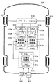
- shared
- cpu
- Prior art date
- Legal status (The legal status is an assumption and is not a legal conclusion. Google has not performed a legal analysis and makes no representation as to the accuracy of the status listed.)
- Ceased
Links
Images





Classifications
-
- G—PHYSICS
- G06—COMPUTING OR CALCULATING; COUNTING
- G06F—ELECTRIC DIGITAL DATA PROCESSING
- G06F11/00—Error detection; Error correction; Monitoring
- G06F11/07—Responding to the occurrence of a fault, e.g. fault tolerance
- G06F11/16—Error detection or correction of the data by redundancy in hardware
- G06F11/20—Error detection or correction of the data by redundancy in hardware using active fault-masking, e.g. by switching out faulty elements or by switching in spare elements
-
- G—PHYSICS
- G06—COMPUTING OR CALCULATING; COUNTING
- G06F—ELECTRIC DIGITAL DATA PROCESSING
- G06F15/00—Digital computers in general; Data processing equipment in general
- G06F15/16—Combinations of two or more digital computers each having at least an arithmetic unit, a program unit and a register, e.g. for a simultaneous processing of several programs
- G06F15/163—Interprocessor communication
- G06F15/173—Interprocessor communication using an interconnection network, e.g. matrix, shuffle, pyramid, star, snowflake
Definitions
- the present invention relates to a distributed control device.
- CPUs Central Processing Units
- RAMs Random Access Memories, main memories, memories
- IoT Internet of Things
- each layer performs distributed processing in each layer such as devices that constitute the entire industrial system, PLC (Programmable Logic Controller), cloud, etc. to communicate information mutually, and real world and virtual world Need to be connected organically.
- PLC Programmable Logic Controller
- Patent Document 1 describes a microprocessor application device having a distributed processing function in which distributed processing is performed by a plurality of microprocessors.
- the microprocessor application device described in Patent Document 1 aims to continue operation as a whole by degenerate operation as a whole even if some of the plurality of microprocessors fail. Then, for each device configuration determined by a combination of presence / absence of a failure of each microprocessor, program memory in which a program to be executed by each normal microprocessor is stored, and an abnormality of each microprocessor are detected , And program assignment means.
- the program allocation means determines one of the plurality of microprocessors as a master processor based on the abnormality detection result of the initialization means to determine the change of the device configuration, and the program memory specific to the new device configuration Are assigned to corresponding normal microprocessors.
- Patent Document 1 In the technology described in Patent Document 1, there is only one set of shared memory and initialization control unit shared by a plurality of microprocessors, and if these parts fail, there is a possibility of becoming a single failure point. And the configuration and operation for measures in case of failure of these parts are not specified.
- the master CPU needs to transfer the software at the time of degeneration to the slave CPU via the shared memory, which requires time, and it takes time to switch from the normal operation to the degeneration operation.
- An object of the present invention is to realize a distributed control device capable of avoiding the occurrence of a single failure point, reducing the transition delay time to the degeneration operation, and improving the safety and reliability.
- the present invention is configured as follows.
- a distributed control device In a distributed control device, a first operation control unit, a first reconfiguration control unit connected to the first operation control unit, and a first memory connected to the first reconfiguration control unit A second operation control unit, a second reconfiguration control unit connected to the second operation control unit, a second memory connected to the second reconfiguration control unit, and And a first shared data diagnosis unit connected to the second memory, a third operation control unit, and a third reconfiguration control unit connected to the third operation control unit. And a third memory connected to the third reconfiguration control unit, and a second shared data diagnosis unit connected to the third reconfiguration control unit and the third memory,
- the second memory includes the second dedicated memory space, a shared memory space with the first memory, and the third memory.
- the third memory has a dedicated memory space of the third memory, a shared memory space with the first memory, and a shared memory space with the second memory,
- the shared data diagnostic unit 1 diagnoses data stored in the shared space with the first memory in the second memory, rewrites erroneous data to correct data, and the second shared data diagnostic unit The data stored in the shared memory space with the first memory in the third memory is diagnosed, and the erroneous data is rewritten to the correct data.
- a distributed control that can avoid the occurrence of a single failure point, reduce the transition delay time to the degenerate operation, and improve the safety and reliability.
- the device can be realized.
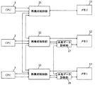
- FIG. 1 is a schematic configuration diagram of a distributed control device according to a first embodiment.
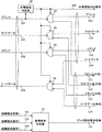
- FIG. 7 is a diagram illustrating an example of a configuration of a reconfiguration control unit according to the first embodiment.
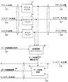
- FIG. 6 is a diagram showing an example of the configuration of a shared data diagnosis unit of the first embodiment.
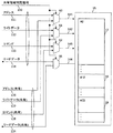
- FIG. 2 is a diagram showing an example of a memory configuration of the distributed control device of the first embodiment.
- FIG. 7 is an operation flowchart in the case where a failure occurs in a part of the distributed control device of the first embodiment and a transition is made to a degeneration operation. It is an operation
- FIG. 7 is a schematic configuration diagram of a distributed control device according to a second embodiment.
- FIG. 13 is a schematic explanatory view of a distributed control device according to a third embodiment. It is a figure which shows an example of the data frame output with respect to a control object apparatus from the reconfiguration
- FIG. 15 is a diagram showing an example of applying the distributed control device according to the fourth embodiment to a vehicle system.
- FIG. 18 is a diagram illustrating an example of applying the distributed control device according to the fifth embodiment to an industrial control system.
- Example 1 Embodiment 1 of the present invention will be described with reference to FIGS. 1 to 7A and 7B.
- FIG. 1 is a schematic block diagram of a distributed control apparatus according to a first embodiment of the present invention.
- FIG. 1 includes a CPU 1 (first operation control unit) and a memory 11 (first memory), a CPU 2 (second operation control unit) and a memory 12 (second memory), and a CPU 3 (a second operation control unit). It is an example of a distributed control device that performs distributed processing by a combination of a third operation control unit) and a memory 13 (third memory).
- the CPU 2 and the CPU 3 use the calculation result of the CPU 1 to perform processing, and the reconfiguration control unit 21 (first reconfiguration control unit) therefor, reconfiguration control Unit 22 (second reconfiguration control unit) and reconfiguration control unit 23 A (third reconfiguration control unit) is connected between each of the CPUs 1, 2 and 3 and each of the memories 11, 12 and 13, and the respective reconfiguration control units 21, 22 and 23 are also mutually connected. Communicate with each other.
- a shared data diagnosis unit 27 (first shared data diagnosis unit) is connected between the reconfiguration control unit 22 connected to the CPU 2 and the memory 12.
- a shared data diagnosis unit 28 (second shared data diagnosis unit) is connected between the reconfiguration control unit 23 connected to the CPU 3 and the memory 13.
- the shared data diagnosis unit 27 and the shared data diagnosis unit 28 are configured to mutually communicate data.
- FIG. 2 is a diagram showing an example of a detailed configuration of the reconfiguration control unit 22 shown in FIG.
- the address 101, the write data 102, the command 103, and the failure detection signal 132 are input to the reconfiguration control unit 22 from the CPU 2. Further, the failure detection signal 131 (failure detection signal No. 1) is input to the reconfiguration control part 22 from another reconfiguration control part 21 and the failure detection signal 133 (failure detection signal No. 3) from the reconfiguration control part 23 Is input.
- the shared space determination unit 30 determines the memory space used by the CPU 2 and the memory space shared by the CPU 1 and the CPU 3 in the memory 12. In this example, which memory space is shared by software operated by the control system Is predetermined.
- the demultiplexer 40 switches the output destination of the address 101 to the address 111 and the address (shared) 121 according to the result of the shared space determination signal 150 output from the shared space determination unit 30. If the address 101 is the memory space of the CPU 2, the demultiplexer 40 outputs the address 101 as the address 111 to the memory 12. If the address 101 is the memory space shared with the CPU 1 or CPU 3, the demultiplexer 40 outputs the address 101 ( It is output to the shared data diagnosis unit 27 as the sharing 121.
- the demultiplexer 41 outputs the write data 102 as the write data 112 to the memory 12, and the demultiplexer 42 outputs the command 103 as the command 113 to the memory 12.
- the demultiplexer 41 If the address 101 is a memory space shared by the CPU 1 or CPU 3, the demultiplexer 41 outputs the write data 102 as the write data (shared) 122 to the shared data diagnosis unit 27, and the demultiplexer 42 performs a command ( It is output to the shared data diagnosis unit 27 as the sharing) 123.
- the shared area determination signal 150 is output to the memory 12 as described later.
- the read data 114 is input from the memory 12 to the reconfiguration control unit 22, and the read data (shared) 124 is input from the shared data diagnosis unit 27.
- the selector 46 selects the read data 114 as the read data 104 and outputs it to the CPU 2.
- the selector 46 selects the read data (shared) 124 as the read data 104 and outputs it to the CPU 2.
- the failure location determination unit 31 is input from the failure detection signal 131 of the CPU 1 input from the reconfiguration control unit 21 of the CPU 1, the failure detection signal 132 of the CPU 2 input from the CPU 2, and the reconfiguration control unit 23 of the CPU 3 From the information with the failure detection signal 133 of the CPU 3, it is detected which one of the CPU 1, the CPU 2 and the CPU 3 has a failure.
- the failure point determination unit 31 outputs the data diagnosis request signal 137 to the shared data diagnosis unit 27 according to the failed CPU.
- the reconfiguration control unit 23 shown in FIG. 1 also has the same configuration as the reconfiguration control unit 22 shown in FIG. Further, the reconfiguration control unit 21 which is not connected to the shared data diagnosis unit 27 shown in FIG. 1 receives an address (shared) 121, a write data (shared) 122, a command (shared) from the reconfiguration control unit 22 in FIG.
- the configuration similar to that of the reconfiguration control unit 22 can be obtained by excluding the read data (shared) 124, the failure location determination unit 31, and the like.
- FIG. 3 is a diagram showing an example of a configuration of shared data diagnosis unit 27 shown in FIG.
- the shared data diagnosis unit 27 receives an address (shared) 121, a write data (shared) 122, a command (shared) 123, and a data diagnosis request signal 137 from the reconfiguration control unit 22. Further, read data (shared) 125 is input to the shared data diagnosis unit 27 from another shared data diagnosis unit 28.
- the address buffer 51 is configured to be able to hold a plurality of addresses (shared) 121, and sequentially outputs the contents of the held address (shared) 121 to the memory 12 as an address (shared) 126.
- the write data buffer 52 holds a plurality of write data (shared) 122 and sequentially outputs the write data (shared) 127 to the memory 12.
- the command buffer 53 holds a plurality of commands (shared) 123 and sequentially outputs the commands (shared) 128 to the memory 12.
- the fault diagnosis state machine 56 uses the command (shared) 128 in the memory space indicated by the address (shared) 126 at the timing when the occurrence of a fault is detected by any of the CPUs 1 to 3 according to the value of the data diagnosis request signal 137. It controls the diagnosis of the written light data (shared) 127.
- the fault diagnosis state machine 56 validates the data diagnosis start signal 138 and sends it to the data diagnostic means 55 when a fault occurs in any one of the CPUs 1 to 3.
- the data diagnosis unit 55 having received the data diagnosis start signal 138 diagnoses the value of the read data (shared) 124 input from the memory 12 and the value of the read data (shared) 125 input from another shared data diagnosis unit 28 And diagnoses whether any read data has an incorrect value due to the influence of a CPU failure, rewrites the incorrect data as correct data, and outputs it as the data diagnosis result 54 to the shared data diagnosis unit 28 .
- data failure detection means in the data diagnosis means 55 techniques such as parity, error correction code (ECC), cyclic redundancy check (CRC), data collation and the like are known, and these can be used.
- ECC error correction code
- CRC cyclic redundancy check
- the shared data diagnosis unit 28 shown in FIG. 1 has the same configuration as the shared data diagnosis unit 27 in FIG. 3.
- FIG. 4 is a diagram showing an example of a detailed configuration of the memory 12 shown in FIG.
- the memory 12 receives the address 111, the write data 112, the command 113 and the shared space determination signal 150 from the reconfiguration control unit 22, and the shared data diagnostic unit 27 transmits the address (shared) 126 and the write data (shared ) And a command (shared) 128 are input.
- the selector 60 outputs the selected address of the address 111 and the address (shared) 126 to the memory cell 15 as the address 141.
- the selector 61 outputs the selected write data of the write data 112 and the write data (shared) 127 as the write data 142 to the memory cell 15.
- the selector 62 outputs the selected command of the command 113 and the command (shared) 128 to the memory cell 15 as the command 143.
- the demultiplexer 66 outputs the read data 144 as the read data 114 to the reconfiguration control unit 22 or as the read data (shared) 124 to the shared data diagnosis unit 27.
- the memory cell 15 is a part which can write and read data in the memory 12. If the command 143 input to the memory cell 15 is write, the write data 142 is written to the memory space indicated by the address 141. If the command 143 input to the memory cell 15 is read, the memory space indicated by the address 141 Lead data 144 from the
- the memory space 17 indicated by # 2 of the memory cell 15 in FIG. 4 is a dedicated memory space used by the CPU 2, and the address 111, the write data 112, the command 113, and the read data 114 are used to access the memory space 17. .
- a memory space 18 indicated by # 12 of the memory cell 15 is a shared memory space shared and used by the CPU 2 with the CPU 1 and a shared memory used by the CPU 2 shared with the CPU 3 by the memory space 19 indicated by # 23. It is a space.
- an address (shared) 126 In the access to the memory spaces 18 and 19, an address (shared) 126, write data (shared) 127, command (shared) 128, and read data (shared) 124 are used.
- the memory 13 shown in FIG. 1 has the same configuration as the memory 12 of FIG.
- the memory 11 to which the shared data diagnosis unit 27 shown in FIG. 1 is not connected is connected to the address (shared) 126, the write data (shared) 127, the command (shared) 128, the read data (shared) from the memory 12 of FIG. It can be configured in a form excluding 124) and the like.
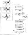
- FIG. 5 is a diagram showing an example of an operation flowchart in the case where a failure occurs in part during operation of this system in the system using the distributed control device shown in FIG. 1 to FIG. .
- step S01 in FIG. 5 the system is activated, and at step S02, initialization for system operation is performed, and the system transitions to the system normal operation at step S03.
- the failure point determination unit 31 of the reconfiguration control units 21, 22 and 23 performs failure diagnosis of each of the CPUs 1, 2 and 3 and It is determined in step S05 whether a failure occurs in the CPUs 1, 2 and 3.
- step S05 if no failure occurs in each of the CPUs 1, 2 and 3, the process proceeds from step S05 to step S03 to continue the normal operation of the system.
- step S05 If it is determined in step S05 that the failure point determination unit 31 of the reconfiguration control unit 21, 22 or 23 has caused a failure in any one of the CPUs 1, 2 or 3, the process proceeds to step S11.
- data diagnosis means data diagnosis unit of the shared data diagnosis unit 27 55 diagnoses the data stored in the memory 12 and the data input from the shared data diagnosis unit 28.
- Data diagnosis performed in step S12 is performed using parity, ECC (error correction code), CRC (cyclic redundancy check), data matching, and the like.
- step S13 it is determined in step S13 whether the data is correct. If any data is correct in step S13, the process proceeds to step S14. In this example, the CPU 2 substitutes the CPU 1 and performs the system degeneration operation in step S15.
- step S13 if one of the data is incorrect at step S13, the process goes to step S21 to correct the incorrect data, and then the process goes to step S14 to perform CPU substitution processing.
- the degeneration operation is a case where the automatic driving operation is changed to the degeneration operation, the important operation of the automatic driving operation is maintained while the other automatic driving operation is not performed.
- the automatic driving operation is to operate with restriction.
- FIG. 6 shows a case where in the system using the distributed control device shown in FIG. 1 to FIG.
- FIG. 6 is a diagram showing an example of an operation flowchart of FIG.
- the operation flow chart of FIG. 6 is different from the operation flow chart shown in FIG. 5 in that the return operation of the CPU 1 of steps S16 to S18 is added after step S15.
- steps S01 to S15 are the same as the operations shown in FIG.
- step S16 the return operation of the CPU 1 is performed.
- the CPU 2 outputs a reset signal to the CPU 1.
- step S17 a failure of the CPU 1 is detected. This can be performed by the CPU 2. Then, in step S18, if it is possible to confirm that the CPU 1 has recovered by whether or not the failure is detected in the CPU 1 in step S17, all of the CPU 1, CPU 2 and CPU 3 operate normally, and transition to system normal operation in step S03. Do.
- step S18 the system transitions to the system degeneration operation in step S15 again.
- step 16 If the return operation of the CPU 1 in step 16 is attempted a plurality of times and return is not made, the entire system may be safely stopped.
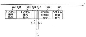
- FIG. 7A is a timing chart of the operation in the distributed control device of the first embodiment shown in FIGS. 1 to 6, and FIG. 7B is an example of a timing chart of the operation of the distributed control device to which the present invention is not applied.
- step S03 shown in FIG. 7A to the system degeneration operation of step S15 correspond to each step of the operation flowchart shown in FIG.
- determination step of step S05 and step S13 is abbreviate
- step S11 a failure of the CPU 1 is detected, the data diagnosis in step S12 and the incorrect data correction in step S21 are performed, the substitution process in step S14 is performed, and the transition to the degeneration operation in step S15 is performed.
- the data diagnosis in step S12 and the unauthorized data correction in step S21 can be performed by the hardware of the CPU by the distributed control device of the present invention, and can be performed at a very high speed. take time t a is short.
- step S05 and step S13 are also omitted in FIG. 7B.
- the timing chart of FIG. 7B as compared to the timing chart of FIG. 7A, a data diagnosis of the memory 2 and the memory 3 in step S12, a long time t b according to bad data correction step S21.
- the data diagnosis and data correction functions by the hardware mainly the data diagnosis means 55 (data diagnosis unit) in the distributed control device of the present invention are not applied and executed by processing by software. It is for.
- the distributed control device according to the first embodiment of the present invention, even if a failure occurs in part of the system, it is possible to shift to the degeneration operation at high speed by the data diagnosis and correction mechanism by hardware. .
- the first embodiment of the present invention it is possible to realize a distributed control device capable of improving the safety and the correctness by avoiding the occurrence of a single failure point and reducing the transition delay time to the degeneration operation. Can.
- the common data diagnosis unit 27 is connected to the memory 12 and the common data diagnosis unit 28 is connected to the memory 13
- the common data diagnosis unit 27 is connected to the memory 12 and the memory 13.
- the common data diagnostic unit 28 may also be connected to the memory 12 and the memory 13.
- the number of CPUs and memories is three, but the number of CPUs and memories may be four or more.
- the recovery operation of the CPU 1 is performed after the system degeneration operation is performed, the recovery operation of the CPU 1 is performed before the degeneration operation is performed.
- the operation of the CPU 1 may be restored without performing the degeneration operation. In this case, when it is determined that recovery of the CPU 1 is difficult, the degeneracy operation is performed.
- FIG. 8 is a schematic block diagram of the distributed control device according to the second embodiment.
- the second embodiment is different from the first embodiment shown in FIG. 1 in that nonvolatile memories 70 (first nonvolatile memory) and 71 (second nonvolatile memory) are added.
- a non-volatile memory 70 is connected to a bus between the reconfiguration control unit 22 and the shared data diagnosis unit 27.
- This non-volatile memory 70 is shared data from the reconfiguration control unit 22 when a failure occurs in the CPU 2.
- Information of write data to be transmitted to the diagnosis unit 27 is held (stored).
- a non-volatile memory 71 is connected to a bus between the reconfiguration control unit 23 and the shared data diagnosis unit 28. This non-volatile memory 71 performs shared data diagnosis from the reconfiguration control unit 23 when a failure occurs in the CPU 3 It holds (stores) information on write data to be sent to the unit 28.
- the non-volatile memories 70 and 71 As described above, by adding the non-volatile memories 70 and 71 to the distributed control device to hold information when a failure occurs, the entire system is stopped due to the influence of the failure and the volatile memory Even if the contents are not held, etc., the contents held (stored) in the non-volatile memories 70 and 71 can be checked later to increase the possibility that the cause of the system stop can be confirmed, which is useful for system maintenance. It becomes possible.
- non-volatile memory 70 is connected to the reconfiguration control unit 22 and the non-volatile memory 71 is connected to the reconfiguration control unit 23 in the example of the second embodiment, the non-volatile memory 70 is connected to the reconfiguration control units 22 and 23. The connection may be made, and the non-volatile memory 71 may also be connected to the reconfiguration control units 22 and 23.
- the number of CPUs and memories is three in the example of the second embodiment, the number may be four or more.
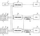
- FIG. 9 is a schematic explanatory diagram of the distributed control device according to the third embodiment.
- the CPU 4 operation control unit
- the CPU 5 operation control unit having a lock step configuration in which the CPU is duplicated for the CPU 2 and the CPU 3 in the first embodiment.
- the point I made was different.
- the other configuration of the third embodiment is similar to that of the first embodiment.
- the lockstep CPU 4 includes the CPU core 6 and the CPU core 7.
- the calculation result of the CPU 6 and the calculation result of the CPU 7 are collated by the collator 80, and a failure occurs in either of the CPU cores 6 and 7. Then, the failure detection signal is output to the outside of the lock step CPU 4.
- the lockstep CPU 5 also includes the CPU core 8 and the CPU core 9 as in the lockstep CPU 4 and collates the calculation result of the CPU core 8 with the calculation result of the CPU core 9 by the collator 81. If a failure occurs in the system, the failure detection signal is output to the outside of the lockstep CPU 5.
- the CPU 4 or 5 becomes the master CPU instead of the CPU 1, a failure of the master CPU itself can be detected, and the safety can be further improved.
- the lockstep CPU has been described as having two CPUs 4 and 5.
- the lockstep CPU may be one of three CPUs (CPU1, CPU4, and CPU5). Good.
- all CPUs including the CPU 1 may be configured as lock step CPUs.
- FIGS. 10A and 10B examples of data formats used in the present invention will be described using FIGS. 10A and 10B.
- This data format can be common to the first to third embodiments.
- FIG. 10A is a diagram showing an example of a data frame output from the reconfiguration control units 22 and 23 in the distributed control device of the present invention to a control target device.
- This data frame includes a 1-bit SOF (Start of Frame) 200, a 2-bit ID (Identification) 201, an 8-bit data 202, a 4-bit CRC (203), and a 3-bit CPU in this order from the left in FIG. 10A.
- the values of the data 200 to 205 are represented by binary numbers of 0 and 1, respectively.
- the data frame shown in FIG. 10A is a frame in which the value of ID 201 is 10 and the frame is output from CPU 2, the value of data 202 is 10111110, the value of CRC 203 for data 202 is 1110, and faulty CPU 204 is 000. It indicates that no failure has occurred in any of the CPUs.
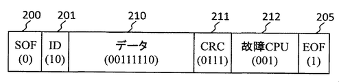
- FIG. 10B is a diagram showing an example of a data frame when a failure occurs, and the value of data 210 is 00111110 and the value of CRC 211 is 0111 as compared to the data frame shown in FIG. 10A. The place where the value of is 001 is different.
- a fault occurs in the CPU 1 due to the value of the faulty CPU 212, and as a result, the value of the data 210 is affected by the fault, and the value of the CRC 211 for the data 210 is different.
- FIG. 11 is a diagram showing an example in which the distributed control system according to the fourth embodiment is applied to a vehicle control system in a vehicle control system.
- the interior of a car 500 is configured in a form in which a plurality of electronic control units are connected.
- This automobile 500 includes an autonomous driving ECU (Automating Driving ECU, AD-ECU) 511 receiving the inputs of the sensors 514 and 515, and a power train ECU 510 for operating the automobile 500 by operating the front wheels 501 and 502.
- Vehicle motion control devices Vehicle Motion Control, VMC 512 and 513 for transmitting a traveling command from the AD-ECU 511 to the power train ECU 510 are connected as shown in FIG.
- the AD-ECU 511 includes a CPU 511a, a reconfiguration control unit 511b, and a local memory 511c (Local Memory, LM).
- the VMC 512 includes a CPU 512a, a shared data diagnosis unit 512b, a reconfiguration control unit 512c, and an LM 512d.
- the VMC 513 includes a CPU 513a, a shared data diagnosis unit 513b, a reconfiguration control unit 513c, and an LM 513.
- the AD-ECU 511, the VMCs 512 and 513, and the power train ECU 510 are connected to one another and perform coordinated operation to perform automatic operation control.
- the automatic driving ECU 511 corresponds to the CPU 1
- the vehicle motion control device 512 corresponds to the CPU 2
- the reconfiguration control unit 22 corresponds to the shared data diagnosis unit 27 and the memory 12 of FIG. It corresponds.
- a vehicle motion control device 513 corresponds to the CPU 3, the reconfiguration control unit 23, the shared data diagnosis unit 28, and the memory 13 in FIG. 1.
- the VMCs 512 and 513 connected to the AD-ECU 511 detect that the failure occurs in the AD-ECU 511, respectively.
- the VMC 512 quickly performs the degeneration operation of the AD-ECU 511 by diagnosing data shared by the LM 511 c of the AD-ECU 511 and the LM 512 d of the VMC 512 by the reconfiguration control unit 512 c of the VMC 512.
- the AD-ECU 511, VMCs 512 and 513, and the power train ECU 510 can continue the minimum operation while shifting to the degeneracy operation, and continue or stop the rotation of the front wheels 501, 502 according to the surrounding conditions. Secure the safe operation of the entire automobile system.
- FIG. 12 is a diagram showing an example where the distributed control device according to the fifth embodiment is applied to an operation control device in an industrial control system.
- this industrial control system includes a computer 600 for overall control of the system, a controller 631 controlled by the computer 600, a programmable logic controller 632 for controlling the display plate 640, and programmable logic for controlling the actuator 641. And a controller 633.
- the controller 631 and the programmable logic controllers 632, 633 are connected via the control bus 637, respectively.
- the controller 631 is configured by combining a plurality of modules such as a CPU module 601, a memory module 611, and a reconfiguration control module 621.
- the programmable logic controller 632 is also configured by combining a plurality of modules in the same manner as the controller 631.
- the programmable logic controller 632 is configured by combining the CPU module 602, the memory module 612, the reconfiguration control module 622, and the like.
- the programmable logic controller 633 also includes a CPU module 603, a memory module 613, a reconfiguration control module 623, and the like.
- the controller 631 corresponds to the CPU 1, the reconfiguration control unit 21, and the memory 11 in FIG. 1
- the programmable logic computer 632 corresponds to the CPU 2, the reconfiguration control unit 22, the shared data diagnosis unit 27, and the memory 12 in FIG. 1.
- the programmable computer 633 corresponds to the CPU 3, the reconfiguration control unit 23, the shared data diagnosis unit 28, and the memory 13 in FIG. 1. However, in FIG. 12, the shared data diagnosis unit is omitted.
- the programmable logic controllers 632 and 633 detect that the failure has occurred in the controller 631 via the control bus 637.
- the reconfiguration control unit 622 diagnoses data shared by the memory module 612 of the programmable logic controller 632 and the memory module 611 of the control controller 631 to allow the programmable logic controller 632 to perform the degeneration operation of the controller 631. It is done promptly by
- the controller 631 and the programmable logic controllers 632, 633 can continue the minimum operation while shifting to the degeneracy operation, and by continuing or safely stopping the operation of the display plate 640 and the actuator 641, the industrial system As a whole, safe operation can be secured.
- the distributed control apparatus according to the fifth embodiment of the present invention to the operation control apparatus in the industrial control system, even if a failure occurs in some of the apparatuses constituting the industrial control system, the system as a whole can It is possible to maintain safety while immediately shifting to the degeneracy operation.
- the present invention is not limited to the embodiments described above, but includes various modifications.
- the embodiments described above are described in detail in order to explain the present invention in an easy-to-understand manner, and are not necessarily limited to those having all the configurations described.
Landscapes
- Engineering & Computer Science (AREA)
- Theoretical Computer Science (AREA)
- Physics & Mathematics (AREA)
- Computer Hardware Design (AREA)
- General Engineering & Computer Science (AREA)
- General Physics & Mathematics (AREA)
- Mathematical Physics (AREA)
- Software Systems (AREA)
- Quality & Reliability (AREA)
- Hardware Redundancy (AREA)
Abstract
単一故障点の発生を回避し、縮退動作への移行遅延時間を原減少し、安全性及び信頼正性を向上可能な分散制御装置が実現される。分散制御装置はCPU1の演算結果をCPU2とCPU3とが使用して処理を行うため、再構成制御部21、22及び23が、CPU1、2及び3と各メモリ11、12及び13との間に接続され、再構成制御部21、22及び23どうしも互いに接続される。再構成制御部22とメモリ12との間には共有データ診断部27が接続され、再構成制御部23とメモリ13との間には共有データ診断部28が接続される。CPU1で故障が発生した場合、CPU1の故障発生を検出し、CPU2とCPU3での縮退動作に移行するためにメモリ12とメモリ13のデータ診断を行う。いずれのデータも正しかった場合CPU2がCPU1を代替しシステム縮退動作を行う。
Description
本発明は、分散制御装置に関する。
半導体プロセスの微細化に伴い、CPU(Central Processing Unit、中央演算処理装置)の高性能化や、RAM(Randam Access Memory、主記憶、メモリ)の高速・大容量化が可能になってきた。
これら半導体デバイスの進歩により、特に、産業分野や自動車分野等においては、従来では成し得なかった様々な機能を実現するための取り組みが始まっている。
例えば、産業分野では現実世界に分散して配置した大量の装置から稼働データを収集して仮想世界上で分析し、より良い制御出力を現実世界へフィードバックさせるIoT(Internet of Things)への取り組みが盛んである。
また、自動車分野ではAI(Artificial Intelligence、人工知能)を自動車の制御装置に組込むことで、自動車システムに認識機能と制御機能を持たせて自動運転を実現しようとするための取り組みが行われている。
産業分野でIoTを実現するには産業システム全体を構成するデバイス、PLC(Programmable Logic Controller)、クラウドなどの各階層にてそれぞれが分散処理を行い、相互に情報を通信して現実世界と仮想世界を有機的に接続する必要がある。
また、将来の自動車システムではAIを実現する機能や外界認識機能、モーターやステアを操作するアクチュエーション機能などを複数の電子制御ユニット(Electronic Control Unit、ECU)に割り当て、分散制御することで自動運転を実現する構成を採ることが考えられる。
このような産業システムや自動車システムにおいて、機能が高度化しシステムが複雑化していく場合に課題となるのは安全性と信頼性の確保である。特に、人命が関わるシステムにおいて、システムの一部で異常や故障が発生した場合にその影響がシステム全体に波及して想定通りの制御ができなくなり、その結果人命が損なわれるようなシステムは許容されない。
そのため、このような分野のシステムでは異常や故障が発生したことを検出し対策する仕組みを取ることが一般的である。
本技術分野の背景技術として、例えば、特許文献1には、複数のマイクロプロセッサにより分散処理が行われる分散処理機能を持つマイクロプロセッサ応用装置が記載されている。
特許文献1に記載のマイクロプロセッサ応用装置は、複数のマイクロプロセッサの一部が故障しても、装置全体として縮退運転により動作を継続することを目的としている。そして、各マイクロプロセッサの故障の有無の組合せで決定される装置構成毎に、正常な各マイクロプロセッサで実行すべきプログラムが格納されたプログラムメモリと、各マイクロプロセッサの異常を検出して装置の初期化を行うための初期化手段と、プログラム割当て手段とを備えている。
そして、プログラム割当て手段は、上記複数のマイクロプロセッサの1つがマスタプロセッサとなって初期化手段の異常検出結果をもとに装置構成の変化を判別し、新たな装置構成に固有のプログラムをプログラムメモリから取り出してそれぞれ対応する正常なマイクロプロセッサに割り当てることとしている。
ところで、従来の複数のマイクロプロセッサとメモリと初期化手段とを有する分散処理機能を持つ技術について、本発明者が検討した結果、以下のようなことが明らかとなった。
特許文献1に記載の技術では、複数のマイクロプロセッサが共有している共有メモリおよび初期化制御部は一組ずつしかなく、これらの部位が故障した場合には、単一故障点となる可能性があり、これらの部位が故障した場合の対策のための構成及び動作が明示されていない。
また、マスタCPUが共有メモリを介して縮退時のソフトウェアをスレーブCPUに転送する必要があり、そのための時間が要求され、通常動作から縮退動作へ切り替えるために時間がかかっていた。
このため、リアルタイム性が要求されるような産業システムや自動車システムへの適用が困難であるという問題があった。
本発明の目的は、単一故障点の発生を回避し、縮退動作への移行遅延時間を原減少し、安全性及び信頼正性を向上可能な分散制御装置を実現することである。
上記目的を達成するため、本発明は次のように構成される。
分散制御装置において、第1の動作制御部と、上記第1の動作制御部に接続された第1の再構成制御部と、上記第1の再構成制御部に接続された第1のメモリと、第2の動作制御部と、上記第2の動作制御部に接続された第2の再構成制御部と、上記第2の再構成制御部に接続された第2のメモリと、上記第2の再構成制御部及び上記第2のメモリに接続された第1の共有データ診断部と、第3の動作制御部と、上記第3の動作制御部に接続された第3の再構成制御部と、上記第3の再構成制御部に接続された第3のメモリと、上記第3の再構成制御部及び上記第3のメモリに接続された第2の共有データ診断部と、を備え、上記第2のメモリはこの第2の専用メモリ空間、上記第1のメモリとの共有メモリ空間及び上記第3のメモリとの共有メモリ空間を有し、上記第3のメモリはこの第3のメモリの専用メモリ空間、上記第1のメモリとの共有メモリ空間及び上記第2のメモリとの共有メモリ空間を有し、上記第1の共有データ診断部は上記第2のメモリにおける上記第1のメモリとの共有空間に格納されたデータを診断し、誤ったデータを正しいデータに書き換え、上記第2の共有データ診断部は上記第3のメモリにおける上記第1のメモリとの共有メモリ空間に格納されたデータを診断し、誤ったデータを正しいデータに書き換える。
本発明によれば、産業分野や自動車分野などのシステムにおいて、単一故障点の発生を回避し、縮退動作への移行遅延時間を原減少し、安全性及び信頼正性を向上可能な分散制御装置を実現することができる。
以下、本発明の実施例を、図面を用いて説明する。
(実施例1)
図1から図7A及び図7Bを用いて、本発明の実施例1を説明する。
図1から図7A及び図7Bを用いて、本発明の実施例1を説明する。
図1は、本発明の実施例1による分散制御装置の概略構成図である。
図1に示した例は、CPU1(第1の動作制御部)及びメモリ11(第1のメモリ)と、CPU2(第2の動作制御部)及びメモリ12(第2のメモリ)と、CPU3(第3の動作制御部)及びメモリ13(第3のメモリ)との組み合わせによって分散処理を行う分散制御装置の例である。
この分散制御装置の例では、CPU1の演算結果をCPU2とCPU3とが使用して処理を行う構成を採っており、そのための再構成制御部21(第1の再構成制御部)、再構成制御部22(第2の再構成制御部)及び再構成制御部23
(第3の再構成制御部)が、各CPU1、2及び3と各メモリ11、12及び13との間に接続されており、各再構成制御部21、22及び23どうしも互いに接続されている(データを相互通信する)。
(第3の再構成制御部)が、各CPU1、2及び3と各メモリ11、12及び13との間に接続されており、各再構成制御部21、22及び23どうしも互いに接続されている(データを相互通信する)。
さらに、CPU2に接続された再構成制御部22とメモリ12との間には共有データ診断部27(第1の共有データ診断部)が接続されている。同様に、CPU3に接続された再構成制御部23とメモリ13との間には共有データ診断部28(第2の共有データ診断部)が接続されている。共有データ診断部27と共有データ診断部28とは、データを相互通信する構成となっている。
図2は、図1に示した再構成制御部22の詳細な構成の一例を示す図である。
図2において、再構成制御部22には、CPU2からアドレス101、ライトデータ102、コマンド103及び故障検出信号132(故障検出信号番号2)が入力される。また、再構成制御部22には、別の再構成制御部21から故障検出信号131(故障検出信号番号1)が入力され、再構成制御部23から故障検出信号133(故障検出信号番号3)が入力される。
共有空間判定部30は、メモリ12においてCPU2が使用するメモリ空間とCPU1およびCPU3とで共有するメモリ空間とを判定するもので、この例では制御システムで動作させるソフトウェアによってどのメモリ空間を共有するかが予め決定されている。
デマルチプレクサ40は、共有空間判定部30が出力する共有空間判定信号150の結果によってアドレス101の出力先をアドレス111とアドレス(共有)121とに切り替える。アドレス101がCPU2のメモリ空間であればデマルチプレクサ40はアドレス101をアドレス111としてメモリ12に出力し、アドレス101がCPU1またはCPU3とで共有するメモリ空間であればデマルチプレクサ40はアドレス101をアドレス(共有)121として共有データ診断部27に出力する。
同様に、アドレス101がCPU2のメモリ空間であればデマルチプレクサ41はライトデータ102をライトデータ112としてメモリ12に出力し、デマルチプレクサ42はコマンド103をコマンド113としてメモリ12に出力する。
また、アドレス101がCPU1またはCPU3で共有するメモリ空間であれば、デマルチプレクサ41はライトデータ102をライトデータ(共有)122として共有データ診断部27に出力し、デマルチプレクサ42はコマンド103をコマンド(共有)123として共有データ診断部27に出力する。
なお、共有領域判定信号150は、後述するようにメモリ12に出力される。
再構成制御部22へは、メモリ12からリードデータ114が入力され、共有データ診断部27からリードデータ(共有)124が入力される。
共有空間判定信号150の結果によって、アドレス101がCPU2のメモリ空間であれば、セレクタ46はリードデータ114をリードデータ104として選択してCPU2に出力する。
アドレス101がCPU1またはCPU3とで共有するメモリ空間であればセレクタ46はリードデータ(共有)124をリードデータ104として選択してCPU2に出力する。
故障箇所判定部31は、CPU1の再構成制御部21から入力されるCPU1の故障検出信号131と、CPU2から入力されるCPU2の故障検出信号132と、CPU3の再構成制御部23から入力されるCPU3の故障検出信号133との情報から、CPU1、CPU2及びCPU3のいずれのCPUで故障が発生したかを検出する。
そして、故障箇所判定部31は、故障したCPUに応じてデータ診断要求信号137を共有データ診断部27に出力する。
図1に示した再構成制御部23も、図2に示した再構成制御部22と同様の構成となっている。また、図1に示した共有データ診断部27とは接続されていない再構成制御部21は、図2の再構成制御部22からアドレス(共有)121、ライトデータ(共有)122、コマンド(共有)123、リードデータ(共有)124、故障箇所判定部31などを除いた形で、再構成御部部22と同様な構成とすることができる。
図3は、図1に示した共有データ診断部27の構成の一例を示す図である。
図3において、共有データ診断部27には、再構成制御部22からアドレス(共有)121、ライトデータ(共有)122、コマンド(共有)123及びデータ診断要求信号137が入力される。また、共有データ診断部27には、別の共有データ診断部28からリードデータ(共有)125が入力される。
アドレスバッファ51は、アドレス(共有)121を複数保持することが可能な構成であり、保持したアドレス(共有)121の内容を順にアドレス(共有)126としてメモリ12に出力する。
同様に、ライトデータバッファ52は、ライトデータ(共有)122を複数保持して順にライトデータ(共有)127としてメモリ12に出力する。また、コマンドバッファ53は、コマンド(共有)123を複数保持して順にコマンド(共有)128としてメモリ12に出力する。
故障診断ステートマシン56は、データ診断要求信号137の値によってCPU1~3のうちのいずれかのCPUで故障発生を検出したタイミングにおいて、アドレス(共有)126が示すメモリ空間にコマンド(共有)128によってライトされたライトデータ(共有)127を診断することを制御するものである。
CPU1~3のうちのいずれかのCPUでの故障発生時に故障診断ステートマシン56はデータ診断開始信号138を有効にしてデータ診断手段55に送信する。
データ診断開始信号138を受けたデータ診断手段55は、メモリ12から入力されたリードデータ(共有)124の値と別の共有データ診断部28から入力されたリードデータ(共有)125の値を診断し、CPUの故障による影響でいずれかのリードデータが不正な値になっていないかどうかを診断し、誤ったデータを正しいデータに書き換えて、データ診断結果54として共有データ診断部28へ出力する。
なお、データ診断手段55におけるデータの故障検出手段としては、パリティ、ECC(Error Correction Code)、CRC(Cyclic Redundancy Check)、データ照合などの技術が知られており、これらを使用することができる。
図1に示した共有データ診断部28も図3の共有データ診断部27と同様の構成である。
図4は、図1に示したメモリ12の詳細な構成の一例を示す図である。
図4において、メモリ12には、再構成制御部22からアドレス111、ライトデータ112、コマンド113及び共有空間判定信号150が入力され、共有データ診断部27からアドレス(共有)126、ライトデータ(共有)127及びコマンド(共有)128が入力される。
共有空間判定信号150の結果によって、セレクタ60はアドレス111とアドレス(共有)126のうちの選択したアドレスをアドレス141としてメモリセル15に出力する。セレクタ61はライトデータ112とライトデータ(共有)127のうちの選択したライトデータをライトデータ142としてメモリセル15に出力する。
また、セレクタ62はコマンド113とコマンド(共有)128のうちの選択したコマンドをコマンド143としてメモリセル15に出力する。
また、共有空間判定信号150の結果によって、デマルチプレクサ66はリードデータ144をリードデータ114として再構成制御部22へ、もしくはリードデータ(共有)124として共有データ診断部27へ出力する。
メモリセル15は、メモリ12を構成する中でデータのライトとリードが可能な部位である。メモリセル15へ入力されるコマンド143がライトの場合はアドレス141で示されるメモリ空間にライトデータ142をライトし、メモリセル15へ入力されるコマンド143がリードの場合はアドレス141で示されるメモリ空間からリードデータ144をリードする。
図4におけるメモリセル15の#2で示したメモリ空間17は、CPU2が使用する専用メモリ空間であり、メモリ空間17へのアクセスではアドレス111、ライトデータ112、コマンド113、リードデータ114を使用する。
一方、メモリセル15の#12で示したメモリ空間18はCPU2がCPU1と共有して使用する共有メモリ空間であり、#23で示したメモリ空間19はCPU2がCPU3と共有して使用する共有メモリ空間である。
これらのメモリ空間18、19へのアクセスではアドレス(共有)126、ライトデータ(共有)127、コマンド(共有)128、リードデータ(共有)124を使用する。
図1に示したメモリ13も図4のメモリ12と同様の構成である。また、図1に示した共有データ診断部27が接続されていないメモリ11は、図4のメモリ12からアドレス(共有)126、ライトデータ(共有)127、コマンド(共有)128、リードデータ(共有)124などを除いた形で構成することができる。
図5は、図1から図4で示した分散制御装置を用いたシステムにおいて、このシステムが動作中に一部で故障が発生し縮退動作に移行する場合の動作フローチャートの一例を示す図である。
図5のステップS01にてシステムを起動し、ステップS02にてシステム動作のための初期設定を行って、ステップS03のシステム通常動作に遷移する。
システムの通常動作中は、例えば制御周期の中で定期的にステップS04にて再構成制御部21、22及び23の故障個所判定部31は、各CPU1、2及び3の故障診断を行って各CPU1、2及び3に故障が発生していないかをステップS05にて判定する。
ステップS05において、各CPU1、2及び3に故障が発生していなければ、ステップS05からステップS03に遷移して、システムの通常動作を続ける。
ステップS05にて、再構成制御部21、22又は23の故障個所判定部31が、いずれかのCPU1、2又は3で故障が発生したと判断した場合、ステップS11に遷移する。図5の例ではステップS11においてCPU1で故障が発生したことを検出し、CPU2とCPU3での縮退動作に移行するためにステップS12にて、共有データ診断部27のデータ診断手段(データ診断部)55が、メモリ12に格納されたデータと共有データ診断部28から入力されたデータとの診断を行う。
ステップS12にて行うデータ診断は、パリティ、ECC(誤り訂正符号)、CRC(巡回冗長検査)、データ照合などを用いて行われる。
ステップS12のデータ診断の結果、データが正しいか否かの判断がステップS13にて行われる。ステップS13にて、いずれのデータも正しかった場合はステップS14に遷移し、この例ではCPU2がCPU1を代替し、ステップS15にてシステム縮退動作を行う。
一方、ステップS13にていずれかのデータが不正であった場合はステップS21に遷移し、不正データを訂正したのち、ステップS14に遷移してCPUの代替処理を行う。
なお、この図5の動作フローチャートではCPU1が故障しCPU2で代替する例で示したが、CPU3が代替してよい。また、CPU2もしくはCPU3が故障した場合の動作も、図5に示した動作フローチャートと同様の動作フローチャートで示すことができる。
ここで、縮退動作とは、自動運転動作を縮退動作に変更する場合であれば、自動運転動作のうちの、重要な動作を維持しつつ、その他の自動運転動作は行わない動作とするように、自動運転動作に制限を設けて動作させることである。
図6は、図1から図4で示した分散制御装置を用いたシステムにおいて、システムが動作中に一部で故障が発生し縮退動作に移行した後、故障部位を復帰させて再び動作する場合の動作フローチャートの一例を示した図である。
図6の動作フローチャートは、図5に示した動作フローチャートと比較して、ステップS15の後にステップS16~S18のCPU1の復帰動作を追加している。
断線などのハードウェア故障であれば復帰できないが、ソフトエラーなどの一時的な故障であればCPUのリセットなどにより復帰できる場合がある。このため、故障したCPUにリセット信号を入力し、復帰動作を行い、復帰したならば、再び、動作を行わせることが可能である。
図6において、ステップS01からS15までには、図5に示した動作と同様であるので、説明は省略する。
ステップS15に続くステップS16において、CPU1の復帰動作が行われる。例えば、CPU2がCPU1にリセット信号を出力する。
次に、ステップS17において、CPU1の故障を検出する。これはCPU2が実行することができる。そして、ステップS18において、ステップS17のCPU1に故障が検出されたか否かにより、CPU1が復帰したことを確認できれば、CPU1、CPU2、CPU3のいずれも正常に動作するのでステップS03のシステム通常動作に遷移する。
一方、ステップS18にてCPU1が復帰したことを確認できない場合は再びステップS15のシステム縮退動作に遷移する。
ステップ16のCPU1の復帰動作を複数回試みて復帰しない場合は、システム全体を安全に停止させるようにしてもよい。
なお、この図6の動作フローチャートではCPU1が故障しCPU2で代替する例で示したが、CPU2もしくはCPU3が故障した場合でも同様の動作フローチャートで示すことができる。
図7Aは、図1から図6に示した実施例1の分散制御装置における動作のタイミングチャートであり、図7Bは、本発明を適用しない分散制御装置の動作のタイミングチャートの一例である。
図7Aに示したステップS03のシステム通常動作からステップS15のシステム縮退動作までは、図5で示した動作フローチャートの各ステップに対応している。なお、ステップS05とステップS13の判定ステップは、省略して図示している。
図7Aに示した例では、最初のステップS03とステップS04においてCPUで故障が発生していない通常動作を行っているが、2回目のステップS04の各CPUの故障診断においてCPU1で故障が発生し、ステップS11に遷移してCPU1の故障を検出し、ステップS12のデータ診断、ステップS21の不正データ訂正を経てステップS14の代替処理を行い、ステップS15の縮退動作に遷移する。
ここで、ステップS12のデータ診断とステップS21の不正データ訂正については、本発明の分散制御装置によって、CPUのハードウェアで実行するため非常に高速に行うことができ、ステップS12及びS21の動作にかかる時間taは短い。
図7Bに示した本発明を適用しない分散制御装置の動作のタイミングチャートにおいては、図7Aと同様に、ステップS03のシステム通常動作からステップS15のシステム縮退動作までは、図5で示した動作フローチャートの各ステップに対応している。なお、図7Aと同様に、図7Bにおいても、ステップS05とステップS13の判定ステップは省略して図示している。
図7Bのタイミングチャートは図7Aのタイミングチャートと比較して、ステップS12のメモリ2及びメモリ3のデータ診断と、ステップS21の不正データ訂正にかかる時間tbが長い。図7Bに示した例は、本発明の分散制御装置におけるハードウェア(主としてデータ診断手段55(データ診断部))によるデータ診断とデータ訂正機能を適用しておらずソフトウェアによる処理で実行しているためである。
つまり、マスタCPUが共有メモリを介して縮退時のソフトウェアをスレーブCPUに転送するための時間が必要であり、通常動作から縮退動作へ切り替えるために時間がかかり、時間tbが長い時間となることとなる。
これに対して、本発明の実施例1による分散制御装置によって、システムの一部で故障が発生した場合でもハードウェアによるデータの診断と訂正機構により高速に縮退動作に移行することが可能となる。
従って、リアルタイム性と高信頼性が必要とされるシステムを実現することが可能になる。
すなわち、本発明の実施例1によれば、単一故障点の発生を回避し、縮退動作への移行遅延時間を減少させ、安全性及び信頼正性を向上可能な分散制御装置を実現することができる。
また、実施例1の例では共通データ診断部27をメモリ12に接続し、共通データ診断部28をメモリ13に接続する形で説明したが、共通データ診断部27をメモリ12及びメモリ13に接続し、共通データ診断部28もメモリ12及びメモリ13に接続する構成としてもよい。
また、実施例1の例ではCPUおよびメモリの数を3として説明したが、CPUおよびメモリの数を4以上の数で実装することもできる。
さらに、実施例1の例では、図6に示したように、システムの縮退動作を実行した後に、CPU1の復帰動作を行うように構成したが、縮退動作を実行する前に、CPU1の復帰動作を行い、縮退動作を行うことなく、CPU1の動作を復帰させる構成としてもよい。この場合、CPU1の復帰が困難と判断した場合には、縮退動作を行うように構成される。
(実施例2)
次に、本発明の実施例2について説明する。
次に、本発明の実施例2について説明する。
図8は、実施例2による分散制御装置の概略構成図である。
実施例2は、図1に示した実施例1と比較して、不揮発メモリ70(第1の不揮発メモリ)及び71(第2の不揮発メモリ)を追加した点が異なっている。
図8において、再構成制御部22と共有データ診断部27との間のバスに不揮発メモリ70が接続され、この不揮発メモリ70は、CPU2で故障が発生したときに再構成制御部22から共有データ診断部27へ送信するライトデータの情報を保持(格納)するものである。
また、再構成制御部23と共有データ診断部28との間のバスに不揮発性メモリ71が接続され、この不揮発メモリ71は、CPU3で故障が発生したときに再構成制御部23から共有データ診断部28へ送信するライトデータの情報を保持(格納)するものである。
このように、分散制御装置に不揮発メモリ70及び71を追加して故障が発生したときの情報を保持しておく構成とすることで、故障の影響などでシステム全体が停止して揮発性メモリの内容が保持されない場合などでも、あとから不揮発メモリ70及び71に保持された(格納された)内容を確認して、システムが停止した原因を確認できる可能性が高まり、システムの保守に役立てることが可能となる。
以上のように、実施例2によれば、実施例1により得られる効果の他、上述したような効果を得ることができる。
なお、実施例2の例では不揮発メモリ70を再構成制御部22に接続し、不揮発メモリ71を再構成制御部23に接続する構成としたが、不揮発メモリ70を再構成制御部22及び23に接続し、不揮発メモリ71も再構成制御部22及び23に接続する構成としてもよい。
さらに、実施例2の例ではCPUおよびメモリの数を3として説明したが、4以上の様々な数で実装してもよい。
(実施例3)
次に、本発明の実施例3について説明する。
次に、本発明の実施例3について説明する。
図9は、実施例3による分散制御装置の概略説明図である。
実施例3は、図1に示した実施例1と比較して、実施例1におけるCPU2及びCPU3について、CPUを2重化したロックステップ構成のCPU4(動作制御部)及びCPU5(動作制御部)にした点が異なっている。実施例3の他の構成は、実施例1の構成と同様となっている。
図9において、ロックステップCPU4は、CPUコア6及びCPUコア7を備え、CPU6の演算結果とCPU7の演算結果とを、照合器80で照合し、CPUコア6及び7のいずれかで故障が発生したら故障検出信号をロックステップCPU4の外部へ出力する構成である。
ロックステップCPU5もロックステップCPU4と同様に、CPUコア8及びCPUコア9を備え、CPUコア8の演算結果とCPUコア9の演算結果とを照合器81で照合し、CPUコア8及び9のいずれかで故障が発生したら故障検出信号をロックステップCPU5の外部へ出力する構成である。
なお、ロックステップ動作中の照合手法は、公知の技術である。
このように、分散制御装置を構成するCPUの一部(CPU4とCPU5)をロックステップCPUにすることで、分散制御装置で故障が発生した場合の故障検出を即座に行い縮退動作へ高速に遷移することが可能となり、高信頼性が要求される分散制御装置を実現することが可能になる。
また、仮に、CPU4又は5がCPU1に代わってマスタCPUとなった場合、マスタCPU自身の故障を検出することができ、安全性をさらに向上することができる。
以上のように、実施例3によれば、実施例1により得られる効果の他、上述したような効果を得ることができる。
なお、実施例3の例ではロックステップCPUをCPU4とCPU5の2つにした形で説明したが、ロックステップCPUを、3つのCPU(CPU1、CPU4、CPU5)のうちのいずれか1つとしてもよい。
また、CPU1を含めた全てのCPUをロックステップCPUとした構成としてもよい。
また、実施例3の例ではCPUおよびメモリの数を3として説明したが、その他の様々な数で実装してもよい。
次に、図10A及び図10Bを用いて、本発明に使用するデータフォーマットの例を説明する。このデータフォーマットは、実施例1~3に共通とすることができる。
図10Aは、本発明の分散制御装置における再構成制御部22、23から制御対象機器に対して出力するデータフレームの一例を示した図である。
このデータフレームは図10Aの左から順に1ビットのSOF(Start of Frame)200、2ビットのID(Identification)201、8ビットのデータ202、4ビットのCRC(203)、3ビットの故障したCPUのデータ204、1ビットのEOF(End of Frame)205で構成されている。
なお、データ200~205のそれぞれの値は、0と1との2進数で表している。
図10Aに示したデータフレームは、ID201の値が10で、CPU2から出力されたフレームであり、データ202の値が10111110であり、データ202に対するCRC203の値が1110であり、故障CPU204は000でいずれのCPUでも故障が発生していないことを表している。
一方、図10Bは故障が発生した場合のデータフレームの一例を示す図であり、図10Aに示したデータフレームと比較して、データ210の値が00111110となり、CRC211の値が0111となり、故障CPU212の値が001となっているところが異なっている。図10Bに示した例では、故障CPU212の値によりCPU1で故障が発生し、その結果、データ210の値に故障の影響が発生し、データ210に対するCRC211の値が異なった場合を示している。
このように、分散制御装置において通信するデータフレームに各CPUが正常動作しているか故障しているかの情報を付加することで、分散制御装置の内部もしくは外部でどのCPUに故障が発生したかを正確かつ迅速に検出できるため、高信頼なシステムを実現することが可能となる。
(実施例4)
次に、図11を用いて、本発明の実施例4について説明する。
次に、図11を用いて、本発明の実施例4について説明する。
図11は、実施例4による分散制御装置を自動車制御システムにおける車両制御装置に適用した場合の一例を示す図である。
図11において、自動車500の内部は複数の電子制御ユニットを接続した形で構成している。
この自動車500には、センサ514及び515の入力を受ける自動運転ECU(Autonomous Driving ECU、AD-ECU)511と、前輪501、502を動作させて自動車500を動かすためのパワートレーンECU510とがあり、AD-ECU511による走行指令をパワートレーンECU510に伝えるための車両運動制御装置(Vehicle Motion Control、VMC)512及び513を図11のように接続した構成となっている。
AD-ECU511には、CPU511a、再構成制御部511b、ローカルメモリ511c(Local Memory、LM)が含まれている。VMC512には、CPU512a、共有データ診断部512b、再構成制御部512c、LM512dが含まれている。
同様に、VMC513には、CPU513a、共有データ診断部513b、再構成制御部513c、LM513が含まれている。
自動車500では、AD-ECU511、VMC512、513、パワートレーンECU510が相互に接続し協調動作することで自動運転制御を行う。
自動運転ECU511は、図1のCPU1、再構成制御部21、メモリ11に対応し、車両運動制御装置512は、図1の、CPU2、再構成制御部22、共有データ診断部27、メモリ12に対応する。また、車両運動制御装置513は、図1の、CPU3、再構成制御部23、共有データ診断部28、メモリ13に対応する。
図11に示した自動車システムにおいて、例えば、AD-ECU511で故障が発生した場合、AD-ECU511と接続しているVMC512及び513がそれぞれAD-ECU511で故障が発生したことを検出する。
この例では、VMC512の再構成制御部512cによってAD-ECU511のLM511cとVMC512のLM512dとで共有していたデータを診断することで、AD-ECU511の縮退動作をVMC512によって速やかに行う。
これらの動作により、AD-ECU511、VMC512、513、パワートレーンECU510は縮退動作に移行しながら最低限の動作を継続でき、周囲の状況に応じて前輪501、502の回転を継続もしくは停止させることで自動車システム全体としては安全動作を担保する。
このように、本発明の分散制御装置を自動車500の車両制御装置に適用することで、自動車500の自動運転機能を構成する装置の一部に故障が発生した場合でも、自動車500全体として縮退動作をしながら安全性を保つことが可能になる。
(実施例5)
次に、本発明の実施例5について説明する。
次に、本発明の実施例5について説明する。
図12は、実施例5による分散制御装置を産業制御システムにおける動作制御装置に適用した場合の一例を示した図である。
図12において、この産業制御システムは、システムを統括制御するコンピュータ600と、このコンピュータ600によって制御される制御コントローラ631と、表示板640を制御するプログラマブルロジックコントローラ632と、アクチュエータ641を制御するプログラマブルロジックコントローラ633とを備えている。
そして、制御コントローラ631、プログラマブルロジックコントローラ632、633はそれぞれ制御バス637を介して接続されている。
制御コントローラ631は、CPUモジュール601、メモリモジュール611、再構成制御モジュール621など複数のモジュールを組み合わせて構成される。
プログラマブルロジックコントローラ632も制御コントローラ631と同様に複数のモジュールを組み合わせて構成され、このプログラマブルロジックコントローラ632は、CPUモジュール602、メモリモジュール612、再構成制御モジュール622などを組み合わせて構成される。
また、プログラマブルロジックコントローラ633も同様に、CPUモジュール603、メモリモジュール613、再構成制御モジュール623などで構成される。
コントローラ631は、図1のCPU1、再構成制御部21、メモリ11に対応し、プログラマブルロジックコンピュータ632は、図1の、CPU2、再構成制御部22、共有データ診断部27、メモリ12に対応する。また、プログラマブルコンピュータ633は、図1の、CPU3、再構成制御部23、共有データ診断部28、メモリ13に対応する。ただし、図12では、共有データ診断部は省略されている。
この産業制御システムにおいて、例えば、制御コントローラ631で故障が発生した場合には、制御バス637を介して制御コントローラ631で故障が発生したことをプログラマブルロジックコントローラ632、633でそれぞれ検出する。
この例では、再構成制御部622によってプログラマブルロジックコントローラ632のメモリモジュール612と制御コントローラ631のメモリモジュール611とで共有していたデータを診断することで、制御コントローラ631の縮退動作をプログラマブルロジックコントローラ632によって速やかに行うものである。
上述した動作により、制御コントローラ631、プログラマブルロジックコントローラ632、633は縮退動作に移行しながら最低限の動作を継続でき、表示板640とアクチュエータ641の動作を継続もしくは安全に停止させることで、産業システム全体としては安全動作を担保することができる。
このように、本発明の実施例5による分散制御装置を産業制御システムにおける動作制御装置に適用することで、産業制御システムを構成する一部の装置に故障が発生した場合でも、システム全体としては速やかに縮退動作に移行しながら安全性を保つことが可能になる。
なお、本発明は上記した実施例に限定されるものではなく、様々な変形例が含まれる。例えば、上記した実施例は本発明を分かりやすく説明するために詳細に説明したものであり、必ずしも説明した全ての構成を備えるものに限定されるものではない。
また、ある実施例の構成の一部を他の実施例の構成に置き換えることが可能である。また、ある実施例の構成に他の実施例の構成を加えて構成することも可能である。
さらに、各実施例の構成の一部について、他の構成の追加・削除・置換をすることが可能である。
1、2、3、511a、512a、513a・・・CPU、 4、5・・・ロックステップCPU、 6、7、8、9・・・CPUコア、 11、12、13、511c、512d、513d・・・メモリ、 17、18、19・・・メモリ空間、 21、22、23、511b、512c、513c・・・再構成制御部、 27、28、512b、513b・・・共有データ診断部、 30・・・共有領域判定部、 31・・・故障箇所判定部、 40、41、42、66・・・デマルチプレクサ、 46、60、61、62・・・セレクタ、 51・・・アドレスバッファ、 52・・・ライトデータバッファ、
53・・・コマンドバッファ、 55・・・データ診断手段(データ診断部)、 56・・・故障診断ステートマシン、 70、71・・・不揮発メモリ、 80、81・・・照合部、 500・・・自動車、 501、502・・・前輪、 510・・・パワートレーンECU、 511・・・自動運転ECU、 512、513・・・車両運動制御装置、 514、515・・・センサ、 600・・・コンピュータ、 601、602、603・・・CPUモジュール、 611、612、613・・・メモリモジュール、 621、622、623・・・再構成制御モジュール、 631・・・制御コントローラ、 632、633・・・プログラマブルロジックコントローラ、 640・・・表示板、 641・・・アクチュエータ
53・・・コマンドバッファ、 55・・・データ診断手段(データ診断部)、 56・・・故障診断ステートマシン、 70、71・・・不揮発メモリ、 80、81・・・照合部、 500・・・自動車、 501、502・・・前輪、 510・・・パワートレーンECU、 511・・・自動運転ECU、 512、513・・・車両運動制御装置、 514、515・・・センサ、 600・・・コンピュータ、 601、602、603・・・CPUモジュール、 611、612、613・・・メモリモジュール、 621、622、623・・・再構成制御モジュール、 631・・・制御コントローラ、 632、633・・・プログラマブルロジックコントローラ、 640・・・表示板、 641・・・アクチュエータ
Claims (9)
- 第1の動作制御部と、
上記第1の動作制御部に接続された第1の再構成制御部と、
上記第1の再構成制御部に接続された第1のメモリと、
第2の動作制御部と、
上記第2の動作制御部に接続された第2の再構成制御部と、
上記第2の再構成制御部に接続された第2のメモリと、
上記第2の再構成制御部及び上記第2のメモリに接続された第1の共有データ診断部と、
第3の動作制御部と、
上記第3の動作制御部に接続された第3の再構成制御部と、
上記第3の再構成制御部に接続された第3のメモリと、
上記第3の再構成制御部及び上記第3のメモリに接続された第2の共有データ診断部と、
を備え、上記第2のメモリはこの第2の専用メモリ空間、上記第1のメモリとの共有メモリ空間及び上記第3のメモリとの共有メモリ空間を有し、上記第3のメモリはこの第3のメモリの専用メモリ空間、上記第1のメモリとの共有メモリ空間及び上記第2のメモリとの共有メモリ空間を有し、
上記第1の共有データ診断部は上記第2のメモリにおける上記第1のメモリとの共有空間に格納されたデータを診断し、誤ったデータを正しいデータに書き換え、上記第2の共有データ診断部は上記第3のメモリにおける上記第1のメモリとの共有メモリ空間に格納されたデータを診断し、誤ったデータを正しいデータに書き換えることを特徴とする分散制御装置。 - 請求項1に記載の分散制御装置において、
上記第2の再構成制御部及び上記第3の再構成制御部のそれぞれは、それぞれの上記専用メモリ空間にアクセスするか上記共有メモリ空間にアクセスするかを示す共有領域判定信号を、上記第2のメモリまたは第3のメモリに出力する共有領域判定部を有することを特徴とする分散制御装置。 - 請求項1に記載の分散制御装置において、
上記第2の再構成制御部及び上記第3の再構成制御部は、それぞれ、上記第1の動作制御部、上記第2の動作制御部及び上記第3の動作制御部の故障検出信号が入力されると、データ診断要求信号を出力する故障個所判定部を備え、上記第1の共有データ診断部及び上記第2の共有データ診断部は、それぞれ、上記データ診断要求信号に応じて上記共有メモリ空間に格納されたデータを診断するデータ診断部を有することを特徴とする分散制御装置。 - 請求項3に記載の分散制御装置において、
上記データ診断部は、上記共有メモリ空間に格納されたデータのパリティ、誤り訂正符号又は巡回冗長検査を用いてデータを診断することを特徴とする分散制御装置。 - 請求項1に記載の分散制御装置において、
上記第2の再構成制御部と上記第2のメモリに接続された第1の不揮発メモリと、上記第3の再構成制御部と上記第3のメモリに接続された第2の不揮発メモリとを、さらに備えることを特徴とする分散制御装置。 - 請求項1に記載の分散制御装置において、
上記第1の動作制御部、上記第2の動作制御部及び上記第3の動作制御部のうちのいずれか1つもしくは2つあるいは全てがロックステップ構成の動作制御部であることを特徴とする分散制御装置。 - 請求項1に記載の分散制御装置において、
上記第1の再構成制御部、上記第2の再構成制御部及び上記第3の再構成制御部はデータを相互通信し、相互通信するデータのデータフレームは、上記第1の動作制御部の故障情報、上記第2の動作制御部の故障情報及び上記第3の動作制御部の故障情報を有することを特徴とする分散制御装置。 - 請求項1から7のうちのいずれか一項に記載の分散制御装置において、
上記分散制御装置は、車両制御装置であることを特徴等する分散制御装置。 - 請求項1から7のうちのいずれか一項に記載の分散制御装置において、
上記分散制御装置は、産業制御システムにおける動作制御装置であることを特徴等する分散制御装置。
Priority Applications (1)
| Application Number | Priority Date | Filing Date | Title |
|---|---|---|---|
| PCT/JP2017/043279 WO2019106830A1 (ja) | 2017-12-01 | 2017-12-01 | 分散制御装置 |
Applications Claiming Priority (1)
| Application Number | Priority Date | Filing Date | Title |
|---|---|---|---|
| PCT/JP2017/043279 WO2019106830A1 (ja) | 2017-12-01 | 2017-12-01 | 分散制御装置 |
Publications (1)
| Publication Number | Publication Date |
|---|---|
| WO2019106830A1 true WO2019106830A1 (ja) | 2019-06-06 |
Family
ID=66663863
Family Applications (1)
| Application Number | Title | Priority Date | Filing Date |
|---|---|---|---|
| PCT/JP2017/043279 Ceased WO2019106830A1 (ja) | 2017-12-01 | 2017-12-01 | 分散制御装置 |
Country Status (1)
| Country | Link |
|---|---|
| WO (1) | WO2019106830A1 (ja) |
Citations (7)
| Publication number | Priority date | Publication date | Assignee | Title |
|---|---|---|---|---|
| JP2001007893A (ja) * | 1999-06-23 | 2001-01-12 | Nec Kofu Ltd | 情報処理システム及びそれに用いる障害処理方式 |
| WO2009081479A1 (ja) * | 2007-12-25 | 2009-07-02 | Kabushiki Kaisha Toshiba | ネットワーク制御装置 |
| JP2009277052A (ja) * | 2008-05-15 | 2009-11-26 | Toyota Infotechnology Center Co Ltd | 分散デバイス制御システム |
| JP2017021625A (ja) * | 2015-07-13 | 2017-01-26 | 富士通株式会社 | ダンプ採取プログラム、ダンプ採取方法および情報処理装置 |
| JP2017033236A (ja) * | 2015-07-31 | 2017-02-09 | 日立オートモティブシステムズ株式会社 | 車両制御装置 |
| JP2017058944A (ja) * | 2015-09-16 | 2017-03-23 | 京セラドキュメントソリューションズ株式会社 | データ保護装置 |
| JP2017146897A (ja) * | 2016-02-19 | 2017-08-24 | 株式会社デンソー | マイクロコントローラ及び電子制御装置 |
-
2017
- 2017-12-01 WO PCT/JP2017/043279 patent/WO2019106830A1/ja not_active Ceased
Patent Citations (7)
| Publication number | Priority date | Publication date | Assignee | Title |
|---|---|---|---|---|
| JP2001007893A (ja) * | 1999-06-23 | 2001-01-12 | Nec Kofu Ltd | 情報処理システム及びそれに用いる障害処理方式 |
| WO2009081479A1 (ja) * | 2007-12-25 | 2009-07-02 | Kabushiki Kaisha Toshiba | ネットワーク制御装置 |
| JP2009277052A (ja) * | 2008-05-15 | 2009-11-26 | Toyota Infotechnology Center Co Ltd | 分散デバイス制御システム |
| JP2017021625A (ja) * | 2015-07-13 | 2017-01-26 | 富士通株式会社 | ダンプ採取プログラム、ダンプ採取方法および情報処理装置 |
| JP2017033236A (ja) * | 2015-07-31 | 2017-02-09 | 日立オートモティブシステムズ株式会社 | 車両制御装置 |
| JP2017058944A (ja) * | 2015-09-16 | 2017-03-23 | 京セラドキュメントソリューションズ株式会社 | データ保護装置 |
| JP2017146897A (ja) * | 2016-02-19 | 2017-08-24 | 株式会社デンソー | マイクロコントローラ及び電子制御装置 |
Similar Documents
| Publication | Publication Date | Title |
|---|---|---|
| CN103488161B (zh) | 用于ecu任务重构的系统和方法 | |
| US20240012723A1 (en) | High-reliability non-volatile memory using a voting mechanism | |
| RU2585262C2 (ru) | Контрольно-вычислительная система, способ управления контрольно-вычислительной системой, а также применение контрольно-вычислительной системы | |
| KR100369492B1 (ko) | 임계안전도제어시스템용마이크로프로세서시스템 | |
| CN103262045B (zh) | 具有容错架构的微处理器系统 | |
| US20160009235A1 (en) | Failure management in a vehicle | |
| US9207661B2 (en) | Dual core architecture of a control module of an engine | |
| CN114348027B (zh) | 车辆控制方法、装置、平台及存储介质 | |
| US20190108160A1 (en) | Vehicle Control System Verification Device, Vehicle Control System, and Vehicle Control System Verification Method | |
| JP2001521661A (ja) | 安全上重要な制御装置のためのマイクロプロセッサ装置 | |
| JP2008505012A (ja) | 冗長データバスシステム | |
| RU2284929C2 (ru) | Способ управления компонентом важной для обеспечения безопасности распределенной системы | |
| JP2002501228A (ja) | 電子デジタル装置 | |
| RU2494348C2 (ru) | Устройство и способ контроля датчика, а также датчик | |
| CN120270263A (zh) | 用于车辆的控制架构 | |
| CN117425881A (zh) | 用于车辆的控制装置以及辅助系统 | |
| US20240375670A1 (en) | Autonomous vehicle system on chip | |
| JP2004533686A (ja) | 安全上重要な制御のための方法、マイクロプロセッサシステムおよびその使用 | |
| US10585772B2 (en) | Power supply diagnostic strategy | |
| KR101295770B1 (ko) | 안전 무결성 확보를 위한 열차제어 시스템 | |
| CN107783530B (zh) | 基于软件代码迁移的失效可操作的系统设计模式 | |
| JP2013250690A (ja) | データ処理装置、マイクロコントローラ、およびデータ処理装置の自己診断方法 | |
| WO2019106830A1 (ja) | 分散制御装置 | |
| CN116419876A (zh) | 车辆控制系统 | |
| JP6681304B2 (ja) | 自動車用制御装置及び自動車用内燃機関制御装置 |
Legal Events
| Date | Code | Title | Description |
|---|---|---|---|
| 121 | Ep: the epo has been informed by wipo that ep was designated in this application |
Ref document number: 17933306 Country of ref document: EP Kind code of ref document: A1 |
|
| NENP | Non-entry into the national phase |
Ref country code: DE |
|
| 122 | Ep: pct application non-entry in european phase |
Ref document number: 17933306 Country of ref document: EP Kind code of ref document: A1 |
|
| NENP | Non-entry into the national phase |
Ref country code: JP |