WO2019106905A1 - Récipient en résine synthétique, préforme et procédé de production de récipient en résine synthétique - Google Patents
Récipient en résine synthétique, préforme et procédé de production de récipient en résine synthétique Download PDFInfo
- Publication number
- WO2019106905A1 WO2019106905A1 PCT/JP2018/032873 JP2018032873W WO2019106905A1 WO 2019106905 A1 WO2019106905 A1 WO 2019106905A1 JP 2018032873 W JP2018032873 W JP 2018032873W WO 2019106905 A1 WO2019106905 A1 WO 2019106905A1
- Authority
- WO
- WIPO (PCT)
- Prior art keywords
- layer
- outer layer
- synthetic resin
- resin
- resin container
- Prior art date
- Legal status (The legal status is an assumption and is not a legal conclusion. Google has not performed a legal analysis and makes no representation as to the accuracy of the status listed.)
- Ceased
Links
Images


Classifications
-
- B—PERFORMING OPERATIONS; TRANSPORTING
- B29—WORKING OF PLASTICS; WORKING OF SUBSTANCES IN A PLASTIC STATE IN GENERAL
- B29C—SHAPING OR JOINING OF PLASTICS; SHAPING OF MATERIAL IN A PLASTIC STATE, NOT OTHERWISE PROVIDED FOR; AFTER-TREATMENT OF THE SHAPED PRODUCTS, e.g. REPAIRING
- B29C49/00—Blow-moulding, i.e. blowing a preform or parison to a desired shape within a mould; Apparatus therefor
- B29C49/22—Blow-moulding, i.e. blowing a preform or parison to a desired shape within a mould; Apparatus therefor using multilayered preforms or parisons
-
- B—PERFORMING OPERATIONS; TRANSPORTING
- B29—WORKING OF PLASTICS; WORKING OF SUBSTANCES IN A PLASTIC STATE IN GENERAL
- B29C—SHAPING OR JOINING OF PLASTICS; SHAPING OF MATERIAL IN A PLASTIC STATE, NOT OTHERWISE PROVIDED FOR; AFTER-TREATMENT OF THE SHAPED PRODUCTS, e.g. REPAIRING
- B29C49/00—Blow-moulding, i.e. blowing a preform or parison to a desired shape within a mould; Apparatus therefor
- B29C49/02—Combined blow-moulding and manufacture of the preform or the parison
- B29C49/06—Injection blow-moulding
-
- B—PERFORMING OPERATIONS; TRANSPORTING
- B65—CONVEYING; PACKING; STORING; HANDLING THIN OR FILAMENTARY MATERIAL
- B65D—CONTAINERS FOR STORAGE OR TRANSPORT OF ARTICLES OR MATERIALS, e.g. BAGS, BARRELS, BOTTLES, BOXES, CANS, CARTONS, CRATES, DRUMS, JARS, TANKS, HOPPERS, FORWARDING CONTAINERS; ACCESSORIES, CLOSURES, OR FITTINGS THEREFOR; PACKAGING ELEMENTS; PACKAGES
- B65D1/00—Rigid or semi-rigid containers having bodies formed in one piece, e.g. by casting metallic material, by moulding plastics, by blowing vitreous material, by throwing ceramic material, by moulding pulped fibrous material or by deep-drawing operations performed on sheet material
- B65D1/02—Bottles or similar containers with necks or like restricted apertures, designed for pouring contents
-
- B—PERFORMING OPERATIONS; TRANSPORTING
- B29—WORKING OF PLASTICS; WORKING OF SUBSTANCES IN A PLASTIC STATE IN GENERAL
- B29C—SHAPING OR JOINING OF PLASTICS; SHAPING OF MATERIAL IN A PLASTIC STATE, NOT OTHERWISE PROVIDED FOR; AFTER-TREATMENT OF THE SHAPED PRODUCTS, e.g. REPAIRING
- B29C49/00—Blow-moulding, i.e. blowing a preform or parison to a desired shape within a mould; Apparatus therefor
- B29C49/02—Combined blow-moulding and manufacture of the preform or the parison
- B29C2049/023—Combined blow-moulding and manufacture of the preform or the parison using inherent heat of the preform, i.e. 1 step blow moulding
Definitions
- the present invention relates to a synthetic resin container having a plurality of resin layers in a body portion.
- a container (PET bottle, etc.) formed by stretch blow molding of a thermoplastic polyester resin such as polyethylene terephthalate resin has excellent transparency and surface gloss, and also has the necessary impact resistance, rigidity and gas barrier properties required for the container. It is widely used as a container for various liquids such as beverages, seasonings and cosmetics.
- Patent Document 1 discloses a polyester resin container provided with a function such as decorativeness and gas barrier property by covering the body with a polyester film layer so as not to be peeled off and a method for manufacturing the same.
- carbon dioxide gas passes through the base layer of the container and stays in a blister between the outer layer and the outer layer, causing the outer layer to float and causing appearance defects.
- An object of the present invention is to solve such problems, and it is an object of the present invention to suppress carbon dioxide gas retention between a base layer and an outer layer of a container. It is an object of the present invention to provide a synthetic resin container, a preform, and a method for producing a synthetic resin container that accommodates the contents contained therein.
- the synthetic resin container of the present invention is A synthetic resin container having a mouth, a body connected to the lower end of the mouth and forming a storage space for contents containing carbon dioxide gas, and a bottom closing the lower end of the body,
- the body portion is formed by stretch blow molding a base material layer with an outer layer disposed on the radially outer side of the base material layer and having one or more resin layers,
- the resin layer constituting the base layer and the outer layer is characterized in that the resin layer on the radially outer side adjacent in the thickness direction has a larger carbon dioxide gas transmission coefficient than the resin layer on the radially inner side. .
- At least one resin layer constituting the outer layer has a water permeation coefficient smaller than that of the base layer.
- the base material layer is formed of a resin having a polyester resin as a main component.
- the base material layer is preferably formed of a resin mainly composed of polyethylene terephthalate.
- the outer layer preferably contains a resin mainly composed of an olefin resin.
- the outer layer includes a plurality of resin layers, and the innermost layer of the plurality of resin layers is formed of a resin mainly composed of an olefin resin. Is preferred.
- the outer layer preferably has a thickness in a range of 30 ⁇ m to 100 ⁇ m.
- the preform of the present invention is A preform for stretch blow molding, which is used in the production of a synthetic resin container containing contents containing carbon dioxide gas, A mouth, a cylindrical body connected to the lower end of the mouth, and a bottom closing the lower end of the body;
- the body has a base layer, and an outer layer formed on the radially outer side of the base layer and having one or more resin layers.
- the resin layer constituting the base layer and the outer layer is characterized in that the resin layer on the radially outer side adjacent in the thickness direction has a larger carbon dioxide gas transmission coefficient than the resin layer on the radially inner side. .
- the method for producing a synthetic resin container of the present invention is A method for producing a synthetic resin container containing contents containing carbon dioxide gas by stretch blow molding, comprising: Forming a preform having a mouth, a cylindrical body continuous with the lower end of the mouth, and a bottom closing the lower end of the body by injection molding; Disposing an outer layer having one or more resin layers on the radially outer side of the body portion of the preform forming the base material layer; Drawing the preform together with the outer layer to form a synthetic resin container; After molding of the synthetic resin container, in the base material layer and each resin layer constituting the outer layer, the resin layer on the radially outer side adjacent in the thickness direction is carbon dioxide gas than the resin layer on the inner side in the radial direction Is characterized by having a large transmission coefficient.
- the step of arranging the outer layer is preferably a step of inserting the preform into a mold and insert molding the outer layer.
- the step of disposing the outer layer is preferably a step of overlapping the cylindrical outer layer on the outside of the preform.
- the step of disposing the outer layer is preferably a step of winding the sheet-like outer layer around the preform.
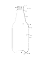
- the vertical direction means the upper side and the lower side in a state in which the synthetic resin container 1 is in the upright posture as shown in FIG. 1.
- the radially outer side is a direction toward the outer side along a straight line perpendicular to the central axis through the central axis of the synthetic resin container 1 in FIG. 1, and the radially inner side is a central axis along the straight line. It means the direction towards.
- the synthetic resin container 1 of the present embodiment is a container for containing contents containing carbon dioxide gas, and as shown in FIG. 1, the opening 2, the trunk 3, and the bottom by biaxial stretch blow molding. It is formed in the shape of a bottle with four.
- the mouth 2 is substantially cylindrical, and an external thread 2a for attaching a cap (not shown) by screw connection is integrally provided on the outer peripheral surface of the mouth 2. Further, a neck ring 2 b is integrally provided at the lower end of the mouth 2.
- the opening part 2 can also be set as the structure which changed the cap into screw connection and provided the cyclic
- the body 3 is integrally provided at the lower end of the mouth 2.
- the inside of the trunk 3 is, for example, a storage space S that can store carbonated beverages such as carbonated water as contents.
- the body 3 is integrally connected to the lower end of the mouth 2 and is integrally connected to the lower end of the neck 3a and the lower end of the neck 3a whose diameter gradually increases downward. Is formed into a shape having a shoulder portion 3b which is further greatly enlarged, and a main portion 3c which is integrally connected to the lower end of the shoulder portion 3b and extends downward with the same diameter.
- drum 3 can be variously changed, for example, setting it as the shape which does not have the neck-like part 3a.
- the bottom 4 is provided integrally with the lower end of the body 3 and closes the lower end of the body 3.
- the bottom 4 includes a ground 4 a and a bottom wall 4 b. Although the details are not illustrated, the bottom 4 is also configured in a laminated structure having the plurality of resin layers described above.
- the ground contact portion 4 a is formed in an annular shape integrally connected to the lower end of the main body portion 3 c of the trunk portion 3. Further, the ground contact portion 4a has a shape in which the diameter is gradually reduced in a curved shape downward from the connecting portion with the main body portion 3c of the trunk portion 3, and the lower end portion thereof is a ground contact surface.
- the grounding portion 4a is a portion which is grounded to the support when the synthetic resin container 1 is placed on the support such as a table in an upright posture.
- the bottom wall portion 4b is provided inside the ground contact portion 4a.
- the bottom wall portion 4b is circular, and is integrally connected to the inner peripheral edge of the grounding portion 4a at the outer peripheral edge thereof.
- the bottom wall 4 b is a flat surface perpendicular to the central axis (vertical direction) of the synthetic resin container 1.
- the bottom wall 4b is arranged to be offset to the side of the mouth 2 (upper side) with respect to the ground 4a, and forms a recess toward the inside of the container.
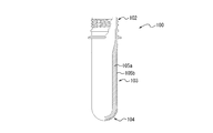
- the synthetic resin container 1 shown in FIG. 1 is formed as a container of a laminated structure having a base layer 5a and an outer layer 5b on the trunk portion 3 by biaxial stretch blow molding. That is, as described later, the synthetic resin container 1 is formed by means such as insert molding on the outside in the radial direction of the body portion 103 (base material layer 105a) of the preform 100 (see FIG. 2A) formed by injection molding.
- the outer layer 105b (see FIG. 2B) can be manufactured by biaxial stretch blow molding.
- the container 1 made of synthetic resin has a plurality of resin layers (a base material layer 5a and an outer layer 5b) in the trunk portion 3 as described above.
- the base material layer 5a is made of a resin mainly composed of polyethylene terephthalate which is a polyester resin.
- the outer layer 5b is made of a resin mainly composed of polypropylene, which is an olefin resin.
- the polypropylene constituting the outer layer 5b has a permeability coefficient to carbon dioxide gas larger than that of the polyethylene terephthalate constituting the base layer 5a.
- Each material is selected. That is, the outer layer 5b (polypropylene) is more easily permeable to carbon dioxide gas as a material than the base layer 5a (polyethylene terephthalate).
- outer layer 5b polypropylene
- base layer 5a polyethylene terephthalate
- outer layer 5b is less likely to transmit water molecules as a material than base layer 5a. It is done. Therefore, the outer layer 5b can suppress further release of even a slight amount of water molecules having passed through the base material layer 5a. Thus, water can be prevented from passing through the base layer 5a and being released to the outside without carbon dioxide gas staying between the base layer 5a and the outer layer 5b.
- the present invention is not limited to this embodiment, and other polyester resins such as PET-G resin, PCTG resin, or PCTA resin May be used.
- a resin other than polyester resin may be used as the base layer 5a, and the permeability coefficient of carbon dioxide gas of the base layer 5a may have a smaller value than the permeability coefficient of the outer layer 5b.
- a resin mainly composed of polypropylene is used as the outer layer 5b.
- another olefin resin such as polyethylene may be used.
- polyethylene low density polyethylene (LDPE), medium density polyethylene (MDPE), high density polyethylene (HDPE) or the like can be used.
- LDPE low density polyethylene
- MDPE medium density polyethylene
- HDPE high density polyethylene
- the resin having a smaller density tends to have a larger permeability coefficient to carbon dioxide gas
- resin other than an olefin resin may be used as the outer layer 5b, and the permeability coefficient of the carbon dioxide gas of the outer layer 5b should just have a larger value than the permeability coefficient of the base material layer 5a.
- FIG. 3 is a flowchart showing a method of manufacturing the synthetic resin container 1 according to the present embodiment.
- polyethylene terephthalate is injected into a cavity in an injection mold to form a preform 100 having a test tube shape shown in FIG. 2A ( Step S101).
- the preform 100 formed by the injection molding has a mouth 102, a cylindrical body 103 connected to the lower end of the mouth 102, and a bottom 104 closing the lower end of the body 103, and as a whole,
- the material layer 105a is configured.
- the opening 102 of the preform 100 has a substantially cylindrical shape, and an external thread 102 a for attaching a cap by screw connection is integrally provided on the outer peripheral surface thereof.
- a neck ring 102 b is integrally provided at the lower end of the opening 102.
- the body portion 103 of the preform 100 is integrally provided at the lower end of the mouth portion 102.
- the lower end portion of the cylindrical body portion 103 is closed by the hemispherical arc-shaped bottom portion 104, and has a test tube shape as a whole.
- the preform 100 formed in step S101 is set in an injection mold, and polypropylene as a material of the outer layer 105b is injected into the mold to perform insert molding (step S102).
- the outer layer 105b made from a polypropylene can be formed in the radial direction outer side of the base material layer 105a made from a polyethylene terephthalate in the trunk
- the outer layer 105b is formed into a preform 100 by superposing the member for the cylindrical outer layer 105b formed by injection molding different from the above-described preform 100 on the outside of the body portion 103 of the preform 100 of FIG. 2A. It may be located at Alternatively, the outer layer 105b may be disposed on the preform 100 by winding the member for the outer layer 105b formed in a sheet shape around the body portion 103 of the preform 100 of FIG. 2A.
- biaxial stretch blow molding is performed on the preform 100 with the outer layer 105b prepared in step S102 (step S103).
- the biaxial stretch blow molding is carried out by setting the preform 100 with the outer layer 105b in the mold of the stretch blow molding machine at the mouth 102 at the top of the mold.
- the outer layer 105b disposed around the body portion 103 of the preform 100 constituting the base layer 105a is thermally fused and integrally stretched to the base layer 105a due to a temperature rise during biaxial stretch blow molding,
- a container 1 made of synthetic resin, which is a biaxial stretch blow molded product shown in FIG. 1, is formed.
- the trunk portion 3 is disposed outside the base layer 5a in the radial direction of the base layer 5a and together with the outer layer 5b having one or more resin layers.
- the outer layer 5b which is formed by stretch blow molding and is adjacent to the base material layer 5a in the thickness direction and located radially outward, is configured to have a carbon dioxide gas permeation coefficient larger than that of the base material layer 5a.
- the resin layer on the radially outer side, in which the base layer 5a and the plurality of resin layers constituting the outer layer 5b are adjacent in the thickness direction has a diameter
- the permeability coefficient of carbon dioxide gas may be larger than that of the resin layer on the inner side of the direction. In this case, when the permeability coefficients of carbon dioxide gas of resin layers adjacent to each other in the thickness direction are the same, the resin layers adjacent to each other are handled as one layer in consideration of the permeability coefficient.
- At least one resin layer constituting the outer layer 5 b is configured to have a water permeation coefficient smaller than that of the base layer 5 a.
- the base material layer 5a is configured to be formed of a resin mainly composed of a polyester resin.
- the base layer 5a having a carbon dioxide gas permeation coefficient smaller than that of the outer layer 5b is formed using a relatively inexpensive material, and the carbon dioxide gas is blistered in the space between the base layer 5a and the outer layer 5b. It is possible to suppress stagnation.
- the base material layer 5a is configured to be formed of a resin mainly composed of polyethylene terephthalate.
- base material layer 5a having a carbon dioxide gas permeation coefficient smaller than that of outer layer 5b is formed using a mass-produced inexpensive material, and carbon dioxide gas is produced in the space between base material layer 5a and outer layer 5b. It is possible to suppress retention in the form of blisters.
- the outer layer 5 b is configured to include a resin mainly composed of an olefin resin.
- the outer layer 5b having a permeability coefficient of carbon dioxide gas larger than that of the base material layer 5a is formed, and the carbon dioxide gas is blistered in the space between the base material layer 5a and the outer layer 5b. It is possible to suppress stagnation.
- the outer layer 5 b may include a plurality of resin layers, and the innermost layer of the plurality of resin layers may be formed of a resin mainly composed of an olefin resin.
- the outer layer 5b is configured to have a thickness in the range of 30 ⁇ m to 100 ⁇ m. Thereby, molding defects in the case of forming the outer layer 5b by insert molding or extrusion blow molding can be suppressed.
- the body portion 103 includes the base material layer 105a and the outer layer 105b formed on the radially outer side of the base material layer 105a, and the outer layer 105b is formed of the base material layer 105a.
- the permeation coefficient of carbon dioxide gas is increased.
- the mouth 102, the cylindrical trunk 103 connected to the lower end of the mouth 102, and the lower end of the trunk 103 by injection molding Forming the preform 100 having the bottom portion 104 for closing the hole, disposing the outer layer 105b on the radially outer side of the body portion 103 of the preform 100 forming the base material layer 105a, and combining the preform 100 with the outer layer 105b
- the outer layer 5b is configured to have a permeability coefficient of carbon dioxide gas larger than that of the base material layer 5a.
- the preform 100 forming the base layer 105a and the outer layer 105b are stretched while being thermally fused, so that the base layer 5a and the outer layer 5b in the trunk portion 3 of the synthetic resin container 1 after the stretch blow molding It is possible to secure adhesion with
- a liquid containing carbon dioxide gas such as carbonated water is contained in the housing space S
- carbon dioxide gas in the liquid slightly permeates through the base layer 5a and moves between the base layer 5a and the outer layer 5b.
- the carbon dioxide gas easily passes through the outer layer 5b and is released to the outside. Therefore, carbon dioxide gas can be prevented from staying in the form of a blister in the space between the base material layer 5a and the outer layer 5b.
- the PET bottle sold as a product has a label wound on the barrel of the bottle for each product to improve the decoration of the product
- the process is to form the PET bottle and fill the contents Labels are attached to the bottle barrel in a separate process before and after.
- a label attaching process after bottle molding can be omitted.
- the step of arranging the outer layer 105 b is a step of inserting the preform 100 into a mold and performing insert molding of the outer layer 105 b.
- the outer layer 105b of the preform 100 can be formed easily and accurately.
- the step of arranging the outer layer 105 b is also a step of overlapping the cylindrical outer layer 105 b formed by, for example, injection molding, extrusion blow molding (EBM), extrusion tube molding or the like on the outside of the preform 100. Good. Thereby, the outer layer 105b of the preform 100 can be formed easily and accurately.
- EBM extrusion blow molding
- the step of arranging the outer layer 105 b may be a step of winding the sheet-like outer layer 105 b around the preform 100.
- the outer layer 105b of the preform 100 can be prepared inexpensively.
- polyethylene terephthalate (PET) and polypropylene (PP) Two-layer structure (Example 1), polypropylene (Example 2), polyethylene (Example 3), and polypropylene / polyethylene two-layer structure (Example 4) Prepared.
- the polypropylene used in this example is J246M (melt flow rate (MFR): 30), which is random polypropylene made of prime polymer.
- MFR melting flow rate
- the internal volume of the synthetic resin container 500 ml, the mass: 38 g (base layer: 30.5 g, outer layer: 7.5 g).
- the thickness of the outer layer 5b after biaxial stretch blow molding of the preform 100 constituting the base material layer 105a with the outer layer 105b formed by insert molding is 80 to 100 ⁇ m (during insert molding)
- the thickness of the outer layer 105b is about 1.5 mm).
- the outer layer 5b after biaxial stretching blow molding of the preform 100 constituting the base material layer 105a with the outer layer 105b formed by extrusion blow molding (EBM) The thickness was made to be 30 to 50 ⁇ m (corresponding to the thickness of about 0.3 to 0.4 mm of the outer layer 105 b at the time of extrusion blow molding).
- the thickness of the outer layer 5b is selected because insert molding or extrusion blow molding is favorably performed and molding defects are less likely to occur.
- the thickness of the outer layer 5b may be configured to be a thickness of 50 to 80 ⁇ m by insert molding or extrusion blow molding.
- the thickness of the outer layer 5b after biaxial stretch blow molding is made smaller than 30 ⁇ m or larger than 100 ⁇ m, molding defects may occur.
- “Configuration of outer layer” shown in Table 1 shows a resin layer formed on the left side in the radial direction and a resin layer formed on the right side in the radial direction outside.
- “Ad” indicates an adhesive layer, and for example, a modified polyolefin having adhesiveness such as “Admer (registered trademark)” can be used.
- “EVOH” is an EVOH resin layer (ethylene-vinyl alcohol copolymer resin layer), which is provided as a barrier layer.
- PP / ad / EVOH / ad / PP of Comparative Example 1 is a laminated resin laminated in the order of polypropylene / adhesive layer / EVOH resin layer / adhesive layer / polypropylene from the innermost layer toward the outermost layer.
- Table 1 The results shown in Table 1 were as follows: polyethylene terephthalate (PET) was used for the base layer, and the resin layer shown in "Configuration of outer layer” for Table 1 was used, and 4Gvol (gas volume) of carbonated water was filled in a synthetic resin container. In the state, the presence or absence of blistering when stored under an environment of 40 ° C. and 10% RH (relative humidity) and the suitability of the sorting ability are shown.
- PET polyethylene terephthalate
- 4Gvol gas volume
- the resin layer on the radially outer side is the resin layer adjacent to each other in the thickness direction.
- the permeability coefficient of carbon dioxide gas is larger than that of the resin layer on the radially inner side, the result of no blistering due to storage under an environment of 40 ° C. and 10% RH is obtained.
- the permeability coefficient of carbon dioxide gas is larger in PP, which is a resin layer adjacent to the outer side in the radial direction of PET, than that of the innermost layer of the base material layer 5a and the outer layer 5b.
- PP which is a resin layer adjacent to the outer side in the radial direction of PET
- the innermost layers of the base layer 5a and the outer layer 5b are both made of PET and have the same permeability coefficient of carbon dioxide gas
- the innermost layers of the base layer 5a and the outer layer 5b are treated as one layer.
- the adhesive layer (ad) for bonding the PET and PP of the outer layer 5b is not considered here because the thickness is small and the influence on the permeation of carbon dioxide gas is relatively small.
- Example 2 the permeability coefficient of carbon dioxide gas is larger in PP (polypropylene) which is a resin layer adjacent to the outer side in the radial direction of the base material layer 5a than in PET forming the base material layer 5a.
- PP polypropylene
- PE polyethylene
- the permeability coefficient of carbon dioxide gas may be smaller in the outer layer 5b (PE) adjacent to the outer side in the radial direction than the base material layer 5a (PET).
- each material is selected such that the permeability coefficient of carbon dioxide gas is larger in PE constituting the outer layer 5 b than in PET constituting the base material layer 5 a.
- the permeability coefficient of carbon dioxide gas is larger in PP adjacent to the radially outer side of PET and constituting the innermost layer of outer layer 5b than the PET constituting base material layer 5a, and the innermost layer of outer layer 5b
- the permeability coefficient of carbon dioxide gas is further increased in PE which is adjacent to the radially outer side of PP and which constitutes the outermost layer of the outer layer 5b than the PP which constitutes it.
- the permeability coefficient of carbon dioxide gas may be smaller in the radially adjacent PE than PP depending on the density of the selected PE, etc., in this embodiment, the PE is more suitable than PP. Each material is selected so that the permeability coefficient of carbon dioxide gas becomes larger.
- the permeability coefficient of carbon dioxide gas can be confirmed, for example, by a gas permeability test method by a differential pressure type gas chromatography method according to JIS K7126-1.
- Comparative Examples 1 to 5 include a resin layer in which the resin layer on the radially outer side has a smaller permeability coefficient of carbon dioxide gas than the resin layer on the radially inner side adjacent in the thickness direction The occurrence of blisters has been confirmed in that part.
- the permeation coefficient of carbon dioxide gas is smaller in EVOH adjacent to the radially outer side than PP constituting the innermost layer of the outer layer, and blisters occur at the boundary.
- the permeation coefficient of carbon dioxide gas is smaller in EVOH adjacent to the outer side in the radial direction than in PET forming the innermost layer of the outer layer, and blistering occurs at the boundary .
- the permeability coefficient of carbon dioxide gas is smaller in PET adjacent to the radially outer side than PP constituting the intermediate layer of the outer layer, and blisters occur at the boundary.
- the permeability coefficient of carbon dioxide gas is smaller in PET adjacent to the radially outer side than PP constituting the innermost layer of the outer layer, and blisters occur at the boundary.
- the separation ability As shown in Table 1, in Examples and Comparative Examples in which PET is used for the innermost layer of the outer layer, the PET of the base layer and the PET of the outer layer are stuck to each other, making it difficult to peel off the outer layer.
- the classification aptitude is not (x).
- the PET and the outer layer of the base layer can be easily peeled off and separated. Is good ( ⁇ ).
- Table 2 shows the weight of water in the storage space of the synthetic resin container in Example 2 having the outer layer 5b of PP in addition to the base layer 5a of PET and Comparative Example 6 having only the base layer of PET. It is the result of comparing the change rates.
- Example 2 At the storage temperature of any of 23 ° C. and 40 ° C., the direction of Example 2 in which the outer layer 5 b of PP is provided on the radially outer side of the base layer 5 a as compared with Comparative Example 6 having only the base layer of PET.
- the weight change rate of the water in the accommodation space S is suppressed to about half. This is because for PP the permeability coefficient of carbon dioxide gas is larger than that of PET, but the permeability coefficient of water is smaller for PP than PET, so by providing PP as the outer layer, it is possible for the water in the accommodation space S It is because barrier property can be improved.
Landscapes
- Engineering & Computer Science (AREA)
- Mechanical Engineering (AREA)
- Manufacturing & Machinery (AREA)
- Ceramic Engineering (AREA)
- Blow-Moulding Or Thermoforming Of Plastics Or The Like (AREA)
- Containers Having Bodies Formed In One Piece (AREA)
Abstract
L'invention concerne un récipient en résine synthétique, une préforme, et un procédé de production d'un récipient en résine synthétique dans lequel il est possible d'empêcher l'accumulation de dioxyde de carbone gazeux entre une couche de substrat et une couche externe du récipient, le récipient en résine synthétique recevant des contenus qui comprennent le dioxyde de carbone gazeux. Ce récipient en résine synthétique (1) a une partie d'ouverture (2), une partie de cylindre (3) qui est reliée à l'extrémité inférieure de la partie d'ouverture (2) et forme un espace de réception de contenus qui comprennent le dioxyde de carbone gazeux, et une partie inférieure (4) qui ferme l'extrémité inférieure de la partie de cylindre, le récipient en résine synthétique (1) étant caractérisé en ce que : la partie de cylindre (3) est formée par soufflage bi-orienté d'une couche de substrat (5a) conjointement avec une couche externe (5b) qui est disposée radialement vers l'extérieur depuis la couche de substrat (5a) et comporte une ou plusieurs couches de résine ; et les couches de résine constituant la couche de substrat (5a) et la couche externe (5b) sont telles que le coefficient de transmission de dioxyde de carbone gazeux dans une couche de résine radialement vers l'extérieur qui est adjacente dans une direction d'épaisseur est supérieur à celui dans une couche de résine radialement vers l'intérieur.
Applications Claiming Priority (2)
| Application Number | Priority Date | Filing Date | Title |
|---|---|---|---|
| JP2017231190A JP7242174B2 (ja) | 2017-11-30 | 2017-11-30 | 合成樹脂製容器、プリフォーム、及び合成樹脂製容器の製造方法 |
| JP2017-231190 | 2017-11-30 |
Publications (1)
| Publication Number | Publication Date |
|---|---|
| WO2019106905A1 true WO2019106905A1 (fr) | 2019-06-06 |
Family
ID=66665500
Family Applications (1)
| Application Number | Title | Priority Date | Filing Date |
|---|---|---|---|
| PCT/JP2018/032873 Ceased WO2019106905A1 (fr) | 2017-11-30 | 2018-09-05 | Récipient en résine synthétique, préforme et procédé de production de récipient en résine synthétique |
Country Status (2)
| Country | Link |
|---|---|
| JP (1) | JP7242174B2 (fr) |
| WO (1) | WO2019106905A1 (fr) |
Cited By (1)
| Publication number | Priority date | Publication date | Assignee | Title |
|---|---|---|---|---|
| CN114787043A (zh) * | 2019-12-06 | 2022-07-22 | 株式会社细川洋行 | 排出用部件、收纳容器、排出用部件的制造方法、注射成型用模具以及带封闭部件的排出用部件 |
Families Citing this family (1)
| Publication number | Priority date | Publication date | Assignee | Title |
|---|---|---|---|---|
| JP6877506B2 (ja) * | 2019-09-13 | 2021-05-26 | スケーター株式会社 | プラスチック製容器の製造方法及び装置 |
Citations (1)
| Publication number | Priority date | Publication date | Assignee | Title |
|---|---|---|---|---|
| JP2017036069A (ja) * | 2015-08-10 | 2017-02-16 | 大日本印刷株式会社 | 複合容器、複合プリフォーム、複合容器の製造方法、およびプラスチック製部材 |
Family Cites Families (2)
| Publication number | Priority date | Publication date | Assignee | Title |
|---|---|---|---|---|
| JP3733974B2 (ja) * | 1995-11-09 | 2006-01-11 | 株式会社クレハ | 食品包装用積層フイルム |
| JP2005225136A (ja) * | 2004-02-13 | 2005-08-25 | Kureha Chem Ind Co Ltd | 炭酸ガス選択透過性を有する積層フィルム |
-
2017
- 2017-11-30 JP JP2017231190A patent/JP7242174B2/ja active Active
-
2018
- 2018-09-05 WO PCT/JP2018/032873 patent/WO2019106905A1/fr not_active Ceased
Patent Citations (1)
| Publication number | Priority date | Publication date | Assignee | Title |
|---|---|---|---|---|
| JP2017036069A (ja) * | 2015-08-10 | 2017-02-16 | 大日本印刷株式会社 | 複合容器、複合プリフォーム、複合容器の製造方法、およびプラスチック製部材 |
Cited By (2)
| Publication number | Priority date | Publication date | Assignee | Title |
|---|---|---|---|---|
| CN114787043A (zh) * | 2019-12-06 | 2022-07-22 | 株式会社细川洋行 | 排出用部件、收纳容器、排出用部件的制造方法、注射成型用模具以及带封闭部件的排出用部件 |
| US12441530B2 (en) | 2019-12-06 | 2025-10-14 | Hosokawa Yoko Co., Ltd. | Discharge member, accommodating container, method for manufacturing discharge member, mold for injection molding, and discharge member with closing member |
Also Published As
| Publication number | Publication date |
|---|---|
| JP2019099207A (ja) | 2019-06-24 |
| JP7242174B2 (ja) | 2023-03-20 |
Similar Documents
| Publication | Publication Date | Title |
|---|---|---|
| EP3257652B1 (fr) | Récipient moulé par soufflage étiré biaxialement | |
| EP3015245B1 (fr) | Procédé de moulage par soufflage, préforme composite, récipient composite, élément étiquette intérieure et élément constitué de plastique | |
| US11975885B2 (en) | Delamination container | |
| JP6867111B2 (ja) | 二重構造容器成形用プリフォーム及び二重構造容器 | |
| US10569461B2 (en) | Preform for biaxial stretching blow molding, and container | |
| JP2015009493A (ja) | ブロー成形方法および複合プリフォーム | |
| CN107848185B (zh) | 阻挡管肩 | |
| JP7039306B2 (ja) | 積層剥離容器 | |
| WO2019106905A1 (fr) | Récipient en résine synthétique, préforme et procédé de production de récipient en résine synthétique | |
| JP2017148963A (ja) | ブロー成形プラスチックボトルの製造方法、ブロー成形プラスチックボトル、ブロー成形プラスチックボトル用金型、および表面部材 | |
| JP2002068229A (ja) | 積層ボトルの口上面シール構造 | |
| JP6625314B2 (ja) | ブロー成形方法および複合容器 | |
| JP2018197114A (ja) | ボトルと支持容器との組合体および支持容器の製造方法 | |
| JP6842651B2 (ja) | プラスチック容器および内容物入り容器 | |
| JP7015474B2 (ja) | プラスチックボトル | |
| JP7508858B2 (ja) | 二重容器、二重容器の製造方法及び二重プリフォーム | |
| US20080057243A1 (en) | Container | |
| JP7322492B2 (ja) | 容器及びそのプリフォーム | |
| JP2021014128A (ja) | 複合プリフォーム | |
| JP2015009487A (ja) | ブロー成形方法および複合プリフォーム | |
| JP6835188B2 (ja) | 複合容器の製造方法および製造システム | |
| JP2023176747A (ja) | 積層容器 | |
| JP6458472B2 (ja) | ブロー成形方法、複合プリフォーム、複合容器、内側ラベル部材およびプラスチック製部材 | |
| JP5108495B2 (ja) | 合成樹脂製容器 | |
| JP4587179B2 (ja) | 合成樹脂製多層容器 |
Legal Events
| Date | Code | Title | Description |
|---|---|---|---|
| 121 | Ep: the epo has been informed by wipo that ep was designated in this application |
Ref document number: 18884361 Country of ref document: EP Kind code of ref document: A1 |
|
| NENP | Non-entry into the national phase |
Ref country code: DE |
|
| 122 | Ep: pct application non-entry in european phase |
Ref document number: 18884361 Country of ref document: EP Kind code of ref document: A1 |