WO2019106934A1 - Outil électrique - Google Patents
Outil électrique Download PDFInfo
- Publication number
- WO2019106934A1 WO2019106934A1 PCT/JP2018/036310 JP2018036310W WO2019106934A1 WO 2019106934 A1 WO2019106934 A1 WO 2019106934A1 JP 2018036310 W JP2018036310 W JP 2018036310W WO 2019106934 A1 WO2019106934 A1 WO 2019106934A1
- Authority
- WO
- WIPO (PCT)
- Prior art keywords
- rotor core
- motor
- coil
- shaft
- housing
- Prior art date
- Legal status (The legal status is an assumption and is not a legal conclusion. Google has not performed a legal analysis and makes no representation as to the accuracy of the status listed.)
- Ceased
Links
Images





Classifications
-
- B—PERFORMING OPERATIONS; TRANSPORTING
- B24—GRINDING; POLISHING
- B24B—MACHINES, DEVICES, OR PROCESSES FOR GRINDING OR POLISHING; DRESSING OR CONDITIONING OF ABRADING SURFACES; FEEDING OF GRINDING, POLISHING, OR LAPPING AGENTS
- B24B23/00—Portable grinding machines, e.g. hand-guided; Accessories therefor
- B24B23/02—Portable grinding machines, e.g. hand-guided; Accessories therefor with rotating grinding tools; Accessories therefor
-
- B—PERFORMING OPERATIONS; TRANSPORTING
- B24—GRINDING; POLISHING
- B24B—MACHINES, DEVICES, OR PROCESSES FOR GRINDING OR POLISHING; DRESSING OR CONDITIONING OF ABRADING SURFACES; FEEDING OF GRINDING, POLISHING, OR LAPPING AGENTS
- B24B47/00—Drives or gearings; Equipment therefor
- B24B47/10—Drives or gearings; Equipment therefor for rotating or reciprocating working-spindles carrying grinding wheels or workpieces
- B24B47/12—Drives or gearings; Equipment therefor for rotating or reciprocating working-spindles carrying grinding wheels or workpieces by mechanical gearing or electric power
-
- B—PERFORMING OPERATIONS; TRANSPORTING
- B25—HAND TOOLS; PORTABLE POWER-DRIVEN TOOLS; MANIPULATORS
- B25F—COMBINATION OR MULTI-PURPOSE TOOLS NOT OTHERWISE PROVIDED FOR; DETAILS OR COMPONENTS OF PORTABLE POWER-DRIVEN TOOLS NOT PARTICULARLY RELATED TO THE OPERATIONS PERFORMED AND NOT OTHERWISE PROVIDED FOR
- B25F5/00—Details or components of portable power-driven tools not particularly related to the operations performed and not otherwise provided for
-
- H—ELECTRICITY
- H02—GENERATION; CONVERSION OR DISTRIBUTION OF ELECTRIC POWER
- H02K—DYNAMO-ELECTRIC MACHINES
- H02K1/00—Details of the magnetic circuit
- H02K1/06—Details of the magnetic circuit characterised by the shape, form or construction
- H02K1/22—Rotating parts of the magnetic circuit
- H02K1/27—Rotor cores with permanent magnets
-
- H—ELECTRICITY
- H02—GENERATION; CONVERSION OR DISTRIBUTION OF ELECTRIC POWER
- H02K—DYNAMO-ELECTRIC MACHINES
- H02K7/00—Arrangements for handling mechanical energy structurally associated with dynamo-electric machines, e.g. structural association with mechanical driving motors or auxiliary dynamo-electric machines
- H02K7/04—Balancing means
-
- H—ELECTRICITY
- H02—GENERATION; CONVERSION OR DISTRIBUTION OF ELECTRIC POWER
- H02K—DYNAMO-ELECTRIC MACHINES
- H02K9/00—Arrangements for cooling or ventilating
- H02K9/02—Arrangements for cooling or ventilating by ambient air flowing through the machine
- H02K9/04—Arrangements for cooling or ventilating by ambient air flowing through the machine having means for generating a flow of cooling medium
- H02K9/06—Arrangements for cooling or ventilating by ambient air flowing through the machine having means for generating a flow of cooling medium with fans or impellers driven by the machine shaft
Definitions
- the present invention relates to a power tool that holds a motor inside a motor housing, and more particularly to an improvement in the assembly structure of a rotor core.
- a handle connected so as to project rearward from the motor housing holding the motor is provided, and the operator holds the handle with one hand and the motor with the other hand Work while holding the housing itself or the side handle on which the motor housing is mounted.
- the housing of the disc grinder has a metal or synthetic resin housing
- the motor housing is not shaped so as to be divided in a plane passing through the axis because the size and output of the motor are large in medium to large disc grinders. It has a cylindrical integral shape, and the left and right split handle housing is attached to the rear side. The motor is inserted into the motor housing axially rearward from an opening on the front side (opposite to the handle housing) of the cylindrical motor housing.
- Patent Document 1 is known as a grinder having such a motor attachment structure.
- the motor housing is integrally molded of synthetic resin, and the rotary shaft of the motor is supported by a bearing fixed by the motor housing and a bearing fixed by a member covering the front opening of the motor housing.
- the brushless DC motor is driven using an inverter circuit using a semiconductor switching element.
- a semiconductor switching element used for the inverter circuit an FET (field effect transistor), an IGBT (insulated gate bipolar transistor) or the like is used.
- the brushless DC motor is provided with a rotor having a permanent magnet inside and a stator having a coil wound on the outside.
- the cooling fan is provided on the front side of the motor as viewed in the axial direction of the rotation shaft of the motor, and when the motor 5 rotates, the cooling fan rotates in conjunction with the rotation shaft. Generates a flow of wind to the side (cooling air).
- the control circuit and motor are cooled by the cooling air.
- the cooling air having flowed into the housing space of the motor passes axially through the gap between the outer peripheral side of the stator and the motor housing and the gap between the stator and the rotor from the rear in the axial direction Flow through the through hole of the fan cover and is discharged to the outside from the through hole of the gear case. Since a strong magnet such as neodymium is usually used for the rotor of a brushless DC motor, dust (metal powder) generated at the time of work is used as a cooling air when grinding work with iron or the like using a grinder. And there was a risk of getting into the product body.
- an axially continuous V-shaped groove is formed in the outer peripheral portion of the rotor core, the air path of the cooling air is enlarged by the V-shaped groove, and the dust flowing inside is discharged to the outside of the housing.
- the structure is easy to
- a balance weight having the same diameter as the outer diameter of the stator core is disposed as a balance weight disposed adjacent to the rotor core.
- the balance weight is a wall that closes the end of the V-shaped groove, making it difficult for dust to be discharged from the V-shaped groove and causing a problem that dust tends to be accumulated in the V-shaped groove.
- the present invention has been made in view of the above background, and an object thereof is dust such as iron powder at an end of a stator core when attaching a balance weight to an end of a stator core having a groove continuously in the axial direction in an outer peripheral surface. It is an object of the present invention to provide a power tool which can prevent the adhesion of Another object of the present invention is to mount the sensor substrate radially outward on the balance weight by using a cylindrical balance weight having a circular cross-sectional shape and a small diameter on the stator core having a non-circular cross-sectional shape orthogonal to the axial direction And to provide a power tool. Still another object of the present invention is to provide an electric power tool in which iron powder and the like are less likely to adhere to the end face of the stator core by covering the entire end face of the stator core with a resin member.
- a motor having a rotor core mounted on the rotary shaft and containing a permanent magnet and a stator core located on the outer periphery of the rotor core, a cylindrical housing for housing the motor, and a rotary shaft mounted
- An electric power tool having a cooling fan to take in outside air by means of the fan and flowing cooling air around the motor in the housing in the direction of the rotational axis, which is cylindrical and is larger than the outer diameter of the rotor core
- a small nonmagnetic metal balancer member is provided on one side or both sides in the axial direction of the rotor core, and a resin spacer member is interposed between the balancer member and the rotor core.
- a plurality of axial grooves are formed continuously on the outer peripheral surface of the rotor core from one axial end face to the other axial end face of the rotor core, and the spacer member has a shape similar to the outer edge shape of the rotor core end face The outer edge of the
- the spacer member is a substantially annular member having a through hole formed in the center, and the balancer member has a circular cross-sectional shape of the outer edge before making a radial hole for balance adjustment.
- the spacer member and the balancer member are fixed to the rotation shaft by press-fitting the through holes of the spacer member and the balancer member to the rotation shaft in a state in which the rotor core is fixed.
- Ru a coil for passing an exciting current is wound around the stator core
- a shaft made of synthetic resin is molded on the outer surface of the rotary shaft to ensure insulation between the outer surface of the rotary shaft and the stator core, and the spacer member is It is formed by molding according to the time of shaft mold processing.
- the cross-sectional shape of the outer edge before making a radial adjustment hole for balance adjustment is a perfect circle, a through hole extending in the axial direction is formed at the center, and it is pressed into the rotating shaft after the shaft molding is completed.
- the rotor core is formed of a laminated core having a through hole at the center and a slot for accommodating a plate-like permanent magnet radially outward of the through hole.
- the outer diameter of the balancer member is formed with a diameter smaller than the position of the outer surface of the permanent magnet in the normal direction of the permanent magnet passing through the rotation axis.
- a hole for adjusting the rotational balance of the rotor is provided on the outer peripheral surface of the balancer member, and the thickness in the rotational axis direction of the spacer member is thinner than the thickness in the rotational axis direction of the balancer member.
- a motor having a rotor core mounted on a rotary shaft and using a permanent magnet and a stator core positioned on the outer periphery of the rotor core, a cylindrical housing for housing the motor, and a rotary shaft
- An electric power tool having a cooling fan for taking in outside air by the fan and flowing cooling air around the motor in the housing in the direction of the rotational axis, the outer peripheral surface of the rotational shaft and the inner peripheral surface of the rotor core
- the shaft molding process is performed between the two, and the rotational shaft and the both end surfaces of the stator core are integrally molded by expanding the mold portion to a portion covering the both end surfaces of the stator core.
- a balancer member which is cylindrical and smaller than the outer diameter of the rotor core is provided at the leeward end of the rotor core.
- a spacer having the same shape as the V-shaped cross-sectional shape is disposed between the balance weight and the rotor core, and a balance weight having a diameter smaller than the V-groove bottom of the rotor core is disposed. It becomes possible to pass dust efficiently. In addition, metal dust of the brushless motor can be prevented from adhering to the rotor core, and the occurrence of motor lock can be suppressed.
- FIG. 6 is an exploded perspective view showing a mounting state of an inverter circuit section 20 mounted on the rear side of the motor housing 10 of FIG. 1. It is a perspective view which shows the stator 30 of the motor 5 of FIG. 1 (state before winding of a coil). It is a figure which shows the stator 30 of FIG. 4, Comprising: (1) is a side view, (2) is a rear view. It is a figure for demonstrating how to wind the stator coil in a prior art example.
- FIG. (1) is a side view of the rotor 70 and the cooling fan 13 of the motor 5, (2) is a cross-sectional view of the DD portion of (1) (a side view of the rotor core 71).
- (1) is a cross-sectional view taken along the line AA in FIG. 1
- (2) is a cross-sectional view taken along the line BB in FIG.
- FIG. 1 is a cross-sectional view showing the overall configuration of a disk grinder 1 according to an embodiment of the present invention.
- the disc grinder 1 operates a body 2 in which a motor 5 serving as a driving source is accommodated inside a cylindrical motor housing 10, and a working device driven by the motor 5 (here, a grinder using a grinding stone 98 as a tip tool) And a handle portion 4 provided on the rear side of the body portion 2 and gripped by an operator.
- the handle portion 4 is configured to be rotatable (slidable) by a predetermined angle around the rotation axis A1 of the motor 5 by being connected to the body portion 2 via a rotation mechanism.
- a brushless motor 5 is accommodated in the motor housing 10.
- the motor 5 includes a stator 30 having a rotor 70 having permanent magnets disposed on the inner circumferential side and a coil on the outer circumferential side.
- the rotating shaft 60 of the motor 5 is rotatably held by a bearing 15b provided near the central portion of the motor housing 10 and a bearing 15a on the front side held by the gear case 6 covering the front opening of the motor housing 10.
- the power transmission unit 3 includes a disk-shaped grindstone 98 attached to a spindle 8 supported by bearings 9 a and 9 b in a gear case 6 and a wheel guard 29.
- a pair of bevel gears 7 a and 7 b are disposed, and the rotational force of the rotation shaft 60 of the motor 5 is changed in direction and transmitted to the spindle 8.
- a tip end tool holding portion is formed by the press fitting 14 b via the receiving fitting 14 a, and the grindstone 98 is fixed.
- a side handle attachment hole 6b is provided at the top of the gear case 6, and similar side handle attachment holes (not shown) are provided on the right and left sides of the gear case 6 as well.
- the inverter circuit portion 20 is inserted from the rear end side opening of the motor housing 10, and thereafter, the opening portion is covered by the support member 133 and the intermediate member 125.
- the support member 133 is configured to be divisible in the left-right direction, and sandwiches the swing support shaft of the intermediate member 125 between the left and right divided pieces.
- Two radially projecting flange portions 126 are formed on the outer peripheral surface of the intermediate member 125, and the handle housing 16 forming the grip portion is rotatably held along the flange portions.
- the circuit board 27 of the inverter circuit unit 20 is a substantially annular multi-layered board having a diameter slightly larger than the outer shape of the motor 5, and the surface thereof is disposed in the direction orthogonal to the rotation axis A 1 of the motor 5.
- Six switching elements (described later) such as six insulated gate bipolar transistors (IGBTs) are mounted on the circuit board 27.
- the circuit board 27 on which the switching element is mounted is fixed inside the container-like cylindrical case 21.
- the inner diameter of the motor housing 10 in the portion accommodating the inverter circuit portion 20 is formed to be slightly larger than that in the portion accommodating the motor 5.
- a small annular ring shaped sensor substrate 122 is mounted between the bearing 15b and the stator 30 as viewed in the direction of the rotation axis A1.
- the sensor substrate 122 has an annular substrate portion, and on the side facing the stator 30, three Hall ICs 121 (described later in FIG. 2) for directly detecting the magnetic field generated by the rotor 70 are mounted at intervals of 60 degrees
- a cooling fan 13 is provided on the front side of the motor 5 and between the bearing 15a.
- the cooling fan 13 is a centrifugal fan and sucks the air on the motor 5 side and discharges it radially outward.
- a fan guide 12 is formed around the rotating shaft 60 to form a through hole of a predetermined size to form an inlet of the cooling fan.
- the air taken up from the air hole (not shown) of the handle housing 16 is drawn into the motor housing 10 by the air flow generated by the cooling fan 13 and the air flow (air flow) from the rear side to the front side of the motor 5 is obtained.
- outside air is taken in from the slit-like air intake hole (not shown) formed in the handle housing 16, and a through hole or a wind window (not shown in FIG. 1) formed in the intermediate member 125 and the support member 133. And flows into the internal space of the motor housing 10 from the rear side opening of the motor housing 10.
- the air that has flowed in first cools the electronic components mounted in the inverter circuit unit 20, passes through the side notches of the inverter circuit unit 20, and is on the outer peripheral side of the cylindrical case 21 of the inverter circuit unit 20, It reaches near the bearing holder 109 through the gap with the motor housing 10.
- a plurality of air windows are formed on the outer peripheral side of the bearing holder 109, and the air flow passing through the air windows reaches the motor 5 side.
- the air flow reaching the motor 5 side flows so as to pass between the rotor 70 and the stator 30 and between the stator 30 and the inner wall portion of the motor housing 10, and is drawn from near the axial center of the cooling fan 13
- the air flows radially outward of the cooling fan 13 and passes through an air hole formed on the outer peripheral side of the bearing holder 11.
- a part of the cooling air discharged from the bearing holder 11 is discharged to the outside as indicated by an arrow 79 a through an exhaust port (not shown) formed in the gear case 6, and the remaining is near the lower side of the bearing holder 11.
- the air is exhausted to the outside as indicated by an arrow 79 b through an exhaust port (not shown).
- the motor housing 10 is integrally formed in a cylindrical shape, so that the motor 5 can be supported more firmly than supported by the motor housing divided by the cross section including the rotation axis A1, Sufficient rigidity was secured.
- the handle portion 4 is a portion gripped by the operator at the time of operation, and its housing is composed of a handle housing 16 configured by left and right division by plastic molding and fixed by four screws (not shown). Ru.
- the handle portion 4 can be rotated 90 degrees to one side and 90 degrees to the other side from the state of FIG. 1 around the rotation axis A1, and the handle portion 4 can be fixed to the motor housing 10 in the rotated state.
- the rotation mechanism includes a flange portion 126 formed in a rib shape formed on the outer peripheral edge on the rear side of the intermediate member 125, and a rotation groove 125a formed in the handle housing 16. This is realized by fitting together.
- the control circuit unit 19 is accommodated behind the intermediate member 125.
- the control circuit portion 19 is held by the handle housing 16 so as to extend in a direction orthogonal to the rotation axis A1.
- the control circuit unit 19 accommodates a control circuit board (not shown) as a second circuit board in a shallow case, and a control circuit (described later) of the motor 5 is mounted.
- a power cord 99 for supplying commercial AC power is connected to the rear end side of the handle portion 4.
- a trigger switch 18 for controlling on / off of the motor 5 is disposed at a central portion of the handle housing 16. The trigger switch 18 is switched on or off by operating the trigger lever 17.
- the motor 5 Before mounting the power transmission unit 3, the motor 5 is inserted from the front side of the motor housing 10 toward the rear side in the direction of the rotation axis A 1, and inserts the motor 5 to a predetermined position abutting the motor housing 10. Then, the synthetic resin insulator 40 (described later in FIG. 4) located at the rear end of the stator 30 abuts on the bearing holder 109 of the motor housing 10.
- the bearing 15 b for supporting the rear end portion of the rotating shaft 60 is a ball bearing, and the outer ring side thereof is held by the bearing holder 109.
- the bearing holder 109 is manufactured integrally with the motor housing 10, and a plurality of ribs are formed in a grid shape between the inner wall of the motor housing 10 and the bearing holder 109 in order to support the bearing holder 109.
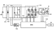
- a commercial AC power supply 100 is externally supplied by a power supply cord 99 and rectified to direct current.
- the bridge diode 112 full-wave rectifies the alternating current input from the commercial alternating current power supply 100 and outputs it to the smoothing circuit 113.
- the smoothing circuit 113 smoothes the pulse current contained in the current rectified by the bridge diode 112 to a state close to direct current and outputs the smoothed current to the inverter circuit 118.
- the smoothing circuit 113 includes an electrolytic capacitor 114, a capacitor 115, and a discharge resistor 116.
- the inverter circuit 118 includes six switching elements Q1 to Q6, and the switching operation is controlled by the gate signals H1 to H6 supplied from the operation unit 110.
- the switching elements Q1 to Q6 use insulated gate bipolar transistors (IGBTs), but field effect transistors (FETs) may be used.
- IGBTs insulated gate bipolar transistors
- FETs field effect transistors
- the output of the inverter circuit 118 is connected to the U-phase, V-phase, and W-phase of the coil of the motor 5.
- the low voltage power supply circuit 119 is connected to the output side of the bridge diode 112.
- the low voltage power supply circuit 119 is a known power supply circuit that supplies direct current of a stable reference voltage (low voltage) for the operation unit 110 to operate.
- a rotor 70 having permanent magnets rotates inside the stator 30 of the motor 5, a rotor 70 having permanent magnets rotates. In the vicinity of the rotor 70, rotational position detection elements by three Hall ICs 121 are provided, and the calculation unit 110 detects the rotational position of the rotor 70 by monitoring the output of the rotor 70.
- a sensor substrate 122 (see FIG. 1) on which the Hall IC 121 is mounted is disposed at a position facing one end surface of the rotor 70.
- the calculation unit 110 is a control unit for performing on / off control and rotation control of the motor 5, and is mainly configured using a microcomputer (not shown) (hereinafter, referred to as "microcomputer").
- the arithmetic unit 110 is mounted on the circuit board of the control circuit unit 19 (see FIG. 1), and rotates the motor 5 based on the start signal input along with the operation of the trigger switch 18 to the coils U, V, W. Control the energizing time and drive voltage.
- a speed change dial may be provided to set the rotational speed of the motor 5, and the calculation unit 110 may adjust the speed of the motor 5 to match the speed set by the speed change dial.
- the output of operation unit 110 is connected to each gate of six switching elements Q1 to Q6 of inverter circuit 118.
- the emitters or the collectors of the six switching elements Q1 to Q6 of the inverter circuit 118 are connected to the U phase, the V phase, and the W phase of the delta-connected coil.
- Switching elements Q1 to Q6 perform switching operation based on gate signals H1 to H6 input from operation unit 110, and direct current voltage supplied from commercial AC power supply 100 via rectification circuit 111 is divided into three phases (U phase, It supplies to each phase of the motor 5 as V phase, W phase) voltage Vu, Vv, and Vw.
- the magnitude of the current supplied to the motor 5 is detected by the operation unit 110 by detecting the voltage value across the shunt resistor 117 connected between the smoothing circuit 113 and the inverter circuit 118.
- the motor housing 10 is manufactured by integral molding of synthetic resin, and a fan housing portion 101 having a large outer diameter is formed on the front side of the motor housing portion 102 for housing the motor 5.
- the outer diameter is formed large, and in order to fix the gear case 6 (see FIG. 1) at four places on the outer periphery with screws.
- the screw bosses 105a to 105d are formed.
- a large diameter circuit board accommodating portion 104 for accommodating the inverter circuit portion 20 is formed in the vicinity of the rear opening of the motor housing 10.
- the diameter of the circuit board accommodating portion 104 is formed to be larger than the diameter of the motor accommodating portion 102. Therefore, a connection portion from the motor housing portion 102 to the circuit board housing portion 104 is a tapered portion 103 which spreads in a tapered manner.
- a bearing holder 109 (both shown in FIG. 1) which is a portion for holding the bearing 15b is formed.
- a recess (described later in FIG. 11) is formed to prevent the stator 30 from rotating around the rotational axis A1.
- the stator 30 by supporting the stator 30 with the motor housing 10 formed as an integral cylindrical mold, the stator 30 can be held more firmly than in the case of the left and right two-split motor housing. It is possible to cope with high output of In particular, since the stator 30 is formed of a laminated core and the specific gravity is large and the total weight is heavy, integrally forming the motor housing 10 is preferable in terms of strength.
- the inverter circuit unit 20 is formed of an IGBT circuit element group 26 in which electronic components are mounted on a circuit board 27 and a container-like cylindrical case 21 for housing them.
- the cylindrical case 21 is one in which one side (front side) of the substantially cylindrical outer peripheral surface 24 is closed by the bottom surface 23, and the IGBT circuit element group 26 is accommodated in the inner space thereof.
- the switching element group for driving the motor in the cylindrical case 21 as described above, the switching element can be mounted on a portion close to the motor 5 and the wiring from the circuit board 27 to the motor 5 can be shortened.
- the cylindrical case 21 is disposed such that the opening side is the handle portion 4 side (backward direction), that is, the air intake side, and the bottom surface 23, which is a closed surface, is disposed to be the motor 5 side (forward).
- the support member 133 is a member that closes the rear opening of the motor housing 10. Through holes 134a and 134b are formed in the vicinity of the central axis of the support member 133, and a cone-shaped swing support member (not shown) constituting the front end of the handle portion 4 is sandwiched and connected.
- the support member 133 uses the four screw holes 137a to 137d (in FIG. 3, the screw holes 137a and 137c can not be seen) in a state where the right side portion 133a and the left side portion 133b are joined. It is fixed to the opening.
- the rear opening of the motor housing 10 is formed with screw bosses 106a to 106d formed with holes for passing screws. Further, in the vicinity of the screw bosses 106a to 106d, axially extending ribs 107a and 107b for holding the outer peripheral surface of the cylindrical case 21 and a rail portion 108 are formed.
- Semi-cylindrical pressing members 136a to 136d extending to the front side are formed on the outer peripheral portion of the support member 133 and through which the screws pass. The pressing members 136a to 136d abut on the cylindrical outer peripheral surfaces of the screw bosses 106a to 106d on the motor housing 10 side, and hold a part of the rear side opening edge of the cylindrical case 21.
- a plurality of wind windows 135a and 135b for flowing the wind in the axial direction are formed by the mesh structure on the radially outer side of the through holes 134a and 134b.
- the outer peripheral shape of the cylindrical case 21 is formed with an axially continuous recess along the inner shape of the circuit board accommodating portion 104 of the motor housing 10.
- the locking holding portions 25a to 25d are recessed portions to avoid the cylindrical screw bosses 106a to 106d of the motor housing 10.
- the stepped portions 24a and the notched portions 24b on the left and right sides of the cylindrical case 21 act as an air passage which flows from the axial rear side of the support member 133 to the motor 5 side.
- the main electronic components mounted on the circuit board 27 are six semiconductor switching elements Q1 to Q6 (Q4 and Q5 are not visible in the figure).
- An independent metal heat sink is attached to the switching elements Q1 to Q3 and arranged so that the plane direction extends in the left and right and front and back directions, that is, parallel to the inflow direction of the cooling air.
- Above the switching elements Q1 to Q3, three switching elements Q4 to Q6 (in the figure, Q4 and Q5 can not be seen) are arranged so that the surface direction extends in the left and right and front and back directions. Since the emitter terminals of these switching elements Q4 to Q6 are grounded in common, a common metal heat dissipation plate which is long in the lateral direction is provided.
- the switching elements Q1, Q2, Q3, and Q4 to Q6 are shielded by a partition plate 28 made of a nonconductive member.
- a bridge diode 112 is provided on the top of the circuit board 27. In the lower part of the bridge diode 112, two capacitors 114, 115 are mounted.
- the circuit board 27 has a terminal for soldering a power line connected from the trigger switch 18 and a terminal for soldering a power line for transmitting drive power of U phase, V phase and W phase to the motor 5 (see FIG.
- a connector terminal (not shown) of a wire harness for connection with the control circuit section 19 is provided.
- Power lines connected to the motor 5 are connected to the lead wires 54a to 54c (see FIG. 1) of the stator 30 (see FIG. 1) via a space formed between the step 24a on the outer periphery of the cylindrical case 21 and the inner wall surface of the motor housing 10. 7) to be connected.
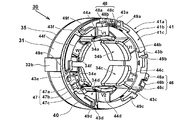
- FIG. 4 is a perspective view showing the stator 30 of the motor 5 and shows a state before winding of the coil.
- two insulators 35, 40 are provided on the front side and the rear side in the axial direction so as to surround the teeth 34a to 34f of the stator core 31 between the first insulator 35 and the second insulator 40.
- Six coils are wound.
- the insulators 35 and 40 are formed of non-conductive members such as synthetic resin.
- a cylindrical portion is formed on the outer peripheral side of the insulator 40, and six wound portions 44a to 44f are provided so as to protrude toward the inner side, and along the outer peripheral side of the wound portions 44a to 44f A coil is wound.
- the annular portion 41 of the insulator 40 is formed with a cylindrical outer peripheral surface 41 a and an annular end surface 41 c which is an annular flat surface orthogonal to the rotation axis A 1.
- the shapes of the outer peripheral surface 41a and the annular end surface 41c will be described later with reference to FIG.
- the projection shape of the insulator 40 viewed from the axial direction of the rotation axis A1 is the same as the projection shape of the stator 30. Therefore, the insulator 40 is formed with a plurality of wound portions 44a to 44f extending from the annular portion 41 to the inner peripheral side, and the innermost peripheral side of the wound portions 44a to 44f extends in the circumferential direction and the axial direction Thus, stoppers 45a to 45f (refer to FIG.
- the coil (not shown) of the motor 5 winds a copper nichrome wire a plurality of times so as to extend over the winding portion of the front insulator 35 and the winding portions 44a to 44f of the rear insulator 40.
- Six sets of coils formed by winding are wired in a delta connection.
- the annular portion 41 of the insulator 40 is formed with three lead portions 46 to 48 that project in the axial direction.
- the lead portions 46 to 48 serve to guide the winding of the delta-connected coil and, since they are intermediate points of the delta connection, serve as connection points for holding and connecting the lead wires for driving power supply.
- the lead-out portions 46 to 48 are terminal attachment grooves for mounting the axial direction convex portions 46a, 47a, 48a, the depressed portions 46b, 47b, 48b, and the metal terminals 59a, 59b, 59c (described in detail in FIG. 9). 46c, 47c, 48c are formed.
- Radially continuous radial grooves 43a to 43f are formed in the vicinity of the wound portions 44a to 44f of the insulator 40, ie, on the annular end face 41c on one side in the rotational direction from the wound portions 44a to 44f.
- the radial grooves 43a to 43f are slot portions for wiring two lead wires (different phase crossover wires 56a to 56c) radially outward from the wound coil, and are in the axial direction with respect to the annular end surface 41c. It has a shape that is cut out on the front side.
- Wall portions 49a to 49f substantially L-shaped when viewed from the rotational axis direction are formed on one circumferential side (side away from the wound portions 44a to 44f) of the radial grooves 43a to 43f Be done.
- the wall portions 49a to 49f are formed to stably hold lead wires from the coil (different phase crossovers 56a to 56c), and have wall surfaces extending in the radial direction along the radial grooves 43a to 43f, and an annular end face It has a wall surface extending a predetermined distance in the circumferential direction along the inner peripheral surface of 41c, and has a substantially L-shaped shape in the axial direction.
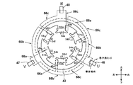
- FIG. 5 (1) is a side view of the stator 30, and (2) is a rear view.
- keys 32a and 32b which project radially outward and are axially continuous projections are formed.
- the outer shape of the stator core 31 is circular except for the keys 32a and 32b, and the outer shapes of the insulators 35 and 40 disposed in front of and behind the key 32a and 32b are circular.
- the outer diameters of the insulators 35 and 40 appear to be slightly smaller than the outer diameter of the stator core 31, but the difference is that the stator 30 is inserted in the axial direction of the cylindrical motor housing 10.
- stator core 31 stably contacts the inner wall portion of the motor housing 10 because the outer diameter of the stator core 31 is slightly larger than that of the insulators 35 and 40.
- a circumferential groove 42 which is a concave portion which is recessed in the radial direction and which is continuously formed in the circumferential direction is formed. Further, radial grooves 43a to 43f are formed such that the outer peripheral surface is cut away in the direction of the rotation axis A1 so as to cross the circumferential groove 42. The radial grooves 43a to 43f are formed only on one side of the wound portions 44a to 44f of the insulator 40 as viewed from the rear side in the direction of the rotation axis A1.
- the W-phase lead-out portion 48 is formed on the radially outer side of the wound portion 44a, and the U-phase drawn portion 46 is formed on the radially outer side of the wound portion 44c.
- a V-phase lead-out portion 47 is formed on the radially outer side of 44e.
- FIG. 6 (1) is a figure for demonstrating the conventional wire connection method of a coil.
- the stator core 31 of the motor 5 of this embodiment has teeth of six poles, and six coils (51a to 53a) of U1, U2, V1, V2, W1, and W2 are formed there. Each of the six coils is formed by winding a nichrome wire several times to several tens times around each tooth.
- the first coil (U1, V1, W1) and the second coil (U2, V2, W2) are provided between the U-phase, V-phase, and W-phase lead wires 54a to 54c.
- three-phase alternating current excitation current is supplied to the three lead wires 54a to 54c.
- U2 coil 51b and U1 coil 51a are connected in series between lead wires 54a and 54b, W2 coil 53b and W1 coil 53a are connected in series between lead wires 54b and 54c, and lead wires 54c and 54a are connected.
- the V2 coil 52b and the V1 coil 52a are connected in series between them.
- the portions wound around the teeth 34a to 34f of the stator core 31 become coils, but the portions drawn out from the coil portions and connected to another coil become “crossover wires".
- crossing wires There are two types of “crossover wires”: “in-phase crossover wires” connecting between in-phase coils and “different-phase crossover wires” connecting between different-phase coils.
- the in-phase crossovers include an in-phase junction 55a connecting the U2 coil 51b and the U1 coil 51a, an in-phase junction 55b connecting the W2 coil 53b and the W1 coil 53a, and an in-phase junction 55c connecting the V2 coil 52b and the V1 coil 52a. is there.
- different phase crossovers are provided with different phase crossovers 56a connecting V1 coil 52a and U2 coil 51b, crossovers 56b between U1 coil 51a and W2 coil 53b, and crossovers 56c connecting W1 coil 53a and V2 coil 52b.
- lead lines 54a to 54c for supplying current are connected in the vicinity of intermediate points of the different phase crossovers 56a to 56c different phase crossovers 56a, 56b, 56c.
- the lead wires 54a to 54c may be replaced by metal terminals (not shown).
- FIG. 6 (2) is a view for explaining how to wind and connect a conventional stator core.
- Teeth 34a to 34f of stator core 31 are assigned to W2, U1, V1, W1, U2, and V2 in the circumferential direction (right to left) from U-phase lead-out portion 46.
- the teeth 34a to 34f arranged in the circumferential direction are expanded and illustrated on the plane from the circumference, the wiring portions of the circle a and the circle b in the left and right direction are connected portions and electrically It is connected.
- the teeth 34d for the W1 phase and the teeth 34c for the U2 phase are adjacent to the U2.
- the lead portions 46 to 48 are fixing members for metal terminals (not shown) to which the lead wires 54a, 54b and 54c shown in FIG.
- the wire connection method of FIG. 6 (1) is realized in teeth 34a to 34f, it becomes as shown in (2).
- the winding direction in each tooth is the same direction, and for example, the first winding from the one side of the root of each tooth, for example, rightward winding, is completed a predetermined number of times, and then the coil portion is finished to move to the crossover portion.
- the continuous single nichrome wire is wound like a one-stroke writing without being cut to the end until the winding portion 46 completes the winding.
- the winding of the coil starts from the U-phase lead-out portion 46.
- the wire is connected from the lead portion 46 to the U1 teeth 34b, and the U1 coil 51a is formed on the U1 teeth 34b.
- the in-phase connecting wire 55a is wired in the circumferential direction about a half turn to the U2 teeth 34e.
- the U2 coil 51b is wound around the U2 teeth 34e, the U2 teeth 34e are connected to the lead-out portion 47 adjacent to the U2 teeth 34e.
- the lead-out portion 47 is wired in the circumferential direction about a half turn and is connected to the V1 teeth 34a by the different phase crossover wire 56a, and the V1 coil 52a is formed on the V1 teeth 34a.
- the in-phase connecting wire 55c is wired in the circumferential direction about half a turn to the V2 teeth 34d and is connected to the V2 teeth 34d.
- the V2 coil 52b is completely wound around the V2 teeth 34d, it is wired in the circumferential direction about a half turn by the different phase connecting wire 56c and is connected to the lead-out portion 48.
- the lead-out portion 48 After passing through a predetermined portion (position in contact with a metal terminal not shown) of the lead-out portion 48, wiring is made to the W1 teeth 34f by the different phase crossover wire 56c, and the W1 coil 53a is formed on the W1 teeth 34f.
- the wires are wired by the in-phase connecting wire 55b in the circumferential direction about half a turn until the W2 teeth 34c.
- the W2 coil 53b is wound around the W2 teeth 34c, it is connected to the lead-out portion 46 adjacent to the W2 teeth 34c, and the winding ends.
- the number of crossovers wired in the circumferential direction to connect in-phase or out-of-phase coils is the same as that of V2 teeth 34d and W2 teeth 34c, as surrounded by dotted lines in the figure.
- the in-phase connecting wire 55c of the four connecting wires is wound in the reverse direction separately from the other connecting wires, the length required for the wiring becomes long.
- FIG. 7 is a diagram for explaining a motor connection method according to the present embodiment.
- the stator core 31 of the motor 5 of the present embodiment also has six poles of teeth as in the prior art, and six coils of U1, U2, V1, V2, W1, and W2 are formed there.
- the wiring order of the V1 coil 52a and the V2 coil 52b in the delta connection is reversed.
- the wiring order of the other U1, U2, W1, and W2 coils 53b in the delta connection is the same.
- FIG. 7 (2) the physical arrangement positions of the teeth 34a to 34f of the stator core 31 are the same.
- FIG. 8 is another view for explaining the winding method of the stator coil using the automatic coil winding machine, which is illustrated as being continuous in the circumferential direction unlike the developed view of FIG.
- the contents and connection method are the same as in FIG.
- the connecting wires (in-phase connecting wires 55 a to 55 c and different phase connecting wires 56 a to 56 c) of the stator coil of this embodiment face only in one circumferential direction, an automatic coil winding machine is used. It became possible to perform wiring automatically.
- the stator coil starts winding the nichrome wire from the U-phase lead-out portion 46.
- the U-phase lead-out portion 46, the V-phase lead-out portion 47, and the W-phase lead-out portion 48 are arranged at equal intervals in the circumferential direction as shown in FIG. 34f is defined as V1, U1, W2, V2, U2, W1 in order.
- insulating materials 58a to 58f are disposed on the radial side surfaces of the teeth 34a to 34f, and the rotation axis direction of the teeth 34a to 34f
- the insulators 35 and the insulators 40 are disposed on the end faces, and the teeth around the insulators 58a to 58f and the insulators 35 and 40 are wound around.
- the nichrome wire When the winding start portion of the nichrome wire is fixed by the U-phase lead-out portion 46, the nichrome wire is wound about 60 degrees along the inside of the circumferential groove 42 to form a different phase crossover wire 56b. ) Is wound several times around U1 teeth 34b to form U1 coil 51a.
- FIG. 8 illustrates that the U1 teeth 34b are wound only once around for the sake of explanation, actually, the winding is performed several times to several tens times.
- the winding direction of the coil to each tooth of the stator core 31 is uniform, and when each tooth is viewed radially inward from the outer peripheral side, it is made to turn around a specific direction (for example, clockwise) of the teeth.
- the coil of U1 teeth 34b returns to the original circumferential groove 42 again through the radial groove 43b (see also FIG. 4) and is wound about 180 degrees in the circumferential groove 42 as shown by the crossover 55a.
- the U2 teeth 34e are made to reach the U2 teeth 34e through the radial grooves 43e, and wound around the U2 teeth 34e a plurality of times to form the U2 coil 51b. After the coil of U2 teeth 34e is wound, it returns to the original circumferential groove 42 through the radial groove 43e and reaches the V-phase lead-out portion 47.
- the V-phase lead-out portion 47 is brought into conduction by bringing it into contact with a metal terminal (not shown) attached to the terminal attachment groove 46c, and returned to the circumferential groove 42 again as shown by arrow 56a without cutting the nichrome wire.
- the V2 teeth 34 d are made to reach the V2 teeth 34 d through the radial grooves 43 d by winding 60 degrees.
- the V2 coil 52b After the V2 coil 52b is formed by the V2 teeth 34d, it returns to the original circumferential groove 42 again through the radial groove 43d (see also FIG. 4), and as shown by the crossover 55c, Then, the V1 teeth 34a are allowed to reach the V1 teeth 34a through the radial grooves 43a, and wound around the V1 teeth 34a a plurality of times to form the V1 coil 52a. After the V1 coil 52a is wound, it returns to the original circumferential groove 42 through the radial groove 43a and reaches the W-phase lead-out portion 48.
- the W-phase lead-out portion 48 is brought into conduction by bringing it into contact with a metal terminal (not shown) mounted in the terminal attachment groove 48c, and returned to the circumferential groove 42 again as shown by arrow 56c without cutting the nichrome wire.
- the W1 teeth 34f are made to reach the W1 teeth 34f through the radial grooves 43f by winding 60 degrees.
- the coil of W1 teeth 34f After forming the coil of W1 teeth 34f, it returns to the original circumferential groove 42 again through the radial groove 43f (see also FIG. 4), and is wound around the circumferential groove 42 by about 180 degrees as shown by the crossover 55b.
- the W2 teeth 34c are made to reach the W2 teeth 34c through the radial grooves 43c, and wound around the W2 teeth 34c multiple times to form the U2 coil 51b.
- the U-phase lead-out portion 46 is made to reach the U-phase lead-out portion 46 through the radial groove 43c and brought into conduction with the winding start portion by contacting with the metal terminal not shown.
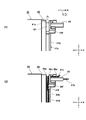
- FIG. 9 is a partial cross-sectional view showing the positional relationship between the shape of the circumferential groove 42 of FIG. 4 and the wiring of the nichrome wire 50, and (1) is a partially enlarged view of FIG.
- the diameter is d, as shown by the cross section of the nichrome wire 50 at the upper right.
- the width (length in the rotation axis A1 direction) of the circumferential groove 42 is W and the depth (depth in the radial direction of the groove) D
- the dimensions are such that W> 2d and D> 2d. It is assumed.
- the number of crossovers wired inside the circumferential groove 42 is two at the maximum.
- FIG. 9 (2) shows a state in which the nichrome wire 50 is wired in the circumferential groove 42, and it can be understood that the in-phase connecting wire 55a and the different-phase connecting wire 56c are arranged in the axial direction. You see.
- the outer edge position of the rib 41b is slightly smaller than the outer edge position of the outer peripheral surface 41a by the difference t as shown in (1).
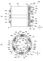
- FIG. 10 (1) is a side view of the rotor 70 and the cooling fan 13 of the motor 5, and (2) is a cross-sectional view (corresponding to a side view of the rotor core 71) of the DD part of (1).
- the assembly of the rotor 70 and the cooling fan 13 is concentric with the rotation shaft 60 on the front side of the rotor core 71 and the substantially cylindrical rotor core 71 disposed around the rotation shaft 60 serving as the central axis. It comprises the cooling fan 13 fixed.
- the rotating shaft 60 is pivotally supported by bearings 15a and 15b (see FIG. 1) at two front and rear points, and the outer peripheral surface is polished because the bearings are press-fit to the mounting portions of the bearings 15a and 15b.
- the bearing holding portions 60b and 60e with improved coaxiality are formed.
- the small diameter portion 60a for holding the bevel gear 7a (see FIG. 1) is formed on the front side of the bearing holding portion 60b, and on the rear side of the bearing holding portion 60b, on the outer peripheral surface of a part in the axial direction
- a cooling fan attachment portion 60c in which the uneven portion 60f continuous in the circumferential direction is formed is formed.
- the cooling fan 13 fixed to the cooling fan mounting portion 60c is a centrifugal fan, and when the cooling fan 13 rotates, the air taken in from the axial direction of the rotating shaft 60 is discharged radially outward.
- the cooling fan 13 is manufactured by integral molding of a synthetic resin, and an attachment portion 13a having an uneven portion corresponding to the uneven portion 60f formed on the rotary shaft 60 is formed on the inner peripheral side.
- the cooling fan 13 is fixed to the rotating shaft 60 so as to prevent idling by engagement of the unevenness.
- the stator 30 is formed of a laminated core in which a plurality of steel plates are stacked.
- the portion holding the rotor core 71 of the rotating shaft 60 is a shaft mold portion 60 d whose outer peripheral surface is covered by a mold member 65 made of an insulating material. Resin is used as the mold member 65. Since the rotor core 71 is fixed to the shaft mold portion 60d, the rotary shaft 60 and the metal portion of the rotor core 71 are connected via the mold member 65, so that electrical continuity is not established.
- balancer members 85, 95 are coaxially provided to achieve rotational balance.
- the balancer members 85 and 95 are nonmagnetic metal annular mass bodies having a predetermined thickness in the rotational axis direction, and predetermined drills in the radial direction at one or more locations in the circumferential direction of the outer peripheral surface By forming holes, grooves, chamfers and the like to reduce the local mass, the accuracy of the rotational balance of the rotating body shown in FIG. In FIG. 10 (1), small continuous grooves are formed in the circumferential direction as arrows 85a and 95a, but this makes it easy to determine the position of the tip of the drill in the axial direction when drilling. Provided in Therefore, the circumferential grooves 85a and 95a may not be provided.
- a disc-shaped resin spacer 80 is interposed between the balancer member 85 and the front end face 71a of the rotor core 71, and a disc-shaped resin spacer 90 is interposed between the balancer member 95 and the rear end face 71b of the rotor core 71.
- the outer diameter of the resin spacers 80, 90 is the same as the outer diameter of the rotor core 71, and the axial thickness is thinner than that of the resin spacers 80, 90.
- t 1 0 outside diameter only t 1 than the outer diameter of the rotor core 71 is slightly smaller, the diameter of the rotor core 71 with respect to 39.8mm spacer member (resin spacer 80, 90). It is about 5 mm.
- the diameter D 80 of the balancer member 85 for the rotor core 71 is constituted about 15% smaller, diameter D 80 of the balancer member 95 for the rotor core 71 is small composed of about 30%.
- FIG. 10 (2) is a cross-sectional view of the DD part of (1). This figure corresponds to a front view of the end face of the rotor core 71 as viewed from the front side.
- slots 73a to 73d are formed by cutting out laminated iron cores at equal intervals in the circumferential direction.
- the slots 73a to 73d are arranged on the four sides of a square centered on the rotation axis 60 in the cross section of the rotor core 71.
- four plate-like magnets 76a to 76d are press-fitted in the direction of the rotation axis A1 in the direction of the rotation axis A1, and fixed with an adhesive.
- the small diameter portions 75a to 75d continuous in the axial direction are caulking for positioning when fixing a large number of steel plates constituting the rotor core 71.
- V near the short side of each of the magnets 76a to 76d in such a manner that the outer peripheral surface of the rotor core 71 is depressed radially inward in a substantially V shape or valley shape.
- the grooved grooves 74a to 74d are formed.
- the V-shaped grooves 74a to 74d are axial grooves continuously formed from the front end surface 71a to the rear end surface 71b along the entire axial length of the rotor core 71.
- the bottom portion is flat or curved so that it can be said to be substantially U-shaped.
- the cooling air can easily pass to the outer peripheral side of the rotor core 71, and the magnetic characteristics by the magnets 76a to 76d can be improved to improve the disturbance of the magnetic flux generated from the rotor core 71.
- a mold member 65 intervenes between the center hole 72 of the rotor core 71 on the outer peripheral side of the rotating shaft 60.
- the mold member 65 is formed only on a specific portion on the outer peripheral side of the rotary shaft 60, that is, the shaft mold portion 60d. By interposing the mold member 65 in this manner, the rotor core 71 and the rotating shaft 60 are electrically insulated.
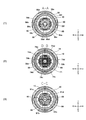
- (1) is a cross-sectional view taken along the line AA in FIG. 1, (2) is a cross-sectional view taken along the line BB in FIG. 1, and (3) is a cross-sectional view taken along the line CC in FIG. It is.
- (1) and (2) are views as viewed from the front in the direction of the rotation axis A1
- (3) is a view as viewed from the rear side. Note that the left and right directions are different.
- the stator core 31 has six pole pieces inward, and the rotor core 71 is disposed in the inner space of the pole pieces.
- the rotor core 71 is adjacent to the pole piece of the stator core 31 such that the outer peripheral surface thereof has a slight gap.
- the motor housing 10 holding the stator core 31 is formed in a cylindrical shape by integral molding of a synthetic resin, and there is no divided surface passing through the axial direction of the rotating shaft 60.
- the stator core 31 is held by being inserted rearward from the axial front side of the motor housing 10.
- a large number of axially continuous ribs (convex portions) are formed inside the motor housing 10, and a predetermined axial passage is formed outside the stator core 31 so that the cooling air flows on the outer peripheral side of the motor 5. It was made to flow from the rear in the axial direction to the front.
- the keys 32 a and 32 b of the stator core 31 are positioned in the recesses (key grooves) formed in the motor housing 10, the motor 5 is held so as not to move in the rotational direction within the motor housing 10.
- a portion AA in FIG. 11 (1) corresponds to a side view of the rotor 70 as viewed from the front side.
- a resin spacer 80 having the same cross-sectional outer edge shape as the rotor core 71 (see FIG. 10) having a V-shaped cross-sectional shape is provided on the front end surface (windward end) of the rotor core 71.
- a balancer member 85 is provided which has substantially the same diameter as the bottom of the grooves 74a to 74d. Thus, the metal surface of the front end face 71a (see FIG. 10) of the rotor core 71 is not exposed by arranging the resin spacer 80 having the same shape as the rotor core 71 having the V-shaped cross section between the balancer member 85 and the rotor core 71.
- the outer diameter of the balancer member 85 is set to be equal to or smaller than the bottom of the V-shaped grooves 74 a to 74 d of the rotor core 71 (the point closest to the rotational axis). When viewed in the normal direction of the magnet, it is formed to be smaller than the position of the outer surface of the permanent magnet.
- the balancer member 85 is on the downwind side of the rotor core 71, dust in the space surrounded by the balancer member 85 and the rotor core 71 when the outer diameter of the balancer member 85 is larger than the bottom of the V-shaped grooves 74a to 74d.
- An insulator 35 is provided on the front end side of the rotor core 71, and coils 58a to 58f are formed on wound portions extending in the radial direction of the insulator 35.
- FIG. 11 (3) is a view corresponding to a rear view of the rotor 70 as viewed from the rear side.
- the size of the balancer member 95 is a diameter sufficiently smaller than that of the rotor core 71 and the resin spacer 90.
- V-shaped grooves 91a to 91d are formed in the same manner as the outer edge shape of resin spacer 90 in the same manner as the outer edge shape of rotor core 71, so the metal surface of rear end face 71b (see FIG. 10) of rotor core 71 is not exposed. It is possible to prevent metal dust that has reached the inner space of the motor housing 10 from the inside of the handle housing 16 with the cooling air from adhering directly to the axial rear end surface 71b of the rotor core 71.
- V-shaped groove is similarly formed in the resin spacer 90, the possibility of causing the motor lock due to the foreign matter attached to the end face of the rotor core 71 is substantially avoided without obstructing the flow of the cooling air in the axial direction. it can.
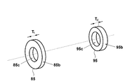
- FIG. 12 is a perspective view showing the shape of the balancer members 85 and 95 alone.
- the balancer members 85 and 95 are for the purpose of improving the rotational balance of the rotor 70, and therefore have an axially symmetrical substantially annular shape in the state before the radial adjustment holes for balance adjustment (the state before the balance adjustment).
- Through holes 85 c and 95 c are formed at the centers of the respective members, and have thicknesses T 1 and T 2 in the axial direction.
- the respective masses are equalized by setting T 1 ⁇ T 2 in consideration of the difference in outer diameter.
- the inner diameter of the through holes 85c and 95c is set to an optimum size for press-fitting the shaft mold portion 60d (see FIG. 10) of the rotating shaft 60 after the shaft molding process is completed.
- a not-shown drill blade is pushed against the outer peripheral surface of the balancer members 85 and 95 from the radial direction of the rotating shaft 60. It is applied to form minute holes in it so that the mass reduction of the metal part removed by the holes will eliminate irregularities in the mass distribution of the rotating body.
- the drill since the drill is made of iron-based metal, it is attracted by the magnetic force to the magnets 76a to 76d provided on the rotor core 71, so that the drilling operation is likely to be hindered.
- the resin spacers 80 and 90 in the present embodiment, the distance between the balancer members 85 and 95 and the rotor core 71 can be slightly separated, so that the workability of the balancing operation can be improved. Even if the drill bit is drawn to the end face of the rotor core 71, the presence of the resin spacers 80 and 90 makes it easier to separate than in the conventional case.
- the resin spacers 80 and 90 are formed by integrally molding the rotary shaft 60 and the both end surfaces of the rotor core 71 by including the both end surfaces of the rotor core 71 as mold parts. It may be molded integrally with the mold member 65.
- the basic structure of the second embodiment is the same as that of the first embodiment, except that the axial length of the stator core 131 is large and the shape of the second insulator 140 on the rear side is different.
- the front side insulator 35 can use the same component as that of the first embodiment if the size of the annular portion 36 matches.
- the insulator 140 not only realizes the delta connection method according to the present invention, but also has a total of six coil extraction parts 146 to 148 and 166 to 168 so as to be widely compatible with conventional star connection and the like. It is.
- the circumferential groove 142 is formed on the outer peripheral surface 141 a of the insulator 140 according to the same idea as the first embodiment described above.
- the circumferential groove 142 is a recess that is recessed in the radial direction, and is formed continuously in the circumferential direction. Further, radial grooves 143a to 143f are formed such that the annular end surface 141c and the rib 141b are cut in the direction of the rotation axis A1 so as to cross the circumferential groove 142.
- the radial grooves 143a to 143f are formed clockwise of the wound portions 158a to 158f of the insulator 140 as viewed from the rear side in the direction of the rotation axis A1. Further, lead portions 146 to 148 and 166 to 168 are formed on the radially outer side of the wound portions 158 a to 158 f, respectively. Here, only the lead portions 146 to 148 are used, and the lead portions 166 to 168 are not used for winding and wiring of a coil. Note that which of the lead-out portions is used may be changed according to the shape of the housing portion to which the motor is attached and the position of the wiring for driving current to the motor.
- the metal terminals 159a to 159c are attached to the lead portions 146 to 148, respectively, and the different phase connecting wires 156a to 156c are brought into contact with the metal terminals 159a to 159c and fixed in a conductive state.
- a metal terminal 159 c is attached to the lead-out portion 147.
- a coil wire holding portion 160c in which a cut out portion is bent outward is formed in a part of the metal terminal 159c, and the different phase crossover wire 156a is locked to the coil wire holding portion 160c.
- wound portions 158a to 158f are members that cover the rear sides in the circumferential direction of the teeth of the stator core 131, and insulate between the coil and the teeth.
- the coils of the motor are delta connected, and the shape of one end side (rear side) of the stator core is devised to efficiently wind using a coil automatic winding machine. It became possible. Further, since the circumferential crossover wires in the insulator 40 are wired so as not to be exposed to the cooling air, the power tool can be realized which has a long life and operates stably even in an environment where the metal powder is scattered. .
- the power tool is not limited to the above-described grinder, and application to various other power tools using a motor is possible.
- the present invention can be applied to other power machines and motors for power machines.
- Irregularities (rotational axis) 65 mold member 70: rotor 71: rotor core 71a: front end face 71b: rear end face 71c: outer peripheral surface 72: central hole 73a to 73d slot 74a to 74d V-shaped groove 75a to 75d small diameter portion 76a to 76d magnet 80 resin spacer 80a through hole 80b outer circumferential surface 85 balancer member 85a circumferential groove 90 ... Resin spacer, 90a ... through hole, 91a to 91d ... (V of the resin spacer 90), 95 ... balancer member, 95a ... circumferential groove, 98 ... grindstone, 99 ... power cord, 100 ... commercial AC power supply, 101 ...
- Fan housing portion 102 Motor housing portion 103: Taper portion 104: Circuit board housing portion 105a: Screw boss portion 106a to 106d: Screw boss, 107a, 107b: Rib, 108: Rail portion, 109: Bearing holder, DESCRIPTION OF SYMBOLS 110 ... Operation part, 111 ... Rectification circuit, 112 ... Bridge diode, 113 ... Smoothing circuit, 114 ... Electrolytic capacitor, 115 ... Capacitor, 116 ... Resistance, 117 ... Shunt resistance, 118 ... Inverter circuit, 119 ...
- Low voltage power circuit 121: Hall IC, 122: sensor substrate, 125: intermediate member, 125a: rotational groove, 126: surface An encircling portion 130, a stator 131, a stator core 133, a support member 133a, a right side portion 133b, a left side portion 134a, a through hole 135a, a wind window 136a, a member 137a, a screw hole 140, an insulator 141a.
Landscapes
- Engineering & Computer Science (AREA)
- Mechanical Engineering (AREA)
- Power Engineering (AREA)
- Portable Power Tools In General (AREA)
- Connection Of Motors, Electrical Generators, Mechanical Devices, And The Like (AREA)
- Motor Or Generator Cooling System (AREA)
- Finish Polishing, Edge Sharpening, And Grinding By Specific Grinding Devices (AREA)
Abstract
La présente invention concerne un outil électrique qui peut empêcher l'adhérence de poudre, par exemple de la poudre de fer, aux bords d'un noyau de stator. L'outil électrique comprend : un moteur ayant un noyau de rotor (71) qui utilise un aimant permanent monté sur un arbre rotatif (60) ; un ventilateur de refroidissement (13) ; un logement de moteur servant à loger le moteur et le ventilateur de refroidissement, l'air extérieur étant aspiré à l'aide du ventilateur de refroidissement (13) de façon à amener l'air de refroidissement à circuler dans la direction de l'arbre rotatif (60) dans le logement de moteur. Des éléments d'équilibrage métalliques non magnétiques (85, 95) de forme cylindrique et d'un diamètre externe inférieur à celui du noyau de rotor (71), sont disposés sur les deux extrémités du noyau de rotor (71) dans la direction axiale. En outre, des éléments d'espacement en résine (80, 90) sont disposés entre le noyau de rotor (71) et les éléments d'équilibrage (85, 95). Une pluralité de rainures, orientées de façon axiale (74a-74d) sensiblement en V, sont formées sur la surface circonférentielle externe (71c) du noyau de rotor (71), alors que les éléments d'espacement (80, 90) sont également configurés de façon à présenter sensiblement le même profil que le noyau de rotor (71) de manière à pouvoir recouvrir une partie métallique des faces d'extrémité (71a, 71b) du noyau de rotor (71).
Priority Applications (1)
| Application Number | Priority Date | Filing Date | Title |
|---|---|---|---|
| JP2019557031A JP7031684B2 (ja) | 2017-11-30 | 2018-09-28 | 電動工具 |
Applications Claiming Priority (2)
| Application Number | Priority Date | Filing Date | Title |
|---|---|---|---|
| JP2017230258 | 2017-11-30 | ||
| JP2017-230258 | 2017-11-30 |
Publications (1)
| Publication Number | Publication Date |
|---|---|
| WO2019106934A1 true WO2019106934A1 (fr) | 2019-06-06 |
Family
ID=66663950
Family Applications (1)
| Application Number | Title | Priority Date | Filing Date |
|---|---|---|---|
| PCT/JP2018/036310 Ceased WO2019106934A1 (fr) | 2017-11-30 | 2018-09-28 | Outil électrique |
Country Status (2)
| Country | Link |
|---|---|
| JP (1) | JP7031684B2 (fr) |
| WO (1) | WO2019106934A1 (fr) |
Cited By (3)
| Publication number | Priority date | Publication date | Assignee | Title |
|---|---|---|---|---|
| JP2021053736A (ja) * | 2019-09-30 | 2021-04-08 | 工機ホールディングス株式会社 | 動力工具 |
| WO2023282176A1 (fr) * | 2021-07-08 | 2023-01-12 | 株式会社明電舎 | Moteur à entrefer axial |
| JP2023054752A (ja) * | 2021-10-04 | 2023-04-14 | 株式会社マキタ | 携帯用加工機 |
Families Citing this family (1)
| Publication number | Priority date | Publication date | Assignee | Title |
|---|---|---|---|---|
| EP4317701A4 (fr) * | 2021-03-30 | 2024-09-25 | Panasonic Intellectual Property Management Co., Ltd. | Soufflante d'air électrique et ventilateur |
Citations (3)
| Publication number | Priority date | Publication date | Assignee | Title |
|---|---|---|---|---|
| JP2008187760A (ja) * | 2007-01-26 | 2008-08-14 | Matsushita Electric Works Ltd | モータ及びインパクト回転工具 |
| JP2013099038A (ja) * | 2011-10-28 | 2013-05-20 | Mitsuba Corp | 電動機用ロータおよびブラシレスモータ |
| JP2015126562A (ja) * | 2013-12-25 | 2015-07-06 | 株式会社マキタ | 電動工具 |
Family Cites Families (2)
| Publication number | Priority date | Publication date | Assignee | Title |
|---|---|---|---|---|
| JP2003274587A (ja) | 2002-03-19 | 2003-09-26 | Toyota Motor Corp | 永久磁石型モータ |
| JP5722156B2 (ja) | 2011-08-02 | 2015-05-20 | 株式会社マキタ | 電動工具 |
-
2018
- 2018-09-28 WO PCT/JP2018/036310 patent/WO2019106934A1/fr not_active Ceased
- 2018-09-28 JP JP2019557031A patent/JP7031684B2/ja active Active
Patent Citations (3)
| Publication number | Priority date | Publication date | Assignee | Title |
|---|---|---|---|---|
| JP2008187760A (ja) * | 2007-01-26 | 2008-08-14 | Matsushita Electric Works Ltd | モータ及びインパクト回転工具 |
| JP2013099038A (ja) * | 2011-10-28 | 2013-05-20 | Mitsuba Corp | 電動機用ロータおよびブラシレスモータ |
| JP2015126562A (ja) * | 2013-12-25 | 2015-07-06 | 株式会社マキタ | 電動工具 |
Cited By (4)
| Publication number | Priority date | Publication date | Assignee | Title |
|---|---|---|---|---|
| JP2021053736A (ja) * | 2019-09-30 | 2021-04-08 | 工機ホールディングス株式会社 | 動力工具 |
| WO2023282176A1 (fr) * | 2021-07-08 | 2023-01-12 | 株式会社明電舎 | Moteur à entrefer axial |
| JP2023009830A (ja) * | 2021-07-08 | 2023-01-20 | 株式会社明電舎 | アキシャルギャップモータ |
| JP2023054752A (ja) * | 2021-10-04 | 2023-04-14 | 株式会社マキタ | 携帯用加工機 |
Also Published As
| Publication number | Publication date |
|---|---|
| JP7031684B2 (ja) | 2022-03-08 |
| JPWO2019106934A1 (ja) | 2020-10-08 |
Similar Documents
| Publication | Publication Date | Title |
|---|---|---|
| JP6973479B2 (ja) | 電動工具 | |
| WO2019106934A1 (fr) | Outil électrique | |
| US9692270B2 (en) | Motor including brackets and fixing members | |
| EP3287240B1 (fr) | Outil électrique | |
| JP2000060091A (ja) | 回転電機 | |
| CN106470804A (zh) | 电动工具 | |
| JPWO2020003696A1 (ja) | 電動工具 | |
| JP5482274B2 (ja) | 電動工具 | |
| CN106488830A (zh) | 电动工具 | |
| CN107112815A (zh) | 无刷电动机以及电动工具 | |
| US12266986B2 (en) | Brushless motor and electrically-powered tool | |
| JP6851735B2 (ja) | 電動工具 | |
| WO2021065273A1 (fr) | Outil électrique | |
| JP2021062444A (ja) | 動力工具 | |
| WO2019151395A1 (fr) | Moteur sans balais et appareil électrique l'utilisant | |
| JP2019103211A (ja) | モータ及びそれを用いた電動工具 | |
| JP2017013141A (ja) | 電動工具 | |
| WO2020203294A1 (fr) | Stator et moteur électrique | |
| JP2021053736A (ja) | 動力工具 | |
| JP2016022555A (ja) | 電動工具 | |
| JP2017013142A (ja) | 電動工具 | |
| WO2022091964A1 (fr) | Machine de travail | |
| JP2017017770A (ja) | 電動工具 | |
| CN210629286U (zh) | 角磨及其电机 | |
| JP2021053737A (ja) | 動力工具 |
Legal Events
| Date | Code | Title | Description |
|---|---|---|---|
| 121 | Ep: the epo has been informed by wipo that ep was designated in this application |
Ref document number: 18884024 Country of ref document: EP Kind code of ref document: A1 |
|
| ENP | Entry into the national phase |
Ref document number: 2019557031 Country of ref document: JP Kind code of ref document: A |
|
| NENP | Non-entry into the national phase |
Ref country code: DE |
|
| 122 | Ep: pct application non-entry in european phase |
Ref document number: 18884024 Country of ref document: EP Kind code of ref document: A1 |