WO2019106955A1 - 液体ブロー成形方法 - Google Patents
液体ブロー成形方法 Download PDFInfo
- Publication number
- WO2019106955A1 WO2019106955A1 PCT/JP2018/037104 JP2018037104W WO2019106955A1 WO 2019106955 A1 WO2019106955 A1 WO 2019106955A1 JP 2018037104 W JP2018037104 W JP 2018037104W WO 2019106955 A1 WO2019106955 A1 WO 2019106955A1
- Authority
- WO
- WIPO (PCT)
- Prior art keywords
- liquid
- preform
- gas
- blow molding
- nozzle
- Prior art date
- Legal status (The legal status is an assumption and is not a legal conclusion. Google has not performed a legal analysis and makes no representation as to the accuracy of the status listed.)
- Ceased
Links
Images



Classifications
-
- B—PERFORMING OPERATIONS; TRANSPORTING
- B29—WORKING OF PLASTICS; WORKING OF SUBSTANCES IN A PLASTIC STATE IN GENERAL
- B29C—SHAPING OR JOINING OF PLASTICS; SHAPING OF MATERIAL IN A PLASTIC STATE, NOT OTHERWISE PROVIDED FOR; AFTER-TREATMENT OF THE SHAPED PRODUCTS, e.g. REPAIRING
- B29C49/00—Blow-moulding, i.e. blowing a preform or parison to a desired shape within a mould; Apparatus therefor
- B29C49/42—Component parts, details or accessories; Auxiliary operations
- B29C49/46—Component parts, details or accessories; Auxiliary operations characterised by using particular environment or blow fluids other than air
-
- B—PERFORMING OPERATIONS; TRANSPORTING
- B29—WORKING OF PLASTICS; WORKING OF SUBSTANCES IN A PLASTIC STATE IN GENERAL
- B29C—SHAPING OR JOINING OF PLASTICS; SHAPING OF MATERIAL IN A PLASTIC STATE, NOT OTHERWISE PROVIDED FOR; AFTER-TREATMENT OF THE SHAPED PRODUCTS, e.g. REPAIRING
- B29C49/00—Blow-moulding, i.e. blowing a preform or parison to a desired shape within a mould; Apparatus therefor
- B29C49/08—Biaxial stretching during blow-moulding
- B29C49/10—Biaxial stretching during blow-moulding using mechanical means for prestretching
- B29C49/122—Drive means therefor
-
- B—PERFORMING OPERATIONS; TRANSPORTING
- B29—WORKING OF PLASTICS; WORKING OF SUBSTANCES IN A PLASTIC STATE IN GENERAL
- B29C—SHAPING OR JOINING OF PLASTICS; SHAPING OF MATERIAL IN A PLASTIC STATE, NOT OTHERWISE PROVIDED FOR; AFTER-TREATMENT OF THE SHAPED PRODUCTS, e.g. REPAIRING
- B29C49/00—Blow-moulding, i.e. blowing a preform or parison to a desired shape within a mould; Apparatus therefor
- B29C49/42—Component parts, details or accessories; Auxiliary operations
- B29C49/58—Blowing means
-
- B—PERFORMING OPERATIONS; TRANSPORTING
- B65—CONVEYING; PACKING; STORING; HANDLING THIN OR FILAMENTARY MATERIAL
- B65B—MACHINES, APPARATUS OR DEVICES FOR, OR METHODS OF, PACKAGING ARTICLES OR MATERIALS; UNPACKING
- B65B3/00—Packaging plastic material, semiliquids, liquids or mixed solids and liquids, in individual containers or receptacles, e.g. bags, sacks, boxes, cartons, cans, or jars
- B65B3/02—Machines characterised by the incorporation of means for making the containers or receptacles
- B65B3/022—Making containers by moulding of a thermoplastic material
-
- B—PERFORMING OPERATIONS; TRANSPORTING
- B65—CONVEYING; PACKING; STORING; HANDLING THIN OR FILAMENTARY MATERIAL
- B65B—MACHINES, APPARATUS OR DEVICES FOR, OR METHODS OF, PACKAGING ARTICLES OR MATERIALS; UNPACKING
- B65B3/00—Packaging plastic material, semiliquids, liquids or mixed solids and liquids, in individual containers or receptacles, e.g. bags, sacks, boxes, cartons, cans, or jars
- B65B3/18—Controlling escape of air from containers or receptacles during filling
-
- B—PERFORMING OPERATIONS; TRANSPORTING
- B29—WORKING OF PLASTICS; WORKING OF SUBSTANCES IN A PLASTIC STATE IN GENERAL
- B29C—SHAPING OR JOINING OF PLASTICS; SHAPING OF MATERIAL IN A PLASTIC STATE, NOT OTHERWISE PROVIDED FOR; AFTER-TREATMENT OF THE SHAPED PRODUCTS, e.g. REPAIRING
- B29C49/00—Blow-moulding, i.e. blowing a preform or parison to a desired shape within a mould; Apparatus therefor
- B29C49/42—Component parts, details or accessories; Auxiliary operations
- B29C2049/4294—Sealing means
-
- B—PERFORMING OPERATIONS; TRANSPORTING
- B29—WORKING OF PLASTICS; WORKING OF SUBSTANCES IN A PLASTIC STATE IN GENERAL
- B29C—SHAPING OR JOINING OF PLASTICS; SHAPING OF MATERIAL IN A PLASTIC STATE, NOT OTHERWISE PROVIDED FOR; AFTER-TREATMENT OF THE SHAPED PRODUCTS, e.g. REPAIRING
- B29C49/00—Blow-moulding, i.e. blowing a preform or parison to a desired shape within a mould; Apparatus therefor
- B29C49/42—Component parts, details or accessories; Auxiliary operations
- B29C49/46—Component parts, details or accessories; Auxiliary operations characterised by using particular environment or blow fluids other than air
- B29C2049/4602—Blowing fluids
- B29C2049/465—Blowing fluids being incompressible
- B29C2049/4664—Blowing fluids being incompressible staying in the final article
-
- B—PERFORMING OPERATIONS; TRANSPORTING
- B29—WORKING OF PLASTICS; WORKING OF SUBSTANCES IN A PLASTIC STATE IN GENERAL
- B29C—SHAPING OR JOINING OF PLASTICS; SHAPING OF MATERIAL IN A PLASTIC STATE, NOT OTHERWISE PROVIDED FOR; AFTER-TREATMENT OF THE SHAPED PRODUCTS, e.g. REPAIRING
- B29C49/00—Blow-moulding, i.e. blowing a preform or parison to a desired shape within a mould; Apparatus therefor
- B29C49/42—Component parts, details or accessories; Auxiliary operations
- B29C49/58—Blowing means
- B29C2049/5862—Drive means therefore
-
- B—PERFORMING OPERATIONS; TRANSPORTING
- B29—WORKING OF PLASTICS; WORKING OF SUBSTANCES IN A PLASTIC STATE IN GENERAL
- B29C—SHAPING OR JOINING OF PLASTICS; SHAPING OF MATERIAL IN A PLASTIC STATE, NOT OTHERWISE PROVIDED FOR; AFTER-TREATMENT OF THE SHAPED PRODUCTS, e.g. REPAIRING
- B29C49/00—Blow-moulding, i.e. blowing a preform or parison to a desired shape within a mould; Apparatus therefor
- B29C49/42—Component parts, details or accessories; Auxiliary operations
- B29C49/58—Blowing means
- B29C2049/5893—Mounting, exchanging or centering blowing means
-
- B—PERFORMING OPERATIONS; TRANSPORTING
- B29—WORKING OF PLASTICS; WORKING OF SUBSTANCES IN A PLASTIC STATE IN GENERAL
- B29C—SHAPING OR JOINING OF PLASTICS; SHAPING OF MATERIAL IN A PLASTIC STATE, NOT OTHERWISE PROVIDED FOR; AFTER-TREATMENT OF THE SHAPED PRODUCTS, e.g. REPAIRING
- B29C2949/00—Indexing scheme relating to blow-moulding
- B29C2949/07—Preforms or parisons characterised by their configuration
- B29C2949/0715—Preforms or parisons characterised by their configuration the preform having one end closed
-
- B—PERFORMING OPERATIONS; TRANSPORTING
- B29—WORKING OF PLASTICS; WORKING OF SUBSTANCES IN A PLASTIC STATE IN GENERAL
- B29C—SHAPING OR JOINING OF PLASTICS; SHAPING OF MATERIAL IN A PLASTIC STATE, NOT OTHERWISE PROVIDED FOR; AFTER-TREATMENT OF THE SHAPED PRODUCTS, e.g. REPAIRING
- B29C49/00—Blow-moulding, i.e. blowing a preform or parison to a desired shape within a mould; Apparatus therefor
- B29C49/02—Combined blow-moulding and manufacture of the preform or the parison
- B29C49/06—Injection blow-moulding
-
- B—PERFORMING OPERATIONS; TRANSPORTING
- B29—WORKING OF PLASTICS; WORKING OF SUBSTANCES IN A PLASTIC STATE IN GENERAL
- B29C—SHAPING OR JOINING OF PLASTICS; SHAPING OF MATERIAL IN A PLASTIC STATE, NOT OTHERWISE PROVIDED FOR; AFTER-TREATMENT OF THE SHAPED PRODUCTS, e.g. REPAIRING
- B29C49/00—Blow-moulding, i.e. blowing a preform or parison to a desired shape within a mould; Apparatus therefor
- B29C49/42—Component parts, details or accessories; Auxiliary operations
- B29C49/4289—Valve constructions or configurations, e.g. arranged to reduce blowing fluid consumption
-
- B—PERFORMING OPERATIONS; TRANSPORTING
- B29—WORKING OF PLASTICS; WORKING OF SUBSTANCES IN A PLASTIC STATE IN GENERAL
- B29K—INDEXING SCHEME ASSOCIATED WITH SUBCLASSES B29B, B29C OR B29D, RELATING TO MOULDING MATERIALS OR TO MATERIALS FOR MOULDS, REINFORCEMENTS, FILLERS OR PREFORMED PARTS, e.g. INSERTS
- B29K2023/00—Use of polyalkenes or derivatives thereof as moulding material
- B29K2023/04—Polymers of ethylene
- B29K2023/06—PE, i.e. polyethylene
-
- B—PERFORMING OPERATIONS; TRANSPORTING
- B29—WORKING OF PLASTICS; WORKING OF SUBSTANCES IN A PLASTIC STATE IN GENERAL
- B29K—INDEXING SCHEME ASSOCIATED WITH SUBCLASSES B29B, B29C OR B29D, RELATING TO MOULDING MATERIALS OR TO MATERIALS FOR MOULDS, REINFORCEMENTS, FILLERS OR PREFORMED PARTS, e.g. INSERTS
- B29K2023/00—Use of polyalkenes or derivatives thereof as moulding material
- B29K2023/10—Polymers of propylene
- B29K2023/12—PP, i.e. polypropylene
-
- B—PERFORMING OPERATIONS; TRANSPORTING
- B29—WORKING OF PLASTICS; WORKING OF SUBSTANCES IN A PLASTIC STATE IN GENERAL
- B29K—INDEXING SCHEME ASSOCIATED WITH SUBCLASSES B29B, B29C OR B29D, RELATING TO MOULDING MATERIALS OR TO MATERIALS FOR MOULDS, REINFORCEMENTS, FILLERS OR PREFORMED PARTS, e.g. INSERTS
- B29K2067/00—Use of polyesters or derivatives thereof, as moulding material
- B29K2067/003—PET, i.e. poylethylene terephthalate
-
- B—PERFORMING OPERATIONS; TRANSPORTING
- B29—WORKING OF PLASTICS; WORKING OF SUBSTANCES IN A PLASTIC STATE IN GENERAL
- B29L—INDEXING SCHEME ASSOCIATED WITH SUBCLASS B29C, RELATING TO PARTICULAR ARTICLES
- B29L2031/00—Other particular articles
- B29L2031/712—Containers; Packaging elements or accessories, Packages
- B29L2031/7158—Bottles
Definitions
- the present invention relates to a liquid blow molding method for forming a synthetic resin preform having a mouth into a liquid-containing container of a predetermined shape.
- Containers made of synthetic resin as typified by bottles made of polypropylene (PP) and bottles made of polyethylene terephthalate (PET) contain various liquids such as beverages, cosmetics, medicines, detergents, and toiletries such as shampoo as content liquids Used for housing applications.
- PP polypropylene
- PET polyethylene terephthalate
- Such a container is generally manufactured by blow-molding, for example, a preform formed in a bottomed cylindrical shape from a synthetic resin material having thermoplasticity as described above.
- blow molding for forming a preform into a container liquid blow molding in which a pressurized liquid is used instead of pressurized air as a pressurized medium supplied to the inside of the preform is known.
- Patent Document 1 a preform made of a synthetic resin, which has been heated to a temperature at which stretchability is expressed in advance, is set in a mold for blow molding, and a predetermined pressure is introduced through the blow nozzle inside the preform.
- a liquid blow molding method is described in which the preform is formed into a container of a predetermined shape along the cavity of a mold by supplying a liquid pressurized to a maximum. According to such a liquid blow molding method, by using the content liquid to be finally contained in the container as a product such as a beverage as the liquid to be supplied to the preform, the molding of the container and the content liquid to the container can be performed.
- filling can be performed at the same time to easily form (manufacture) a liquid-filled container containing the content liquid, thereby omitting the step of filling the content liquid into the interior of the container after molding and producing the same
- the configuration of the process and production line (apparatus) can be simplified.
- Patent No. 5806929 gazette
- This invention is made in view of such a subject,
- the objective is the liquid blow which can manufacture a liquid containing container precisely and low cost so that it may have a predetermined
- the liquid blow molding method according to the present invention is a liquid blow molding method for forming a synthetic resin preform having a mouth into a liquid-containing container having a predetermined shape, and the inside of the preform is made from the mouth through a blow nozzle.
- liquid blow molding method of the present invention in the above-described configuration, it is preferable to perform the gas-liquid separation step while performing the gas-liquid replacement step.
- liquid blow molding method of the present invention in the above configuration, it is preferable to perform the gas-liquid separation step after the completion of the gas-liquid replacement step.
- the preform is gripped by a grip portion provided on the blow nozzle to rotate the preform together with the grip portion.
- the liquid blow molding method has a nozzle engagement step of engaging the blow nozzle with the opening before the gas-liquid replacement step in the above configuration, and the blow-liquid replacement step includes the step of: While the liquid is supplied from the opening to the inside of the preform through the liquid supply port of the nozzle, the air inside the preform is discharged to the outside from the discharge port provided in the blow nozzle separately from the liquid supply port. It is preferable to
- the method further includes a first nozzle lowering step of lowering the blow nozzle to a first position not sealing the port before the gas-liquid replacement step;
- a first nozzle lowering step of lowering the blow nozzle to a first position not sealing the port before the gas-liquid replacement step In the liquid replacement step, while the liquid is supplied from the opening to the inside of the preform through the blow nozzle at the first position, the air inside the preform is extracted from the gap between the blow nozzle and the opening.
- the liquid blow molding method according to the present invention preferably has a suck back step of sucking back a predetermined amount of liquid from the inside of the container after molding through the blow nozzle after the blow molding step in the above configuration.
- the present invention it is possible to provide a liquid blow molding method that can be manufactured precisely and at low cost so that the liquid-filled container has a predetermined internal volume and shape.
- the liquid blow molding method of the present invention is a liquid blow molding method of molding a synthetic resin preform having a mouth into a liquid-containing container of a predetermined shape, and a liquid is introduced into the preform from the mouth through a blow nozzle.
- a blow molding step of supplying pressurized liquid from the mouth to the inside of the preform through the blow nozzle to form the preform into a container of a predetermined shape. It is.
- Such a liquid blow molding method of the present invention can also be said to be a method of manufacturing a liquid-filled container for manufacturing a liquid-filled container containing a content liquid from a preform.
- the liquid blow molding method of the present invention can be carried out using, for example, the liquid blow molding device 1 configured as shown in FIG.
- the liquid blow molding apparatus 1 shown in FIG. 1 is a liquid blow molding of a preform 2 made of synthetic resin, and molded into a liquid-containing container containing a content liquid inside.
- the liquid blow molding is a blow molding performed using a pressurized liquid instead of pressurized air used in air blow molding as a pressure medium (pressure fluid) supplied to the preform 2. It is.
- liquid L supplied to the preform 2 that is, the content liquid L contained in the liquid-containing container after molding
- various liquids such as beverages, cosmetics, medicines, detergents, and toiletries such as shampoo can be used, for example.
- thermoplastic synthetic resin material such as polypropylene (PP) or polyethylene terephthalate (PET) is connected to the cylindrical opening 2a serving as the opening end and the opening 2a and the lower end is closed. It is preferable to use one formed in a bottomed cylindrical shape having a cylindrical body 2b.
- the preform 2 if it has the opening part 2a not only the thing of the said shape, the thing of various shapes can be used according to the shape etc. of the container after shaping
- a closure cap (not shown) is attached to the opening 2a of the liquid container after molding by undercutting (under cut engagement)
- An engagement protrusion is provided on the outer wall surface of the opening 2a.
- a male screw may be provided to attach the closure cap to the opening 2a by screw connection.
- the liquid blow molding apparatus 1 has a mold 10 for blow molding.
- the mold 10 has a cavity 11 having a shape corresponding to the final shape of the container, for example, a bottle shape.
- the cavity 11 opens upward at the upper surface of the mold 10.
- the preform 2 is mounted on the mold 10 in a state where the body 2 b is disposed inside the cavity 11 of the mold 10 and the opening 2 a protrudes upward from the mold 10.
- the mold 10 can be opened to the left and right, and after the preform 2 is formed into a liquid-filled container, the liquid-filled container is removed from the mold 10 by opening the mold 10 to the left and right. be able to.
- the nozzle unit 20 for supplying the liquid L to the inside of the preform 2 is provided.
- the nozzle unit 20 has a main body block 21 which is movable relative to the mold 10 in the vertical direction.
- a support block 22 is provided at the lower end of the main body block 21, and is supported by the support block 22, and a blow nozzle 23 is mounted at the lower end of the main body block 21.
- the blow nozzle 23 is formed in a substantially cylindrical shape, and is a preform attached to the mold 10 when the nozzle unit 20 moves relative to the mold 10 to the stroke end in the direction approaching the mold 10. It engages with the mouth 2 of 2 from the upper side in a sealing state.
- the inner part of the cylindrical part of the blow nozzle 23 is a liquid supply port 23a. Further, the cylindrical portion constituting the liquid supply port 23a of the blow nozzle 23 is provided with a discharge port 23b opened at the lower end of the cylindrical portion. In the present embodiment, eight discharge ports 23 b are provided at equal intervals in the circumferential direction in the cylindrical portion of the blow nozzle 23, but the number can be changed variously.
- a supply path 24 extending in the vertical direction is provided inside the main body block 21.
- the supply path 24 is a flow path for supplying the liquid L to the liquid supply port 23 a of the blow nozzle 23, and the lower end thereof communicates with the liquid supply port 23 a of the blow nozzle 23.
- the main body block 21 is provided with a supply port 25 communicating with the upper end of the supply path 24.
- a seal body 26 for opening and closing the liquid supply port 23 a of the blow nozzle 23 is disposed in the supply path 24.
- the seal body 26 is fixed to the lower end of a shaft body 27 provided to be movable in the vertical direction with respect to the nozzle unit 20, and is movable in the vertical direction inside the supply passage 24.
- the seal body 26 is formed in a cylindrical shape and abuts on the upper surface of the blow nozzle 23 at the lower end face when moving to the closed position which is the lower stroke end position to close the liquid supply port 23a of the blow nozzle 23 Do.
- the seal body 26 moves upward from the closed position, the liquid supply port 23 a of the blow nozzle 23 is opened and communicated with the supply path 24.
- the seal body 26 may be formed integrally with the shaft body 27.
- the liquid blow molding apparatus 1 can also be configured with a draw rod 28.
- the extension rod 28 is inserted in the axial center of the shaft body 27 so as to be movable relative to the shaft body 27 in the vertical direction, penetrates the axial center of the seal body 26 and can project from the lower end of the seal body 26 It is provided.
- the preform 2 can be axially stretched by moving the stretching rod 28 downward by being driven by a drive source (not shown).
- the liquid blow molding device 1 applies the pressurized liquid L supplied from the opening 2 a while stretching the preform 2 in the axial direction by the extension rod 28.
- the liquid blow molding apparatus 1 may be configured to perform liquid blow molding only with the liquid L in which the preform 2 is pressurized without providing the drawing rod 28.
- the pump 30 is connected to the supply port 25 by a pipe P1.
- the pump 30 can be configured, for example, as a plunger pump including a cylinder 30a and a piston (plunger) 30b.
- a supply tank 31 is connected to the pump 30.
- the supply tank 31 can be configured to store the liquid L and to heat the liquid L to a predetermined temperature and maintain the temperature at the predetermined temperature.
- An on-off valve V1 is provided in a flow passage between the pump 30 and the supply tank 31, and the on-off valve V1 can open and close the flow passage.
- symbol 32 is a pressure gauge provided in piping P1.
- the plurality of discharge ports 23 b provided in the blow nozzle 23 are connected to the connection passage 23 c annularly provided on the outer peripheral surface of the blow nozzle 23 by a flow passage extending upward and bending outward in the radial direction. It is in communication.
- the connection path 23 c is connected to the connection port 22 a on the side surface of the support block 22.
- a pipe P2 is connected to the connection port 22a, and the connection port 22a is connected to a discharge tank (not shown) via the pipe P2. That is, the plurality of discharge ports 23 b provided in the blow nozzle 23 are connected to the discharge tank, respectively.
- the pipe P2 may be connected to a suction pump for discharge instead of the discharge tank.
- the pipe P2 is provided with an on-off valve V2 for opening and closing the pipe P2.
- the pump 30 is pressurized to a predetermined pressure by operating in the positive direction (pressing direction) in a state where the seal body 26 moves upward and the liquid supply port 23a is opened and the on-off valve V1 is closed.
- the liquid L can be supplied to the inside of the preform 2 through the pipe P1, the supply port 25, the supply path 24, and the liquid supply port 23a of the blow nozzle 23.
- the liquid supply port 23a is closed by the seal body 26 and the on / off valve V1 is opened in the reverse direction to operate the liquid L stored in the supply tank 31 inside the cylinder 30a. To prepare for the next liquid blow molding.
- the liquid blow molding device 1 is provided with a rotation drive unit 40 for rotating the preform 2 mounted on the mold 10 about the axial center of the opening 2a.
- the rotary drive unit 40 is provided on the outer peripheral surface of the distal end portion of the blow nozzle 23 so as to be rotatable relative to the distal end portion and the opening 2 a of the preform 2. It has a gripping portion 40a which can be gripped from the inside, and a drive mechanism 40b which is disposed radially outside the gripping portion 40a with the opening 2a of the preform 2 interposed therebetween, and which rotationally drives the gripping portion 40a.
- the drive mechanism 40b can transmit the driving force from a drive source (not shown) such as an electric motor to the grip portion 40a.
- the rotary drive unit 40 having such a configuration rotates the grip portion 40a by the drive mechanism 40b in a state where the grip portion 40a grips the mouth portion 2a of the preform 2, thereby opening the preform 2 together with the grip portion 40a.
- the center of the axis of the part 2a can be rotated.
- the gripping portion 40a is a seal that grips the opening 2a in a state of being in fluid tight contact with the inner surface of the opening 2a of the preform 2 and prevents liquid leakage from the opening 2a of the preform 2 Also works.
- the rotation speed of the preform 2 by the rotation drive unit 40 is appropriately set according to the type, viscosity, and the like of the liquid L.
- the preform 2 is formed by rotating the holding portion 40a provided at the tip end side portion of the blow nozzle 23 for holding the mouth 2a of the preform 2 by the drive mechanism 40b.
- the configuration is such that the center of the axis of the portion 2a is rotated, but the configuration is not limited to this, and the configuration can be changed variously as long as the preform 2 can be rotated about the axis of the opening 2a.
- a bottom pin is provided which protrudes from the bottom portion of the mold 10 toward the inside of the cavity 11, and the bottom pin of the preform 2 is gripped by the bottom pin and the preform 2 is opened by rotating the bottom pin. It may be configured to rotate around the axial center of the part 2a.
- the mold 2 may be configured to be rotated about the axis of the opening 2a together with the mold 10.
- the opening 2a of the preform 2 is gripped by the grip portion provided at the tip of the arm member inserted from the side between the mold 10 and the nozzle unit 20, and the arm member is rotated to rotate the arm member
- the preform 2 may be configured to be rotated about the axial center of the opening 2a.
- the preform 2 is formed by rotating the holding portion 40a provided on the tip end side of the blow nozzle 23 and holding the opening 2a of the preform 2 by the drive mechanism 40b.
- the opening portion 2a of the preform 2 is gripped by a holding portion provided at the tip of an arm member inserted from the side of the mold 10 and the nozzle unit 20 so as to rotate about the axial center,
- the preform 2 is deformed because the opening 2a is not stretched. It is preferable because it can be difficult.
- the operations of the nozzle unit 20, the seal body 26, the extension rod 28, the pump 30, the on-off valves V1 and V2, the rotary drive unit 40, and the like are integrally controlled by a control device (not shown). This control can be performed with reference to the value of the pressure gauge 32 or the like.
- the on-off valves V1 and V2 are preferably configured by solenoid valves that can be controlled by the control device.
- a liquid filled container C is formed from the preform 2 made of synthetic resin and containing the liquid (content liquid) L inside the container of a predetermined shape.
- a method (a liquid blow molding method according to the present embodiment) will be described.
- the nozzle unit 20 in a state where the nozzle unit 20 is separated upward with respect to the blow molding die 10, the extent to which the stretchability is expressed in advance using a heating means (not shown) such as a heater
- a heating means such as a heater
- the preform 2 made of a synthetic resin which has been heated to a predetermined temperature (for example, 80 ° C. to 150 ° C.) is attached to the mold 10 and clamped.
- a predetermined temperature for example, 80 ° C. to 150 ° C.
- FIGS. 1 and 2 show the completed state of the nozzle engagement step in which the blow nozzle 23 is engaged in a liquid tight state with the opening 2 a of the preform 2.
- the inner peripheral surface of the opening 2a of the preform 2 is gripped by the grip 40a of the rotation drive unit 40 and sealed in a liquid tight manner.
- the seal body 26 and the on-off valve V1 are closed, and the on-off valve V2 is open. Further, the drawing rod 28 is held at the original position not to project downward from the blow nozzle 23.
- a gas-liquid replacement process is next performed.
- the seal body 26 is moved upward to open the liquid supply port 23a of the blow nozzle 23 with the on-off valve V2, ie, the outlet 23b open.
- the pump 30 is operated in the forward direction (pressure direction).
- the pump 30 operates, the liquid L is supplied to the inside of the preform 2 through the pipe P1, the supply port 25, the supply path 24, and the liquid supply port 23a of the blow nozzle 23.
- the liquid L is supplied to the inside of the preform 2 in a state where the discharge port 23 b provided in the blow nozzle 23 is opened and communicated with the discharge tank.
- the liquid L is supplied to the inside, the air inside the preform 2 is pushed out from the outlet 23 b toward the discharge tank and discharged, and the inside of the preform 2 is replaced with the liquid L from the air. That is, by performing the gas-liquid replacement step, the air inside the preform 2 is replaced with the liquid L, and as shown in FIG. 5, the inside of the preform 2 remains as it was before being blow molded.
- the liquid L can be filled.
- the gas-liquid replacement step it is preferable to supply a predetermined amount of liquid L to the inside of the preform 2 at a lower pressure than the blow molding step described later. That is, in the gas-liquid replacement step, it is preferable to operate by adjusting the output of the pump 30 so as to supply the liquid L at a pressure at which the preform 2 is not blow molded or slightly blow molded. .
- the gas-liquid separation step is performed before the blow molding of the preform 2. It is like that.
- the rotary drive unit 40 is operated to rotate the preform 2 about the axial center of the opening 2 a to separate the air from the liquid L inside the preform 2.
- the air mixed in the liquid L is moved to the side of the opening 2 a of the preform 2 and the outside from the discharge port 23 b provided in the blow nozzle 23 Can be discharged efficiently.
- the gas-liquid separation process is performed while performing the gas-liquid replacement process. That is, in the present embodiment, as shown in FIGS. 4 and 5, the gas-liquid replacement process is performed in a state in which the preform 2 is rotated about the axis of the opening 2a by the rotary drive unit 40, The liquid L is supplied into the rotating preform 2 through the liquid supply port 23 a of the blow nozzle 23.
- the liquid L supplied to the inside of the preform 2 is spiraled from the side of the opening 2 a to the side of the bottom while being pressed toward the inner surface of the body 2 b of the preform 2 by the centrifugal force due to the rotation of the preform 2 It is accumulated on the side of the bottom of the preform 2 while being separated from the air by flowing like a shape.
- the air separated from the liquid L moves above the preform 2 and is discharged from the discharge port 23 b provided separately from the liquid supply port 23 a in the blow nozzle 23.
- the air mixed in the liquid L is separated from the liquid L by supplying the liquid L to the inside of the preform 2 while rotating the preform 2 about the axial center of the opening 2a.
- the inside of the preform 2 can be filled with the liquid L while efficiently discharging it from the discharge port 23b to the outside. Therefore, the amount of air remaining inside the preform 2 after completion of the gas-liquid replacement process can be reduced.
- the liquid L is a relatively viscous liquid such as a shampoo or a liquid detergent
- the liquid L containing air is supplied to the inside of the preform 2 or is supplied to the inside of the preform 2
- the liquid L contained therein contains air in the interior of the preform 2 and contains a large amount of air, but even in such a case, the liquid L is mixed with the liquid L by performing the gas-liquid separation step. It is possible to separate the existing air from the liquid L and efficiently discharge it from the discharge port 23b to the outside.
- the gas-liquid separation step may be performed after completion of the gas-liquid replacement step without being performed during the gas-liquid replacement step. Even in this case, the preform 2 in which the inside is filled with the liquid L in the gas-liquid replacement step is rotated about the axis of the opening 2a in the gas-liquid separation step. Thus, the air mixed in the liquid L can be separated from the liquid L and discharged to the outside from the discharge port 23 b. Therefore, the amount of air remaining inside the preform 2 after completion of the gas-liquid replacement process can be reduced.
- the gas-liquid separation step can be performed continuously both during the gas-liquid replacement step and after the completion of the gas-liquid replacement step.
- the liquid 2 is mixed with the liquid L inside the preform 2 by rotating the preform 2 about the axial center of the opening 2 a in the gas-liquid separation step. Can be separated from the liquid L and discharged efficiently from the outlet 23b to the outside, so that the amount of air remaining inside the preform 2 can be reduced after the completion of the gas-liquid replacement step. .
- a blow molding step is then performed.
- the on-off valves V1 and V2 are closed, the rotary drive unit 40 is stopped, and the pump 30 is normally operated with the seal body 26 open. Activate further in the direction.
- the pump 30 operates with an output such that the pressure of the liquid L supplied to the preform 2 becomes a predetermined pressure at which the preform 2 can be blow-molded.
- the preform 2 is stretched in an expanded state by the pressure of the liquid L.
- the preform 2 is molded (liquid blow molding) until it becomes a liquid-containing container C having a predetermined shape along the inner surface of the cavity 11, the operation of the pump 30 is stopped and the blow molding is performed. The process is complete.
- the air inside the preform 2 is replaced with the liquid L in the gas-liquid replacement step, and the amount of air remaining inside the preform 2 is further reduced by performing the gas-liquid separation step. Since the pressure is reduced, it is suppressed that air is entrapped in the liquid L supplied to the inside of the preform 2 in the blow molding process and the liquid L is generated in the inside of the preform 2, and the molding conditions are thereby reduced. And stabilize the formability of the container. Therefore, the container C containing liquid can be manufactured precisely and at low cost so as to have a predetermined internal volume and shape.
- the stretch rod 28 When the stretch rod 28 is provided in the liquid blow molding apparatus 1, the stretch rod 28 is advanced toward the inside of the preform 2 in the blow molding process, and the preform 2 is axially (longitudinal) by the stretch rod 28. Stretch to Thereby, biaxial stretch blow molding can be performed in which the preform 2 is biaxially stretched by the pressure of the liquid L and the stretch rod 28. According to the biaxial stretch blow molding, the preform 2 can be molded into the liquid-containing container C having a predetermined shape more accurately.
- the suck back process is performed.
- the pump 30 is operated in the reverse direction with the seal body 26 in the open position and the liquid supply port 23a of the blow nozzle 23 open, and the predetermined shape is obtained in the blow molding step.
- a predetermined amount of liquid L is sucked back (sucked back) from the inside of the container C containing liquid into the supply passage 24 through the liquid supply port 23a.
- the amount of the liquid L sucked back to the supply path 24 in the suck back step is appropriately set so that the head space HS provided inside the liquid-filled container C after completion is a predetermined amount.
- the internal volume of the liquid container C is reduced by the amount of the liquid L sucked back to the supply passage 24, and a volume reduction deformation state in which a gap is generated between the liquid container C and the cavity 11 The inside becomes a negative pressure state lower than atmospheric pressure.
- the air inside the preform 2 is replaced with the liquid L in the gas-liquid replacement step, and the amount of air remaining inside the preform 2 is further reduced by performing the gas-liquid separation step. Therefore, even if the liquid L is drawn back from the container C containing liquid to the inside of the supply path 24 by suckback, the liquid L inside the supply path 24 is not mixed with much air, and the liquid to be performed next is performed In the blow molding process, deterioration of moldability does not occur.
- the blow nozzle 23 is driven by the seal body 26 in a state where the predetermined amount of liquid L is absorbed back to the supply passage 24 from the inside of the liquid filled container C formed into the predetermined shape in the suck back process.
- the nozzle unit 20 is relatively moved in the direction away from the mold 10 as shown in FIG. 8, and the blow nozzle 23 is detached from the opening 2a of the preform 2.
- the engagement with the mouth 2a of the When the blow nozzle 23 separates from the opening 2a of the container C containing liquid after molding, the container C containing liquid which has been reduced in volume in the suckback process is restored to the original shape, and the container C containing liquid is contained.
- a predetermined amount of head space HS is formed above the predetermined amount of liquid L.
- the on-off valve V2 before opening the blow nozzle 23, it is made to communicate with the outside air, and the liquid-containing container C, which has been reduced in volume in the suckback process, is restored to its original shape, and head space
- the HS may be formed.
- a cap is attached to the opening 2a by a capping device (not shown), and then the mold 10 is opened, and the completed container C containing liquid is taken out of the mold 10.
- the cap may be attached after the liquid-filled container C is taken out of the mold 10.
- the draw rod 28 When the draw rod 28 is provided in the liquid blow molding apparatus 1, the draw rod 28 may be pulled out from the container C containing liquid after the liquid supply port 23 a of the blow nozzle 23 is closed by the seal body 26. As a result, compared to the case where the stretch rod 28 is not provided in the liquid blow molding device 1, the amount of the head space HS can be further increased by the volume integral of the stretch rod 28. In this case, the amount of the liquid L sucked back into the supply path 24 from the inside of the liquid-filled container C in the suck back process may be set in consideration of the volume of the extension rod 28 inserted into the liquid-filled container C.
- the air inside the preform 2 is replaced with the liquid L in the gas-liquid replacement step, and the inside of the preform 2 is obtained by performing the gas-liquid separation step. Since the amount of air remaining in the chamber is further reduced, the air is entrained in the liquid L supplied to the inside of the preform 2 in the blow molding process, and bubbles etc. occur in the liquid L inside the preform 2.
- the container C containing liquid can be manufactured precisely and at low cost so as to have a predetermined internal volume and shape.
- the preform is produced without causing foaming or the like in the liquid L.
- the air inside 2 can be replaced by liquid L.
- the liquid L supplied to the inside of the preform 2 in the gas-liquid replacement process is The centrifugal force of the preform 2 rotated in the gas-liquid separation process causes the flow to spiral from the side of the opening 2 a to the side of the bottom while being pressed toward the inner surface of the body 2 b of the preform 2
- the air can be efficiently separated from the liquid L supplied to the preform 2. This can further reduce the amount of air remaining inside the preform 2.
- the gas-liquid separation step is performed after the completion of the gas-liquid replacement step, the air on the bottom side of the preform 2 is also reliably separated from the liquid L, so that the inside of the preform 2 is formed. The amount of air remaining in can be further reduced.
- the preform 2 in the gas-liquid separation step, is gripped by the grip portion 40a provided on the blow nozzle 23, and the preform 2 is rotated together with the grip portion 40a.
- the preform 2 can be reliably rotated without causing the preform 2 to be deformed.
- the container C containing liquid can be formed more accurately from the preform 2.
- the liquid blow molding method of the present embodiment includes a nozzle engagement step of causing the blow nozzle 23 to engage with the opening 2a before the gas-liquid replacement step, and in the gas-liquid replacement step, While the liquid L is supplied to the inside of the preform 2 from the opening 2a through the liquid supply port 23a, the air inside the preform 2 is externally supplied from the discharge port 23b provided in the blow nozzle 23 separately from the liquid supply port 23a. Since the discharge is performed, the air inside the preform 2 can be discharged to the outside without leaking the liquid L to the outside.
- the liquid blow molding method of the present invention is performed using the liquid blow molding device 1 having the configuration shown in FIG.
- the liquid blow molding method of the invention can also be performed.
- the discharge port 23b for discharging the air inside the preform 2 to the outside in the gas-liquid replacement step is provided in the blow nozzle 23. It may be provided at the site.
- the opening 2a of the preform 2 is gripped by the grip portion 40a provided on the tip end side portion of the blow nozzle 23, and the grip portion 40a is rotated by the drive mechanism 40b.
- the preform 2 is rotated about the axial center of the opening 2a, but the present invention is not limited thereto.
- the preform 2 can be rotated about the axial center of the opening 2a, for example, , Hold the bottom portion of the preform 2 by the bottom pin protruding from the bottom portion of the mold 10 toward the inside of the cavity 11, and rotate the bottom pin to center the preform 2 at the center of the opening 2a.
- the mold 10 By rotating the mold 10 while holding the neck portion of the preform 2 by the mold 10 as it rotates Is rotated about the axial center of the opening 2a, or the opening of the preform 2 is held by a grip provided at the tip of an arm member inserted from the side of the mold 10 to the nozzle unit 20 from the side.
- the configuration can be variously changed, for example, by rotating the arm member (gripping portion) and rotating the preform 2 together with the arm member about the axis of the opening 2a.
- rotational speed and the rotational direction of the preform 2 by the rotational drive unit 40 can be changed variously.
- the air inside the preform 2 is discharged to the outside from the discharge port 23b provided in the blow nozzle 23, but the invention is not limited thereto.
- the blow nozzle 23 is lowered to a first position where the mouth 2a is not sealed (first nozzle lowering process), and in the gas-liquid replacement process, the blow nozzle 23 at the first position
- the air inside the preform 2 may be discharged to the outside from the gap between the blow nozzle 23 and the opening 2 a while supplying the liquid L to the inside of the reform 2.
- the blow nozzle 23 is lowered to a second position where the mouth 2a is sealed (second nozzle lowering step), and then the blow molding step is performed.
- the provision of the discharge port 23b in the blow nozzle 23 is unnecessary, the configuration of the liquid blow molding apparatus 1 is simplified, and the manufacturing cost of the liquid-containing container C molded by the liquid blow molding method is reduced. it can.
- the blowout nozzle 23 is lowered to the first position with the rotary drive unit 40 fitted in a fluid-tight manner to the opening 2a of the preform 2 in advance.
- the air inside the preform 2 is discharged to the outside from the gap between the rotary drive unit 40 and the rotary drive unit 40, and then, when the blow nozzle 23 is lowered to the second position, between the blow nozzle 23 and the rotary drive unit 40 Or, when the blow nozzle 23 is lowered to the first position, the rotary drive unit 40 is fluid-tightly fitted to the opening 2 a of the preform 2 and the rotary drive unit 40 is closed.
- Such as the configuration of the blow nozzle 23 to the rotary drive unit 40 can be variously modified.
- the head space HS is increased by pulling the stretch rod 28 out of the liquid-containing container C.
- the head space HS may not be formed by the drawing rod 28 (for example, the drawing rod 28 may be pulled out before the end of the blow molding process).
- the pump 30 is a plunger pump in the embodiment, the invention is not limited to this, and the liquid L can be pressurized to a predetermined pressure and supplied to the preform 2 and after molding Pumps of various configurations can be used as long as they can suck back a predetermined amount of liquid L from the inside of the liquid-filled container C.
- the liquid blow molding method of the present invention requires a large head space HS as in a container C containing a liquid used for a pump-equipped container for containing a relatively viscous content such as a shampoo or a liquid detergent.
- a relatively viscous content such as a shampoo or a liquid detergent.
- molding it is also applicable to shaping
- the gas-liquid separation step may be performed during the blow molding step or after the blow molding step, but since the blow molding step is basically performed with the preform 2 sealed, the liquid L It is difficult to remove the air separated from the outside. Therefore, the gas-liquid separation step is preferably performed together with the gas-liquid replacement step or after the gas-liquid replacement step and before the blow molding step.
Landscapes
- Engineering & Computer Science (AREA)
- Mechanical Engineering (AREA)
- Manufacturing & Machinery (AREA)
- Blow-Moulding Or Thermoforming Of Plastics Or The Like (AREA)
Abstract
口部(2a)を有する合成樹脂製のプリフォーム(2)を所定形状の液体入り容器(C)に成形する液体ブロー成形方法であって、ブローノズル(23)を通して口部(2a)からプリフォーム(2)の内部に液体(L)を供給しつつプリフォーム(2)の内部の空気を外部に排出させる気液置換工程と、口部(2a)の軸心を中心としてプリフォーム(2)を回転させてプリフォーム(2)の内部の液体(L)から空気を分離させる気液分離工程と、気液分離工程の後、ブローノズル(23)を通して口部(2a)からプリフォーム(2)の内部に加圧した液体(L)を供給してプリフォーム(2)を所定形状の容器に成形するブロー成形工程と、を有することを特徴とする液体ブロー成形方法
Description
本発明は、口部を有する合成樹脂製のプリフォームを所定形状の液体入り容器に成形する液体ブロー成形方法に関する。
ポリプロピレン(PP)製のボトルやポリエチレンテレフタレート(PET)製のボトルに代表されるような合成樹脂製の容器は、飲料、化粧品、薬品、洗剤、シャンプー等のトイレタリーなどの様々な液体を内容液として収容する用途に使用されている。このような容器は、上記したような熱可塑性を有する合成樹脂材料によって例えば有底筒状に形成されたプリフォームをブロー成形することにより製造されるのが一般的である。
また、プリフォームを容器に成形するブロー成形としては、プリフォームの内部に供給する加圧媒体として、加圧エアーに替えて加圧した液体を用いるようにした液体ブロー成形が知られている。
例えば特許文献1には、予め延伸性を発現する温度にまで加熱しておいた合成樹脂製のプリフォームをブロー成形用の金型にセットし、このプリフォームの内部にブローノズルを通して所定圧力にまで加圧した液体を供給することにより、当該プリフォームを金型のキャビティに沿った所定形状の容器に成形するようにした液体ブロー成形方法が記載されている。このような液体ブロー成形方法によれば、プリフォームに供給する液体として飲料等の最終的に製品として容器に収容される内容液を使用することにより、容器の成形と当該容器への内容液の充填とを同時に行って、内容液を収容した液体入り容器を容易に成形(製造)することができ、これにより、成形後の容器の内部への内容液の充填工程を省略して、その生産工程や生産ライン(装置)の構成を簡略化することができる。
しかし、上記特許文献1に記載される従来の液体ブロー成形方法では、加圧媒体としてプリフォームに供給される液体は、プリフォームの内部に存在する空気を巻き込みながら当該プリフォームの内部に供給されることになるので、プリフォームの内部において液体に泡立ち等が生じ、成形条件の安定性や容器の成形性等が低下するという問題を生じる虞があった。
本発明は、このような課題に鑑みてなされたものであり、その目的は、液体入り容器を、所定の内容量及び形状を有するように、精度よく且つ低コストで製造することができる液体ブロー成形方法を提供することにある。
本発明の液体ブロー成形方法は、口部を有する合成樹脂製のプリフォームを所定形状の液体入り容器に成形する液体ブロー成形方法であって、ブローノズルを通して前記口部から前記プリフォームの内部に液体を供給しつつ該プリフォームの内部の空気を外部に排出させる気液置換工程と、前記口部の軸心を中心として前記プリフォームを回転させて該プリフォームの内部の液体から空気を分離させる気液分離工程と、前記気液分離工程の後、前記ブローノズルを通して前記口部から前記プリフォームの内部に加圧した液体を供給して該プリフォームを所定形状の容器に成形するブロー成形工程と、を有することを特徴とする。
本発明の液体ブロー成形方法は、上記構成において、前記気液置換工程を行いつつ前記気液分離工程をも行うのが好ましい。
本発明の液体ブロー成形方法は、上記構成において、前記気液置換工程の完了後に前記気液分離工程を行うのが好ましい。
本発明の液体ブロー成形方法は、上記構成において、前記気液分離工程において、前記ブローノズルに設けた把持部により前記プリフォームを把持して該把持部とともに前記プリフォームを回転させるのが好ましい。
本発明の液体ブロー成形方法は、上記構成において、前記気液置換工程の前に、前記ブローノズルを前記口部に係合させるノズル係合工程を有し、前記気液置換工程において、前記ブローノズルの液体供給口を通して前記口部から前記プリフォームの内部に液体を供給しつつ、前記液体供給口とは別に前記ブローノズルに設けられた排出口から前記プリフォームの内部の空気を外部に排出させるのが好ましい。
本発明の液体ブロー成形方法は、上記構成において、前記気液置換工程の前に、前記口部を密封しない第1位置にまで前記ブローノズルを下降させる第1ノズル下降工程を有し、前記気液置換工程において、前記第1位置にある前記ブローノズルを通して前記口部から前記プリフォームの内部に液体を供給しつつ、前記ブローノズルと前記口部との隙間から前記プリフォームの内部の空気を外部に排出させ、前記気液置換工程の後に、前記口部を密封する第2位置にまで前記ブローノズルを下降させる第2ノズル下降工程を有し、前記第2ノズル下降工程の後に前記ブロー成形工程を行うのが好ましい。
本発明の液体ブロー成形方法は、上記構成において、前記ブロー成形工程の後、前記ブローノズルを通して成形後の前記容器の内部から所定量の液体を吸い戻すサックバック工程を有するのが好ましい。
本発明によれば、液体入り容器を、所定の内容量及び形状を有するように、精度よく且つ低コストで製造することができる液体ブロー成形方法を提供することができる。
以下、図面を参照して本発明をより具体的に例示説明する。
本発明の液体ブロー成形方法は、口部を有する合成樹脂製のプリフォームを所定形状の液体入り容器に成形する液体ブロー成形方法であって、ブローノズルを通して口部からプリフォームの内部に液体を供給しつつプリフォームの内部の空気を外部に排出させる気液置換工程と、口部の軸心を中心としてプリフォームを回転させてプリフォームの内部の液体から空気を分離させる気液分離工程と、気液分離工程の後、ブローノズルを通して口部からプリフォームの内部に加圧した液体を供給してプリフォームを所定形状の容器に成形するブロー成形工程と、を有することを特徴とするものである。このような本発明の液体ブロー成形方法は、プリフォームから内容液を収容した液体入り容器を製造する液体入り容器の製造方法とも言えるものである。
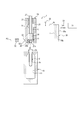
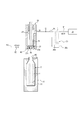
本発明の液体ブロー成形方法は、例えば図1に示す構成の液体ブロー成形装置1を用いて実施することができる。
図1に示す液体ブロー成形装置1は、合成樹脂製のプリフォーム2を液体ブロー成形して、内部に内容液を収容した液体入り容器に成形するものである。ここで、液体ブロー成形とは、プリフォーム2に供給する加圧媒体(加圧流体)として、エアブロー成形の際に用いられる加圧エアーに替えて加圧した液体を用いて行うブロー成形のことである。
プリフォーム2に供給される液体L、つまり成形後の液体入り容器に収容される内容液Lとしては、例えば飲料、化粧品、薬品、洗剤、シャンプー等のトイレタリーなどの様々な液体を用いることができる。
プリフォーム2としては、例えばポリプロピレン(PP)やポリエチレンテレフタレート(PET)等の熱可塑性を有する合成樹脂材料によって、開口端となる円筒状の口部2aと、口部2aに連なるとともに下端が閉塞された円筒状の胴部2bとを有する有底筒状に形成されたものを用いるのが好ましい。
なお、プリフォーム2としては、上記形状のものに限らず、口部2aを有していれば、成形後の容器の形状等に応じて種々の形状のものを用いることができる。
詳細は図示しないが、プリフォーム2の口部2aの外壁面には、成形後の液体入り容器の口部2aに閉塞キャップ(不図示)を打栓(アンダーカット係合)によって装着するための係合突起が設けられている。なお、口部2aの外壁面に係合突起に替えて雄ネジを設けて閉塞キャップを口部2aにねじ結合により装着する構成とすることもできる。
液体ブロー成形装置1は、ブロー成形用の金型10を有している。この金型10は、例えばボトル形状などの容器の最終形状に対応した形状のキャビティ11を有している。キャビティ11は金型10の上面において上方に向けて開口している。プリフォーム2は、胴部2bが金型10のキャビティ11の内部に配置されるとともに口部2aが金型10から上方に突出した状態となって金型10に装着される。
詳細は図示しないが、金型10は左右に型開きすることができ、プリフォーム2を液体入り容器に成形した後に金型10を左右に開くことで、当該液体入り容器を金型10から取り出すことができる。
金型10の上方には、プリフォーム2の内部に液体Lを供給するためのノズルユニット20が設けられている。ノズルユニット20は本体ブロック21を有し、この本体ブロック21は金型10に対して上下方向に相対移動自在となっている。本体ブロック21の下端には支持ブロック22が設けられ、この支持ブロック22により支持されて本体ブロック21の下端にはブローノズル23が装着されている。ブローノズル23は略円筒状に形成されており、ノズルユニット20が金型10に対して当該金型10に接近する方向のストローク端にまで相対移動したときに金型10に装着されたプリフォーム2の口部2aに上方側から密封状態で係合する。
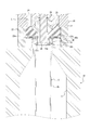
図2に示すように、ブローノズル23の円筒状部分の内側部分は液体供給口23aとなっている。また、ブローノズル23の液体供給口23aを構成する円筒状部分には、当該円筒状部分の下端に開口する排出口23bが設けられている。本実施の形態においては、ブローノズル23の当該円筒状部分には8つの排出口23bが周方向に等間隔に並べて設けられているが、その数は種々変更可能である。
図1に示すように、本体ブロック21の内部には上下方向に延びる供給路24が設けられている。この供給路24はブローノズル23の液体供給口23aに液体Lを供給するための流路であり、その下端においてブローノズル23の液体供給口23aに連通している。
さらに、本体ブロック21には、供給路24の上端に連通する供給ポート25が設けられている。
供給路24の内部にはブローノズル23の液体供給口23aを開閉するためのシール体26が配置されている。シール体26はノズルユニット20に対して上下方向に移動自在に設けられた軸体27の下端に固定され、供給路24の内部で上下方向に移動自在となっている。シール体26は円柱状に形成されており、下方側のストローク端位置である閉位置にまで移動したときに下端面においてブローノズル23の上面に当接してブローノズル23の液体供給口23aを閉塞する。一方、シール体26が閉位置から上方に向けて移動すると、ブローノズル23の液体供給口23aは開かれて供給路24と連通される。なお、シール体26は、軸体27と一体に形成するようにしてもよい。
図示するように、液体ブロー成形装置1は延伸ロッド28を備えた構成とすることもできる。延伸ロッド28は、軸体27の軸心に該軸体27に対して上下方向に相対移動自在に挿入されており、シール体26の軸心を貫通してシール体26の下端から出没可能に設けられている。延伸ロッド28は図示しない駆動源により駆動されて下方に向けて移動することにより、プリフォーム2を軸方向に延伸させることができる。このように、延伸ロッド28を設けた構成とした場合には、液体ブロー成形装置1は、プリフォーム2を延伸ロッド28により軸方向に延伸させつつ口部2aから供給される加圧した液体Lにより径方向に延伸させる二軸延伸ブロー成形を行うことができる。
なお、液体ブロー成形装置1は、延伸ロッド28を備えず、プリフォーム2を加圧した液体Lのみによって液体ブロー成形する構成とすることもできる。
供給ポート25には、配管P1によりポンプ30が接続されている。ポンプ30は、例えばシリンダ30aとピストン(プランジャー)30bとを備えたプランジャーポンプとして構成することができる。
ポンプ30には供給タンク31が接続されている。供給タンク31は、液体Lを収容するとともに当該液体Lを所定温度にまで加熱して当該温度に保持する構成とすることができる。ポンプ30と供給タンク31との間の流路には開閉弁V1が設けられ、この開閉弁V1により当該流路を開閉することができるようになっている。なお、符号32は配管P1に設けられた圧力計である。
図2に示すように、ブローノズル23に設けられた複数の排出口23bは、それぞれ上方に延びるとともに径方向外側に曲がる流路によってブローノズル23の外周面に環状に設けられた連結路23cに連通されている。連結路23cは、支持ブロック22の側面の接続ポート22aに接続されている。図1に示すように、接続ポート22aには配管P2が接続されており、当該配管P2を介して接続ポート22aは排出タンク(不図示)に接続されている。すなわち、ブローノズル23に設けられた複数の排出口23bは、それぞれ排出タンクに接続されている。なお、配管P2は、排出タンクに替えて排出用の吸引ポンプに接続することもできる。配管P2には、当該配管P2を開閉する開閉弁V2が設けられている。
ポンプ30は、シール体26が上方に移動して液体供給口23aが開かれ、開閉弁V1が閉じられた状態において正方向(加圧方向)に作動することにより、所定圧力にまで加圧した液体Lを配管P1、供給ポート25、供給路24及びブローノズル23の液体供給口23aを介してプリフォーム2の内部に供給することができる。また、ポンプ30は、シール体26によって液体供給口23aが閉じられ、開閉弁V1が開かれた状態において逆方向に作動することにより、供給タンク31に収容されている液体Lをシリンダ30aの内部に吸引し、次の液体ブロー成形に備えることができる。
液体ブロー成形装置1には、金型10に装着されているプリフォーム2を、その口部2aの軸心を中心として回転させるための回転駆動部40が設けられている。図2に示すように、本実施の形態では、回転駆動部40は、ブローノズル23の先端部の外周面に当該先端部に対して相対回転自在に設けられるとともにプリフォーム2の口部2aを内側から把持可能な把持部40aと、プリフォーム2の口部2aを挟んで把持部40aの径方向外側に配置されて把持部40aを回転駆動する駆動機構40bとを有している。駆動機構40bは電動モータ等の駆動源(不図示)からの駆動力を把持部40aに伝達することができる。このような構成の回転駆動部40は、把持部40aがプリフォーム2の口部2aを把持した状態で、駆動機構40bにより把持部40aを回転させることにより、プリフォーム2を把持部40aとともに口部2aの軸心を中心として回転させることができる。
なお、把持部40aは、プリフォーム2の口部2aの内面に液密に当接した状態で当該口部2aを把持して、プリフォーム2の口部2aからの液漏れを防止するシールとしても機能する。
また、回転駆動部40によるプリフォーム2の回転速度は、液体Lの種類や粘度等に応じて適宜設定される。
図示する場合では、回転駆動部40を、ブローノズル23の先端側部分に設けられてプリフォーム2の口部2aを把持する把持部40aを駆動機構40bによって回転させることでプリフォーム2をその口部2aの軸心を中心として回転させる構成としているが、これに限らず、プリフォーム2をその口部2aの軸心を中心として回転させることができれば、その構成は種々変更可能である。例えば、金型10の底部分からキャビティ11の内部に向けて突出する底ピンを設け、この底ピンによりプリフォーム2の底部分を把持し、当該底ピンを回転させることでプリフォーム2をその口部2aの軸心を中心として回転させる構成としてもよい。また、プリフォーム2の頚部分を金型10で保持した状態で金型10を回転させることで、金型10とともにプリフォーム2をその口部2aの軸心を中心として回転させる構成としてもよい。さらに、金型10とノズルユニット20の間に側方から挿通されたアーム部材の先端に設けた把持部でプリフォーム2の口部2aを把持し、当該アーム部材を回転させることでアーム部材とともにプリフォーム2をその口部2aの軸心を中心として回転させる構成としてもよい。
なお、回転駆動部40として、ブローノズル23の先端側部分に設けられてプリフォーム2の口部2aを把持する把持部40aを駆動機構40bによって回転させることでプリフォーム2をその口部2aの軸心を中心として回転させる構成、あるいは、金型10とノズルユニット20の間に側方から挿通されたアーム部材の先端に設けた把持部でプリフォーム2の口部2aを把持し、当該アーム部材を回転させることでアーム部材とともにプリフォーム2をその口部2aの軸心を中心として回転させる構成を採用した場合には、延伸されない口部2aを把持するため、プリフォーム2に変形を生じ難くすることができるので好ましい。
ノズルユニット20、シール体26、延伸ロッド28、ポンプ30、開閉弁V1、V2及び回転駆動部40等の作動は、図示しない制御装置によって統合的に制御される。この制御は、圧力計32の値等を参照して行うことができる。なお、開閉弁V1、V2は、制御装置によって制御可能な電磁弁により構成されるのが好ましい。
次に、このような構成の液体ブロー成形装置1を用いて、合成樹脂製のプリフォーム2から所定形状の容器の内部に液体(内容液)Lが収容されてなる液体入り容器Cを成形する方法(本実施の形態に係る液体ブロー成形方法)について説明する。
まず、図3に示すように、ノズルユニット20をブロー成形用の金型10に対して上方に離間させた状態において、予めヒーター等の加熱手段(不図示)を用いて延伸性を発現する程度の所定の温度(例えば80℃~150℃)にまで加熱しておいた合成樹脂製のプリフォーム2を金型10に装着し、型締めする。型締が完了すると、プリフォーム2は、口部2aが金型10の上面から上方に突出し、胴部2bがキャビティ11の内部に配置された状態となる。
プリフォーム2が金型10に装着されると、次に、ノズル係合工程が行われる。ノズル係合工程においては、ノズルユニット20を金型10に接近する方向に相対移動させ、ブローノズル23をプリフォーム2の口部2aに液密状態となるように係合させる。図1、図2は、ブローノズル23がプリフォーム2の口部2aに液密状態に係合したノズル係合工程の完了状態を示す。ノズル係合工程が完了すると、プリフォーム2の口部2aの内周面が回転駆動部40の把持部40aにより把持されるとともに液密にシールされる。なお、ノズル係合工程の完了状態においては、シール体26と開閉弁V1は閉じており、開閉弁V2は開かれている。また、延伸ロッド28はブローノズル23から下方に突出しない原位置に保持されている。
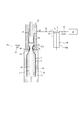
ノズル係合工程が完了すると、次に、気液置換工程が行われる。気液置換工程においては、図4に示すように、開閉弁V2すなわち排出口23bを開いた状態としたまま、シール体26を上方に移動させてブローノズル23の液体供給口23aを開き、その状態でポンプ30を正方向(加圧方向)に向けて作動させる。ポンプ30が作動すると、配管P1、供給ポート25、供給路24及びブローノズル23の液体供給口23aを通してプリフォーム2の内部に液体Lが供給される。
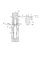
ここで、気液置換工程においては、ブローノズル23に設けられた排出口23bが開かれて排出タンクに連通された状態でプリフォーム2の内部に液体Lが供給されるので、プリフォーム2の内部に液体Lが供給されるにつれてプリフォーム2の内部の空気が排出口23bから排出タンクに向けて押し出されて排出され、プリフォーム2の内部は空気から液体Lに置換される。すなわち、気液置換工程を行うことにより、プリフォーム2の内部の空気を液体Lに置換して、図5に示すように、プリフォーム2を、ブロー成形される前の形状のままその内部が液体Lで満たされた状態とすることができる。
気液置換工程においては、後述するブロー成形工程よりも低い圧力でプリフォーム2の内部に所定量の液体Lを供給するのが好ましい。すなわち、気液置換工程においては、プリフォーム2が液体ブロー成形されない程度、または若干液体ブロー成形される程度の圧力で液体Lを供給するようにポンプ30の出力を調整して作動させるのがよい。
本発明の液体ブロー成形方法では、気液置換工程の完了後においてプリフォーム2の内部に残留する空気の量を低減させるために、プリフォーム2をブロー成形する前に、気液分離工程を行うようにしている。気液分離工程においては、回転駆動部40を作動させてプリフォーム2をその口部2aの軸心を中心として回転させ、プリフォーム2の内部の液体Lから空気を分離させる。プリフォーム2の内部の液体Lから空気を分離させることで、液体Lに混入していた空気をプリフォーム2の口部2aの側に移動させてブローノズル23に設けられた排出口23bから外部に効率良く排出させることができる。
本実施の形態においては、気液分離工程を、気液置換工程を行いつつ行うようにしている。すなわち、本実施の形態においては、図4、図5に示すように、回転駆動部40によりプリフォーム2をその口部2aの軸心を中心として回転させた状態で気液置換工程を行い、回転しているプリフォーム2の内部にブローノズル23の液体供給口23aを通して液体Lを供給する。プリフォーム2の内部に供給された液体Lは、プリフォーム2の回転による遠心力によってプリフォーム2の胴部2bの内面に向けて押し付けられつつ口部2aの側から底部の側に向けて螺旋状に流れることで空気と分離されつつプリフォーム2の底部の側に溜まる。一方、液体Lから分離された空気はプリフォーム2の上方に移動し、ブローノズル23に液体供給口23aとは別に設けられた排出口23bから排出される。このように、プリフォーム2をその口部2aの軸心を中心として回転させながら当該プリフォーム2の内部に液体Lを供給することで、液体Lに混入している空気を液体Lから分離させて排出口23bから外部に効率良く排出させつつプリフォーム2の内部を液体Lで満たすことができる。したがって、気液置換工程の完了後においてプリフォーム2の内部に残留する空気の量を低減させることができる。
特に、液体Lが、例えばシャンプーや液体洗剤のように比較的粘度が高い液体である場合には、プリフォーム2の内部に空気を含んだ液体Lが供給され、あるいはプリフォーム2の内部に供給された液体Lが当該プリフォーム2の内部の空気を巻き込んで空気を多く含んだ状態となる場合があるが、このような場合でも、気液分離工程を行うことにより、液体Lに混入している空気を液体Lから分離させて排出口23bから外部に効率良く排出させることができる。
本発明の液体ブロー成形方法では、気液分離工程を、気液置換工程の最中には行わずに気液置換工程の完了後に行う構成とすることもできる。この場合であっても、気液置換工程により内部が液体Lで満たされた状態となったプリフォーム2を、気液分離工程においてプリフォーム2をその口部2aの軸心を中心として回転させることによって液体Lに混入している空気を液体Lから分離させて排出口23bから外部に排出させることができる。したがって、気液置換工程の完了後においてプリフォーム2の内部に残留する空気の量を低減させることができる。
なお、気液分離工程は、気液置換工程の最中と気液置換工程の完了後の両期間に亘って連続して行うこともできる。
このように、本実施の形態の液体ブロー成形方法では、気液分離工程においてプリフォーム2をその口部2aの軸心を中心として回転させることで、プリフォーム2の内部の液体Lに混入している空気を液体Lから分離させて排出口23bから外部に効率良く排出させることができるので、気液置換工程の完了後においてプリフォーム2の内部に残留する空気の量を低減させることができる。
気液置換工程及び気液分離工程が完了すると、次に、ブロー成形工程が行われる。ブロー成形工程においては、図6に示すように、開閉弁V1、V2が閉じられ、回転駆動部40が停止し、シール体26により液体供給口23aが開かれた状態のまま、ポンプ30を正方向にさらに作動させる。このとき、ポンプ30は、プリフォーム2に供給する液体Lの圧力が当該プリフォーム2を液体ブロー成形することができる所定圧力となるような出力で作動する。このように、液体Lで満たされたプリフォーム2の内部に、さらに所定圧力にまで加圧した液体Lを供給することにより、プリフォーム2は液体Lの圧力により膨張状に延伸される。そして、図6に示すように、プリフォーム2がキャビティ11の内面に沿った所定形状の液体入り容器Cとなるまで成形(液体ブロー成形)されると、ポンプ30の作動が停止され、ブロー成形工程が完了する。
ここで、上記の通り、気液置換工程においてプリフォーム2の内部の空気を液体Lに置換し、また、気液分離工程を行うことで当該プリフォーム2の内部に残留する空気の量をさらに低減させるようにしているので、ブロー成形工程においてプリフォーム2の内部に供給される液体Lに空気が巻き込まれてプリフォーム2の内部で液体Lに泡立ち等が生じることを抑制して、成形条件を安定化させ、また、容器の成形性を高めることができる。よって、液体入り容器Cを、所定の内容量及び形状を有するように、精度よく且つ低コストで製造することができる。
液体ブロー成形装置1に延伸ロッド28を設けた場合には、ブロー成形工程において延伸ロッド28をプリフォーム2の内部に向けて進出移動させ、延伸ロッド28によりプリフォーム2を軸方向(縦方向)へ延伸させる。これにより、プリフォーム2を液体Lの圧力と延伸ロッド28とで二軸方向に延伸する二軸延伸ブロー成形を行うことができる。二軸延伸ブロー成形によれば、プリフォーム2をより精度よく所定形状の液体入り容器Cに成形することができる。
本実施の形態においては、ブロー成形工程が完了した後に、サックバック工程を行うようにしている。
図7に示すように、サックバック工程においては、シール体26を開位置としてブローノズル23の液体供給口23aを開いた状態としたままポンプ30を逆方向に作動させ、ブロー成形工程で所定形状に成形された液体入り容器Cの内部から液体供給口23aを通して供給路24に所定量の液体Lを吸い戻す(サックバックする)。サックバック工程において供給路24に吸い戻す液体Lの量は、完成後の液体入り容器Cの内部に設けられるヘッドスペースHSが所定量となるように適宜設定される。サックバック工程が行われると、液体入り容器Cは、供給路24に吸い戻された液体Lの量だけその内容量が減少し、キャビティ11との間に隙間を生じた減容変形状態となり、その内部は大気圧よりも低い負圧状態となる。
このとき、気液置換工程においてプリフォーム2の内部の空気を液体Lに置換し、また、気液分離工程を行うことで当該プリフォーム2の内部に残留する空気の量をさらに低減させるようにしているので、サックバックにより液体入り容器Cから供給路24の内部に液体Lを引き戻すようにしても、供給路24の内部の液体Lに多くの空気が混入することがなく、次に行う液体ブロー成形工程において成形性の悪化等は生じない。
サックバック工程が完了すると、次に、サックバック工程において所定形状に成形された液体入り容器Cの内部から供給路24に所定量の液体Lを吸い戻した状態のままシール体26によりブローノズル23の液体供給口23aを閉塞した後、図8に示すように、ノズルユニット20を金型10から離れる方向に相対移動させ、ブローノズル23をプリフォーム2の口部2aから離脱させ、ブローノズル23の口部2aとの係合を解除する。成形後の液体入り容器Cの口部2aからブローノズル23が離脱すると、サックバック工程において減容変形状態となっていた液体入り容器Cが元の形状に復元し、液体入り容器Cの内部には所定量の液体Lの上部に所定量のヘッドスペースHSが形成される。なお、ブローノズル23を離脱させる前に開閉弁V2を開放することにより外気と連通させて、サックバック工程において減容変形状態となっていた液体入り容器Cを元の形状に復元させてヘッドスペースHSを形成するようにしてもよい。
そして、その状態で図示しない閉栓装置により口部2aにキャップが装着され、次いで金型10が開かれて完成した液体入り容器Cが金型10から取り出される。なお、液体入り容器Cを金型10から取り出した後にキャップを装着してもよい。
液体ブロー成形装置1に延伸ロッド28を設けた場合には、シール体26によりブローノズル23の液体供給口23aを閉塞した後に、液体入り容器Cから延伸ロッド28を引き抜くようにすればよい。これにより、液体ブロー成形装置1に延伸ロッド28を設けない場合に比べて、延伸ロッド28の体積分だけさらにヘッドスペースHSの量を増加させることができる。この場合、サックバック工程において液体入り容器Cの内部から供給路24に吸い戻す液体Lの量は、液体入り容器Cの内部に挿入される延伸ロッド28の体積を勘案して設定すればよい。
以上の通り、本実施の形態の液体ブロー成形方法では、気液置換工程においてプリフォーム2の内部の空気を液体Lに置換し、また、気液分離工程を行うことで当該プリフォーム2の内部に残留する空気の量をさらに低減させるようにしているので、ブロー成形工程においてプリフォーム2の内部に供給される液体Lに空気が巻き込まれてプリフォーム2の内部で液体Lに泡立ち等が生じることを抑制して、液体入り容器Cを、所定の内容量及び形状を有するように、精度よく且つ低コストで製造することができる。
このとき、気液置換工程においては、液体ブロー成形工程よりも低い圧力でプリフォーム2の内部に所定量の液体Lを供給するようにしたので、液体Lに泡立ち等を生じさせることなくプリフォーム2の内部の空気を液体Lに置換することができる。
また、本実施の形態の液体ブロー成形方法では、気液置換工程を行いつつ気液分離工程をも行うようにしたので、気液置換工程によってプリフォーム2の内部に供給された液体Lが、気液分離工程によって回転されているプリフォーム2の遠心力によってプリフォーム2の胴部2bの内面に向けて押し付けられつつ口部2aの側から底部の側に向けて螺旋状に流れるようにして、プリフォーム2に供給される液体Lから空気を効率良く分離させることができる。これにより、プリフォーム2の内部に残留する空気の量をさらに低減させることができる。
さらに、気液置換工程の完了後に気液分離工程を行うようにした場合には、プリフォーム2の底部の側にある空気も確実に液体Lから分離されるようにして、プリフォーム2の内部に残留する空気の量をさらに低減させることができる。
さらに、本実施の形態の液体ブロー成形方法では、気液分離工程において、ブローノズル23に設けた把持部40aによりプリフォーム2を把持して把持部40aとともにプリフォーム2を回転させるようにしたので、プリフォーム2に変形を生じさせることなく当該プリフォーム2を確実に回転させることができる。これにより、プリフォーム2からより精度よく液体入り容器Cを成形することができる。
さらに、本実施の形態の液体ブロー成形方法では、気液置換工程の前に、ブローノズル23を口部2aに係合させるノズル係合工程を有し、気液置換工程において、ブローノズル23の液体供給口23aを通して口部2aからプリフォーム2の内部に液体Lを供給しつつ、液体供給口23aとは別にブローノズル23に設けられた排出口23bからプリフォーム2の内部の空気を外部に排出させるようにしたので、液体Lを外部に漏れ出させることなくプリフォーム2の内部の空気を外部に排出させることができる。
本発明は前記実施の形態に限定されるものではなく、その要旨を逸脱しない範囲で種々変更可能であることはいうまでもない。
例えば、前記実施の形態では、図1に示す構成の液体ブロー成形装置1を用いて本発明の液体ブロー成形方法を行う場合を示したが、他の構成の液体ブロー成形装置等を用いて本発明の液体ブロー成形方法を行うこともできる。
また、前記実施の形態では、気液置換工程においてプリフォーム2の内部の空気を外部に排出するための排出口23bをブローノズル23に設けるようにしているが、例えば延伸ロッド28などの他の部位に設けるようにしてもよい。
さらに、前記実施の形態では、気液分離工程において、ブローノズル23の先端側部分に設けられた把持部40aでプリフォーム2の口部2aを把持し、把持部40aを駆動機構40bによって回転させることでプリフォーム2をその口部2aの軸心を中心として回転させるようにしているが、これに限らず、プリフォーム2をその口部2aの軸心を中心として回転させることができれば、例えば、金型10の底部分からキャビティ11の内部に向けて突出する底ピンによりプリフォーム2の底部分を把持し、当該底ピンを回転させることでプリフォーム2をその口部2aの軸心を中心として回転させるようにし、または、プリフォーム2の頚部分を金型10で保持した状態で金型10を回転させることで、金型10とともにプリフォーム2をその口部2aの軸心を中心として回転させるようにし、あるいは、金型10とノズルユニット20の間に側方から挿通されたアーム部材の先端に設けた把持部でプリフォーム2の口部2aを把持し、当該アーム部材(把持部)を回転させることでアーム部材とともにプリフォーム2をその口部2aの軸心を中心として回転させる構成とするなど、その構成は種々変更可能である。
また、回転駆動部40によるプリフォーム2の回転速度や回転方向は種々変更可能である。
さらに、前記実施の形態では、気液置換工程において、プリフォーム2の内部の空気をブローノズル23に設けた排出口23bから外部に排出するようにしているが、これに限らず、気液置換工程の前に、口部2aを密封しない第1位置にまでブローノズル23を下降させ(第1ノズル下降工程)、気液置換工程において、第1位置にあるブローノズル23を通して口部2aからプリフォーム2の内部に液体Lを供給しつつ、ブローノズル23と口部2aとの隙間からプリフォーム2の内部の空気を外部に排出させるようにしてもよい。この場合、気液置換工程の後に、口部2aを密封する第2位置にまでブローノズル23を下降させ(第2ノズル下降工程)、その後にブロー成形工程が行なわれる。このような構成により、ブローノズル23に排出口23bを設けることを不要として液体ブロー成形装置1の構成を簡素化し、液体ブロー成形方法で成形される液体入り容器Cの製造コストを低減することができる。
なお、上記構成においては、例えば、予め回転駆動部40をプリフォーム2の口部2aに液密に嵌合させた状態としておき、ブローノズル23を第1位置にまで下降させたときにブローノズル23と回転駆動部40との隙間からプリフォーム2の内部の空気を外部に排出させ、その後、ブローノズル23を第2位置にまで下降させたときにブローノズル23と回転駆動部40との間の隙間が閉塞される構成とし、あるいは、ブローノズル23を第1位置にまで下降させたときに回転駆動部40をプリフォーム2の口部2aに液密に嵌合させるとともに回転駆動部40に設けた排出路からプリフォーム2の内部の空気を外部に排出させ、その後、ブローノズル23を第2位置にまで下降させたときに回転駆動部40の排気路が閉塞される構成とするなど、ブローノズル23ないし回転駆動部40の構成は種々変更可能である。
さらに、前記実施の形態では、ブロー成形工程において延伸ロッド28を用いて二軸延伸ブロー成形を行うとともに、液体入り容器Cから延伸ロッド28を引き抜くことでヘッドスペースHSを増加させるようにしているが、延伸ロッド28によるヘッドスペースHSの形成を行わない(例えば、ブロー成形工程の終了前に延伸ロッド28を引き抜く)構成とすることもできる。
さらに、前記実施の形態においては、ポンプ30はプランジャーポンプとされているが、これに限らず、液体Lを所定の圧力にまで加圧してプリフォーム2に供給することができるとともに成形後の液体入り容器Cの内部から所定量の液体Lを吸い戻すことができるものであれば種々の構成のポンプを用いることができる。
さらに、本発明の液体ブロー成形方法は、シャンプーや液体洗剤等の比較的粘度の高い内容液を収容するポンプ付き容器に用いられる液体入り容器Cのように、その内部に大きなヘッドスペースHSを要するものを成形する場合に適用するのが好ましいが、ヘッドスペースHSの大小に拘わらず種々の液体入り容器Cの成形に適用することもできる。
さらに、気液分離工程をブロー成形工程の最中やブロー成形工程の後に行うようにしてもよいが、ブロー成形工程は原則的にプリフォーム2を密封した状態で行うものであるので、液体Lから分離した空気を外部に除去することは困難である。よって、気液分離工程は、気液置換工程とともに、あるいは気液置換工程の後であってブロー成形工程の前に行うのが好ましい。
1 液体ブロー成形装置
2 プリフォーム
2a 口部
2b 胴部
10 金型
11 キャビティ
20 ノズルユニット
21 本体ブロック
22 支持ブロック
22a 接続ポート
23 ブローノズル
23a 液体供給口
23b 排出口
23c 連結路
24 供給路
25 供給ポート
26 シール体
27 軸体
28 延伸ロッド
30 ポンプ
30a シリンダ
30b ピストン
31 供給タンク
40 回転駆動部
40a 把持部
40b 駆動機構
P1 配管
V1 開閉弁
P2 配管
V2 開閉弁
C 液体入り容器
2 プリフォーム
2a 口部
2b 胴部
10 金型
11 キャビティ
20 ノズルユニット
21 本体ブロック
22 支持ブロック
22a 接続ポート
23 ブローノズル
23a 液体供給口
23b 排出口
23c 連結路
24 供給路
25 供給ポート
26 シール体
27 軸体
28 延伸ロッド
30 ポンプ
30a シリンダ
30b ピストン
31 供給タンク
40 回転駆動部
40a 把持部
40b 駆動機構
P1 配管
V1 開閉弁
P2 配管
V2 開閉弁
C 液体入り容器
Claims (7)
- 口部を有する合成樹脂製のプリフォームを所定形状の液体入り容器に成形する液体ブロー成形方法であって、
ブローノズルを通して前記口部から前記プリフォームの内部に液体を供給しつつ該プリフォームの内部の空気を外部に排出させる気液置換工程と、
前記口部の軸心を中心として前記プリフォームを回転させて該プリフォームの内部の液体から空気を分離させる気液分離工程と、
前記気液分離工程の後、前記ブローノズルを通して前記口部から前記プリフォームの内部に加圧した液体を供給して該プリフォームを所定形状の容器に成形するブロー成形工程と、を有することを特徴とする液体ブロー成形方法。 - 前記気液置換工程を行いつつ前記気液分離工程をも行う、請求項1に記載の液体ブロー成形方法。
- 前記気液置換工程の完了後に前記気液分離工程を行う、請求項1に記載の液体ブロー成形方法。
- 前記気液分離工程において、前記ブローノズルに設けた把持部により前記プリフォームを把持して該把持部とともに前記プリフォームを回転させる、請求項1~3の何れか1項に記載の液体ブロー成形方法。
- 前記気液置換工程の前に、前記ブローノズルを前記口部に係合させるノズル係合工程を有し、
前記気液置換工程において、前記ブローノズルの液体供給口を通して前記口部から前記プリフォームの内部に液体を供給しつつ、前記液体供給口とは別に前記ブローノズルに設けられた排出口から前記プリフォームの内部の空気を外部に排出させる、請求項1~4の何れか1項に記載の液体ブロー成形方法。 - 前記気液置換工程の前に、前記口部を密封しない第1位置にまで前記ブローノズルを下降させる第1ノズル下降工程を有し、
前記気液置換工程において、前記第1位置にある前記ブローノズルを通して前記口部から前記プリフォームの内部に液体を供給しつつ、前記ブローノズルと前記口部との隙間から前記プリフォームの内部の空気を外部に排出させ、
前記気液置換工程の後に、前記口部を密封する第2位置にまで前記ブローノズルを下降させる第2ノズル下降工程を有し、
前記第2ノズル下降工程の後に前記ブロー成形工程を行う、請求項1~4の何れか1項に記載の液体ブロー成形方法。 - 前記ブロー成形工程の後、前記ブローノズルを通して成形後の前記容器の内部から所定量の液体を吸い戻すサックバック工程を有する、請求項1~6の何れか1項に記載の液体ブロー成形方法。
Priority Applications (3)
| Application Number | Priority Date | Filing Date | Title |
|---|---|---|---|
| CN201880075277.7A CN111372751A (zh) | 2017-11-30 | 2018-10-03 | 液体吹塑成型方法 |
| EP18883542.5A EP3718740B1 (en) | 2017-11-30 | 2018-10-03 | Liquid blow molding method |
| US16/765,566 US10940632B2 (en) | 2017-11-30 | 2018-10-03 | Liquid blow molding method |
Applications Claiming Priority (2)
| Application Number | Priority Date | Filing Date | Title |
|---|---|---|---|
| JP2017230492A JP6893861B2 (ja) | 2017-11-30 | 2017-11-30 | 液体ブロー成形方法 |
| JP2017-230492 | 2017-11-30 |
Publications (1)
| Publication Number | Publication Date |
|---|---|
| WO2019106955A1 true WO2019106955A1 (ja) | 2019-06-06 |
Family
ID=66665652
Family Applications (1)
| Application Number | Title | Priority Date | Filing Date |
|---|---|---|---|
| PCT/JP2018/037104 Ceased WO2019106955A1 (ja) | 2017-11-30 | 2018-10-03 | 液体ブロー成形方法 |
Country Status (5)
| Country | Link |
|---|---|
| US (1) | US10940632B2 (ja) |
| EP (1) | EP3718740B1 (ja) |
| JP (1) | JP6893861B2 (ja) |
| CN (1) | CN111372751A (ja) |
| WO (1) | WO2019106955A1 (ja) |
Families Citing this family (3)
| Publication number | Priority date | Publication date | Assignee | Title |
|---|---|---|---|---|
| JP7184462B2 (ja) * | 2019-01-31 | 2022-12-06 | 株式会社吉野工業所 | 内容液入りボトルの製造方法 |
| DE102019114953A1 (de) * | 2019-06-04 | 2020-12-10 | Khs Corpoplast Gmbh | Verfahren und Vorrichtung zum Herstellen von mit flüssigem Füllgut befüllten Behältern aus thermisch konditionierten Vorformlingen |
| CN112694241A (zh) * | 2021-02-26 | 2021-04-23 | 深圳市应有仁建材有限公司 | 一种根据吹气量来调整气泵进气的玻璃吹管装置 |
Citations (7)
| Publication number | Priority date | Publication date | Assignee | Title |
|---|---|---|---|---|
| JPS586929B2 (ja) | 1975-06-10 | 1983-02-07 | アサヒコウガクコウギヨウ カブシキガイシヤ | ジドウロコウセイギヨカメラニオケル ハツシンシユウキガジカンノシスウデヘンカスルハツシンキ |
| JP2000043129A (ja) * | 1998-07-29 | 2000-02-15 | Ishikawajima Harima Heavy Ind Co Ltd | プラスチック容器の成形方法 |
| JP2015506288A (ja) * | 2011-12-21 | 2015-03-02 | アムコー リミテッド | 成形装置のシールシステム |
| JP2016537227A (ja) * | 2013-10-21 | 2016-12-01 | ディスクマ アクチェンゲゼルシャフト | 共通部分を有する第1閉ループ及び第2閉ループを備えた、容器を形成かつ充填する装置 |
| JP2016210037A (ja) * | 2015-04-30 | 2016-12-15 | 株式会社吉野工業所 | 液体ブロー成形装置 |
| WO2018079012A1 (ja) * | 2016-10-28 | 2018-05-03 | 株式会社吉野工業所 | 液体ブロー成形方法 |
| WO2018198449A1 (ja) * | 2017-04-27 | 2018-11-01 | 株式会社吉野工業所 | 液体入り容器の製造方法 |
Family Cites Families (12)
| Publication number | Priority date | Publication date | Assignee | Title |
|---|---|---|---|---|
| JPH01132369A (ja) * | 1987-11-18 | 1989-05-24 | Asahi Breweries Ltd | 発泡飲料のガス抜き方法 |
| FR2804059B1 (fr) * | 2000-01-20 | 2002-08-30 | Sidel Sa | Machine de soufflage de recipients comportant des moyens d'orientation des preformes dans le moule de soufflage |
| FR2962930B1 (fr) * | 2010-07-20 | 2012-08-31 | Sidel Participations | Procede de formage d'un recipient par soufflage et remplissage |
| JP5806929B2 (ja) | 2011-12-27 | 2015-11-10 | 株式会社吉野工業所 | ブロー成形装置およびブロー成形容器の製造方法 |
| JP5870001B2 (ja) * | 2012-09-28 | 2016-02-24 | 株式会社吉野工業所 | ブロー成形装置及び容器の製造方法 |
| EP2988918B1 (en) * | 2013-04-24 | 2016-11-16 | Discma AG | Method and machine for manufacturing plastic containers |
| JP6100137B2 (ja) * | 2013-09-30 | 2017-03-22 | 株式会社吉野工業所 | ブロー成形装置 |
| EP2860016B1 (en) * | 2013-10-10 | 2017-03-01 | Discma AG | Method of delivering a liquid volume and associated apparatus |
| EP2930005B1 (en) * | 2014-04-08 | 2017-06-07 | Discma AG | Rotary machine and method for hydraulic forming of shaped containers |
| DE102014016140A1 (de) * | 2014-10-30 | 2016-05-04 | Khs Corpoplast Gmbh | Verfahren zur Entfernung von Luft aus Vorformlingen zur Herstellung von gefüllten Behältern aus Kunststoff |
| EP3109029B1 (en) * | 2015-06-25 | 2017-12-13 | Discma AG | Forming station for forming a container from a preform comprising a vibratory stretch rod, method for forming a container using said forming station, method for suppressing foam from the neck of a container using said forming station and method for cleaning a forming station. |
| JP6594823B2 (ja) * | 2016-04-28 | 2019-10-23 | 株式会社吉野工業所 | 液体ブロー成形方法 |
-
2017
- 2017-11-30 JP JP2017230492A patent/JP6893861B2/ja active Active
-
2018
- 2018-10-03 WO PCT/JP2018/037104 patent/WO2019106955A1/ja not_active Ceased
- 2018-10-03 EP EP18883542.5A patent/EP3718740B1/en active Active
- 2018-10-03 US US16/765,566 patent/US10940632B2/en active Active
- 2018-10-03 CN CN201880075277.7A patent/CN111372751A/zh active Pending
Patent Citations (7)
| Publication number | Priority date | Publication date | Assignee | Title |
|---|---|---|---|---|
| JPS586929B2 (ja) | 1975-06-10 | 1983-02-07 | アサヒコウガクコウギヨウ カブシキガイシヤ | ジドウロコウセイギヨカメラニオケル ハツシンシユウキガジカンノシスウデヘンカスルハツシンキ |
| JP2000043129A (ja) * | 1998-07-29 | 2000-02-15 | Ishikawajima Harima Heavy Ind Co Ltd | プラスチック容器の成形方法 |
| JP2015506288A (ja) * | 2011-12-21 | 2015-03-02 | アムコー リミテッド | 成形装置のシールシステム |
| JP2016537227A (ja) * | 2013-10-21 | 2016-12-01 | ディスクマ アクチェンゲゼルシャフト | 共通部分を有する第1閉ループ及び第2閉ループを備えた、容器を形成かつ充填する装置 |
| JP2016210037A (ja) * | 2015-04-30 | 2016-12-15 | 株式会社吉野工業所 | 液体ブロー成形装置 |
| WO2018079012A1 (ja) * | 2016-10-28 | 2018-05-03 | 株式会社吉野工業所 | 液体ブロー成形方法 |
| WO2018198449A1 (ja) * | 2017-04-27 | 2018-11-01 | 株式会社吉野工業所 | 液体入り容器の製造方法 |
Non-Patent Citations (1)
| Title |
|---|
| See also references of EP3718740A4 |
Also Published As
| Publication number | Publication date |
|---|---|
| US20200307062A1 (en) | 2020-10-01 |
| EP3718740A4 (en) | 2021-08-11 |
| JP2019098594A (ja) | 2019-06-24 |
| EP3718740B1 (en) | 2022-04-27 |
| CN111372751A (zh) | 2020-07-03 |
| JP6893861B2 (ja) | 2021-06-23 |
| US10940632B2 (en) | 2021-03-09 |
| EP3718740A1 (en) | 2020-10-07 |
Similar Documents
| Publication | Publication Date | Title |
|---|---|---|
| JP6594823B2 (ja) | 液体ブロー成形方法 | |
| JP6632872B2 (ja) | 液体ブロー成形方法 | |
| US11400637B2 (en) | Liquid blow molding method | |
| JP2018183973A (ja) | 液体入り容器の製造方法 | |
| EP3663071A1 (en) | Device and method for manufacturing container filled with liquid | |
| WO2019106955A1 (ja) | 液体ブロー成形方法 | |
| WO2019003698A1 (ja) | 液体入り容器の製造方法 | |
| US11504897B2 (en) | Liquid container manufacturing method | |
| WO2018179747A1 (ja) | 容器製造方法 | |
| CN110545983B (zh) | 装有液体的容器的制造方法 | |
| EP3718738B1 (en) | Liquid blow molding method | |
| JP7710408B2 (ja) | 液体ブロー成形方法 | |
| CN111655446A (zh) | 液体吹塑成型装置 |
Legal Events
| Date | Code | Title | Description |
|---|---|---|---|
| 121 | Ep: the epo has been informed by wipo that ep was designated in this application |
Ref document number: 18883542 Country of ref document: EP Kind code of ref document: A1 |
|
| NENP | Non-entry into the national phase |
Ref country code: DE |
|
| ENP | Entry into the national phase |
Ref document number: 2018883542 Country of ref document: EP Effective date: 20200630 |