WO2019106955A1 - Procédé de moulage par soufflage de liquide - Google Patents
Procédé de moulage par soufflage de liquide Download PDFInfo
- Publication number
- WO2019106955A1 WO2019106955A1 PCT/JP2018/037104 JP2018037104W WO2019106955A1 WO 2019106955 A1 WO2019106955 A1 WO 2019106955A1 JP 2018037104 W JP2018037104 W JP 2018037104W WO 2019106955 A1 WO2019106955 A1 WO 2019106955A1
- Authority
- WO
- WIPO (PCT)
- Prior art keywords
- liquid
- preform
- gas
- blow molding
- nozzle
- Prior art date
- Legal status (The legal status is an assumption and is not a legal conclusion. Google has not performed a legal analysis and makes no representation as to the accuracy of the status listed.)
- Ceased
Links
Images



Classifications
-
- B—PERFORMING OPERATIONS; TRANSPORTING
- B29—WORKING OF PLASTICS; WORKING OF SUBSTANCES IN A PLASTIC STATE IN GENERAL
- B29C—SHAPING OR JOINING OF PLASTICS; SHAPING OF MATERIAL IN A PLASTIC STATE, NOT OTHERWISE PROVIDED FOR; AFTER-TREATMENT OF THE SHAPED PRODUCTS, e.g. REPAIRING
- B29C49/00—Blow-moulding, i.e. blowing a preform or parison to a desired shape within a mould; Apparatus therefor
- B29C49/42—Component parts, details or accessories; Auxiliary operations
- B29C49/46—Component parts, details or accessories; Auxiliary operations characterised by using particular environment or blow fluids other than air
-
- B—PERFORMING OPERATIONS; TRANSPORTING
- B29—WORKING OF PLASTICS; WORKING OF SUBSTANCES IN A PLASTIC STATE IN GENERAL
- B29C—SHAPING OR JOINING OF PLASTICS; SHAPING OF MATERIAL IN A PLASTIC STATE, NOT OTHERWISE PROVIDED FOR; AFTER-TREATMENT OF THE SHAPED PRODUCTS, e.g. REPAIRING
- B29C49/00—Blow-moulding, i.e. blowing a preform or parison to a desired shape within a mould; Apparatus therefor
- B29C49/08—Biaxial stretching during blow-moulding
- B29C49/10—Biaxial stretching during blow-moulding using mechanical means for prestretching
- B29C49/122—Drive means therefor
-
- B—PERFORMING OPERATIONS; TRANSPORTING
- B29—WORKING OF PLASTICS; WORKING OF SUBSTANCES IN A PLASTIC STATE IN GENERAL
- B29C—SHAPING OR JOINING OF PLASTICS; SHAPING OF MATERIAL IN A PLASTIC STATE, NOT OTHERWISE PROVIDED FOR; AFTER-TREATMENT OF THE SHAPED PRODUCTS, e.g. REPAIRING
- B29C49/00—Blow-moulding, i.e. blowing a preform or parison to a desired shape within a mould; Apparatus therefor
- B29C49/42—Component parts, details or accessories; Auxiliary operations
- B29C49/58—Blowing means
-
- B—PERFORMING OPERATIONS; TRANSPORTING
- B65—CONVEYING; PACKING; STORING; HANDLING THIN OR FILAMENTARY MATERIAL
- B65B—MACHINES, APPARATUS OR DEVICES FOR, OR METHODS OF, PACKAGING ARTICLES OR MATERIALS; UNPACKING
- B65B3/00—Packaging plastic material, semiliquids, liquids or mixed solids and liquids, in individual containers or receptacles, e.g. bags, sacks, boxes, cartons, cans, or jars
- B65B3/02—Machines characterised by the incorporation of means for making the containers or receptacles
- B65B3/022—Making containers by moulding of a thermoplastic material
-
- B—PERFORMING OPERATIONS; TRANSPORTING
- B65—CONVEYING; PACKING; STORING; HANDLING THIN OR FILAMENTARY MATERIAL
- B65B—MACHINES, APPARATUS OR DEVICES FOR, OR METHODS OF, PACKAGING ARTICLES OR MATERIALS; UNPACKING
- B65B3/00—Packaging plastic material, semiliquids, liquids or mixed solids and liquids, in individual containers or receptacles, e.g. bags, sacks, boxes, cartons, cans, or jars
- B65B3/18—Controlling escape of air from containers or receptacles during filling
-
- B—PERFORMING OPERATIONS; TRANSPORTING
- B29—WORKING OF PLASTICS; WORKING OF SUBSTANCES IN A PLASTIC STATE IN GENERAL
- B29C—SHAPING OR JOINING OF PLASTICS; SHAPING OF MATERIAL IN A PLASTIC STATE, NOT OTHERWISE PROVIDED FOR; AFTER-TREATMENT OF THE SHAPED PRODUCTS, e.g. REPAIRING
- B29C49/00—Blow-moulding, i.e. blowing a preform or parison to a desired shape within a mould; Apparatus therefor
- B29C49/42—Component parts, details or accessories; Auxiliary operations
- B29C2049/4294—Sealing means
-
- B—PERFORMING OPERATIONS; TRANSPORTING
- B29—WORKING OF PLASTICS; WORKING OF SUBSTANCES IN A PLASTIC STATE IN GENERAL
- B29C—SHAPING OR JOINING OF PLASTICS; SHAPING OF MATERIAL IN A PLASTIC STATE, NOT OTHERWISE PROVIDED FOR; AFTER-TREATMENT OF THE SHAPED PRODUCTS, e.g. REPAIRING
- B29C49/00—Blow-moulding, i.e. blowing a preform or parison to a desired shape within a mould; Apparatus therefor
- B29C49/42—Component parts, details or accessories; Auxiliary operations
- B29C49/46—Component parts, details or accessories; Auxiliary operations characterised by using particular environment or blow fluids other than air
- B29C2049/4602—Blowing fluids
- B29C2049/465—Blowing fluids being incompressible
- B29C2049/4664—Blowing fluids being incompressible staying in the final article
-
- B—PERFORMING OPERATIONS; TRANSPORTING
- B29—WORKING OF PLASTICS; WORKING OF SUBSTANCES IN A PLASTIC STATE IN GENERAL
- B29C—SHAPING OR JOINING OF PLASTICS; SHAPING OF MATERIAL IN A PLASTIC STATE, NOT OTHERWISE PROVIDED FOR; AFTER-TREATMENT OF THE SHAPED PRODUCTS, e.g. REPAIRING
- B29C49/00—Blow-moulding, i.e. blowing a preform or parison to a desired shape within a mould; Apparatus therefor
- B29C49/42—Component parts, details or accessories; Auxiliary operations
- B29C49/58—Blowing means
- B29C2049/5862—Drive means therefore
-
- B—PERFORMING OPERATIONS; TRANSPORTING
- B29—WORKING OF PLASTICS; WORKING OF SUBSTANCES IN A PLASTIC STATE IN GENERAL
- B29C—SHAPING OR JOINING OF PLASTICS; SHAPING OF MATERIAL IN A PLASTIC STATE, NOT OTHERWISE PROVIDED FOR; AFTER-TREATMENT OF THE SHAPED PRODUCTS, e.g. REPAIRING
- B29C49/00—Blow-moulding, i.e. blowing a preform or parison to a desired shape within a mould; Apparatus therefor
- B29C49/42—Component parts, details or accessories; Auxiliary operations
- B29C49/58—Blowing means
- B29C2049/5893—Mounting, exchanging or centering blowing means
-
- B—PERFORMING OPERATIONS; TRANSPORTING
- B29—WORKING OF PLASTICS; WORKING OF SUBSTANCES IN A PLASTIC STATE IN GENERAL
- B29C—SHAPING OR JOINING OF PLASTICS; SHAPING OF MATERIAL IN A PLASTIC STATE, NOT OTHERWISE PROVIDED FOR; AFTER-TREATMENT OF THE SHAPED PRODUCTS, e.g. REPAIRING
- B29C2949/00—Indexing scheme relating to blow-moulding
- B29C2949/07—Preforms or parisons characterised by their configuration
- B29C2949/0715—Preforms or parisons characterised by their configuration the preform having one end closed
-
- B—PERFORMING OPERATIONS; TRANSPORTING
- B29—WORKING OF PLASTICS; WORKING OF SUBSTANCES IN A PLASTIC STATE IN GENERAL
- B29C—SHAPING OR JOINING OF PLASTICS; SHAPING OF MATERIAL IN A PLASTIC STATE, NOT OTHERWISE PROVIDED FOR; AFTER-TREATMENT OF THE SHAPED PRODUCTS, e.g. REPAIRING
- B29C49/00—Blow-moulding, i.e. blowing a preform or parison to a desired shape within a mould; Apparatus therefor
- B29C49/02—Combined blow-moulding and manufacture of the preform or the parison
- B29C49/06—Injection blow-moulding
-
- B—PERFORMING OPERATIONS; TRANSPORTING
- B29—WORKING OF PLASTICS; WORKING OF SUBSTANCES IN A PLASTIC STATE IN GENERAL
- B29C—SHAPING OR JOINING OF PLASTICS; SHAPING OF MATERIAL IN A PLASTIC STATE, NOT OTHERWISE PROVIDED FOR; AFTER-TREATMENT OF THE SHAPED PRODUCTS, e.g. REPAIRING
- B29C49/00—Blow-moulding, i.e. blowing a preform or parison to a desired shape within a mould; Apparatus therefor
- B29C49/42—Component parts, details or accessories; Auxiliary operations
- B29C49/4289—Valve constructions or configurations, e.g. arranged to reduce blowing fluid consumption
-
- B—PERFORMING OPERATIONS; TRANSPORTING
- B29—WORKING OF PLASTICS; WORKING OF SUBSTANCES IN A PLASTIC STATE IN GENERAL
- B29K—INDEXING SCHEME ASSOCIATED WITH SUBCLASSES B29B, B29C OR B29D, RELATING TO MOULDING MATERIALS OR TO MATERIALS FOR MOULDS, REINFORCEMENTS, FILLERS OR PREFORMED PARTS, e.g. INSERTS
- B29K2023/00—Use of polyalkenes or derivatives thereof as moulding material
- B29K2023/04—Polymers of ethylene
- B29K2023/06—PE, i.e. polyethylene
-
- B—PERFORMING OPERATIONS; TRANSPORTING
- B29—WORKING OF PLASTICS; WORKING OF SUBSTANCES IN A PLASTIC STATE IN GENERAL
- B29K—INDEXING SCHEME ASSOCIATED WITH SUBCLASSES B29B, B29C OR B29D, RELATING TO MOULDING MATERIALS OR TO MATERIALS FOR MOULDS, REINFORCEMENTS, FILLERS OR PREFORMED PARTS, e.g. INSERTS
- B29K2023/00—Use of polyalkenes or derivatives thereof as moulding material
- B29K2023/10—Polymers of propylene
- B29K2023/12—PP, i.e. polypropylene
-
- B—PERFORMING OPERATIONS; TRANSPORTING
- B29—WORKING OF PLASTICS; WORKING OF SUBSTANCES IN A PLASTIC STATE IN GENERAL
- B29K—INDEXING SCHEME ASSOCIATED WITH SUBCLASSES B29B, B29C OR B29D, RELATING TO MOULDING MATERIALS OR TO MATERIALS FOR MOULDS, REINFORCEMENTS, FILLERS OR PREFORMED PARTS, e.g. INSERTS
- B29K2067/00—Use of polyesters or derivatives thereof, as moulding material
- B29K2067/003—PET, i.e. poylethylene terephthalate
-
- B—PERFORMING OPERATIONS; TRANSPORTING
- B29—WORKING OF PLASTICS; WORKING OF SUBSTANCES IN A PLASTIC STATE IN GENERAL
- B29L—INDEXING SCHEME ASSOCIATED WITH SUBCLASS B29C, RELATING TO PARTICULAR ARTICLES
- B29L2031/00—Other particular articles
- B29L2031/712—Containers; Packaging elements or accessories, Packages
- B29L2031/7158—Bottles
Definitions
- the present invention relates to a liquid blow molding method for forming a synthetic resin preform having a mouth into a liquid-containing container of a predetermined shape.
- Containers made of synthetic resin as typified by bottles made of polypropylene (PP) and bottles made of polyethylene terephthalate (PET) contain various liquids such as beverages, cosmetics, medicines, detergents, and toiletries such as shampoo as content liquids Used for housing applications.
- PP polypropylene
- PET polyethylene terephthalate
- Such a container is generally manufactured by blow-molding, for example, a preform formed in a bottomed cylindrical shape from a synthetic resin material having thermoplasticity as described above.
- blow molding for forming a preform into a container liquid blow molding in which a pressurized liquid is used instead of pressurized air as a pressurized medium supplied to the inside of the preform is known.
- Patent Document 1 a preform made of a synthetic resin, which has been heated to a temperature at which stretchability is expressed in advance, is set in a mold for blow molding, and a predetermined pressure is introduced through the blow nozzle inside the preform.
- a liquid blow molding method is described in which the preform is formed into a container of a predetermined shape along the cavity of a mold by supplying a liquid pressurized to a maximum. According to such a liquid blow molding method, by using the content liquid to be finally contained in the container as a product such as a beverage as the liquid to be supplied to the preform, the molding of the container and the content liquid to the container can be performed.
- filling can be performed at the same time to easily form (manufacture) a liquid-filled container containing the content liquid, thereby omitting the step of filling the content liquid into the interior of the container after molding and producing the same
- the configuration of the process and production line (apparatus) can be simplified.
- Patent No. 5806929 gazette
- This invention is made in view of such a subject,
- the objective is the liquid blow which can manufacture a liquid containing container precisely and low cost so that it may have a predetermined
- the liquid blow molding method according to the present invention is a liquid blow molding method for forming a synthetic resin preform having a mouth into a liquid-containing container having a predetermined shape, and the inside of the preform is made from the mouth through a blow nozzle.
- liquid blow molding method of the present invention in the above-described configuration, it is preferable to perform the gas-liquid separation step while performing the gas-liquid replacement step.
- liquid blow molding method of the present invention in the above configuration, it is preferable to perform the gas-liquid separation step after the completion of the gas-liquid replacement step.
- the preform is gripped by a grip portion provided on the blow nozzle to rotate the preform together with the grip portion.
- the liquid blow molding method has a nozzle engagement step of engaging the blow nozzle with the opening before the gas-liquid replacement step in the above configuration, and the blow-liquid replacement step includes the step of: While the liquid is supplied from the opening to the inside of the preform through the liquid supply port of the nozzle, the air inside the preform is discharged to the outside from the discharge port provided in the blow nozzle separately from the liquid supply port. It is preferable to
- the method further includes a first nozzle lowering step of lowering the blow nozzle to a first position not sealing the port before the gas-liquid replacement step;
- a first nozzle lowering step of lowering the blow nozzle to a first position not sealing the port before the gas-liquid replacement step In the liquid replacement step, while the liquid is supplied from the opening to the inside of the preform through the blow nozzle at the first position, the air inside the preform is extracted from the gap between the blow nozzle and the opening.
- the liquid blow molding method according to the present invention preferably has a suck back step of sucking back a predetermined amount of liquid from the inside of the container after molding through the blow nozzle after the blow molding step in the above configuration.
- the present invention it is possible to provide a liquid blow molding method that can be manufactured precisely and at low cost so that the liquid-filled container has a predetermined internal volume and shape.
- the liquid blow molding method of the present invention is a liquid blow molding method of molding a synthetic resin preform having a mouth into a liquid-containing container of a predetermined shape, and a liquid is introduced into the preform from the mouth through a blow nozzle.
- a blow molding step of supplying pressurized liquid from the mouth to the inside of the preform through the blow nozzle to form the preform into a container of a predetermined shape. It is.
- Such a liquid blow molding method of the present invention can also be said to be a method of manufacturing a liquid-filled container for manufacturing a liquid-filled container containing a content liquid from a preform.
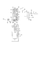
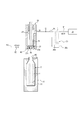
- the liquid blow molding method of the present invention can be carried out using, for example, the liquid blow molding device 1 configured as shown in FIG.
- the liquid blow molding apparatus 1 shown in FIG. 1 is a liquid blow molding of a preform 2 made of synthetic resin, and molded into a liquid-containing container containing a content liquid inside.
- the liquid blow molding is a blow molding performed using a pressurized liquid instead of pressurized air used in air blow molding as a pressure medium (pressure fluid) supplied to the preform 2. It is.
- liquid L supplied to the preform 2 that is, the content liquid L contained in the liquid-containing container after molding
- various liquids such as beverages, cosmetics, medicines, detergents, and toiletries such as shampoo can be used, for example.
- thermoplastic synthetic resin material such as polypropylene (PP) or polyethylene terephthalate (PET) is connected to the cylindrical opening 2a serving as the opening end and the opening 2a and the lower end is closed. It is preferable to use one formed in a bottomed cylindrical shape having a cylindrical body 2b.
- the preform 2 if it has the opening part 2a not only the thing of the said shape, the thing of various shapes can be used according to the shape etc. of the container after shaping
- a closure cap (not shown) is attached to the opening 2a of the liquid container after molding by undercutting (under cut engagement)
- An engagement protrusion is provided on the outer wall surface of the opening 2a.
- a male screw may be provided to attach the closure cap to the opening 2a by screw connection.
- the liquid blow molding apparatus 1 has a mold 10 for blow molding.
- the mold 10 has a cavity 11 having a shape corresponding to the final shape of the container, for example, a bottle shape.
- the cavity 11 opens upward at the upper surface of the mold 10.
- the preform 2 is mounted on the mold 10 in a state where the body 2 b is disposed inside the cavity 11 of the mold 10 and the opening 2 a protrudes upward from the mold 10.
- the mold 10 can be opened to the left and right, and after the preform 2 is formed into a liquid-filled container, the liquid-filled container is removed from the mold 10 by opening the mold 10 to the left and right. be able to.
- the nozzle unit 20 for supplying the liquid L to the inside of the preform 2 is provided.
- the nozzle unit 20 has a main body block 21 which is movable relative to the mold 10 in the vertical direction.
- a support block 22 is provided at the lower end of the main body block 21, and is supported by the support block 22, and a blow nozzle 23 is mounted at the lower end of the main body block 21.
- the blow nozzle 23 is formed in a substantially cylindrical shape, and is a preform attached to the mold 10 when the nozzle unit 20 moves relative to the mold 10 to the stroke end in the direction approaching the mold 10. It engages with the mouth 2 of 2 from the upper side in a sealing state.
- the inner part of the cylindrical part of the blow nozzle 23 is a liquid supply port 23a. Further, the cylindrical portion constituting the liquid supply port 23a of the blow nozzle 23 is provided with a discharge port 23b opened at the lower end of the cylindrical portion. In the present embodiment, eight discharge ports 23 b are provided at equal intervals in the circumferential direction in the cylindrical portion of the blow nozzle 23, but the number can be changed variously.
- a supply path 24 extending in the vertical direction is provided inside the main body block 21.
- the supply path 24 is a flow path for supplying the liquid L to the liquid supply port 23 a of the blow nozzle 23, and the lower end thereof communicates with the liquid supply port 23 a of the blow nozzle 23.
- the main body block 21 is provided with a supply port 25 communicating with the upper end of the supply path 24.
- a seal body 26 for opening and closing the liquid supply port 23 a of the blow nozzle 23 is disposed in the supply path 24.
- the seal body 26 is fixed to the lower end of a shaft body 27 provided to be movable in the vertical direction with respect to the nozzle unit 20, and is movable in the vertical direction inside the supply passage 24.
- the seal body 26 is formed in a cylindrical shape and abuts on the upper surface of the blow nozzle 23 at the lower end face when moving to the closed position which is the lower stroke end position to close the liquid supply port 23a of the blow nozzle 23 Do.
- the seal body 26 moves upward from the closed position, the liquid supply port 23 a of the blow nozzle 23 is opened and communicated with the supply path 24.
- the seal body 26 may be formed integrally with the shaft body 27.
- the liquid blow molding apparatus 1 can also be configured with a draw rod 28.
- the extension rod 28 is inserted in the axial center of the shaft body 27 so as to be movable relative to the shaft body 27 in the vertical direction, penetrates the axial center of the seal body 26 and can project from the lower end of the seal body 26 It is provided.
- the preform 2 can be axially stretched by moving the stretching rod 28 downward by being driven by a drive source (not shown).
- the liquid blow molding device 1 applies the pressurized liquid L supplied from the opening 2 a while stretching the preform 2 in the axial direction by the extension rod 28.
- the liquid blow molding apparatus 1 may be configured to perform liquid blow molding only with the liquid L in which the preform 2 is pressurized without providing the drawing rod 28.
- the pump 30 is connected to the supply port 25 by a pipe P1.
- the pump 30 can be configured, for example, as a plunger pump including a cylinder 30a and a piston (plunger) 30b.
- a supply tank 31 is connected to the pump 30.
- the supply tank 31 can be configured to store the liquid L and to heat the liquid L to a predetermined temperature and maintain the temperature at the predetermined temperature.
- An on-off valve V1 is provided in a flow passage between the pump 30 and the supply tank 31, and the on-off valve V1 can open and close the flow passage.
- symbol 32 is a pressure gauge provided in piping P1.
- the plurality of discharge ports 23 b provided in the blow nozzle 23 are connected to the connection passage 23 c annularly provided on the outer peripheral surface of the blow nozzle 23 by a flow passage extending upward and bending outward in the radial direction. It is in communication.
- the connection path 23 c is connected to the connection port 22 a on the side surface of the support block 22.
- a pipe P2 is connected to the connection port 22a, and the connection port 22a is connected to a discharge tank (not shown) via the pipe P2. That is, the plurality of discharge ports 23 b provided in the blow nozzle 23 are connected to the discharge tank, respectively.
- the pipe P2 may be connected to a suction pump for discharge instead of the discharge tank.
- the pipe P2 is provided with an on-off valve V2 for opening and closing the pipe P2.
- the pump 30 is pressurized to a predetermined pressure by operating in the positive direction (pressing direction) in a state where the seal body 26 moves upward and the liquid supply port 23a is opened and the on-off valve V1 is closed.
- the liquid L can be supplied to the inside of the preform 2 through the pipe P1, the supply port 25, the supply path 24, and the liquid supply port 23a of the blow nozzle 23.
- the liquid supply port 23a is closed by the seal body 26 and the on / off valve V1 is opened in the reverse direction to operate the liquid L stored in the supply tank 31 inside the cylinder 30a. To prepare for the next liquid blow molding.
- the liquid blow molding device 1 is provided with a rotation drive unit 40 for rotating the preform 2 mounted on the mold 10 about the axial center of the opening 2a.
- the rotary drive unit 40 is provided on the outer peripheral surface of the distal end portion of the blow nozzle 23 so as to be rotatable relative to the distal end portion and the opening 2 a of the preform 2. It has a gripping portion 40a which can be gripped from the inside, and a drive mechanism 40b which is disposed radially outside the gripping portion 40a with the opening 2a of the preform 2 interposed therebetween, and which rotationally drives the gripping portion 40a.
- the drive mechanism 40b can transmit the driving force from a drive source (not shown) such as an electric motor to the grip portion 40a.
- the rotary drive unit 40 having such a configuration rotates the grip portion 40a by the drive mechanism 40b in a state where the grip portion 40a grips the mouth portion 2a of the preform 2, thereby opening the preform 2 together with the grip portion 40a.
- the center of the axis of the part 2a can be rotated.
- the gripping portion 40a is a seal that grips the opening 2a in a state of being in fluid tight contact with the inner surface of the opening 2a of the preform 2 and prevents liquid leakage from the opening 2a of the preform 2 Also works.
- the rotation speed of the preform 2 by the rotation drive unit 40 is appropriately set according to the type, viscosity, and the like of the liquid L.
- the preform 2 is formed by rotating the holding portion 40a provided at the tip end side portion of the blow nozzle 23 for holding the mouth 2a of the preform 2 by the drive mechanism 40b.
- the configuration is such that the center of the axis of the portion 2a is rotated, but the configuration is not limited to this, and the configuration can be changed variously as long as the preform 2 can be rotated about the axis of the opening 2a.
- a bottom pin is provided which protrudes from the bottom portion of the mold 10 toward the inside of the cavity 11, and the bottom pin of the preform 2 is gripped by the bottom pin and the preform 2 is opened by rotating the bottom pin. It may be configured to rotate around the axial center of the part 2a.
- the mold 2 may be configured to be rotated about the axis of the opening 2a together with the mold 10.
- the opening 2a of the preform 2 is gripped by the grip portion provided at the tip of the arm member inserted from the side between the mold 10 and the nozzle unit 20, and the arm member is rotated to rotate the arm member
- the preform 2 may be configured to be rotated about the axial center of the opening 2a.
- the preform 2 is formed by rotating the holding portion 40a provided on the tip end side of the blow nozzle 23 and holding the opening 2a of the preform 2 by the drive mechanism 40b.
- the opening portion 2a of the preform 2 is gripped by a holding portion provided at the tip of an arm member inserted from the side of the mold 10 and the nozzle unit 20 so as to rotate about the axial center,
- the preform 2 is deformed because the opening 2a is not stretched. It is preferable because it can be difficult.
- the operations of the nozzle unit 20, the seal body 26, the extension rod 28, the pump 30, the on-off valves V1 and V2, the rotary drive unit 40, and the like are integrally controlled by a control device (not shown). This control can be performed with reference to the value of the pressure gauge 32 or the like.
- the on-off valves V1 and V2 are preferably configured by solenoid valves that can be controlled by the control device.
- a liquid filled container C is formed from the preform 2 made of synthetic resin and containing the liquid (content liquid) L inside the container of a predetermined shape.
- a method (a liquid blow molding method according to the present embodiment) will be described.
- the nozzle unit 20 in a state where the nozzle unit 20 is separated upward with respect to the blow molding die 10, the extent to which the stretchability is expressed in advance using a heating means (not shown) such as a heater
- a heating means such as a heater
- the preform 2 made of a synthetic resin which has been heated to a predetermined temperature (for example, 80 ° C. to 150 ° C.) is attached to the mold 10 and clamped.
- a predetermined temperature for example, 80 ° C. to 150 ° C.
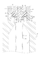
- FIGS. 1 and 2 show the completed state of the nozzle engagement step in which the blow nozzle 23 is engaged in a liquid tight state with the opening 2 a of the preform 2.
- the inner peripheral surface of the opening 2a of the preform 2 is gripped by the grip 40a of the rotation drive unit 40 and sealed in a liquid tight manner.
- the seal body 26 and the on-off valve V1 are closed, and the on-off valve V2 is open. Further, the drawing rod 28 is held at the original position not to project downward from the blow nozzle 23.
- a gas-liquid replacement process is next performed.
- the seal body 26 is moved upward to open the liquid supply port 23a of the blow nozzle 23 with the on-off valve V2, ie, the outlet 23b open.
- the pump 30 is operated in the forward direction (pressure direction).
- the pump 30 operates, the liquid L is supplied to the inside of the preform 2 through the pipe P1, the supply port 25, the supply path 24, and the liquid supply port 23a of the blow nozzle 23.
- the liquid L is supplied to the inside of the preform 2 in a state where the discharge port 23 b provided in the blow nozzle 23 is opened and communicated with the discharge tank.
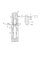
- the liquid L is supplied to the inside, the air inside the preform 2 is pushed out from the outlet 23 b toward the discharge tank and discharged, and the inside of the preform 2 is replaced with the liquid L from the air. That is, by performing the gas-liquid replacement step, the air inside the preform 2 is replaced with the liquid L, and as shown in FIG. 5, the inside of the preform 2 remains as it was before being blow molded.
- the liquid L can be filled.
- the gas-liquid replacement step it is preferable to supply a predetermined amount of liquid L to the inside of the preform 2 at a lower pressure than the blow molding step described later. That is, in the gas-liquid replacement step, it is preferable to operate by adjusting the output of the pump 30 so as to supply the liquid L at a pressure at which the preform 2 is not blow molded or slightly blow molded. .
- the gas-liquid separation step is performed before the blow molding of the preform 2. It is like that.
- the rotary drive unit 40 is operated to rotate the preform 2 about the axial center of the opening 2 a to separate the air from the liquid L inside the preform 2.
- the air mixed in the liquid L is moved to the side of the opening 2 a of the preform 2 and the outside from the discharge port 23 b provided in the blow nozzle 23 Can be discharged efficiently.
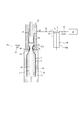
- the gas-liquid separation process is performed while performing the gas-liquid replacement process. That is, in the present embodiment, as shown in FIGS. 4 and 5, the gas-liquid replacement process is performed in a state in which the preform 2 is rotated about the axis of the opening 2a by the rotary drive unit 40, The liquid L is supplied into the rotating preform 2 through the liquid supply port 23 a of the blow nozzle 23.
- the liquid L supplied to the inside of the preform 2 is spiraled from the side of the opening 2 a to the side of the bottom while being pressed toward the inner surface of the body 2 b of the preform 2 by the centrifugal force due to the rotation of the preform 2 It is accumulated on the side of the bottom of the preform 2 while being separated from the air by flowing like a shape.
- the air separated from the liquid L moves above the preform 2 and is discharged from the discharge port 23 b provided separately from the liquid supply port 23 a in the blow nozzle 23.
- the air mixed in the liquid L is separated from the liquid L by supplying the liquid L to the inside of the preform 2 while rotating the preform 2 about the axial center of the opening 2a.
- the inside of the preform 2 can be filled with the liquid L while efficiently discharging it from the discharge port 23b to the outside. Therefore, the amount of air remaining inside the preform 2 after completion of the gas-liquid replacement process can be reduced.
- the liquid L is a relatively viscous liquid such as a shampoo or a liquid detergent
- the liquid L containing air is supplied to the inside of the preform 2 or is supplied to the inside of the preform 2
- the liquid L contained therein contains air in the interior of the preform 2 and contains a large amount of air, but even in such a case, the liquid L is mixed with the liquid L by performing the gas-liquid separation step. It is possible to separate the existing air from the liquid L and efficiently discharge it from the discharge port 23b to the outside.
- the gas-liquid separation step may be performed after completion of the gas-liquid replacement step without being performed during the gas-liquid replacement step. Even in this case, the preform 2 in which the inside is filled with the liquid L in the gas-liquid replacement step is rotated about the axis of the opening 2a in the gas-liquid separation step. Thus, the air mixed in the liquid L can be separated from the liquid L and discharged to the outside from the discharge port 23 b. Therefore, the amount of air remaining inside the preform 2 after completion of the gas-liquid replacement process can be reduced.
- the gas-liquid separation step can be performed continuously both during the gas-liquid replacement step and after the completion of the gas-liquid replacement step.
- the liquid 2 is mixed with the liquid L inside the preform 2 by rotating the preform 2 about the axial center of the opening 2 a in the gas-liquid separation step. Can be separated from the liquid L and discharged efficiently from the outlet 23b to the outside, so that the amount of air remaining inside the preform 2 can be reduced after the completion of the gas-liquid replacement step. .
- a blow molding step is then performed.
- the on-off valves V1 and V2 are closed, the rotary drive unit 40 is stopped, and the pump 30 is normally operated with the seal body 26 open. Activate further in the direction.
- the pump 30 operates with an output such that the pressure of the liquid L supplied to the preform 2 becomes a predetermined pressure at which the preform 2 can be blow-molded.
- the preform 2 is stretched in an expanded state by the pressure of the liquid L.
- the preform 2 is molded (liquid blow molding) until it becomes a liquid-containing container C having a predetermined shape along the inner surface of the cavity 11, the operation of the pump 30 is stopped and the blow molding is performed. The process is complete.
- the air inside the preform 2 is replaced with the liquid L in the gas-liquid replacement step, and the amount of air remaining inside the preform 2 is further reduced by performing the gas-liquid separation step. Since the pressure is reduced, it is suppressed that air is entrapped in the liquid L supplied to the inside of the preform 2 in the blow molding process and the liquid L is generated in the inside of the preform 2, and the molding conditions are thereby reduced. And stabilize the formability of the container. Therefore, the container C containing liquid can be manufactured precisely and at low cost so as to have a predetermined internal volume and shape.
- the stretch rod 28 When the stretch rod 28 is provided in the liquid blow molding apparatus 1, the stretch rod 28 is advanced toward the inside of the preform 2 in the blow molding process, and the preform 2 is axially (longitudinal) by the stretch rod 28. Stretch to Thereby, biaxial stretch blow molding can be performed in which the preform 2 is biaxially stretched by the pressure of the liquid L and the stretch rod 28. According to the biaxial stretch blow molding, the preform 2 can be molded into the liquid-containing container C having a predetermined shape more accurately.
- the suck back process is performed.
- the pump 30 is operated in the reverse direction with the seal body 26 in the open position and the liquid supply port 23a of the blow nozzle 23 open, and the predetermined shape is obtained in the blow molding step.
- a predetermined amount of liquid L is sucked back (sucked back) from the inside of the container C containing liquid into the supply passage 24 through the liquid supply port 23a.
- the amount of the liquid L sucked back to the supply path 24 in the suck back step is appropriately set so that the head space HS provided inside the liquid-filled container C after completion is a predetermined amount.
- the internal volume of the liquid container C is reduced by the amount of the liquid L sucked back to the supply passage 24, and a volume reduction deformation state in which a gap is generated between the liquid container C and the cavity 11 The inside becomes a negative pressure state lower than atmospheric pressure.
- the air inside the preform 2 is replaced with the liquid L in the gas-liquid replacement step, and the amount of air remaining inside the preform 2 is further reduced by performing the gas-liquid separation step. Therefore, even if the liquid L is drawn back from the container C containing liquid to the inside of the supply path 24 by suckback, the liquid L inside the supply path 24 is not mixed with much air, and the liquid to be performed next is performed In the blow molding process, deterioration of moldability does not occur.
- the blow nozzle 23 is driven by the seal body 26 in a state where the predetermined amount of liquid L is absorbed back to the supply passage 24 from the inside of the liquid filled container C formed into the predetermined shape in the suck back process.
- the nozzle unit 20 is relatively moved in the direction away from the mold 10 as shown in FIG. 8, and the blow nozzle 23 is detached from the opening 2a of the preform 2.
- the engagement with the mouth 2a of the When the blow nozzle 23 separates from the opening 2a of the container C containing liquid after molding, the container C containing liquid which has been reduced in volume in the suckback process is restored to the original shape, and the container C containing liquid is contained.
- a predetermined amount of head space HS is formed above the predetermined amount of liquid L.
- the on-off valve V2 before opening the blow nozzle 23, it is made to communicate with the outside air, and the liquid-containing container C, which has been reduced in volume in the suckback process, is restored to its original shape, and head space
- the HS may be formed.
- a cap is attached to the opening 2a by a capping device (not shown), and then the mold 10 is opened, and the completed container C containing liquid is taken out of the mold 10.
- the cap may be attached after the liquid-filled container C is taken out of the mold 10.
- the draw rod 28 When the draw rod 28 is provided in the liquid blow molding apparatus 1, the draw rod 28 may be pulled out from the container C containing liquid after the liquid supply port 23 a of the blow nozzle 23 is closed by the seal body 26. As a result, compared to the case where the stretch rod 28 is not provided in the liquid blow molding device 1, the amount of the head space HS can be further increased by the volume integral of the stretch rod 28. In this case, the amount of the liquid L sucked back into the supply path 24 from the inside of the liquid-filled container C in the suck back process may be set in consideration of the volume of the extension rod 28 inserted into the liquid-filled container C.
- the air inside the preform 2 is replaced with the liquid L in the gas-liquid replacement step, and the inside of the preform 2 is obtained by performing the gas-liquid separation step. Since the amount of air remaining in the chamber is further reduced, the air is entrained in the liquid L supplied to the inside of the preform 2 in the blow molding process, and bubbles etc. occur in the liquid L inside the preform 2.
- the container C containing liquid can be manufactured precisely and at low cost so as to have a predetermined internal volume and shape.
- the preform is produced without causing foaming or the like in the liquid L.
- the air inside 2 can be replaced by liquid L.
- the liquid L supplied to the inside of the preform 2 in the gas-liquid replacement process is The centrifugal force of the preform 2 rotated in the gas-liquid separation process causes the flow to spiral from the side of the opening 2 a to the side of the bottom while being pressed toward the inner surface of the body 2 b of the preform 2
- the air can be efficiently separated from the liquid L supplied to the preform 2. This can further reduce the amount of air remaining inside the preform 2.
- the gas-liquid separation step is performed after the completion of the gas-liquid replacement step, the air on the bottom side of the preform 2 is also reliably separated from the liquid L, so that the inside of the preform 2 is formed. The amount of air remaining in can be further reduced.
- the preform 2 in the gas-liquid separation step, is gripped by the grip portion 40a provided on the blow nozzle 23, and the preform 2 is rotated together with the grip portion 40a.
- the preform 2 can be reliably rotated without causing the preform 2 to be deformed.
- the container C containing liquid can be formed more accurately from the preform 2.
- the liquid blow molding method of the present embodiment includes a nozzle engagement step of causing the blow nozzle 23 to engage with the opening 2a before the gas-liquid replacement step, and in the gas-liquid replacement step, While the liquid L is supplied to the inside of the preform 2 from the opening 2a through the liquid supply port 23a, the air inside the preform 2 is externally supplied from the discharge port 23b provided in the blow nozzle 23 separately from the liquid supply port 23a. Since the discharge is performed, the air inside the preform 2 can be discharged to the outside without leaking the liquid L to the outside.
- the liquid blow molding method of the present invention is performed using the liquid blow molding device 1 having the configuration shown in FIG.
- the liquid blow molding method of the invention can also be performed.
- the discharge port 23b for discharging the air inside the preform 2 to the outside in the gas-liquid replacement step is provided in the blow nozzle 23. It may be provided at the site.
- the opening 2a of the preform 2 is gripped by the grip portion 40a provided on the tip end side portion of the blow nozzle 23, and the grip portion 40a is rotated by the drive mechanism 40b.
- the preform 2 is rotated about the axial center of the opening 2a, but the present invention is not limited thereto.
- the preform 2 can be rotated about the axial center of the opening 2a, for example, , Hold the bottom portion of the preform 2 by the bottom pin protruding from the bottom portion of the mold 10 toward the inside of the cavity 11, and rotate the bottom pin to center the preform 2 at the center of the opening 2a.
- the mold 10 By rotating the mold 10 while holding the neck portion of the preform 2 by the mold 10 as it rotates Is rotated about the axial center of the opening 2a, or the opening of the preform 2 is held by a grip provided at the tip of an arm member inserted from the side of the mold 10 to the nozzle unit 20 from the side.
- the configuration can be variously changed, for example, by rotating the arm member (gripping portion) and rotating the preform 2 together with the arm member about the axis of the opening 2a.
- rotational speed and the rotational direction of the preform 2 by the rotational drive unit 40 can be changed variously.
- the air inside the preform 2 is discharged to the outside from the discharge port 23b provided in the blow nozzle 23, but the invention is not limited thereto.
- the blow nozzle 23 is lowered to a first position where the mouth 2a is not sealed (first nozzle lowering process), and in the gas-liquid replacement process, the blow nozzle 23 at the first position
- the air inside the preform 2 may be discharged to the outside from the gap between the blow nozzle 23 and the opening 2 a while supplying the liquid L to the inside of the reform 2.
- the blow nozzle 23 is lowered to a second position where the mouth 2a is sealed (second nozzle lowering step), and then the blow molding step is performed.
- the provision of the discharge port 23b in the blow nozzle 23 is unnecessary, the configuration of the liquid blow molding apparatus 1 is simplified, and the manufacturing cost of the liquid-containing container C molded by the liquid blow molding method is reduced. it can.
- the blowout nozzle 23 is lowered to the first position with the rotary drive unit 40 fitted in a fluid-tight manner to the opening 2a of the preform 2 in advance.
- the air inside the preform 2 is discharged to the outside from the gap between the rotary drive unit 40 and the rotary drive unit 40, and then, when the blow nozzle 23 is lowered to the second position, between the blow nozzle 23 and the rotary drive unit 40 Or, when the blow nozzle 23 is lowered to the first position, the rotary drive unit 40 is fluid-tightly fitted to the opening 2 a of the preform 2 and the rotary drive unit 40 is closed.
- Such as the configuration of the blow nozzle 23 to the rotary drive unit 40 can be variously modified.
- the head space HS is increased by pulling the stretch rod 28 out of the liquid-containing container C.
- the head space HS may not be formed by the drawing rod 28 (for example, the drawing rod 28 may be pulled out before the end of the blow molding process).
- the pump 30 is a plunger pump in the embodiment, the invention is not limited to this, and the liquid L can be pressurized to a predetermined pressure and supplied to the preform 2 and after molding Pumps of various configurations can be used as long as they can suck back a predetermined amount of liquid L from the inside of the liquid-filled container C.
- the liquid blow molding method of the present invention requires a large head space HS as in a container C containing a liquid used for a pump-equipped container for containing a relatively viscous content such as a shampoo or a liquid detergent.
- a relatively viscous content such as a shampoo or a liquid detergent.
- molding it is also applicable to shaping
- the gas-liquid separation step may be performed during the blow molding step or after the blow molding step, but since the blow molding step is basically performed with the preform 2 sealed, the liquid L It is difficult to remove the air separated from the outside. Therefore, the gas-liquid separation step is preferably performed together with the gas-liquid replacement step or after the gas-liquid replacement step and before the blow molding step.
Landscapes
- Engineering & Computer Science (AREA)
- Mechanical Engineering (AREA)
- Manufacturing & Machinery (AREA)
- Blow-Moulding Or Thermoforming Of Plastics Or The Like (AREA)
Abstract
La présente invention concerne un procédé de moulage par soufflage de liquide pour mouler, afin d'obtenir un récipient (C) contenant un liquide ayant une forme prescrite, une préforme en résine synthétique (2) ayant un bec verseur (2a), ledit procédé étant caractérisé en ce qu'il comprend : une étape de remplacement air-liquide pour évacuer l'air dans la préforme (2) vers l'extérieur tout en fournissant un liquide (L) dans la préforme (2) à partir du bec verseur (2a) à travers une buse de soufflage (23) ; une étape de séparation air-liquide pour séparer l'air du liquide (L) dans la préforme (2) par rotation de la préforme (2) autour de l'axe du bec verseur (2a) ; et une étape de moulage par soufflage pour, après la réalisation de l'étape de séparation air-liquide, mouler la préforme (2) afin d'obtenir un récipient ayant la forme prescrite en fournissant le liquide sous pression (L) dans la préforme (2) à partir du bec verseur (2a) à travers la buse de soufflage (23).
Priority Applications (3)
| Application Number | Priority Date | Filing Date | Title |
|---|---|---|---|
| CN201880075277.7A CN111372751A (zh) | 2017-11-30 | 2018-10-03 | 液体吹塑成型方法 |
| EP18883542.5A EP3718740B1 (fr) | 2017-11-30 | 2018-10-03 | Procédé de moulage par soufflage de liquide |
| US16/765,566 US10940632B2 (en) | 2017-11-30 | 2018-10-03 | Liquid blow molding method |
Applications Claiming Priority (2)
| Application Number | Priority Date | Filing Date | Title |
|---|---|---|---|
| JP2017230492A JP6893861B2 (ja) | 2017-11-30 | 2017-11-30 | 液体ブロー成形方法 |
| JP2017-230492 | 2017-11-30 |
Publications (1)
| Publication Number | Publication Date |
|---|---|
| WO2019106955A1 true WO2019106955A1 (fr) | 2019-06-06 |
Family
ID=66665652
Family Applications (1)
| Application Number | Title | Priority Date | Filing Date |
|---|---|---|---|
| PCT/JP2018/037104 Ceased WO2019106955A1 (fr) | 2017-11-30 | 2018-10-03 | Procédé de moulage par soufflage de liquide |
Country Status (5)
| Country | Link |
|---|---|
| US (1) | US10940632B2 (fr) |
| EP (1) | EP3718740B1 (fr) |
| JP (1) | JP6893861B2 (fr) |
| CN (1) | CN111372751A (fr) |
| WO (1) | WO2019106955A1 (fr) |
Families Citing this family (3)
| Publication number | Priority date | Publication date | Assignee | Title |
|---|---|---|---|---|
| JP7184462B2 (ja) * | 2019-01-31 | 2022-12-06 | 株式会社吉野工業所 | 内容液入りボトルの製造方法 |
| DE102019114953A1 (de) * | 2019-06-04 | 2020-12-10 | Khs Corpoplast Gmbh | Verfahren und Vorrichtung zum Herstellen von mit flüssigem Füllgut befüllten Behältern aus thermisch konditionierten Vorformlingen |
| CN112694241A (zh) * | 2021-02-26 | 2021-04-23 | 深圳市应有仁建材有限公司 | 一种根据吹气量来调整气泵进气的玻璃吹管装置 |
Citations (7)
| Publication number | Priority date | Publication date | Assignee | Title |
|---|---|---|---|---|
| JPS586929B2 (ja) | 1975-06-10 | 1983-02-07 | アサヒコウガクコウギヨウ カブシキガイシヤ | ジドウロコウセイギヨカメラニオケル ハツシンシユウキガジカンノシスウデヘンカスルハツシンキ |
| JP2000043129A (ja) * | 1998-07-29 | 2000-02-15 | Ishikawajima Harima Heavy Ind Co Ltd | プラスチック容器の成形方法 |
| JP2015506288A (ja) * | 2011-12-21 | 2015-03-02 | アムコー リミテッド | 成形装置のシールシステム |
| JP2016537227A (ja) * | 2013-10-21 | 2016-12-01 | ディスクマ アクチェンゲゼルシャフト | 共通部分を有する第1閉ループ及び第2閉ループを備えた、容器を形成かつ充填する装置 |
| JP2016210037A (ja) * | 2015-04-30 | 2016-12-15 | 株式会社吉野工業所 | 液体ブロー成形装置 |
| WO2018079012A1 (fr) * | 2016-10-28 | 2018-05-03 | 株式会社吉野工業所 | Procédé de moulage par soufflage de liquide |
| WO2018198449A1 (fr) * | 2017-04-27 | 2018-11-01 | 株式会社吉野工業所 | Procédé de production d'un récipient contenant un liquide |
Family Cites Families (12)
| Publication number | Priority date | Publication date | Assignee | Title |
|---|---|---|---|---|
| JPH01132369A (ja) * | 1987-11-18 | 1989-05-24 | Asahi Breweries Ltd | 発泡飲料のガス抜き方法 |
| FR2804059B1 (fr) * | 2000-01-20 | 2002-08-30 | Sidel Sa | Machine de soufflage de recipients comportant des moyens d'orientation des preformes dans le moule de soufflage |
| FR2962930B1 (fr) * | 2010-07-20 | 2012-08-31 | Sidel Participations | Procede de formage d'un recipient par soufflage et remplissage |
| JP5806929B2 (ja) | 2011-12-27 | 2015-11-10 | 株式会社吉野工業所 | ブロー成形装置およびブロー成形容器の製造方法 |
| JP5870001B2 (ja) * | 2012-09-28 | 2016-02-24 | 株式会社吉野工業所 | ブロー成形装置及び容器の製造方法 |
| EP2988918B1 (fr) * | 2013-04-24 | 2016-11-16 | Discma AG | Procédé et machine de fabrication de contenants en plastique |
| JP6100137B2 (ja) * | 2013-09-30 | 2017-03-22 | 株式会社吉野工業所 | ブロー成形装置 |
| EP2860016B1 (fr) * | 2013-10-10 | 2017-03-01 | Discma AG | Procédé de distribution d'un volume de liquide et appareil associé |
| EP2930005B1 (fr) * | 2014-04-08 | 2017-06-07 | Discma AG | Machine rotative et procédé de formage hydraulique de récipients formés |
| DE102014016140A1 (de) * | 2014-10-30 | 2016-05-04 | Khs Corpoplast Gmbh | Verfahren zur Entfernung von Luft aus Vorformlingen zur Herstellung von gefüllten Behältern aus Kunststoff |
| EP3109029B1 (fr) * | 2015-06-25 | 2017-12-13 | Discma AG | Station de formage pour former un récipient à partir d'une préforme comprenant une tige d'étirage vibrante, méthode de fabrication d'un récipient utilisant ladite station de formage, méthode d'élimination de la mousse dans le col d'un container utilisant ladite station de formage et méthode de nettoayge de la station de formage. |
| JP6594823B2 (ja) * | 2016-04-28 | 2019-10-23 | 株式会社吉野工業所 | 液体ブロー成形方法 |
-
2017
- 2017-11-30 JP JP2017230492A patent/JP6893861B2/ja active Active
-
2018
- 2018-10-03 WO PCT/JP2018/037104 patent/WO2019106955A1/fr not_active Ceased
- 2018-10-03 EP EP18883542.5A patent/EP3718740B1/fr active Active
- 2018-10-03 US US16/765,566 patent/US10940632B2/en active Active
- 2018-10-03 CN CN201880075277.7A patent/CN111372751A/zh active Pending
Patent Citations (7)
| Publication number | Priority date | Publication date | Assignee | Title |
|---|---|---|---|---|
| JPS586929B2 (ja) | 1975-06-10 | 1983-02-07 | アサヒコウガクコウギヨウ カブシキガイシヤ | ジドウロコウセイギヨカメラニオケル ハツシンシユウキガジカンノシスウデヘンカスルハツシンキ |
| JP2000043129A (ja) * | 1998-07-29 | 2000-02-15 | Ishikawajima Harima Heavy Ind Co Ltd | プラスチック容器の成形方法 |
| JP2015506288A (ja) * | 2011-12-21 | 2015-03-02 | アムコー リミテッド | 成形装置のシールシステム |
| JP2016537227A (ja) * | 2013-10-21 | 2016-12-01 | ディスクマ アクチェンゲゼルシャフト | 共通部分を有する第1閉ループ及び第2閉ループを備えた、容器を形成かつ充填する装置 |
| JP2016210037A (ja) * | 2015-04-30 | 2016-12-15 | 株式会社吉野工業所 | 液体ブロー成形装置 |
| WO2018079012A1 (fr) * | 2016-10-28 | 2018-05-03 | 株式会社吉野工業所 | Procédé de moulage par soufflage de liquide |
| WO2018198449A1 (fr) * | 2017-04-27 | 2018-11-01 | 株式会社吉野工業所 | Procédé de production d'un récipient contenant un liquide |
Non-Patent Citations (1)
| Title |
|---|
| See also references of EP3718740A4 |
Also Published As
| Publication number | Publication date |
|---|---|
| US20200307062A1 (en) | 2020-10-01 |
| EP3718740A4 (fr) | 2021-08-11 |
| JP2019098594A (ja) | 2019-06-24 |
| EP3718740B1 (fr) | 2022-04-27 |
| CN111372751A (zh) | 2020-07-03 |
| JP6893861B2 (ja) | 2021-06-23 |
| US10940632B2 (en) | 2021-03-09 |
| EP3718740A1 (fr) | 2020-10-07 |
Similar Documents
| Publication | Publication Date | Title |
|---|---|---|
| JP6594823B2 (ja) | 液体ブロー成形方法 | |
| JP6632872B2 (ja) | 液体ブロー成形方法 | |
| US11400637B2 (en) | Liquid blow molding method | |
| JP2018183973A (ja) | 液体入り容器の製造方法 | |
| EP3663071A1 (fr) | Dispositif et procédé de fabrication d'un récipient rempli de liquide | |
| WO2019106955A1 (fr) | Procédé de moulage par soufflage de liquide | |
| WO2019003698A1 (fr) | Méthode de fabrication d'un récipient rempli de liquide | |
| US11504897B2 (en) | Liquid container manufacturing method | |
| WO2018179747A1 (fr) | Procédé de fabrication de récipient | |
| CN110545983B (zh) | 装有液体的容器的制造方法 | |
| EP3718738B1 (fr) | Méthode de moulage par soufflage de liquide | |
| JP7710408B2 (ja) | 液体ブロー成形方法 | |
| CN111655446A (zh) | 液体吹塑成型装置 |
Legal Events
| Date | Code | Title | Description |
|---|---|---|---|
| 121 | Ep: the epo has been informed by wipo that ep was designated in this application |
Ref document number: 18883542 Country of ref document: EP Kind code of ref document: A1 |
|
| NENP | Non-entry into the national phase |
Ref country code: DE |
|
| ENP | Entry into the national phase |
Ref document number: 2018883542 Country of ref document: EP Effective date: 20200630 |