WO2019107182A1 - Dispositif de codage, procédé de codage, dispositif de décodage, et procédé de décodage - Google Patents
Dispositif de codage, procédé de codage, dispositif de décodage, et procédé de décodage Download PDFInfo
- Publication number
- WO2019107182A1 WO2019107182A1 PCT/JP2018/042428 JP2018042428W WO2019107182A1 WO 2019107182 A1 WO2019107182 A1 WO 2019107182A1 JP 2018042428 W JP2018042428 W JP 2018042428W WO 2019107182 A1 WO2019107182 A1 WO 2019107182A1
- Authority
- WO
- WIPO (PCT)
- Prior art keywords
- unit
- prediction
- image
- pixel
- tap
- Prior art date
- Legal status (The legal status is an assumption and is not a legal conclusion. Google has not performed a legal analysis and makes no representation as to the accuracy of the status listed.)
- Ceased
Links
Images


Classifications
-
- H—ELECTRICITY
- H04—ELECTRIC COMMUNICATION TECHNIQUE
- H04N—PICTORIAL COMMUNICATION, e.g. TELEVISION
- H04N19/00—Methods or arrangements for coding, decoding, compressing or decompressing digital video signals
- H04N19/80—Details of filtering operations specially adapted for video compression, e.g. for pixel interpolation
-
- H—ELECTRICITY
- H04—ELECTRIC COMMUNICATION TECHNIQUE
- H04N—PICTORIAL COMMUNICATION, e.g. TELEVISION
- H04N19/00—Methods or arrangements for coding, decoding, compressing or decompressing digital video signals
- H04N19/10—Methods or arrangements for coding, decoding, compressing or decompressing digital video signals using adaptive coding
- H04N19/169—Methods or arrangements for coding, decoding, compressing or decompressing digital video signals using adaptive coding characterised by the coding unit, i.e. the structural portion or semantic portion of the video signal being the object or the subject of the adaptive coding
- H04N19/182—Methods or arrangements for coding, decoding, compressing or decompressing digital video signals using adaptive coding characterised by the coding unit, i.e. the structural portion or semantic portion of the video signal being the object or the subject of the adaptive coding the unit being a pixel
-
- H—ELECTRICITY
- H04—ELECTRIC COMMUNICATION TECHNIQUE
- H04N—PICTORIAL COMMUNICATION, e.g. TELEVISION
- H04N19/00—Methods or arrangements for coding, decoding, compressing or decompressing digital video signals
- H04N19/10—Methods or arrangements for coding, decoding, compressing or decompressing digital video signals using adaptive coding
- H04N19/102—Methods or arrangements for coding, decoding, compressing or decompressing digital video signals using adaptive coding characterised by the element, parameter or selection affected or controlled by the adaptive coding
- H04N19/117—Filters, e.g. for pre-processing or post-processing
-
- H—ELECTRICITY
- H04—ELECTRIC COMMUNICATION TECHNIQUE
- H04N—PICTORIAL COMMUNICATION, e.g. TELEVISION
- H04N19/00—Methods or arrangements for coding, decoding, compressing or decompressing digital video signals
- H04N19/10—Methods or arrangements for coding, decoding, compressing or decompressing digital video signals using adaptive coding
- H04N19/169—Methods or arrangements for coding, decoding, compressing or decompressing digital video signals using adaptive coding characterised by the coding unit, i.e. the structural portion or semantic portion of the video signal being the object or the subject of the adaptive coding
- H04N19/17—Methods or arrangements for coding, decoding, compressing or decompressing digital video signals using adaptive coding characterised by the coding unit, i.e. the structural portion or semantic portion of the video signal being the object or the subject of the adaptive coding the unit being an image region, e.g. an object
- H04N19/176—Methods or arrangements for coding, decoding, compressing or decompressing digital video signals using adaptive coding characterised by the coding unit, i.e. the structural portion or semantic portion of the video signal being the object or the subject of the adaptive coding the unit being an image region, e.g. an object the region being a block, e.g. a macroblock
-
- H—ELECTRICITY
- H04—ELECTRIC COMMUNICATION TECHNIQUE
- H04N—PICTORIAL COMMUNICATION, e.g. TELEVISION
- H04N19/00—Methods or arrangements for coding, decoding, compressing or decompressing digital video signals
- H04N19/10—Methods or arrangements for coding, decoding, compressing or decompressing digital video signals using adaptive coding
- H04N19/169—Methods or arrangements for coding, decoding, compressing or decompressing digital video signals using adaptive coding characterised by the coding unit, i.e. the structural portion or semantic portion of the video signal being the object or the subject of the adaptive coding
- H04N19/184—Methods or arrangements for coding, decoding, compressing or decompressing digital video signals using adaptive coding characterised by the coding unit, i.e. the structural portion or semantic portion of the video signal being the object or the subject of the adaptive coding the unit being bits, e.g. of the compressed video stream
-
- H—ELECTRICITY
- H04—ELECTRIC COMMUNICATION TECHNIQUE
- H04N—PICTORIAL COMMUNICATION, e.g. TELEVISION
- H04N19/00—Methods or arrangements for coding, decoding, compressing or decompressing digital video signals
- H04N19/50—Methods or arrangements for coding, decoding, compressing or decompressing digital video signals using predictive coding
-
- H—ELECTRICITY
- H04—ELECTRIC COMMUNICATION TECHNIQUE
- H04N—PICTORIAL COMMUNICATION, e.g. TELEVISION
- H04N19/00—Methods or arrangements for coding, decoding, compressing or decompressing digital video signals
- H04N19/80—Details of filtering operations specially adapted for video compression, e.g. for pixel interpolation
- H04N19/82—Details of filtering operations specially adapted for video compression, e.g. for pixel interpolation involving filtering within a prediction loop
Definitions
- the present technology relates to an encoding apparatus, an encoding method, a decoding apparatus, and a decoding method, and in particular, for example, an encoding apparatus, an encoding method, a decoding apparatus, and the like that enable an image to be restored accurately. It relates to a decryption method.
- FVC Future Video Coding
- HEVC High Efficiency Video Coding
- ILF In Loop Filter
- a bilateral filter Bilateral Filter
- an adaptive loop filter Adaptive Loop Filter
- GALA Global Adaptive Loop Filter
- JEM7 Joint Exploration Test Model 7
- 2017-08-19 Marta Karczewcz Li Zhang, Wei-Jung Chien
- Xiang Li "Geometry transformation-based adaptive in-loop filter”
- PCS Picture Coding Symposium
- the accuracy of the restoration of the portion deteriorated due to the encoding is not sufficient, and the proposal of the in-loop filter with higher accuracy of the restoration is requested.
- the present technology has been made in view of such a situation, and makes it possible to restore an image with high accuracy.
- a decoding device decodes encoded data included in an encoded bit stream using a filter image to generate a decoded image, and a predetermined decoded image generated by the decoding unit.
- a decoding apparatus comprising: a filter unit that performs a product-sum operation on a tap coefficient and a pixel of the decoded image and applies a prediction formula including a second or higher-order high-order term to generate the filter image It is.
- a decoding method decodes encoded data included in an encoded bit stream using a filter image to generate a decoded image, and a predetermined tap coefficient and pixels of the decoded image in the decoded image.
- C. filtering which applies a prediction equation including a second or higher-order higher-order term, and performing a product-sum operation with, and generating the filter image.
- the encoded data included in the encoded bit stream is decoded using the filter image to generate a decoded image.
- filter processing is performed on the decoded image to apply a prediction equation including a second or higher order high-order term to perform product-sum operation of a predetermined tap coefficient and a pixel of the decoded image, the filter image Is generated.
- the encoding device applies, to the locally decoded decoded image, a prediction equation including a second or higher order high-order term that performs a product-sum operation of a predetermined tap coefficient and a pixel of the decoded image. It is an encoding device provided with the filter part which performs a filter process and produces
- the encoding method applies, to a locally decoded decoded image, a prediction equation including a second or higher order high-order term that performs a product-sum operation of predetermined tap coefficients and pixels of the decoded image. It is a coding method including performing filter processing to generate a filter image, and encoding an original image using the filter image.
- the locally decoded decoded image includes a second or higher order high-order term that performs a product-sum operation of a predetermined tap coefficient and a pixel of the decoded image.
- a filtering process is applied to apply the prediction equation to generate a filtered image. Then, the original image is encoded using the filter image.
- the encoding apparatus and the decoding apparatus may be independent apparatuses or may be internal blocks constituting one apparatus.
- the encoding device and the decoding device can be realized by causing a computer to execute a program.
- the program can be provided by transmitting via a transmission medium or recording on a recording medium.
- an image can be restored with high accuracy.
- FIG. 1 is a block diagram showing an overview of an embodiment of an image processing system to which the present technology is applied.
- FIG. 6 is a block diagram showing an outline of a configuration example of filter units 24 and 33.
- FIG. 5 is a flowchart illustrating an outline of encoding processing of the encoding device 11; 5 is a flowchart illustrating an outline of the decoding process of the decoding device 12; It is a block diagram showing the 1st example of composition of a prediction device which performs class classification prediction processing.
- FIG. 6 is a block diagram showing a configuration example of a learning device that performs learning of tap coefficients stored in a coefficient acquisition unit 103.
- FIG. 7 is a block diagram showing an example of the configuration of a learning unit 113. It is a block diagram showing the 2nd example of composition of a prediction device which performs class classification prediction processing.
- FIG. 18 is a block diagram illustrating an example configuration of a learning unit 143.
- FIG. 2 is a block diagram showing a detailed configuration example of a coding device 11; It is a block diagram which shows the structural example of ILF211. It is a block diagram showing an example of composition of learning device 231.
- FIG. 16 is a block diagram showing an example of a configuration of a prediction device 232.
- 7 is a flowchart for describing an example of encoding processing of the encoding device 11; It is a flowchart explaining the example of a predictive coding process.
- FIG. 2 is a block diagram showing a detailed configuration example of a decoding device 12; It is a block diagram which shows the structural example of ILF306. It is a block diagram showing an example of composition of prediction device 331.
- FIG. 5 is a flowchart illustrating an example of the decoding process of the decoding device 12; It is a flowchart explaining the example of a prediction decoding process. It is a flowchart explaining the example of filter processing.
- Fig. 21 is a block diagram illustrating a configuration example of an embodiment of a computer to which the present technology is applied.
- Reference 1 AVC standard ("Advanced video coding for generic audiovisual services", ITU-T H.264 (04/2017))
- Reference 2 HEVC standard ("High efficiency video coding", ITU-T H. 265 (12/2016))
- Reference 3 FVC algorithm reference (Algorithm description of Joint Exploration Test Model 7 (JEM7), 2017-08-19)
- the contents described in the above-mentioned documents are also the basis for judging the support requirements.
- the Quad-Tree Block Structure described in Document 1 the QTBT (Quad Tree Plus Binary Tree) described in Document 3 or the Block Structure is not directly described in the embodiment, It shall be within the scope of disclosure and shall meet the support requirements of the claims.
- technical terms such as Parsing, Syntax, and Semantics are also within the disclosure scope of the present technology, even if they are not directly described in the embodiments. Meet the claims support requirements.
- a “block” (not a block indicating a processing unit) used in the description as a partial area of an image (picture) or a processing unit indicates an arbitrary partial area in a picture unless otherwise mentioned Its size, shape, characteristics and the like are not limited.
- TB Transform Block
- TU Transform Unit
- PB Prediction Block
- PU Prediction Unit
- SCU Smallest Coding Unit
- CU Transform Block described in the above-mentioned documents 1 to 3. Coding unit), Largest Coding Unit (LCU), Coding Tree Block (CTB), Coding Tree Unit (CTU), transformation block, subblock, macroblock, tile, slice, etc. Any partial area (processing unit) is included.
- Any partial area is included.
- the block size may be designated using identification information for identifying the size.
- the block size may be specified by a ratio or a difference with the size of a reference block (for example, LCU or SCU).
- a reference block for example, LCU or SCU.
- the specification of the block size also includes specification of a range of block sizes (for example, specification of a range of allowable block sizes).
- the prediction equation is a polynomial that predicts the second image from the first image.
- Each term of the prediction equation which is a polynomial is constituted by the product of one tap coefficient and one or more prediction taps, and hence the prediction equation is an equation for performing product-sum operation of the tap coefficient and the prediction tap .
- the ith pixel (predicted tap) (the pixel value of (the pixel value of) the pixel used for prediction is x i , the ith tap coefficient w i, and the pixel value of the second image pixel
- y ' ⁇ w i x i
- ⁇ represents the summation for i .
- the tap coefficients w i constituting the prediction equation are obtained by learning that statistically minimizes an error y′ ⁇ y of the value y ′ obtained by the prediction equation with respect to the true value y.
- a learning method for obtaining tap coefficients there is a least squares method.
- learning for determining a tap coefficient it corresponds to a student image serving as a learning student corresponding to a first image to which a prediction formula is applied, and a second image to be obtained as a result of applying the prediction formula to the first image
- a normal equation is obtained by adding each term constituting the normal equation using a teacher image as a learning teacher, and a tap coefficient is obtained by solving the normal equation.
- the prediction process is a process of applying a prediction formula to the first image to predict the second image, and in the present technology, (the pixel value of) the pixel of the first image is used in the prediction process.
- the predicted value of the second image is obtained by performing the product-sum operation of the prediction equation.
- Performing product-sum operation using the first image can be referred to as filter processing that filters the first image, and prediction processing that performs product-sum operation of the prediction equation using the first image is: It can be said that it is a kind of filter processing.
- the filtered image means an image obtained as a result of the filtering process.
- the second image (the prediction value of the second image) obtained from the first image by the filter processing as the prediction processing is a filter image.
- the tap coefficient is a coefficient that constitutes each term of a polynomial that is a prediction equation, and corresponds to a filter coefficient to be multiplied by the signal to be filtered at the tap of the digital filter.
- the prediction tap is (the pixel value of) a pixel used for calculation of the prediction formula, and is multiplied by a tap coefficient in the prediction formula.
- the higher order term is a term having a product of two or more prediction taps (as a pixel).
- the high-order prediction equation is a prediction equation including a high-order term, that is, a prediction equation including a first-order term and a second-order or higher-order term, or a prediction equation including only a second-order or higher-order term.
- the D-th term is a term having the product of D prediction taps among the terms constituting a polynomial as a prediction equation.
- a first-order term is a term having one prediction tap
- a second-order term is a term having a product of two tap coefficients.
- the D-order coefficient means a tap coefficient that constitutes a D-order term.
- the D-order tap means (the pixel as) the prediction tap that constitutes the D-order term.
- One pixel may be a D-order tap and a D'-order tap different from the D-order tap.
- the tap structure of the D-th tap and the tap structure of the D'-th tap different from the D-th tap need not be identical.
- the tap structure means the arrangement of pixels as prediction taps.
- the reduction prediction equation is a high-order prediction equation composed of some terms selected from the prediction equation as a whole.
- Volumeizing means approximating with a polynomial the tap coefficient which comprises a prediction equation, ie, calculating
- a polynomial that approximates the tap coefficient w is referred to as a coefficient prediction equation in volume formation
- w ⁇ m z m ⁇ 1
- ⁇ represents the summation for m
- the seed coefficient ⁇ m represents the m th coefficient of the coefficient prediction equation.
- the seed coefficient means a coefficient of a coefficient prediction equation used for volume formation.
- the seed coefficient can be determined by learning similar to the learning for determining the tap coefficient.
- the encoded data is data obtained by coding an image, and is data obtained by, for example, orthogonally transforming and quantizing (the residual of) the image.
- the coded bit stream is a bit stream including coded data, and as necessary, includes coding information on coding.
- the encoded information includes information necessary for decoding the encoded data, that is, for example, a QP which is a quantization parameter in the case where quantization is performed in encoding, and predictive encoding (motion At least the motion vector and the like when the compensation is performed is included.
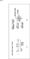
- FIG. 1 illustrates an example of filter processing as prediction processing for predicting an original image for a decoded image from a decoded image encoded and decoded (including local decoding) using a high-order prediction formula It is.
- filter processing is performed using a prediction formula consisting of only first-order terms.
- filter processing is sufficient for minute amplitude portions of pixel values that represent details of the original image degraded by encoding. Sometimes it can not be restored.
- the filtering process using the high-order prediction equation including the high-order term effectively amplifies the luminance (waveform) fluctuation slightly remaining as a portion corresponding to the detail of the original image in the decoded image.
- the original image is accurately restored, including the details of the original image.
- a product of one tap coefficient and (the pixel value of) pixels as one or more prediction taps is a term, and any polynomial is adopted if it is a polynomial including a high-order term be able to. That is, as the high-order prediction equation, for example, a polynomial consisting of only a first-order term and a second-order term, a polynomial consisting of a first-order term and a plurality of higher-order terms of two or more different orders, one or more second-order or more orders A polynomial or the like consisting of higher order terms can be employed.
- y ′ represents a predicted value of (a pixel value of) a corresponding pixel which is a pixel of the original image corresponding to a target pixel among the pixels of the decoded image.
- N1 represents the number of pixels x i as primary taps of the prediction taps, and the number of primary coefficients w i of the tap coefficients.
- w i represents the i-th primary coefficient of the tap coefficients.
- x i represents (the pixel value of) the pixel as the i-th primary tap among the prediction taps.
- N2 represents the number of pixels x j (x k ) as secondary taps of the prediction taps, and the number of secondary coefficients w j, k of the tap coefficients.
- w j, k represents the j ⁇ k second-order coefficient of the tap coefficients.
- the primary tap is represented by x i and the secondary tap is represented by x j and x k , but in the following, depending on the suffix attached to x, There is no particular distinction between primary and secondary taps. That is, for example, be any of primary tap and secondary taps, with x i, primary tap x i and the secondary tap x i, or to as a prediction tap x i, and the like. The same applies to the first-order coefficient w i and the second-order coefficient w j, k which are tap coefficients.
- the high-order prediction formula of Formula (1) is a polynomial which consists only of a first-order term and a second-order term.
- the high-order prediction formula of Expression (1) is a prediction formula as in the case where the number of candidate pixels for the primary tap is N1 and the number of candidate pixels for the secondary tap is N2.
- the number N1 ′ of primary terms of the prediction equation is equal to the number N1 of primary taps.
- the number N2 'of secondary terms of the prediction equation is expressed by equation (2).
- N2 C 2 represents the number of combinations for selecting without overlapping two from the N2.
- Filter processing for applying the high-order prediction formula to the decoded image that is, for example, the product-sum operation of the high-order prediction formula of Equation (1) is performed, and pixel values of corresponding pixels of the original image corresponding to the target pixel of the decoded image.
- a prediction tap is selected from the pixels of the decoded image.
- FIG. 1B shows an example of prediction taps, ie, for example, primary and secondary taps.
- the primary taps are 13 diamond-shaped 13 pixels centered on the target pixel, and the secondary taps are 5 diamond-shaped 5 pixels centered on the target pixel. Therefore, in FIG. 1B, the tap structure of the primary tap and the tap structure of the secondary tap are different. Further, of the 13 pixels which are primary taps, five diamond-shaped five pixels centered on the target pixel are also secondary taps.
- the high-order prediction formula can be applied to currently proposed adaptive loop filters and the like in addition to the ILF of the present technology.
- the candidate pixel for the primary tap and the candidate pixel for the secondary tap, or the tap structure of the primary tap and the tap structure of the secondary tap may be identical or different.
- the tap coefficients of the higher order prediction equation can be volumized and approximated by polynomials.
- the order of the polynomial approximating the tap coefficients can adopt the same value for the primary coefficient and the secondary coefficient among the tap coefficients, or different values Can also be adopted.
- the tap coefficients constituting the higher order prediction equation can be obtained by learning in real time in the encoding device that encodes the image, and can be transmitted to the decoding device that decodes the image.
- tap coefficients constituting the high-order prediction formula can be obtained in advance by off-line learning, and can be preset in the encoding apparatus and the decoding apparatus.
- the tap coefficients constituting the high-order prediction formula can be obtained for each of a plurality of classes.
- the filtering process can be performed using a high-order prediction formula configured by performing class classification of the pixel of interest and using the tap coefficients of the class of the pixel of interest obtained as a result.
- one class is obtained as the number of classes obtained by class classification, it is equivalent to not performing class classification.
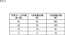
- FIG. 2 is a diagram showing the relationship between the number of prediction taps and the number of tap coefficients in the prediction equation as a whole.
- FIG. 2 shows the relationship between the number N1 of primary taps and the number N1 'of primary coefficients in the prediction formula as a whole, and the relationship between the number N2 of secondary taps and the number N2' of secondary coefficients. ing.
- the number N1 'of primary coefficients matches the number N1 of primary taps, and the number N2' of secondary coefficients exponentially increases relative to the number N2 of secondary taps.
- the filtering process can be performed using a reduction prediction equation that is a high-order prediction equation that is configured by partial terms selected from the prediction equation as a whole.
- a reduction prediction equation that is a high-order prediction equation that is configured by partial terms selected from the prediction equation as a whole.
- FIG. 3 is a diagram for explaining an example of selection of a part of terms from a prediction formula as a whole.
- a case in which all 41 candidate pixels are adopted as prediction taps and a prediction formula of only the first term of the 41 prediction taps is adopted is referred to as a reference case which is used as a reference of comparison.
- the description of the classes is appropriately omitted. That is, in the following, unless otherwise stated, the explanation for the tap coefficient and the like is the explanation for the tap coefficient and the like for each class.
- a high-order prediction formula including all 41 candidate pixels as prediction taps and including quadratic terms of the 41 prediction taps that is, for example, equation (1)
- equation (1) When adopting the whole prediction formula consisting of only the first order term and the second order term, the detail of the original image degraded by the encoding can be restored with high accuracy by the effect of the second order term that is the higher order term compared to the reference case. it can.
- the linear term of the prediction equation is 41 equal to the 41 candidate pixels
- the quadratic term of the prediction equation is 41
- 41 primary terms of the prediction equation are represented by Ax 1 , Ax 2 ,..., Ax 41 , and 861 quadratic terms of the prediction equation are , Ax 1 x 1 , Ax 1 x 2 , ..., Ax 1 x 41 , Ax 2 x 2 , Ax 2 x 3 , ..., Ax 2 x 41 , ..., Ax 41 x 41 Ru.
- the tap coefficient of one class is a linear term
- the total number of tap coefficients, and hence the amount of data, is compared with the reference case, resulting in 902 tap coefficients including 41 tap coefficients as tap coefficients and 861 tap coefficients as second order term tap coefficients. And the coding efficiency is degraded.
- the high-order prediction formula composed of a part of terms selected from the prediction formula as a whole is also referred to as a reduction prediction formula.
- the term (tap coefficients of the prediction equation) in the whole tends to have a large effect of the image quality improvement.
- the term of the pixel (prediction tap) close to the target pixel among the terms of the prediction formula as a whole is adopted as the term of the reduction prediction formula.
- the primary term of the pixel (prediction tap) close to the target pixel is selected and the reduction prediction formula is selected.
- selecting a candidate pixel close to the target pixel instead of all of the 41 candidate pixels as the primary term prediction tap corresponds to selecting a primary term of a pixel close to the target pixel.
- the number of tap coefficients (first-order coefficients) of the first-order term is smaller than 41 in the reference case.
- a quadratic term of a pixel close to a pixel of interest out of 861 quadratic terms of the whole prediction formula using 41 prediction taps is selected, and a quadratic term of the reduction prediction formula is selected.
- selecting a candidate pixel close to the target pixel instead of all of the 41 candidate pixels as the prediction tap of the secondary term corresponds to selecting a secondary term of a pixel close to the target pixel.
- the number of tap coefficients (secondary coefficients) of the quadratic term is smaller than 861 of the reference case.
- the term of the pixel close to the pixel of interest is selected and adopted as the term of the reduction prediction formula.
- the number of tap coefficients of becomes 25 the number of tap coefficients of the quadratic term becomes 15. Therefore, the number of tap coefficients in one class is 40 in total including the tap coefficients of the first-order terms and the second-order terms, reducing the data amount of the tap coefficients to almost the same amount as the reference case and encoding efficiency It can be improved. Furthermore, it is possible to accurately restore the detail of the original image which was difficult to restore by the first order coefficient (tap coefficient of the first order term) by the effect of the second order coefficient (tap coefficient of the second order term) of the reduction prediction formula it can.
- the tap coefficient of one class is set to 40 tap coefficients in total of 25 tap coefficients of the first term and 15 tap coefficients of the second term. It can be said that the use (transmission capacity) of the tap coefficient of the second term is secured by reducing the tap coefficient of the first term within the range of 41 tap coefficients.
- RD cost-based norms and PSNR-based norms for example, in filtering processing using a prediction formula as a whole, RD that exceeds the threshold value is more effective than filtering using a reduction prediction formula where a certain term is deleted from the prediction formula as a whole. If there is an improvement in cost or PSNR, the terms that are entirely deleted from the prediction formula are selected as the terms of the reduction prediction formula.
- a term whose magnitude (absolute value) of the tap coefficient is equal to or greater than a predetermined threshold value is selected as the term of the reduction prediction equation.
- the number of bits necessary to represent a tap coefficient that is, the number of significant digits when the tap coefficient is represented by a binary number (the number of significant digits A term whose) or more is a threshold is selected as a term of the reduction prediction formula.
- R1 linear terms and R2 secondary terms are selected from the whole prediction formula as the terms of the reduction prediction formula, for example, in the rule based on the number of bits necessary to represent tap coefficients
- the linear coefficient is selected from the linear terms of the prediction equation up to the top R1 number of bits necessary to represent the tap coefficients, and the tap coefficients are expressed from the quadratic terms of the prediction equation as a whole.
- the second-order terms up to the top R2 bits are selected. The same applies to RD cost based norms, PSNR based norms, and tap coefficient magnitude based norms.
- the filtering process using the prediction formula in the whole of the selection pattern for selecting the terms from the prediction formula in the whole can do.
- the filter processing using the reduction prediction formula composed of partial terms selected from the prediction formula as a whole the original image degraded by the coding while suppressing the decrease in the coding efficiency Can accurately restore the details of
- FIG. 4 is a diagram for explaining an example of the selection pattern of the quadratic term for selecting the quadratic term of the reduction prediction formula from the quadratic term of the prediction formula as a whole.
- a selection pattern of a first-order term for selecting a first-order term of the reduction prediction formula from the first-order terms of the prediction formula as a whole for example, as a selection pattern of a first-order term for selecting a first-order term of the reduction prediction formula from the first-order terms of the prediction formula as a whole.
- linear terms of pixels as prediction taps a pattern that selects a pixel close to the target pixel, that is, a linear term of 25 rhombus-shaped pixels centering on the target pixel, as a linear term of the reduction prediction formula Will be adopted in a fixed manner.
- the number of tap coefficients (primary coefficients) of the primary term is 25.
- the selection pattern of the quadratic term for example, as shown in B of FIG. 4, of the quadratic terms of the pixels as 41 diamond-shaped prediction taps, five diamond-shaped pixels centering on the pixel of interest
- a first selection pattern may be adopted in which the quadratic term of is selected as the quadratic term of the reduction prediction equation.
- the selection pattern of the quadratic term for example, as shown in C of FIG. 4, of the quadratic terms of the pixels as 41 diamond-shaped prediction taps, 13 of the diamond-like form centering on the target pixel
- a second selection pattern can be adopted in which the quadratic term of the pixel of is selected as the quadratic term of the reduction prediction equation.
- the quadratic term of one pixel of the target pixel among the quadratic terms of the pixels as 41 rhombus-shaped prediction taps is reduced
- the third selection pattern to be selected as the quadratic term of the prediction equation can be adopted.
- the total number of quadratic terms of one pixel is one, which is only a square term of (the pixel value of) that one pixel.
- the selection pattern as described above can be fixedly adopted.
- the selection of the second-order term of the reduction prediction equation among the entire selection pattern for selecting the second-order term from the prediction equation, the data of PSNR reduction amount and tap coefficient for filter processing using the entire prediction equation.
- Selection patterns that balance the amount of reduction and selection patterns that optimize (the index of) coding efficiency such as RD cost are selected as second-order selection patterns (hereinafter also referred to as adopted patterns) that are adopted in the reduction prediction formula According to the selection pattern, it is possible to select a quadratic term to be adopted in the reduction prediction formula.
- a plurality of selection patterns such as the first to third selection patterns are selected as selection patterns for selecting the quadratic term from the prediction formula as a whole.
- a selection pattern or code for balancing the reduction amount of PSNR and the reduction amount of tap coefficient data for filter processing using a prediction formula as a whole among a plurality of selection patterns prepared in advance and prepared beforehand The selection pattern that makes the conversion efficiency the best can be determined as the adopted pattern, and the quadratic term to be adopted in the reduction prediction formula can be selected according to the adopted pattern (the selected pattern determined).
- the selection pattern to be selected is fixed for each of the primary term and the secondary term, and the encoding apparatus and the decoding apparatus select according to the fixed selection pattern.
- the filtering process can be performed using a reduction prediction equation consisting of the primary term and the secondary term.
- a plurality of selection patterns are prepared in advance as selection patterns for selecting the primary term and the secondary term, and each selection pattern and its selection pattern are It is possible to associate coding information such as QP of an image that tends to improve coding efficiency when adopted. Then, in the encoding device and the decoding device, in accordance with the encoded information such as the QP of the decoded image (the original image for it), the selected pattern associated with the encoded information is determined as the adopted pattern, and the adopted pattern According to the first term and the second term to be adopted in the reduction prediction formula can be selected.
- a plurality of selection patterns can be prepared in advance as selection patterns for selecting the primary term and the secondary term. Then, in the encoding apparatus, for example, among the plurality of selection patterns, the selection pattern that makes the coding efficiency the best is determined as the adopted pattern, and the first order term and the second order term adopted in the reduction prediction formula according to the adopted pattern. Can be selected. Furthermore, in this case, the encoding apparatus transmits selection information representing the adopted pattern (selected pattern determined to) to the decoding apparatus, and the decoding apparatus reduces the information according to the adopted pattern represented by the selection information from the encoding apparatus The first order term and the second order term to be employed in the prediction equation can be selected.
- a method of preparing a plurality of selection patterns and determining an adopted pattern (a selection pattern to be taken) from among the plurality of selection patterns according to encoding information and encoding efficiency is a reduction.
- the present invention can also be applied to the case where a plurality of selection patterns are prepared for only the secondary term, with the selection pattern of the primary term of the prediction equation fixed.
- FIG. 5 is a diagram for explaining another example of the selection pattern of the quadratic term for selecting the quadratic term of the reduction prediction formula from the quadratic term of the prediction formula as a whole.
- a circle represents a pixel as a prediction tap.
- a black dot in a circle represents (the quadratic term of) the square of a pixel as a prediction tap represented by the circle, and a line connecting two different circles is a prediction represented by each of the two circles. This represents (the quadratic term of) the product of pixels as a tap.
- the selection pattern of the secondary term is shown in FIG.
- five second-order terms of squares of five five-pixel shaped rhombuses and ten second-order terms of (a product of ten combinations of two arbitrary pixels of five pixels of rhombus-shaped form) A pattern may be employed which selects a total of 15 quadratic terms.
- the number of tap coefficients (one class) is 40 in total of 25 primary coefficients and 15 secondary term tap coefficients (secondary coefficients).
- the selection pattern of the quadratic term as shown in B of FIG. 5, five quadratic terms of the square shape of five pixels of the rhombus shape as secondary taps, the attention pixel, and other four pixels A pattern may be employed which selects a total of nine quadratic terms, with four quadratic terms of the product with each.
- the number of tap coefficients is 34 in total of the 25 primary coefficients and the tap coefficients of 9 quadratic terms.
- one quadratic term of the square of the pixel of interest among the five diamond-shaped five pixels as the secondary tap and the pixel of interest It is possible to adopt a pattern which selects a total of five quadratic terms with four quadratic terms of the product of each of the other four pixels.
- the number of tap coefficients is 30 in total of the 25 primary coefficients and the tap coefficients of the 5 secondary terms.
- the selection pattern of the quadratic term as shown in D of FIG. 5, it is possible to adopt a pattern for selecting five quadratic terms of the square of five pixels of the rhombus shape as square taps. it can.
- the number of tap coefficients is 30 in total of the 25 primary coefficients and the tap coefficients of the 5 secondary terms.
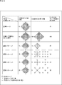
- FIG. 6 is a diagram for explaining still another example of the selection pattern of the quadratic term for selecting the quadratic term of the reduction prediction formula from the quadratic term of the prediction formula as a whole.
- FIG. 6 four selection patterns 1, 2, 3, 4 are shown as the selection terms of the secondary term.
- FIG. 6 shows the tap coefficients of the reference case and the tap coefficients of the whole prediction equation when all 41 candidate pixels of the reference case are used as the primary tap and the secondary tap.
- the number of tap coefficients (of one class) may be 41 for the first-order coefficients, it is obtained by the filter processing using a prediction formula composed of the 41 first-order coefficients Filter image, it may not be possible to sufficiently restore the details (small amplitude portion) of the original image.
- the filtering process using the prediction equation as a whole it is possible to sufficiently restore the detail of the original image in the filtered image obtained by the filtering process.
- the number of tap coefficients is 902 in total of the primary coefficient and the secondary coefficient, and the data amount of the tap coefficients is large.
- a linear term of 25 (candidate) pixels in a rhombus shape centered on the target pixel among the 41 candidate pixels in the reference case is selected as a linear term of the reduction prediction formula . Therefore, in the selection patterns 1 to 4, the number of tap coefficients (primary coefficients) of the primary term is 25.
- the number of tap coefficients is 40 in total of the primary coefficients of the 25 primary terms and the secondary coefficients of the 15 secondary terms. Less than the reference case.
- the filtering process using the reduction prediction formula of the selection pattern 1 in the filtered image obtained by the filtering process, the detail of the original image can be sufficiently restored by the effect of the quadratic term.
- the filtering process using the prediction formula can be almost performed with a small quadratic term, that is, a quadratic coefficient of a small data amount. It is possible to maintain the restoration performance of equal (close) details.
- nine square pixels in the form of a square with the pixel of interest and eight pixels adjacent to the pixel of interest are employed as secondary taps. Then, a total of nine quadratic terms of one square of the square of the pixel of interest out of the nine pixels as secondary taps and eight quadratic terms of the product of the pixel of interest and each of the other eight pixels.
- a quadratic term or nine quadratic terms of squares of 9 pixels as secondary taps are selected as quadratic terms of the reduction prediction formula.
- the number of tap coefficients is 34 in total of the primary coefficients of the 25 primary terms and the secondary coefficients of the 9 secondary terms. , Which is less than the reference case and the selection pattern 1.
- the filtering process using the reduction prediction equation of the selection pattern 2 in the filtered image obtained by the filtering process, the detail of the original image can be sufficiently restored by the effect of the quadratic term.
- the use of the secondary term (the tap coefficient) is secured by making the (first tap coefficient) of the first order term smaller than that of the reference case. Furthermore, by selecting the quadratic term of the pixel close to the pixel of interest as the quadratic term of the reduction prediction formula, the filtering process using the prediction formula can be almost performed with a small quadratic term, that is, a quadratic coefficient of a small data amount. The same detail restoration performance can be maintained.
- the selection pattern 2 is particularly effective when the original image to be restored is a pattern that spreads in the vertical and horizontal directions (having directivity in the vertical and horizontal directions).
- the selection pattern 3 five cross-shaped pixels of the pixel of interest and four pixels adjacent to the pixel of interest are adopted as secondary taps. Then, a total of five secondary terms of one square of the square of the pixel of interest out of the five pixels as secondary taps and four quadratic terms of the product of the pixel of interest and each of the other four pixels A quadratic term or five quadratic terms of the square of five pixels as secondary taps are selected as quadratic terms of the reduction prediction formula.
- the number of tap coefficients is 30 in total of the primary coefficients of the 25 primary terms and the secondary coefficients of the 5 secondary terms. , And less than the reference case, and also the selection patterns 1 and 2.
- the filtering process using the reduction prediction formula of the selection pattern 3 in the filtered image obtained by the filtering process, the detail of the original image can be sufficiently restored by the effect of the quadratic term.
- the use of the secondary term (the tap coefficient) is secured by making the primary term (the tap coefficient thereof) smaller than that of the reference case. Furthermore, by selecting the quadratic term of the pixel close to the pixel of interest as the quadratic term of the reduction prediction formula, the filtering process using the prediction formula can be almost performed with a small quadratic term, that is, a quadratic coefficient of a small data amount. The same detail restoration performance can be maintained.
- the selection pattern 3 is particularly effective when the original image to be restored is a pattern having vertical and horizontal directivity.
- the selection pattern 4 five X-shaped pixels of the pixel of interest and four pixels adjacent to the target pixel are adopted as secondary taps. Then, a total of five secondary terms of one square of the square of the pixel of interest out of the five pixels as secondary taps and four quadratic terms of the product of the pixel of interest and each of the other four pixels A quadratic term or five quadratic terms of the square of five pixels as secondary taps are selected as quadratic terms of the reduction prediction formula.
- the number of tap coefficients is 30 in total of the primary coefficients of the 25 primary terms and the secondary coefficients of the 5 secondary terms. , And less than the reference case, and also the selection patterns 1 and 2.
- the filtering process using the reduction prediction formula of the selection pattern 4 in the filtered image obtained by the filtering process, the detail of the original image can be sufficiently restored by the effect of the quadratic term.
- the use of the secondary term (the tap coefficient) is secured by making the primary term (the tap coefficient thereof) smaller than that of the reference case. Furthermore, by selecting the quadratic term of the pixel close to the pixel of interest as the quadratic term of the reduction prediction formula, the filtering process using the prediction formula can be almost performed with a small quadratic term, that is, a quadratic coefficient of a small data amount. The same detail restoration performance can be maintained.
- the selection pattern 4 is particularly effective when the original image to be restored is a pattern having diagonal directivity.
- a plurality of selection patterns for selecting the quadratic terms of pixels in the vicinity of the target pixel that easily contributes to the image quality are prepared in advance. It is possible to determine the selection pattern to be the second order selection pattern (adopted pattern) adopted in the reduction prediction formula, and transmit the selection information representing the selected pattern determined to the adopted pattern.
- the determination of an adopted pattern from among a plurality of selection patterns can be performed in frame units, sequence units, or any other unit.
- the determination of the adoption pattern it is possible to determine one selection pattern as the adoption pattern in common to all classes, or to select the one selection pattern as the adoption pattern for each class.
- FIG. 7 is a diagram for explaining a representation form of tap coefficients constituting the high-order prediction formula.
- FIG. 7 shows tap coefficients (first-order coefficients) constituting high-order prediction formula (reduction prediction formula) of selected pattern 1 using images of different properties (patterns) as learning images for learning tap coefficients.
- the maximum value and the minimum value of the values of tap coefficients obtained by performing learning for obtaining the coefficient and the secondary coefficient) are shown.
- the horizontal axis represents the order of tap coefficients
- the vertical axis represents values of tap coefficients
- serial numbers from 1 are attached in order to the 25 primary coefficients and the 15 secondary coefficients that make up the reduction prediction equation of the selection pattern 1.
- the tap coefficient is expressed by bits of a predetermined number of bits such as 8 bits.
- formats such as fixed point and floating point can be adopted, but here, in order to simplify the explanation, fixed point will be considered.
- the fixed-point representation form it is possible to adopt a representation form in which the number of bits of the integer part and the fraction part is various bits depending on the position of the decimal point in the bit string of a predetermined number of bits.
- the representation form of the tap coefficient can be determined, for example, for each of the orders of the terms constituting the high-order prediction formula (reduction prediction formula).
- the tap coefficients (the first-order coefficients) of the first-order terms have a tendency that the values largely fluctuate. Therefore, with respect to the primary coefficient, an expression form in which the number of bits is allocated to the integer part can be determined as the expression form of the primary coefficient. The number of bits to be allocated to the integer part can be determined according to the absolute value of the primary coefficient so that the accuracy of the primary coefficient can be secured.
- the tap coefficient of the quadratic term has a tendency that the absolute value of the value is small. Therefore, with regard to the secondary coefficient, an expression form in which the number of bits is allocated to the decimal part can be determined as the expression form of the secondary coefficient. The number of bits to be allocated to the fractional part can be determined according to the absolute value of the secondary coefficient so that the accuracy of the secondary coefficient can be secured.
- the secondary coefficient tends to take the value of a decimal with a large number of digits less than 1, it is possible to adopt a bit string of variable number of bits as an expression form of the tap coefficient.
- the representation format can be determined to be a bit string having a larger number of bits than the linear term.
- the position of the decimal point of the fixed-length bit string representing the tap coefficient is the tendency of the maximum value and the minimum value of the tap coefficient It can be decided beforehand at a fixed position according to
- the encoding apparatus transmits the tap coefficients in a bit string representing the tap coefficients in an expression format in which the position of the decimal point is determined in advance at a fixed position. Then, the decoding device treats the bit string representing the tap coefficient of each order term (linear term and quadratic term) from the encoding device as a bit string of expression format in which the position of the decimal point is determined in advance at a fixed position. Processing, that is, calculation of a high-order prediction formula (reduction prediction formula) is performed.
- the representation form is determined according to the magnitude of the absolute value of the primary coefficient and the secondary coefficient for each frame, sequence, etc. That is, the position of the decimal point of the fixed length bit string representing the tap coefficient can be determined according to the tendency of the maximum value and the minimum value of the tap coefficient.
- the encoding apparatus transmits the primary coefficient and the secondary coefficient in the expression format of the determined decimal point position, and transmits format information representing the expression format for each of the primary coefficient and the secondary coefficient.
- the decoding device specifies the representation form of the bit string representing the tap coefficient of each order term (primary term and secondary term) from the encoding device from the format information from the encoding device, and the bit string representing the tap coefficient , And treating as a bit string of the expression format specified from the format information, the filter processing, that is, the calculation of the high-order prediction equation (reduction prediction equation) is performed.
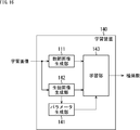
- FIG. 8 is a block diagram showing an outline of an embodiment of an image processing system to which the present technology is applied.
- the image processing system includes an encoding device 11 and a decoding device 12.
- the encoding device 11 includes an encoding unit 21, a local decoding unit 23, and a filter unit 24.
- the encoding unit 21 is supplied with the original image (data) that is the image to be encoded, and the filter image from the filter unit 24.
- the encoding unit 21 (predictive) encodes the original image using the filter image from the filter unit 24, and supplies encoded data obtained by the encoding to the local decoding unit 23.
- the encoding unit 21 subtracts the predicted image of the original image obtained by performing motion compensation of the filter image from the filter unit 24 from the original image, and encodes the residual obtained as a result.
- the encoding unit 21 generates and transmits (transmits) an encoded bit stream including the encoded data and the filter information supplied from the filter unit 24.
- the filter information includes, as necessary, tap coefficients constituting the high-order prediction formula (reduction prediction formula), and further, selection information and format information.
- the encoded bit stream generated by the encoding unit 21 is a bit stream including tap coefficients, selection information, and format information as needed in addition to the encoded data.
- the local decoding unit 23 is supplied with the encoded data from the encoding unit 21, and is also supplied with the filter image from the filter unit 24.
- the local decoding unit 23 performs local decoding of the encoded data from the encoding unit 21 using the filter image from the filter unit 24, and supplies the (local) decoded image obtained as a result to the filter unit 24.
- the local decoding unit 23 decodes the encoded data from the encoding unit 21 into a residual, and performs motion compensation of the filter image from the filter unit 24 on the residual to obtain a predicted image of the original image obtained.
- the addition generates a decoded image obtained by decoding the original image.
- the filter unit 24 performs a filter process of applying a high-order prediction formula (reduction prediction formula) to the decoded image from the local decoding unit 23, generates a filter image, and supplies the filter image to the encoding unit 21 and the local decoding unit 23. Do.
- the filter unit 24 when performing the filter processing, performs learning for obtaining tap coefficients that constitute a high-order prediction formula (reduction prediction formula) as necessary, and determines an adopted pattern and an expression form of the tap coefficients. Do. Then, the filter unit 24 supplies the tap coefficient, the selection information indicating the adopted pattern, and the format information indicating the expression format of the tap coefficient to the encoding unit 21 as filter information related to the filter process.
- the decoding device 12 includes a parsing unit 31, a decoding unit 32, and a filter unit 33.
- the parsing unit 31 receives and parses the encoded bit stream transmitted by the encoding device 11, extracts (gets) filter information included in the encoded bit stream, and supplies the filter information to the filter unit 33. Furthermore, the parsing unit 31 supplies the encoded data included in the encoded bit stream to the decoding unit 32.
- the decoding unit 32 is supplied with the encoded data from the parsing unit 31 and also with the filter image from the filter unit 33.
- the decoding unit 32 decodes the encoded data from the parsing unit 31 using the filter image from the filter unit 33, and supplies the decoded image obtained as a result to the filter unit 33.
- the decoding unit 32 decodes the encoded data from the perspective unit 31 into a residual, and performs motion compensation of the filter image from the filter unit 33 on the residual.
- a predicted image of the original image is added to generate a decoded image obtained by decoding the original image.
- the filter unit 33 performs filter processing to apply a high-order prediction formula (reduction prediction formula) to the decoded image from the decoder 32, generates a filter image, and supplies the filter image to the decoder 32. Do.
- the filter unit 33 uses the filter information from the perspective unit 31 as necessary when performing the filter process. Further, the filter unit 33 supplies the filter image obtained (generated) by the filter process to the decoding unit 32, and outputs the original image as a restored image.
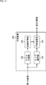
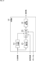
- FIG. 9 is a block diagram showing an outline of a configuration example of the filter units 24 and 33 of FIG.
- the filter unit 24 includes a class classification unit 41, a learning unit 42, a DB (database) 43, a determination unit 44, a DB 45, and a prediction unit 46.
- the original image is supplied to the filter unit 24 as well as the decoded image from the local decoding unit 23 (FIG. 8).
- the decoded image is supplied to the class classification unit 41, the learning unit 42, the determination unit 44, and the prediction unit 46, and the original image is supplied to the learning unit 42 and the determination unit 44.
- the class classification unit 41 sequentially selects the pixels of the decoded image supplied thereto as the pixel of interest. Furthermore, the class classification unit 41 classifies the pixel of interest, and supplies the class of the pixel of interest obtained as a result to the learning unit 42, the determination unit 44, and the prediction unit 46.
- the learning unit 42 uses the original image and the decoded image supplied thereto as a learning image for learning for determining tap coefficients, and selects a plurality of selection patterns, ie, for example, each of the selection patterns 1 to 4 in FIG. A learning is performed for each class to obtain primary and secondary coefficients that are tap coefficients that constitute a pattern reduction prediction equation.
- the learning unit 42 performs learning for each frame (picture) of the original image and the decoded image, and supplies, to the DB 43, tap coefficients for each class obtained for each of a plurality of selection patterns by the learning.
- the DB 43 temporarily stores the tap coefficient for each class for each of the plurality of selection patterns supplied from the learning unit 42.
- the determination unit 44 expresses an expression form (hereinafter also referred to as a best expression form) that optimizes the coding efficiency for each of the primary coefficient and secondary coefficient that are tap coefficients for each class stored in the DB 43. To determine).
- an expression form hereinafter also referred to as a best expression form
- the determination unit 44 adopts a selection pattern that optimizes the coding efficiency when filtering processing is performed to apply a reduction prediction equation including tap coefficients in the best representation format to each selection pattern.
- the pattern is determined (selected), and the tap coefficient for each class for the adopted pattern (selected pattern determined) is supplied to the DB 45.
- the determination unit 44 outputs form information representing the best expression form of each of the primary coefficient and secondary coefficient which are tap coefficients for the adopted pattern, and selection information representing the adopted pattern.
- the format information and the selection information output from the determination unit 44 are supplied to the prediction unit 46 and included in the encoded bit stream as filter information in the encoding unit 21 (FIG. 8) and transmitted to the decoding device 12 Ru.
- the determination unit 44 applies, to the decoded image, a reduction prediction equation configured of tap coefficients for each class stored in the DB 43 for each selection pattern, as needed.
- the same filtering process as that of the original image is performed, and the original image is used together with the resulting filtered image to determine the coding efficiency such as the RD cost.
- the DB 45 temporarily stores the tap coefficient for each class for the adoption pattern supplied from the determination unit 44.
- the tap coefficients for each class for the adopted pattern stored in the DB 45 are included in the encoded bit stream as filter information in the encoding unit 21 (FIG. 8) and transmitted to the decoding device 12.
- the prediction unit 46 applies, to the decoded image, a reduction prediction equation including tap coefficients of the class of the pixel of interest from the class classification unit 41 among tap coefficients for each class for the adopted pattern stored in the DB 45.
- Filter processing as prediction processing (high-order prediction expression using reduction prediction expression, so to speak, high-order prediction processing), and the filter image obtained as a result thereof is encoded by the encoding unit 21 and the local decoding unit 23 (FIG. Supply to 8).
- the prediction unit 46 specifies the expression format (best expression format) of the tap coefficient (each of the primary coefficient and the secondary coefficient) from the format information from the determination unit 44. Further, the prediction unit 46 specifies the adopted pattern of the reduction polynomial from the selection information from the determination unit 44, and from the adopted pattern, the term constituting the reduction polynomial, and as a prediction tap used for the calculation of the reduction polynomial. Identify pixels of the decoded image.
- the prediction unit 46 performs filter processing for applying the reduction prediction formula of the adopted pattern, which is composed of the tap coefficients of the class of the target pixel in the best representation format, to the decoded image, that is, prediction as calculation of the reduction prediction formula.
- a product-sum operation is performed on (the pixel values of) the pixels of the decoded image as taps and the tap coefficients to obtain a filter image.
- the calculation according to the best expression form of the tap coefficient and the expression form of the pixel value of the decoded image is performed. That is, for example, when the pixel value and tap coefficient of the decoded image are represented by 10 bits, the pixel value of the decoded image is an integer type, and the tap coefficient is fixed point having a 9-bit fractional part, decoding in filter processing
- the product of the bit string representing the pixel value of the decoded image and the bit string representing the tap coefficient is determined, and then the bit string representing the product is shifted to the right by 9 bits , Divided by 512.
- the filter unit 33 includes a classification unit 51 and a prediction unit 52.
- Filter information is supplied to the filter unit 33 from the perspective unit 31 (FIG. 8), and a decoded image is supplied from the decoding unit 32 (FIG. 8).
- the class classification section 51 sequentially selects the pixels of the decoded image supplied thereto as the pixel of interest. Furthermore, the class classification unit 51 classifies the pixel of interest and supplies the class of the pixel of interest obtained as a result to the prediction unit 52.
- the prediction unit 52 applies, to the decoded image, a reduction prediction equation including tap coefficients of the class of the pixel of interest from the class classification unit 51 among tap coefficients for each class for the adopted pattern included in the filter information. Then, filter processing as prediction processing is performed, and the filter image obtained as a result is supplied to the decoding unit 32 (FIG. 8).
- the prediction unit 52 specifies the expression format (best expression format) of the tap coefficient (each of the primary coefficient and the secondary coefficient) from the format information included in the filter information. Further, the prediction unit 52 specifies the adopted pattern of the reduction polynomial from the selection information included in the filter information, and from the adopted pattern, the term constituting the reduction polynomial, and as a prediction tap used for the calculation of the reduction polynomial. Identify pixels of the decoded image.
- the prediction unit 52 performs filter processing for applying the reduction prediction formula of the adopted pattern, which is composed of the tap coefficients of the class of the target pixel in the best expression format, to the decoded image, that is, prediction as calculation of the reduction prediction formula.
- a product-sum operation is performed on (the pixel values of) the pixels of the decoded image as taps and the tap coefficients to obtain a filter image.
- FIG. 10 is a flowchart for explaining the outline of the encoding process of the encoding device 11 of FIG.
- the process according to the flowchart of FIG. 10 is performed, for example, on a frame basis.
- step S11 the encoding unit 21 (FIG. 8) (predictive) encodes the original image using the filter image from the filter unit 24, and uses the local decoding unit 23 for the encoded data obtained by the encoding. After supplying, the process proceeds to step S12.
- step S12 the local decoding unit 23 performs local decoding of the encoded data from the encoding unit 21 using the filter image from the filter unit 24, and the (locally) decoded image obtained as a result thereof is processed by the filter unit 24. , And the process proceeds to step S13.
- step S13 in the filter unit 24, the class classification unit 41 (FIG. 9) sequentially selects the pixels of the decoded image from the local decoding unit 23 as the pixel of interest. Furthermore, the class classification unit 41 classifies the pixel of interest, supplies the class of the pixel of interest obtained as a result to the learning unit 42, the determination unit 44, and the prediction unit 46, and the process proceeds to step S14. move on.
- step S14 the learning unit 42 uses one frame of the decoded image from the local decoding unit 23 and one frame of the original image for the frame of the decoded image as a learning image for learning for obtaining tap coefficients, and a plurality of selection patterns For each class, learning is performed for each class to obtain a primary coefficient and a secondary coefficient that are tap coefficients constituting the reduction prediction formula of the selected pattern.
- the learning unit 42 stores the tap coefficient for each class obtained for each of the plurality of selection patterns by learning in the DB 43, and the process proceeds from step S14 to step S15.
- step S15 the determination unit 44 is, for each selected pattern, a best expression that is an expression format that optimizes the coding efficiency for each of the primary coefficient and the secondary coefficient that are tap coefficients for each class stored in the DB 43.
- the format is determined, and the process proceeds to step S16.
- step S16 the determination unit 44 selects, for each selection pattern, a selection pattern that maximizes the coding efficiency when the reduction prediction formula configured of tap coefficients in the best representation format is applied to the decoded image. Is selected (selected) as an adopted pattern, and the tap coefficient for each class for the adopted pattern (selected pattern determined) is stored in the DB 45. The tap coefficients for each class for the adopted pattern stored in the DB 45 are supplied to the encoding unit 21 as filter information.
- the determination unit 44 uses, as filter information, the format information indicating the best expression format of each of the primary coefficient and the secondary coefficient that are tap coefficients for the adopted pattern, and the selection information indicating the adopted pattern. And the prediction unit 46, and the process proceeds from step S16 to step S17.
- step S17 of the tap coefficients for each class of the adopted pattern stored in the DB 45, the prediction unit 46 locally uses a reduction prediction formula configured of tap coefficients of the class of the pixel of interest from the class classification unit 41. It applies to the decoded image from the decoding unit 23 and performs filter processing as prediction processing.
- the prediction unit 46 specifies the expression format (best expression format) of the tap coefficient (each of the primary coefficient and the secondary coefficient) from the format information from the determination unit 44. Further, the prediction unit 46 specifies the adopted pattern of the reduction polynomial from the selection information from the determination unit 44.
- the prediction unit 46 performs filter processing for applying a reduction prediction formula of the adopted pattern, which is composed of tap coefficients of the class of the target pixel in the best expression format, to the decoded image, and obtains a filter image.
- the prediction unit 46 supplies the filter image obtained as a result of the filtering process to the encoding unit 21 and the local decoding unit 23, and the process proceeds from step S17 to step S18.
- the filter image supplied from the prediction unit 46 to the encoding unit 21 and the local decoding unit 23 in step S17 is used, for example, in the processes of steps S11 and S12 performed on the next frame of the decoded image.
- step S18 the encoding unit 21 generates and transmits an encoded bit stream including encoded data and filter information from the filter unit 24, that is, selection information, format information, and tap coefficients for each class. Do.
- one selection pattern may be determined as the adoption pattern in common to all classes, or one selection pattern may be determined as the adoption pattern for each class. Can.
- the number of selection information and format information is the number (total number) times of the number of classes in the case where one selection pattern is determined as the adopted pattern in common to all classes.
- the prediction unit 46 specifies the tap coefficient representation form (best representation form) for each class in the filtering process performed in step S17. And identifying the adopted pattern of the reduction polynomial, and from the adopted pattern, identify the terms constituting the reduction polynomial and, consequently, the pixels of the decoded image as the prediction taps used for the calculation of the reduction polynomial.
- FIG. 11 is a flowchart illustrating an outline of the decoding process of the decoding device 12 of FIG.
- the process according to the flowchart of FIG. 11 is performed, for example, in units of frames, similarly to the encoding process of FIG.
- step S21 the parsing unit 31 (FIG. 8) extracts the filter information included in the encoded bit stream by receiving the encoded bit stream transmitted from the encoding device 11 and performing parsing. ) To the filter unit 33. Furthermore, the parsing unit 31 supplies the encoded data included in the encoded bit stream to the decoding unit 32, and the process proceeds from step S21 to step S22.
- step S22 the decoding unit 32 decodes the encoded data from the perspective unit 31 using the filter image from the filter unit 33, supplies the decoded image obtained as a result to the filter unit 33, and performs processing. The process proceeds to step S23.
- step S23 in the filter unit 33, the class classification unit 51 (FIG. 9) sequentially selects the pixels of the decoded image from the decoding unit 32 as the pixel of interest. Furthermore, the class classification unit 51 classifies the pixel of interest, supplies the class of the pixel of interest obtained as a result to the prediction unit 52, and the process proceeds to step S24.
- step S24 of the tap coefficients for each class of the adopted pattern included in the filter information from the perspective unit 31, the prediction unit 52 is configured to be configured with the tap coefficients of the class of the pixel of interest from the class classification unit 51.
- the prediction equation is applied to the decoded image from the decoding unit 32, and filter processing as prediction processing is performed to obtain (generate) a filter image.
- the prediction unit 52 specifies the expression format (best expression format) of the tap coefficient (each of the primary coefficient and the secondary coefficient) from the format information included in the filter information. Further, the prediction unit 52 specifies an adopted pattern of the reduction polynomial from the selection information included in the filter information.
- the prediction unit 52 performs filter processing for applying a reduction prediction formula of the adopted pattern, which is composed of tap coefficients of the class of the target pixel in the best expression format, to the decoded image, and obtains a filter image.
- the filter image obtained as a result of the filtering process in the prediction unit 52 is supplied to the decoding unit 32 (FIG. 8) and is output as a restored image obtained by restoring the original image.
- the filter image supplied from the prediction unit 52 to the decoding unit 32 in step S24 is used, for example, in the process of step S22 performed on the next frame of the decoded image.
- Class classification prediction processing for an image performs class classification using a first image which is an image of a class classification prediction processing target, and tap coefficients of the class obtained as a result of the class classification and the first image Filter processing as prediction processing using a prediction formula that performs product-sum operation with (the pixel value of) pixels of the pixel (filtering processing), and the prediction value of the second image is determined (generated) by such filter processing .
- the first image is a decoded image (including a local decoded image)
- the second image is an original image.
- FIG. 12 is a block diagram showing a first configuration example of a prediction device that performs class classification prediction processing.
- the tap coefficient of the class obtained by classifying the target pixel of interest in the first image into any one of a plurality of classes, and prediction with respect to the target pixel The product-sum operation as the calculation of the prediction formula using the pixel value of the first image pixel selected as the tap determines the predicted value of the pixel value of the corresponding pixel of the second image corresponding to the target pixel .
- FIG. 12 shows a configuration example of a prediction device that performs class classification prediction processing.
- the prediction device 100 includes a tap selection unit 101, a class classification unit 102, a coefficient acquisition unit 103, and a prediction calculation unit 104.
- the prediction apparatus 100 is supplied with the first image.
- the first image supplied to the prediction device 100 is supplied to the tap selection unit 101 and the class classification unit 102.
- the tap selection unit 101 sequentially selects the pixels forming the first image as the target pixel. Furthermore, the tap selection unit 101 predicts some of (pixel values of) pixels constituting the first image used to predict (the pixel value of) the corresponding pixel of the second image corresponding to the target pixel. Select as a tap.
- the tap selection unit 101 selects, as prediction taps, a plurality of pixels of the first image located at a position spatially or temporally close to the position of space-time of the pixel of interest. Supply.
- the class classification unit 102 classifies the pixel of interest into one of several classes according to a certain rule, and supplies the class of the pixel of interest obtained as a result to the coefficient acquisition unit 103. .
- the class classification unit 102 selects, for example, some of (the pixel values of) the pixels constituting the first image used to perform the class classification for the pixel of interest as class taps. For example, the class classification unit 102 selects a class tap in the same manner as the tap selection unit 101 selects a prediction tap.
- the prediction tap and the class tap may have the same tap structure, or may have different tap structures.
- the class classification unit 102 classifies the pixel of interest using, for example, a class tap, and supplies the class of the pixel of interest obtained as a result to the coefficient acquisition unit 103.
- the class classification unit 102 obtains the image feature amount of the pixel of interest using a class tap. Furthermore, the class classification unit 102 classifies the pixel of interest according to the image feature amount of the pixel of interest, and supplies the class obtained as a result to the coefficient acquisition unit 103.
- ADRC Adaptive Dynamic Range Coding
- ADRC code represents a waveform pattern as an image feature of a small area including a target pixel.
- the pixel value of each pixel as a class tap is requantized into L bits. That is, the pixel value of each pixel as a class tap, the minimum value MIN is subtracted, and the subtracted value is divided by DR / 2 L (requantization). Then, a bit string obtained by arranging the pixel values of each pixel of L bits as class taps, which are obtained as described above, in a predetermined order is output as an ADRC code.
- the pixel value of each pixel as the class tap is divided by the average value of the maximum value MAX and the minimum value MIN (rounded down to the decimal point), As a result, the pixel value of each pixel is made 1 bit (binarized). Then, a bit string in which the 1-bit pixel values are arranged in a predetermined order is output as an ADRC code.
- the value represented by such an ADRC code represents a class.
- DiffMax Dynamic Range
- DR Dynamic Range
- classification can be performed using the quantization parameter QP of the pixel of interest and other coding information. That is, class classification can be performed by, for example, threshold processing of coding information.
- the coefficient acquisition unit 103 stores the tap coefficient for each class obtained by learning, and further acquires the tap coefficient of the class of the target pixel supplied from the class classification unit 102 among the stored tap coefficients. Furthermore, the coefficient acquisition unit 103 supplies the tap coefficient of the class of the pixel of interest to the prediction calculation unit 104.
- the prediction calculation unit 104 uses the prediction tap from the tap selection unit 101 and the tap coefficient supplied from the coefficient acquisition unit 103 to select the pixel value of the pixel (corresponding pixel) of the second image corresponding to the target pixel. Filter processing is performed as prediction processing which is product-sum operation of a prediction formula for obtaining a prediction value of a true value. Thereby, the prediction calculation unit 104 obtains (predicted value of) the pixel value of the corresponding pixel, that is, (predicted value of) the pixel value of the pixel constituting the second image, and outputs it.
- FIG. 13 is a block diagram showing a configuration example of a learning device that performs learning of tap coefficients stored in the coefficient acquisition unit 103.
- the decoded image is adopted as the first image
- the original image for the decoded image is adopted as the second image
- prediction taps and tap coefficients selected from the first image It is assumed that the pixel value of the pixel of the original image as the second image (hereinafter, also referred to as a second pixel) is predicted by the filter process as the prediction process which is the product-sum operation of the prediction equation consisting of only the first order terms.
- the pixel value y of the second pixel as the corresponding pixel of the second image corresponding to the target pixel is obtained according to the following prediction equation.
- x n is the pixel of the n-th of the first image as a prediction tap of the pixel of interest (hereinafter, also referred to as a first pixel) represents the pixel values of
- w n is the n th Represents the tap coefficient (n-th tap coefficient) of the first-order term of.
- the prediction equation of equation (3) is composed of N terms (first order terms).
- the pixel value y of the second pixel is determined not by the prediction formula consisting only of the first-order term of Formula (3) but by a high-order prediction formula including second-order or higher order terms.
- x n, k represents the n-th 1st pixel as a prediction tap with respect to the 2nd pixel of the k-th sample as a corresponding
- the tap coefficient w n for which the prediction error e k in equation (5) (or equation (4)) is 0 is optimal for predicting the second pixel, but for all the second pixels, Determining such tap coefficients w n is generally difficult.
- the optimum tap coefficient w n is the sum E of square errors represented by the following equation It can be determined by minimizing statistical error).
- K is a second pixel y k as the corresponding pixel
- the first pixel x 1, k of the prediction tap for the second pixel y k, x 2, k, ⁇ .., X N, k represents the number of samples in the set (the number of samples for learning).
- Equation (7) The minimum value of the sum E of square errors of Equation (6) (minimum value), as shown in Equation (7), given a material obtained by partially differentiating the sum E with the tap coefficient w n by w n to 0.
- equation (9) can be expressed by the normal equation shown in the equation (10).
- Equation (10) can be solved for the tap coefficient w n by using, for example, the sweep method (Gauss-Jordan elimination method) or the like.
- FIG. 13 shows a configuration example of a learning device that performs learning for obtaining a tap coefficient w n by setting and solving the normal equation of Equation (10).
- the learning device 110 includes a teacher image generation unit 111, a student image generation unit 112, and a learning unit 113.
- the teacher image generation unit 111 is a teacher image as teacher data as a teacher (true value) of learning of tap coefficients, that is, a teacher as a mapping destination of a mapping as calculation of a prediction equation according to equation (3).
- an image an image corresponding to a second image is generated and supplied to the learning unit 113.
- the teacher image generation unit 111 supplies the learning image as it is to the learning unit 113 as a teacher image.
- the student image generation unit 112 uses the learning image as a student image serving as student data serving as a student for learning tap coefficients, that is, a student image serving as a mapping source of a mapping serving as a calculation of a prediction equation according to equation (3).
- An image corresponding to one image is generated and supplied to the learning unit 113.
- the student image generation unit 112 generates a decoded image by, for example, encoding and locally decoding the learning image in the same manner as the encoding device 11, and the learning unit 113 uses this decoded image as a student image.
- the learning unit 113 sequentially sets the pixels forming the student image from the student image generation unit 112 as a target pixel, and for the target pixel, a pixel having the same tap structure as the tap selection unit 101 in FIG. 12 selects. , Select from the student image as a prediction tap. Furthermore, the learning unit 113 uses the corresponding pixel forming the teacher image corresponding to the target pixel and the prediction tap of the target pixel, and solves the normal equation of equation (10) for each class to solve the class. Find the tap coefficient for each.
- FIG. 14 is a block diagram showing a configuration example of the learning unit 113 of FIG.
- the learning unit 113 includes a tap selection unit 121, a class classification unit 122, an addition unit 123, and a coefficient calculation unit 124.
- the student image is supplied to the tap selection unit 121 and the class classification unit 122, and the teacher image is supplied to the adding unit 123.
- the tap selection unit 121 sequentially selects the pixels forming the student image as the target pixel, and supplies information representing the target pixel to the necessary blocks.
- the tap selection unit 121 selects, from the pixels forming the student image for the pixel of interest, the same pixel as selected by the tap selection unit 101 of FIG.
- the prediction tap having the same tap structure as obtained is obtained and supplied to the adding unit 123.
- the class classification unit 122 classifies, with the student image, the same class as the class classification unit 102 in FIG. 12 with respect to the pixel of interest, and outputs the class of the pixel of interest obtained as a result to the adding unit 123.
- the adding unit 123 acquires (the pixel value of) the corresponding pixel corresponding to the target pixel from the pixels forming the teacher image, and as a prediction tap for the corresponding pixel and the target pixel supplied from the tap selection unit 121.
- the addition for the (pixel value of) the pixel of the student image is performed for each class of the target pixel supplied from the class classification unit 122.
- the adding unit 123 is supplied with the corresponding pixel y k of the teacher image, the prediction tap x n, k of the target pixel as the student image, and the class of the target pixel.
- the adder 123 uses the pixel x n, k of the student image as a prediction tap for each class of the pixel of interest, and multiplies the pixels of the student image in the matrix on the left side of equation (10) (x n, k x An operation corresponding to n ', k ) and the summarization ( ⁇ ) is performed.
- the adding unit 123 uses the prediction tap x n, k and the pixel y k of the teacher image for each class of the pixel of interest again, and uses the prediction tap x n, k and the teacher in the vector on the right side of Equation (10) multiplication (x n, k y k) of a pixel y k of the image and the calculation corresponding to summation (sigma) performed.
- the adding unit 123 calculates the component ( ⁇ x n, k x n ′, k ) of the matrix on the left side in equation (10) obtained for the corresponding pixel of the teacher image corresponding to the target pixel last time and the vector on the right side.
- Component ( ⁇ x n, k y k ) is stored in its built-in memory (not shown), and its matrix component ( ⁇ ⁇ ⁇ ⁇ ⁇ ⁇ ⁇ x n , k x n ', k ) or vector component ( ⁇ x n, For k y k ), for the corresponding pixel y k + 1 corresponding to the new pixel of interest, the corresponding component x calculated using the corresponding pixel y k + 1 and the prediction tap x n, k + 1 Add n, k + 1 x n ', k + 1 or x n, k + 1 y k + 1 (perform the addition represented by the summarization of equation (10)).
- the adding-in unit 123 performs, for example, the above-mentioned addition with all the pixels of the student image as the target pixel, thereby formulating the normal equation shown in the equation (10) for each class. , To the coefficient calculation unit 124.
- the coefficient calculation unit 124 solves the normal equation for each class supplied from the adding unit 123 to obtain and output an optimal tap coefficient w n for each class.
- FIG. 15 is a block diagram showing a second configuration example of a prediction device that performs class classification prediction processing.
- the prediction device 130 includes a tap selection unit 101, a class classification unit 102, a prediction calculation unit 104, and a coefficient acquisition unit 131.
- the prediction device 130 of FIG. 15 is common to the case of FIG. 12 in that the tap selection unit 101, the class classification unit 102, and the prediction operation unit 104 are included.
- FIG. 15 is different from the case of FIG. 12 in that a coefficient acquisition unit 131 is provided instead of the coefficient acquisition unit 103.
- the coefficient acquisition unit 131 stores a seed coefficient described later. Furthermore, a parameter z is supplied to the coefficient acquisition unit 131 from the outside.
- the coefficient acquisition unit 131 generates and stores tap coefficients for each class corresponding to the parameter z from the seed coefficients, and acquires the tap coefficients of the class from the class classification unit 102 from the tap coefficients for each class. , Supply to the prediction calculation unit 104.
- FIG. 16 is a block diagram illustrating a configuration example of a learning device that performs learning for obtaining the seed coefficient stored in the coefficient acquisition unit 131.
- volume coefficients ie, seed coefficients that are coefficients constituting the polynomial when tap coefficients constituting the prediction equation are approximated by a polynomial, are determined for each class, for example.
- the tap coefficient w n is approximated by the following polynomial using the seed coefficient and the parameter z.
- Equation (11) ⁇ m, n represents the m-th seed coefficient used to obtain the n-th tap coefficient w n .
- the tap coefficient w n is obtained using M seed coefficients ⁇ 1, n 2, ⁇ 2 n ,..., ⁇ M, n .
- the equation for obtaining the tap coefficient w n from the seed coefficient ⁇ m, n and the parameter z is not limited to the equation (11).
- the tap coefficient w n is determined by a linear primary expression of the seed coefficient ⁇ m, n and the variable t m .
- x n, k represents the n-th 1st pixel as a prediction tap with respect to the 2nd pixel of the k-th sample as a corresponding
- the seed coefficient ⁇ m, n which sets the prediction error e k of equation (16) to 0 is optimal for predicting the second pixel, but such seed coefficients for all the second pixels Finding ⁇ m, n is generally difficult.
- the least square method is adopted as a standard indicating that the seed coefficient ⁇ m, n is optimum, for example, the optimum seed coefficient ⁇ m, n is a square error represented by the following equation This can be obtained by minimizing the sum E of.
- K is a second pixel y k as the corresponding pixel
- the first pixel x 1, k of the prediction tap for the second pixel y k, x 2, k, ⁇ .., X N, k represents the number of samples in the set (the number of samples for learning).
- equation (19) can be expressed by the normal equation shown in equation (22) using Xi , p, j, q and Yi , p .
- Equation (22) can be solved for the seed coefficient ⁇ m, n by using, for example, the sweep method (Gauss-Jordan elimination method) or the like.
- the obtained seed coefficient ⁇ m, n for each class is stored in the coefficient acquisition unit 131.
- a tap coefficient w n for each class is generated according to equation (11) from the seed coefficient ⁇ m, n and the parameter z given from the outside, and in the prediction operation unit 104
- the pixel value of the second pixel is calculated by calculating the equation (3) using the coefficient w n and the first pixel x n as a prediction tap for the pixel of interest The (predicted value of) is obtained.
- FIG. 16 is a diagram showing a configuration example of a learning device that performs learning for obtaining the seed coefficient ⁇ m, n for each class by solving the normal equation of Equation (22) by class.
- the learning device 140 includes a teacher image generation unit 111, a parameter generation unit 141, a student image generation unit 142, and a learning unit 143.
- the learning device 140 of FIG. 16 is common to the learning device 110 of FIG. 13 in that the training image generating unit 111 is included.
- the learning device 140 in FIG. 16 is different from the learning device 110 in FIG. 13 in that the parameter generation unit 141 is newly included. Further, the learning device 140 of FIG. 16 is different from the learning device 110 of FIG. 13 in that a student image generating unit 142 and a learning unit 143 are provided instead of the student image generating unit 112 and the learning unit 113. It is different.
- the parameter generation unit 141 generates a student image from the learning image in the student image generation unit 142, generates a parameter z according to the student image, and supplies the parameter z to the learning unit 143.
- the parameter generation unit 141 may, for example, For example, a value according to the movement amount of the full screen movement of the student image is generated as the parameter z as the image feature amount of the student image generated in step b.
- the parameter generation unit 141 may, for example, calculate (a value corresponding to) the quantization parameter QP used for encoding the teacher image (the learning image) performed in the generation of the student image in the student image generation unit 142. Generate as parameter z.
- the parameter generation unit 141 generates a value according to the S / N of the student image generated by the student image generation unit 142 as the parameter z.
- the parameter generation unit 141 generates a parameter z for (the pixels of) the student image generated by the student image generation unit 142.
- a value corresponding to the movement amount of the entire screen movement of the student image and the quantization parameter QP used for encoding the teacher image performed in the generation of the student image are Can be generated as parameters z and z '.
- the parameter generation unit 141 can generate a plurality of parameters other than two, that is, three or more parameters.
- the two parameters z and z' are externally given in the coefficient acquisition unit 103 of FIG. 15, and the two parameters are generated.
- Tap coefficients are generated using z and z 'and the seed coefficients.
- the seed coefficient it is possible to generate tap coefficients using one parameter z, two parameters z and z ′, and three or more parameters.
- the determination can be made, that is, the tap coefficients can be approximated by a polynomial using a plurality of parameters.
- the description will be made using a seed coefficient that generates a tap coefficient using one parameter z as an example.
- the student image generation unit 142 is supplied with the same learning image as that supplied to the teacher image generation unit 111.
- the student image generation unit 142 generates a student image from the learning image as in the case of the student image generation unit 112 in FIG. 13 and supplies the student image as a student image to the learning unit 143. That is, the student image generation unit 142 generates a decoded image by, for example, encoding and locally decoding the learning image in the same manner as the encoding device 11, and using the decoded image as the student image, the learning unit 113 Supply.
- the processing of the student image generation unit 142 is referred to by the parameter generation unit 141.
- the learning unit 143 obtains and outputs a seed coefficient for each class using the teacher image from the teacher image generation unit 111, the parameter z from the parameter generation unit 141, and the student image from the student image generation unit 142.
- FIG. 17 is a block diagram showing a configuration example of the learning unit 143 of FIG.
- the learning unit 143 includes a tap selection unit 121, a class classification unit 122, an addition unit 151, and a coefficient calculation unit 152.
- the learning unit 143 in FIG. 17 is common to the learning unit 113 in FIG. 14 in that the tap selecting unit 121 and the class sorting unit 122 are included.
- the learning unit 143 is different from the learning unit 113 in FIG. 14 in that the learning unit 143 includes an adding unit 151 and a coefficient calculating unit 152 instead of the adding unit 123 and the coefficient calculating unit 124.
- the tap selection unit 121 selects a prediction tap from the student image corresponding to the parameter z generated by the parameter generation unit 141 in FIG. 16 and supplies the prediction tap to the adding unit 151.
- the adding unit 151 obtains a corresponding pixel corresponding to the target pixel from the teacher image from the teacher image generation unit 111 in FIG. 16, and uses the corresponding pixel as a prediction tap for the target pixel supplied from the tap selection unit 121.
- the addition of the pixel (student pixel) of the student image and the parameter z to (the target pixel of) the student image is performed for each class supplied from the class classification unit 122.
- the adding unit 151 includes the pixel (teacher pixel) y k of the teacher image corresponding to the target pixel, the prediction tap x i, k (x j, k ) for the target pixel output by the tap selection unit 121, and The class of the pixel of interest output from the class classification unit 122 is supplied, and the parameter z for (the student image including) the pixel of interest is supplied from the parameter generation unit 141.
- the adding unit 151 uses the prediction tap (student image) x i, k (x j, k ) and the parameter z for each class supplied from the class classification unit 122, in the matrix on the left side of Expression (22), component X i, which is defined by equation (20), p, j, multiplication of the student pixel and the parameter z for determining the q (x i, k t p x j, k t q) and, on the summation (sigma) Perform the corresponding operation.
- t p of formula (20), according to equation (12) is calculated from the parameter z. The same applies to t q in equation (20).
- the adder 151 uses the prediction tap (student pixel) x i, k , the corresponding pixel (teacher pixel) y k , and the parameter z for each class also supplied from the class classification unit 122, In the vector on the right side of (22), multiplication of student pixel x i, k , teacher pixel y k , and parameter z to obtain component Y i, p defined by equation (21) (x i, k t An operation corresponding to p y k ) and the summarization ( ⁇ ) is performed.
- t p of formula (21), according to equation (12) is calculated from the parameter z.
- the adder 151 previous, component X i of the matrix on the left in the determined for the corresponding pixel corresponding to the pixel of interest Equation (22), p, j, q and component Y i of the right side of the vector, p Are stored in the built-in memory (not shown), and the corresponding pixel corresponding to the new target pixel for the component Xi , p, j, q of the matrix or the component Yi , p of the vector
- the corresponding component x i, k t p x j, k t calculated using the teacher pixel y k , the student pixel x i, k (x j, k ), and the parameter z for the teacher pixel Add q or x i, k t p y k (perform addition represented by the sum of components Xi , p, j, q of equation (20) or component Yi , p of equation (21)) .
- the adding-in unit 151 performs the above-described addition for all values of the parameter z with all the pixels of the student image as the pixel of interest, thereby generating the normal equation shown in Expression (22) for each class. , And supplies the normal equation to the coefficient calculation unit 152.
- the coefficient calculation unit 152 solves the normal equation for each class supplied from the adding unit 151 to obtain and output a seed coefficient ⁇ m, n for each class.
- the learning image is used as a teacher image
- the decoded image obtained by encoding (locally) decoding the teacher image is used as a student image, the tap coefficient w n and the student image x.
- learning is performed to obtain a seed coefficient ⁇ m, n that directly minimizes the sum of squared errors of the prediction value y of the teacher image predicted by the linear linear expression of Equation (3) from n.
- the learning of the coefficients beta m, n the sum of the square errors of the prediction value y of the teacher image, so to speak, can be learned indirectly determine the species coefficient beta m, n that minimizes.
- the tap coefficient is determined from the seed coefficient ⁇ m, n and the variable t m corresponding to the parameter z , as shown in equation (13).
- the tap coefficient obtained by this equation (13) is expressed as w n '
- the optimal seed coefficient ⁇ m, n is expressed by the following equation This can be obtained by minimizing the sum E of square errors.
- equation (27) can be represented by normal equations shown in equation (30) with X i, j and Y i.
- Equation (30) can also be solved for the seed coefficient ⁇ m, n by using, for example, the sweep-out method.
- the learning unit 143 (FIG. 17) can also perform learning for obtaining the seed coefficient ⁇ m, n by solving the normal equation of Equation (30) by solving as described above.
- the adding unit 151 is used as a prediction tap for the corresponding pixel of the teacher image corresponding to the target pixel among the teacher images from the teacher image generation unit 111 and the target pixel supplied from the tap selection unit 121.
- the addition for the student pixels is performed for each class supplied from the class classification unit 122 and for each value of the parameter z output from the parameter generation unit 141.
- the adding unit 151 is supplied with the teacher pixel (corresponding pixel) y k of the teacher image, the prediction tap x n, k , the class of the target pixel, and the parameter z for (the target pixel of) the student image.
- the adding unit 151 uses the prediction tap (student pixel) x n, k for each class of the target pixel and for each value of the parameter z, and multiplies the student pixels in the matrix on the left side of Expression (10) An operation corresponding to x n, k x n ′, k ) and the summarization ( ⁇ ) is performed.
- adder 151 for each class of the pixel of interest, and for each value of the parameter z, the vector of the right side of the prediction tap used (Student pixels) x n, k and the teacher pixel y k, the formula (10)
- the multiplication (x n, k y k ) of the student pixel x n, k and the teacher pixel y k in the step of and the operation corresponding to the summa ( ⁇ ) are performed.
- the adding unit 151 calculates the component ( ⁇ x n, k x n ′, k ) of the matrix on the left side in Equation (10) obtained for the teacher pixel (corresponding pixel) of the teacher image corresponding to the target pixel last time , And the component ( ⁇ x n, k y k ) of the vector on the right side are stored in its built-in memory (not shown), and the component ( ⁇ x n , k x n ', k ) of the matrix or the component of the vector For ( ⁇ x n, k y k ), the teacher pixel that has become the corresponding pixel corresponding to the new target pixel is calculated using the teacher pixel y k + 1 and the student pixel x n, k + 1 Add the corresponding components x n, k + 1 x n ′, k + 1 or x n, k + 1 y k + 1 (perform the addition represented by the summarization of equation (10) obtained
- the adding-in unit 151 performs the above-described addition with all the pixels of the student image as the target pixel, thereby performing the normal equation shown in Expression (10) for each value of the parameter z for each class.
- the addition unit 151 generates the normal equation of Expression (10) for each class, similarly to the addition unit 123 of FIG. However, the adding-in unit 151 is different from the adding-in unit 123 of FIG. 14 in that the normal equation of Expression (10) is generated also for each value of the parameter z.
- the addition unit 151 obtains an optimal tap coefficient w n for each value of the parameter z for each class by solving a normal equation for each value of the parameter z for each class.
- the adder 151 performs, for each class, addition for the parameter z (the variable t m corresponding to the parameter z supplied from the parameter generator 141 (FIG. 16) and the optimum tap coefficient w n. .
- the adding unit 151 determines the equation (28) in the matrix on the left side of the equation (30). Multiplication (t i t j ) of variables t i (t j ) corresponding to the parameter z for finding the component X i, j defined by and operation equivalent to the summa ( ⁇ ) for each class Do.
- the calculation of the component Xi , j does not need to be performed for each class, and may be performed only once. .
- the adding unit 151 uses the variable t i obtained by the equation (12) from the parameter z supplied from the parameter generating unit 141, and the optimum tap coefficient w n supplied from the adding unit 151, In the vector on the right side of (30), multiplication (t i w n ) of the variable t i corresponding to the parameter z for finding the component Y i defined by equation (29) and the optimal tap coefficient w n An operation corresponding to the transformation ( ⁇ ) is performed for each class.
- the addition unit 151 obtains equation (30) for each class by obtaining the component Xi , j represented by equation (28) and the component Y i represented by equation (29) for each class.
- the normal equation is generated, and the normal equation is supplied to the coefficient calculation unit 152.
- the coefficient calculation unit 152 solves the normal equation of Formula (30) for each class supplied from the adding unit 151 to obtain and output a seed coefficient ⁇ m, n for each class.
- the coefficient acquisition unit 131 of FIG. 15 can store the seed coefficient ⁇ m, n for each class obtained as described above.
- the tap coefficient w n is a polynomial ⁇ 1, n z 0 + ⁇ 2, n z 1 +... + ⁇ using one parameter z
- the tap coefficient w n is assumed to be approximated by M, n z M-1 , but the tap coefficient w n is another polynomial, for example, a polynomial ⁇ 1, n z x 0 z y 0 + ⁇ 2 using two parameters z x and z y , n z x 1 z y 0 + ⁇ 3, n z x 2 z y 0 + ⁇ 4, n z x 3 z y 0 + ⁇ 5, n z x 0 z y 1 + ⁇ 6, n z x 0 z y 2 + ⁇ 7 , n z x 0 z y 3 + ⁇ 8, n z x 1 z y 1 + .
- the tap coefficient w n can be finally expressed by equation (13) Therefore, in the learning device 140 of FIG. 16, it is possible to obtain a tap coefficient w n approximated by a polynomial using two parameters z x and z
- FIG. 18 is a block diagram showing a detailed configuration example of the coding device 11 of FIG.
- the encoding device 11 includes an A / D conversion unit 201, a rearrangement buffer 202, an operation unit 203, an orthogonal conversion unit 204, a quantization unit 205, a lossless encoding unit 206, and an accumulation buffer 207. Furthermore, the encoding apparatus 11 includes an inverse quantization unit 208, an inverse orthogonal transformation unit 209, an operation unit 210, an ILF 211, a frame memory 212, a selection unit 213, an intra prediction unit 214, a motion prediction compensation unit 215, and a predicted image selection unit 216. And a rate control unit 217.
- the A / D conversion unit 201 A / D converts the original image of the analog signal into the original image of the digital signal, and supplies the original image to the rearrangement buffer 202 for storage.
- the rearrangement buffer 202 rearranges the frames of the original image in display order to encoding (decoding) order according to GOP (Group Of Picture), and the operation unit 203, the intra prediction unit 214, the motion prediction compensation unit 215, and , Supply to the ILF 211.
- GOP Group Of Picture
- the operation unit 203 subtracts the predicted image supplied from the intra prediction unit 214 or the motion prediction / compensation unit 215 from the original image from the reordering buffer 202 via the predicted image selection unit 216, and the residual obtained by the subtraction.
- the (prediction residual) is supplied to the orthogonal transformation unit 204.
- the operation unit 203 subtracts the predicted image supplied from the motion prediction / compensation unit 215 from the original image read from the reordering buffer 202.
- the orthogonal transformation unit 204 performs orthogonal transformation such as discrete cosine transformation or Karhunen-Loeve transformation on the residual supplied from the arithmetic unit 203. In addition, the method of this orthogonal transformation is arbitrary.
- the orthogonal transformation unit 204 supplies the orthogonal transformation coefficient obtained by orthogonal exchange to the quantization unit 205.
- the quantization unit 205 quantizes the orthogonal transformation coefficient supplied from the orthogonal transformation unit 204.
- the quantization unit 205 sets the quantization parameter QP based on the target value of the code amount (code amount target value) supplied from the rate control unit 217, and performs quantization of the orthogonal transformation coefficient.
- the method of this quantization is arbitrary.
- the quantization unit 205 supplies the lossless encoding unit 206 with the encoded data that is the quantized orthogonal transformation coefficient.
- the lossless encoding unit 206 encodes the quantized orthogonal transformation coefficient as the encoded data from the quantization unit 205 according to a predetermined lossless encoding scheme. Since the orthogonal transformation coefficient is quantized under the control of the rate control unit 217, the code amount of the encoded bit stream obtained by the lossless encoding of the lossless encoding unit 206 is the code set by the rate control unit 217. It becomes the amount target value (or approximates the code amount target value).
- the lossless encoding part 206 acquires the encoding information required for the decoding in the decoding apparatus 12 among the encoding information regarding the prediction encoding in the encoding apparatus 11 from each block.
- the coding information for example, prediction modes for intra prediction and inter prediction, motion information such as motion vectors, code amount target values, quantization parameters QP, picture types (I, P, B), CU (Coding) There are information of Unit) and Coding Tree Unit (CTU).
- motion information such as motion vectors, code amount target values, quantization parameters QP, picture types (I, P, B), CU (Coding) There are information of Unit) and Coding Tree Unit (CTU).
- the prediction mode can be acquired from the intra prediction unit 214 or the motion prediction / compensation unit 215.
- motion information can be acquired from the motion prediction / compensation unit 215.
- the lossless encoding unit 206 acquires, from the ILF 211, filter information on filter processing in the ILF 211 in addition to acquiring encoding information.
- the lossless coding unit 206 may use, for example, variable-length coding such as CAVLC (Context-Adaptive Variable Length Coding) or CABAC (Context-Adaptive Binary Arithmetic Coding), or other lossless codes such as CAVLC (Context-Adaptive Variable Length Coding). Encoding according to the coding scheme, and generates an encoded bit stream including encoded information after encoding and filter information and encoded data from the quantization unit 205, and supplies the encoded bit stream to the accumulation buffer 207.
- variable-length coding such as CAVLC (Context-Adaptive Variable Length Coding) or CABAC (Context-Adaptive Binary Arithmetic Coding)
- CAVLC Context-Adaptive Variable Length Coding
- the accumulation buffer 207 temporarily accumulates the coded bit stream supplied from the lossless coding unit 206.
- the coded bit stream stored in the storage buffer 207 is read and transmitted at a predetermined timing.
- the encoded data that is the orthogonal transformation coefficient quantized in the quantization unit 205 is supplied to the lossless encoding unit 206 and also to the inverse quantization unit 208.
- the inverse quantization unit 208 inversely quantizes the quantized orthogonal transformation coefficient according to a method corresponding to the quantization by the quantization unit 205, and transmits the orthogonal transformation coefficient obtained by the inverse quantization to the inverse orthogonal transformation unit 209. Supply.
- the inverse orthogonal transformation unit 209 performs inverse orthogonal transformation on the orthogonal transformation coefficient supplied from the inverse quantization unit 208 by a method corresponding to orthogonal transformation processing by the orthogonal transformation unit 204, and obtains a residual obtained as a result of the inverse orthogonal transformation. , To the arithmetic unit 210.
- the operation unit 210 adds the predicted image supplied from the intra prediction unit 214 or the motion prediction / compensation unit 215 via the predicted image selection unit 216 to the residual supplied from the inverse orthogonal transform unit 209, thereby using the original. An (a part of) a decoded image obtained by decoding the image is obtained and output.
- the decoded image output from the calculation unit 210 is supplied to the ILF 211.
- the ILF 211 performs, for example, filtering processing by class classification prediction processing to predict (restore) the original image.
- the decoded image is supplied from the calculation unit 210 to the ILF 211, and the original image corresponding to the decoded image is supplied from the reordering buffer 202.
- the ILF 211 performs learning for obtaining a tap coefficient for each class using a student image corresponding to the decoded image from the calculation unit 210 and a teacher image corresponding to the original image from the reordering buffer 202.
- the ILF 211 uses, for example, the decoded image from the operation unit 210 as a student image and the original image from the rearrangement buffer 202 as a teacher image, and tap coefficients for each class constituting a high-order prediction formula Do learning to ask for
- the ILF 211 supplies, to the lossless encoding unit 206, filter information including tap coefficients for each class obtained by learning, selection information, and format information as necessary.
- the ILF 211 generates a filter image in which the original image is predicted by performing class classification prediction processing as filter processing for applying a prediction formula using tap coefficients obtained by learning to the decoded image from the arithmetic unit 210. Do.
- the ILF 211 performs class classification prediction processing using tap coefficients for each class, using the decoded image from the calculation unit 210 as the first image, thereby making the decoded image as the first image equivalent to the original image. It converts into a filter image as a second image to be generated (generates and outputs a filter image).
- the filter image output from the ILF 211 is supplied to the frame memory 212.
- the decoded image is used as a student image
- the original image is used as a teacher image
- learning is performed to obtain tap coefficients constituting the high-order prediction formula, and tap coefficients obtained by the learning Is applied to the decoded image to generate a filtered image. Therefore, the filter image obtained by the ILF 211 is an image in which the details of the original image are accurately restored.
- the ILF 211 can function as one or more filters among a deblocking filter, an adaptive offset filter, a bilateral filter, and an adaptive loop filter, depending on student images and teacher images used for learning tap coefficients.
- the ILF 211 is made to function as two or more filters among the deblocking filter, the adaptive offset filter, the bilateral filter, and the adaptive loop filter, the arrangement order of the two or more filters is arbitrary.
- the filter information includes a seed coefficient instead of the tap coefficient.
- the frame memory 212 temporarily stores the filter image supplied from the ILF 211 as a restored image obtained by restoring the original image.
- the restored image stored in the frame memory 212 is supplied to the selection unit 213 as a reference image used for generating a predicted image at a necessary timing.
- the selection unit 213 selects the supply destination of the reference image supplied from the frame memory 212. For example, when intra prediction is performed in the intra prediction unit 214, the selection unit 213 supplies the reference image supplied from the frame memory 212 to the intra prediction unit 214. Also, for example, when inter prediction is performed in the motion prediction / compensation unit 215, the selection unit 213 supplies the reference image supplied from the frame memory 212 to the motion prediction / compensation unit 215.
- the intra prediction unit 214 uses the original image supplied from the reordering buffer 202 and the reference image supplied from the frame memory 212 via the selection unit 213, for example, using PU (Prediction Unit) as a processing unit. Perform prediction (in-screen prediction).
- the intra prediction unit 214 selects an optimal intra prediction mode based on a predetermined cost function (for example, RD cost etc.), and outputs a predicted image generated in the optimal intra prediction mode to the predicted image selection unit 216. Supply. Further, as described above, the intra prediction unit 214 appropriately supplies the prediction mode indicating the intra prediction mode selected based on the cost function to the lossless encoding unit 206 and the like.
- the motion prediction / compensation unit 215 uses the original image supplied from the reordering buffer 202 and the reference image supplied from the frame memory 212 via the selection unit 213, and performs motion prediction (for example, using PU as a processing unit). Make predictions). Furthermore, the motion prediction / compensation unit 215 performs motion compensation in accordance with the motion vector detected by motion prediction, and generates a predicted image. The motion prediction / compensation unit 215 performs inter prediction in a plurality of inter prediction modes prepared in advance, and generates a prediction image.
- the motion prediction / compensation unit 215 selects an optimal inter prediction mode based on a predetermined cost function of the prediction image obtained for each of the plurality of inter prediction modes. Furthermore, the motion prediction / compensation unit 215 supplies the prediction image generated in the optimal inter prediction mode to the prediction image selection unit 216.
- the motion prediction / compensation unit 215 performs motions such as a prediction mode indicating an inter prediction mode selected based on the cost function, and a motion vector required when decoding encoded data encoded in the inter prediction mode. Information and the like are supplied to the lossless encoding unit 206.
- the prediction image selection unit 216 selects the supply source (the intra prediction unit 214 or the motion prediction compensation unit 215) of the prediction image to be supplied to the calculation units 203 and 210, and the prediction image supplied from the selected supply source is selected. , And supplies to the arithmetic units 203 and 210.
- the rate control unit 217 controls the rate of the quantization operation of the quantization unit 205 based on the code amount of the coded bit stream accumulated in the accumulation buffer 207 so as not to cause an overflow or an underflow. That is, the rate control unit 217 sets a target code amount of the coded bit stream so as to prevent overflow and underflow of the accumulation buffer 207 and supplies the target code amount to the quantization unit 205.
- the operation unit 203 to the lossless encoding unit 206 are the encoding unit 21 of FIG. 8
- the dequantization unit 208 to the operation unit 210 are the local decoding unit 23 of FIG. 8
- the ILF 211 is the filter of FIG. It corresponds to the part 24 respectively.
- FIG. 19 is a block diagram showing a configuration example of the ILF 211 of FIG.
- the ILF 211 includes a learning device 231 and a prediction device 232.
- the original image is supplied from the reordering buffer 202 (FIG. 18), and the decoded image is supplied from the arithmetic unit 210 (FIG. 18).
- the learning device 231 uses the decoded image as a student image, and uses the original image as a teacher image to perform learning (hereinafter also referred to as tap coefficient learning) for obtaining a tap coefficient for each class.
- the learning device 231 supplies, as filter information, tap coefficients for each class obtained by tap coefficient learning, and further, selection information and format information to the prediction device 232, and the lossless encoding unit 206 (FIG. 18). Supply to
- tap coefficient learning can be performed using coding information as needed.
- the decoded image is supplied from the arithmetic unit 210 (FIG. 18), and the filter information is supplied from the learning device 231.
- the prediction device 232 uses the filter information from the learning device 231 to update the tap coefficient for each class. Furthermore, the prediction device 232 performs a filtering process (as a class classification prediction process) in which a high-order prediction formula using tap coefficients for each class is applied to the first image, using the decoded image as the first image. A filter image, which is a predicted value of the second image as the original image, is generated and supplied to the frame memory 212 (FIG. 18).
- the filtering process can be performed using the coding information as in the learning device 231.
- FIG. 20 is a block diagram showing a configuration example of the learning device 231 of FIG.
- the learning device 231 includes a selection pattern setting unit 241, a learning unit 242, and a determination unit 243.
- the selection pattern setting unit 241 stores (information of) a plurality of selection patterns prepared in advance, for example, as a selection pattern for selecting a term to be adopted as a reduction prediction formula from the terms constituting the prediction formula as a whole. .
- the selection pattern setting unit 241 sequentially sets a plurality of selection patterns prepared in advance as an attention pattern to which attention is paid, and supplies the selection pattern as the attention pattern to the learning unit 242 and the determination unit 243.
- the learning unit 242 includes a tap selection unit 251, a class classification unit 252, an addition unit 253, and a coefficient calculation unit 254.
- the tap selection unit 251 to the coefficient calculation unit 254 are configured in the same manner as the tap selection unit 121 to the coefficient calculation unit 124 that constitute the learning unit 113 in FIG. Therefore, in the learning unit 242, tap coefficients are obtained in the same manner as the learning unit 113 of FIG.
- the tap selection unit 251 configures the terms of the reduction prediction formula of the selection pattern as the pattern of interest from the selection pattern setting section 241 (a reduction prediction formula composed of terms selected according to the selection pattern from the whole prediction formula).
- the pixel to be selected is selected as a prediction tap from the student image.
- the adding unit 253 adds each term constituting the normal equation for obtaining tap coefficients (first order coefficient and second order coefficient) constituting the reduction prediction equation of the selection pattern as the pattern of interest from the selection pattern setting unit 241. Do the rest.
- the coefficient calculation unit 254 solves the normal equation obtained by the addition unit 253 to obtain tap coefficients for each class constituting a reduction prediction equation of the selected pattern as the pattern of interest from the selected pattern setting unit 241, The information is supplied to the determination unit 243.
- the determination unit 243 is a tap (for each class) of the reduction prediction formula of the selection pattern as the attention pattern from the selection pattern as the attention pattern from the selection pattern setting unit 241 and (the coefficient calculation unit 254 of the learning unit 242).
- the coefficients are stored in association with each other.
- the determination unit 243 has the best coding efficiency when the filtering process using the reduction prediction formula of the selected pattern is performed on each of the plurality of selected patterns sequentially supplied as the target pattern from the selected pattern setting unit 241. Determine the tap coefficient representation form (best representation form).
- the determination unit 243 is a reduction prediction equation of the selection pattern for each of the plurality of selection patterns, and the code processing is performed when the filter process using the reduction prediction equation configured by the tap coefficients of the best expression format is performed.
- the selection pattern that optimizes the conversion efficiency is determined as the selection pattern (adoption pattern) of the term adopted in the reduction prediction formula.
- the encoding efficiency in the case of performing the filtering process using the reduction prediction equation of the selection pattern as the pattern of interest is a decoded image and a teacher image as student images used for learning of the learning unit 242. This is obtained by applying a reduction prediction formula to the decoded image using the original image of and generating a filter image and performing coding of a teacher image.
- the determination unit 243 determines filter information including format information and selection information respectively representing the best expression format and the adopted pattern, and tap coefficients constituting a reduction prediction expression of the adopted pattern. , And to the lossless encoding unit 206 (FIG. 18).
- each of the plurality of selection patterns is associated with the encoding information, and, for example, the selection pattern associated with (the average value of) the encoding information of the frame of the target pixel.
- An attention pattern can be set.
- the selection pattern set in the target pattern by the selection pattern setting unit 241 is determined as the adopted pattern.
- the selection information representing the adopted pattern can not be included in the filter information (it is not necessary to transmit).
- FIG. 21 is a block diagram showing a configuration example of the prediction device 232 of FIG.
- the prediction device 232 includes a tap selection unit 271, a class classification unit 272, a coefficient acquisition unit 273, a prediction calculation unit 274, and a filter information storage unit 281.
- the tap selection unit 271 to the prediction calculation unit 274 are configured in the same manner as the tap selection unit 101 to the prediction calculation unit 104 in FIG. 12, respectively.
- the tap selection unit 271, the coefficient acquisition unit 273, and the prediction calculation unit 274 perform processing in accordance with the filter information supplied from the filter information storage unit 281.
- the filter information storage unit 281 stores the filter information supplied from (the determining unit 243 (FIG. 20) of) the learning device 231. Selection information included in the filter information stored in the filter information storage unit 281 is supplied to the tap selection unit 271 and the prediction calculation unit 274. Also, the tap coefficient (primary coefficient and secondary coefficient) for each class included in the filter information stored in the filter information storage unit 281 is supplied to the coefficient acquisition unit 273 and the format information included in the filter information is , And supplied to the prediction calculation unit 274.
- the tap selection unit 271 generates, from the decoded image as the first image, the pixels forming the term of the reduction prediction formula of the adoption pattern (selected pattern determined to be) represented by the selection information supplied from the filter information storage unit 281. Select as a prediction tap.
- the coefficient acquisition unit 273 stores the tap coefficient for each class supplied from the filter information storage unit 281, and acquires the tap coefficient of the class of the pixel of interest from the class classification unit 272 from the stored tap coefficients for each class. (Reading), and supplies to the prediction calculation unit 274.
- the prediction calculation unit 274 calculates a reduction prediction formula of the adoption pattern represented by the selection information supplied from the filter information storage unit 281, a prediction tap for the target pixel from the tap selection unit 251, and a target tap from the coefficient acquisition unit 273. Calculation is performed using the tap coefficient of the class, and the (predicted value) of the pixel value of the corresponding pixel of the original image corresponding to the target pixel is obtained and output.
- the prediction calculation unit 274 performs a calculation according to the best expression format represented by the format information supplied from the filter information storage unit 281 in the calculation of the reduction prediction equation. That is, as described in FIG. 9, for example, the pixel value and the tap coefficient of the decoded image are represented by 10 bits, the pixel value of the decoded image is an integer type, and the tap coefficient is a fixed point having a 9-bit fractional part. In some cases, the product of the bit value representing the pixel value of the decoded image and the bit string representing the tap coefficient is determined by the product of the pixel value of the decoded image and the tap coefficient constituting the reduction prediction equation. The bit string to be represented is divided by 512 by being shifted to the right by 9 bits.
- the tap selection unit 271 and the prediction operation unit 274 the adoption pattern is specified from the coding information.
- FIG. 22 is a flowchart for explaining an example of the encoding process of the encoding device 11 of FIG.
- the learning device 231 (FIG. 20) of the ILF 211 temporarily stores the decoded image supplied thereto as a student image, and temporarily stores an original image corresponding to the decoded image as a teacher image.
- step S101 the learning device 231 determines whether the current timing is the update timing for updating the tap coefficient.
- the update timing of the tap coefficient is, for example, every one or more frames (pictures), every one or more sequences, every one or more slices, every one or more lines of a predetermined block such as CTU, etc. You can decide in advance.
- tap coefficient update timing in addition to periodic (fixed) timing such as timing for each one or more frames (pictures), timing when the S / N of the filter image becomes equal to or less than the threshold (filter image
- dynamic timing can be adopted, such as the timing when the error with respect to the original image becomes equal to or greater than the threshold), the timing when (the sum of absolute values of) the residual becomes equal to or greater than the threshold
- step S101 If it is determined in step S101 that the current timing is not the tap coefficient update timing, the process skips steps S102 to S106 and proceeds to step S16.
- step S101 If it is determined in step S101 that the current timing is the tap coefficient update timing, the process proceeds to step S102, and the learning device 231 determines the tap coefficient for each of the plurality of selection patterns prepared in advance. Do learning.
- the learning device 231 applies, for example, the student to each of the decoded image and the original image (or the latest one frame of the decoded image and the original image) stored between the previous update timing and the current update timing.
- Tap coefficient learning is performed on each of a plurality of selection patterns prepared in advance as an image and a teacher image, tap coefficients for each class are determined, and the process proceeds to step S103.
- step S103 the learning device 231, for each of a plurality of selection patterns prepared in advance, a tap coefficient representation format that optimizes the coding efficiency when filter processing using a reduction prediction equation of the selection pattern is performed. The best representation form is determined, and the process proceeds to step S104.
- step S104 the learning device 231 performs, for each of the plurality of selection patterns, a filtering process using a reduction prediction equation which is a reduction prediction equation of the selection pattern and is formed of tap coefficients of the best representation format.
- the selected pattern that makes the coding efficiency the best is determined as the adopted pattern, and the process proceeds to step S105.
- step S105 the learning device 231 selects one of the tap coefficients for each class obtained for the selected information representing the adopted pattern and the selected patterns prepared in advance by the tap coefficient learning in step S102 as the adopted pattern.
- Filter information including tap coefficients for each class of patterns and format information representing the best expression format of the tap coefficients is generated, and the prediction device 232 (FIG. 21) and the lossless encoding unit 206 (FIG. 18) are generated. Supply.
- the lossless encoding unit 206 sets the filter information from the learning device 231 as a transmission target, and the process proceeds from step S105 to step S106.
- the filter information set as the transmission target is included in the coded bit stream and transmitted in the predictive coding process performed in step S107 described later.
- step S106 the prediction device 232 calculates tap coefficients for each class stored in the filter information storage unit 281 according to the tap coefficients for each class, the selection information, and the format information included in the filter information from the learning device 231, The selection information and the format information are updated (the filter information is overwritten and stored), and the process proceeds to step S107.
- step S107 predictive coding processing of the original image is performed, and the coding processing ends.
- FIG. 23 is a flowchart for explaining an example of the predictive coding process of step S107 of FIG.
- step S111 the A / D conversion unit 201 (FIG. 18) A / D converts the original image and supplies the original image to the rearrangement buffer 202, and the process proceeds to step S112.
- step S112 the reordering buffer 202 stores the original image from the A / D conversion unit 201, reorders in coding order, and outputs it, and the process proceeds to step S113.
- step S113 the intra prediction unit 214 performs intra prediction processing in the intra prediction mode, and the processing proceeds to step S114.
- the motion prediction / compensation unit 215 performs inter motion prediction processing for performing motion prediction and motion compensation in the inter prediction mode, and the processing proceeds to step S115.
- step S115 the predicted image selection unit 216 determines the optimal prediction mode based on the cost functions obtained by the intra prediction unit 214 and the motion prediction / compensation unit 215. Then, the prediction image selection unit 216 selects and outputs the prediction image of the optimal prediction mode from among the prediction image generated by the intra prediction unit 214 and the prediction image generated by the motion prediction compensation unit 215. The process proceeds from step S115 to step S116.
- step S116 the computing unit 203 computes the residual of the target image to be encoded, which is the original image output from the reordering buffer 202, and the predicted image output from the predicted image selecting unit 216, and the orthogonal transform unit 204. , And the process proceeds to step S117.
- step S117 the orthogonal transformation unit 204 orthogonally transforms the residual from the computation unit 203, supplies the resultant orthogonal transformation coefficient to the quantization unit 205, and the process proceeds to step S118.
- step S118 the quantization unit 205 quantizes the orthogonal transformation coefficient from the orthogonal transformation unit 204, supplies the quantization coefficient obtained by the quantization to the lossless encoding unit 206 and the inverse quantization unit 208, The processing proceeds to step S119.
- step S119 the inverse quantization unit 208 inversely quantizes the quantization coefficient from the quantization unit 205, supplies the orthogonal transformation coefficient obtained as a result to the inverse orthogonal transformation unit 209, and the process proceeds to step S120. move on.
- step S120 the inverse orthogonal transformation unit 209 performs inverse orthogonal transformation on the orthogonal transformation coefficient from the inverse quantization unit 208, supplies the residual obtained as a result to the calculation unit 210, and the process proceeds to step S121. .
- step S121 the operation unit 210 adds the residual from the inverse orthogonal transformation unit 209 and the predicted image output from the predicted image selection unit 216, and the element that is the target of the operation of the residual in the operation unit 203.
- a decoded image corresponding to the image is generated.
- the operation unit 210 supplies the decoded image to the ILF 211, and the process proceeds from step S121 to step S122.
- step S122 the ILF 211 subjects the decoded image from the arithmetic unit 210 to class classification prediction processing as filter processing using a high-order prediction formula, and supplies a filter image obtained by the filter processing to the frame memory 212. Then, the process proceeds from step S122 to step S123.
- step S123 the frame memory 212 stores the filter image supplied from the ILF 211 as a restored image obtained by restoring the original image, and the process proceeds to step S124.
- the restored image stored in the frame memory 212 is used as a reference image from which a predicted image is generated in steps S114 and S115.
- the lossless encoding unit 206 encodes the encoded data that is the quantization coefficient from the quantization unit 205, and generates an encoded bit stream including the encoded data. Furthermore, the lossless encoding unit 206 may use the quantization parameter QP used for the quantization in the quantization unit 205, the prediction mode obtained in the intra prediction process in the intra prediction unit 214, the motion prediction compensation unit 215, or the like. Encoding information such as a prediction mode and motion information obtained by inter motion prediction processing is encoded as necessary, and is included in an encoded bit stream.
- the lossless encoding unit 206 encodes, as necessary, the filter information set as the transmission target in step S105 of FIG. 22 and includes the encoded information in the encoded bit stream. Then, the lossless encoding unit 206 supplies the encoded bit stream to the accumulation buffer 207, and the process proceeds from step S124 to step S125.
- step S125 the accumulation buffer 207 accumulates the coded bit stream from the lossless coding unit 206, and the process proceeds to step S126.
- the coded bit stream stored in the storage buffer 207 is read and transmitted as appropriate.
- step S126 the rate control unit 217 controls the quantization unit 205 so that overflow or underflow does not occur based on the code amount (generated code amount) of the coded bit stream stored in the storage buffer 207.
- the rate of the quantization operation is controlled, and the encoding process ends.
- FIG. 24 is a flow chart for explaining an example of the filtering process performed in step S122 of FIG.
- step S131 the prediction device 232 (FIG. 21) of the ILF 211 pays attention to one of the pixels of the decoded image (as a block) supplied from the operation unit 210 that is not yet considered as the pixel of interest. A pixel is selected, and the process proceeds to step S132.
- step S132 the prediction device 232 reduces the term of the reduction prediction formula of the adoption pattern (selected pattern determined) represented by the latest selection information stored in the filter information storage unit 281 in the latest step S106 (FIG. 22).
- the pixels to be configured are selected as prediction taps from the decoded image, and the process proceeds to step S133.
- step S133 the prediction device 232 classifies the pixel of interest, and the process proceeds to step S134.
- step S134 the prediction device 232 determines the tap coefficient of the class of the pixel of interest obtained by the class classification of the pixel of interest from the tap coefficients for the latest class stored in the filter information storage unit 281 in step S106 (FIG. 22). The process proceeds to step S135.
- step S135 the prediction device 232 uses the latest format information stored in the filter information storage unit 281 in step S106 (FIG. 22) to express the tap coefficient (primary coefficient and secondary coefficient) in the expression format (best expression format). Identify Further, the prediction device 232 specifies the adoption pattern of the reduction polynomial from the latest selection information stored in the filter information storage unit 281 in step S106.
- the prediction device 232 applies filtering processing of the adopted pattern, which is composed of tap coefficients of the class of the target pixel in the best representation format, to the decoded image, that is, pixels as prediction taps of the decoded image.
- a reduction image of the adopted pattern composed of the tap coefficients of the class of the target pixel in the best expression format and the calculation of the reduction prediction equation (product-sum operation) are performed to obtain the filter image.
- step S135 the prediction device 232 determines whether or not there is any pixel which is not yet a pixel of interest among the pixels of (the block as) the decoded image from the computing unit 210 . If it is determined in step S136 that there is a pixel that is not yet a pixel of interest, the process returns to step S131, and the same process is repeated thereafter.
- step S136 when it is determined in step S136 that there is no pixel not yet considered as the pixel of interest, the process proceeds to step S137, and the prediction device 232 applies to the decoded image (as a block) from the arithmetic unit 210.
- the filter image composed of the pixel values obtained is supplied to the frame memory 212 (FIG. 18). Then, the filtering process is ended and the process returns.
- FIG. 25 is a block diagram showing a detailed configuration example of the decoding device 12 of FIG.
- the decoding device 12 includes an accumulation buffer 301, a lossless decoding unit 302, an inverse quantization unit 303, an inverse orthogonal transformation unit 304, an operation unit 305, an ILF 306, a rearrangement buffer 307, and a D / A conversion unit 308.
- the decoding device 12 includes a frame memory 310, a selection unit 311, an intra prediction unit 312, a motion prediction compensation unit 313, and a selection unit 314.
- the accumulation buffer 301 temporarily accumulates the coded bit stream transmitted from the coding device 11, and supplies the coded bit stream to the lossless decoding unit 302 at a predetermined timing.
- the lossless decoding unit 302 receives the coded bit stream from the accumulation buffer 301, and decodes the bit stream using a method corresponding to the coding method of the lossless coding unit 206 in FIG.
- the lossless decoding unit 302 supplies the inverse quantization unit 303 with the quantization coefficient as the encoded data included in the decoding result of the encoded bit stream.
- the lossless decoding unit 302 has a function of performing parsing.
- the lossless decoding unit 302 parses the decoding result of the coded bit stream, obtains necessary coding information and filter information, and sets the coding information into the necessary blocks of the intra prediction unit 312, the motion prediction / compensation unit 313, and the like. Supply. Furthermore, the lossless decoding unit 302 supplies the filter information to the ILF 306.
- the inverse quantization unit 303 is obtained by inverse quantization of the quantization coefficient as the encoded data from the lossless decoding unit 302 by a method corresponding to the quantization method of the quantization unit 205 in FIG.
- the orthogonal transformation coefficient is supplied to the inverse orthogonal transformation unit 304.
- the inverse orthogonal transformation unit 304 performs inverse orthogonal transformation on the orthogonal transformation coefficient supplied from the inverse quantization unit 303 according to a system corresponding to the orthogonal transformation system of the orthogonal transformation unit 204 in FIG.
- the information is supplied to the arithmetic unit 305.
- the residual is supplied from the inverse orthogonal transform unit 304 to the calculation unit 305, and a prediction image is supplied from the intra prediction unit 312 or the motion prediction / compensation unit 313 via the selection unit 314.
- the operation unit 305 adds the residual from the inverse orthogonal transform unit 304 and the predicted image from the selection unit 314 to generate a decoded image, and supplies the decoded image to the ILF 306.
- the ILF 306 restores (predicts) the original image by performing filtering processing by class classification prediction processing.
- the ILF 306 performs the calculation of the reduction prediction formula by using the tap coefficient for each class included in the filter information from the lossless decoding unit 302 with the decoded image from the calculation unit 305 as the first image.
- the decoded image as an image of is converted into a filter image as a second image corresponding to the original image (a filter image is generated and output).
- the filter image output from the ILF 306 is an image similar to the filter image output from the ILF 211 in FIG. 18 and is supplied to the reordering buffer 307 and the frame memory 310.
- the rearrangement buffer 307 temporarily stores the filter image supplied from the ILF 306 as a restored image obtained by restoring the original image, and rearranges the arrangement of frames (pictures) of the restored image from the encoding (decoding) order to the display order
- the data is supplied to the D / A converter 308.
- the D / A conversion unit 308 D / A converts the restored image supplied from the reordering buffer 307, and outputs the image to a display (not shown) for display.
- the frame memory 310 temporarily stores the filter image supplied from the ILF 306. Furthermore, the frame memory 310 selects the filter image as a reference image used to generate a predicted image at a predetermined timing or based on an external request such as the intra prediction unit 312 or the motion prediction / compensation unit 313. Supply to
- the selection unit 311 selects the supply destination of the reference image supplied from the frame memory 310.
- the selection unit 311 supplies the reference image supplied from the frame memory 310 to the intra prediction unit 312.
- the selection unit 311 supplies the reference image supplied from the frame memory 310 to the motion prediction / compensation unit 313.
- the intra prediction unit 312 uses the intra prediction mode used in the intra prediction unit 214 of FIG. 18 according to the prediction mode included in the coding information supplied from the lossless decoding unit 302, from the frame memory 310 through the selection unit 311. Intra prediction is performed using the supplied reference image. Then, the intra prediction unit 312 supplies the prediction image obtained by intra prediction to the selection unit 314.
- the motion prediction / compensation unit 313 performs the selection from the frame memory 310 in the inter prediction mode used in the motion prediction / compensation unit 215 of FIG. 18 according to the prediction mode included in the coding information supplied from the lossless decoding unit 302.
- the inter prediction is performed using the reference image supplied through.
- the inter prediction is performed using motion information and the like included in the coding information supplied from the lossless decoding unit 302 as necessary.
- the motion prediction / compensation unit 313 supplies a prediction image obtained by inter prediction to the selection unit 314.
- the selection unit 314 selects the prediction image supplied from the intra prediction unit 312 or the prediction image supplied from the motion prediction / compensation unit 313, and supplies the selected prediction image to the calculation unit 305.
- the lossless decoding unit 302 corresponds to the perspective unit 31 in FIG. 8
- the inverse quantization unit 303 to the operation unit 305 correspond to the decoding unit 32 in FIG. 8
- the ILF 306 corresponds to the filter unit 33 in FIG. 8. .
- FIG. 26 is a block diagram showing a configuration example of the ILF 306 of FIG.
- the ILF 306 has a prediction device 331.
- the decoded image is supplied from the operation unit 305 (FIG. 25), and the lossless decoding unit 302 is supplied with filter information (and, further, encoded information as required).
- the prediction device 331 applies the high-order prediction formula using the tap coefficient for each class as the first image, and applies the high-order prediction formula to the first image (class as a class).
- a filter image which is a predicted value of the second image as an original image is generated, and is supplied to the rearrangement buffer 307 and the frame memory 310 (FIG. 25).
- tap coefficients used for filter processing are included in, for example, filter information.
- the filtering process can be performed using the coding information, as in the prediction device 232 of FIG.
- FIG. 27 is a block diagram showing a configuration example of the prediction device 331 of FIG.
- the prediction device 331 includes a tap selection unit 341, a class classification unit 342, a coefficient acquisition unit 343, a prediction calculation unit 344, and a filter information storage unit 345.
- the tap selection unit 341 to the filter information storage unit 345 are configured in the same manner as the tap selection unit 271 to the prediction calculation unit 274 and the filter information storage unit 281 in FIG. 21, respectively, and the prediction device 331 is similar to the prediction device 232 in FIG. Since the process of is performed, the description is omitted.
- FIG. 28 is a flowchart for explaining an example of the decoding process of the decoding device 12 of FIG.
- step S201 the accumulation buffer 301 temporarily accumulates the encoded bit stream transmitted from the encoding device 11, supplies it to the lossless decoding unit 302 as appropriate, and the process proceeds to step S202.
- step S202 the lossless decoding unit 302 receives and decodes the coded bit stream supplied from the accumulation buffer 301, and dequantizes the quantization coefficient as coded data included in the decoded result of the coded bit stream.
- the data is supplied to the unit 303.
- the lossless decoding unit 302 parses the decoding result of the coded bit stream, and when the decoding result of the coded bit stream includes filter information and coding information, the filter information and the coding information are obtain. Then, the lossless decoding unit 302 supplies necessary coding information to the intra prediction unit 312, the motion prediction / compensation unit 313, and other necessary blocks. Also, the lossless decoding unit 302 supplies the filter information and further the necessary encoding information to the ILF 306.
- step S202 determines whether or not filter information has been supplied from the lossless decoding unit 302.
- step S203 If it is determined in step S203 that the filter information is not supplied, the process skips step S204 and proceeds to step S205.
- step S203 If it is determined in step S203 that the filter information has been supplied, the process proceeds to step S204, and the prediction device 331 (FIG. 27) acquires the filter information from the lossless decoding unit 302. Furthermore, the prediction device 331 is configured to store, for each class, the filter information storage unit 345 of the prediction device 331 according to the tap coefficient for each class, the selection information, and the format information included in the filter information from the lossless decoding unit 302. Update tap coefficients, selection information, and format information.
- step S204 the prediction decoding process is performed, and the decoding process ends.
- FIG. 29 is a flow chart for explaining an example of the predictive decoding process of step S205 of FIG.
- step S211 the inverse quantization unit 303 inversely quantizes the quantization coefficient from the lossless decoding unit 302, supplies the orthogonal transformation coefficient obtained as a result to the inverse orthogonal transformation unit 304, and the process proceeds to step S212. move on.
- step S212 the inverse orthogonal transformation unit 304 performs inverse orthogonal transformation on the orthogonal transformation coefficient from the inverse quantization unit 303, supplies the residual obtained as a result to the operation unit 305, and the process proceeds to step S213. .
- step S 213 the intra prediction unit 312 or the motion prediction / compensation unit 313 performs prediction using the reference image supplied from the frame memory 310 via the selection unit 311 and the encoding information supplied from the lossless decoding unit 302. Intra prediction processing or inter motion prediction processing for generating an image is performed. Then, the intra prediction unit 312 or the motion prediction / compensation unit 313 supplies the prediction image obtained by the intra prediction process or the inter motion prediction process to the selection unit 314, and the process proceeds from step S213 to step S214.
- step S214 the selection unit 314 selects the prediction image supplied from the intra prediction unit 312 or the motion prediction / compensation unit 313, supplies the prediction image to the calculation unit 305, and the process proceeds to step S215.
- step S215 the operation unit 305 adds the residual from the inverse orthogonal transform unit 304 and the predicted image from the selection unit 314 to generate a decoded image. Then, the arithmetic unit 305 supplies the decoded image to the ILF 306, and the process proceeds from step S215 to step S216.
- step S216 the ILF 306 subjects the decoded image from the operation unit 305 to class classification prediction processing as filter processing using a high-order prediction formula, and the filter image obtained by the filter processing is rearranged in the buffer 307 and frame. After supplying the memory 310, the process proceeds from step S216 to step S217.
- step S217 the reordering buffer 307 temporarily stores the filter image supplied from the ILF 306 as a restored image. Furthermore, the rearrangement buffer 307 rearranges the stored restored images in display order and supplies the rearranged images to the D / A converter 308, and the process proceeds from step S217 to step S218.
- step S218 the D / A conversion unit 308 D / A converts the restored image from the rearrangement buffer 307, and the process proceeds to step S219.
- the restored image after D / A conversion is output to a display (not shown) and displayed.
- step S219 the frame memory 310 stores the filter image supplied from the ILF 306 as a restored image, and the decoding process ends.
- the restored image stored in the frame memory 310 is used as a reference image from which a predicted image is generated in the intra prediction processing or the inter motion prediction processing of step S213.
- FIG. 30 is a flow chart for explaining an example of the filtering process performed in step S216 of FIG.
- step S221 the prediction device 331 (FIG. 27) of the ILF 306 focuses on one of the pixels of the decoded image (as a block) supplied from the operation unit 305 that is not yet regarded as the pixel of interest. The pixel is selected, and the process proceeds to step S222.
- step S222 the prediction device 331 calculates the term of the reduction prediction equation of the adoption pattern (selected pattern determined) represented by the latest selection information stored in the filter information storage unit 345 in the latest step S204 (FIG. 28).
- a pixel to be configured is selected as a prediction tap from the decoded image, and the process proceeds to step S223.
- step S223 the prediction device 331 classifies the pixel of interest, and the process proceeds to step S224.
- step S224 the prediction device 331 determines the tap coefficient of the class of the pixel of interest obtained by the classification of the pixel of interest from the tap coefficients for each class stored in the filter information storage unit 345 in step S204 (FIG. 28). The process proceeds to step S225.
- step S225 the prediction device 331 uses the latest format information stored in the filter information storage unit 345 in step S204 (FIG. 28) to express the tap coefficient (primary coefficient and secondary coefficient) expression format (best expression format) Identify Further, the prediction device 331 specifies the adoption pattern of the reduction polynomial from the latest selection information stored in the filter information storage unit 345 in step S204.
- the prediction device 331 performs filter processing for applying a reduction prediction equation of the adopted pattern, which is composed of tap coefficients of the class of the pixel of interest in the best expression format, to the decoded image, that is, pixels as prediction taps of the decoded image.
- a reduction image of the adopted pattern composed of the tap coefficients of the class of the target pixel in the best expression format and the calculation of the reduction prediction equation (product-sum operation) are performed to obtain the filter image.
- step S225 the process proceeds from step S225 to step S226, and the prediction device 331 determines whether or not there is any pixel that is not yet a pixel of interest among the pixels of (the block as) the decoded image from the computing unit 305 . If it is determined in step S226 that there is a pixel that is not yet a pixel of interest, the process returns to step S221, and the same process is repeated thereafter.
- step S226 If it is determined in step S226 that there is no pixel that is not yet the pixel of interest, the process proceeds to step S227, and the prediction device 331 applies to the decoded image (as a block) from the computing unit 305.
- the filter image composed of the pixel values obtained is supplied to the rearrangement buffer 307 and the frame memory 310 (FIG. 25). Then, the filtering process is ended and the process returns.
- tap coefficient learning is sequentially performed in the encoding device 11, and tap coefficients obtained by the tap coefficient learning are included in filter information and transmitted.
- tap coefficient learning is A large number of learning images can be used in advance, and tap coefficients obtained by the tap coefficient learning can be preset in the encoding device 11 and the decoding device 12. In this case, since it is not necessary to transmit the tap coefficients from the encoding device 11 to the decoding device 12, the encoding efficiency can be improved.
- a plurality of selection patterns are prepared in advance as selection patterns for selecting a term to be adopted in the reduction prediction expression in the encoding device 11, and of the plurality of selection patterns, although the selection pattern that makes the coding efficiency the best is decided to be the adoption pattern, the determination of the adoption pattern from the plurality of selection patterns is determined by the information obtained from the encoding bit stream, that is, for example, the quantization parameter QP. Etc., and the image feature amount of the decoded image.
- a selection pattern that improves the coding efficiency is determined, and the encoding device 11 and the decoding device 12 determine the plurality of quantization parameters QP. From among the plurality of selection patterns, a selection pattern for the quantization parameter QP of the target pixel (for example, the average value of the QP of the frame of the target pixel, etc.) can be determined as the adopted pattern. In this case, since it is not necessary to transmit selection information from the encoding device 11 to the decoding device 12, encoding efficiency can be improved.
- the selection pattern for selecting a term to be adopted in the reduction prediction equation is fixed in advance to one pattern, and the encoding device 11 and the decoding device 12 perform the filtering process using the reduction prediction equation of the fixed selection pattern. be able to. In this case, since it is not necessary to transmit selection information from the encoding device 11 to the decoding device 12, encoding efficiency can be improved.
- FIG. 31 is a block diagram showing an example of a configuration of an embodiment of a computer in which a program for executing the series of processes described above is installed.
- the program can be recorded in advance in a hard disk 405 or ROM 403 as a recording medium built in the computer.
- the program can be stored (recorded) in the removable recording medium 411.
- Such removable recording medium 411 can be provided as so-called package software.
- examples of the removable recording medium 411 include a flexible disc, a compact disc read only memory (CD-ROM), a magneto optical disc (MO), a digital versatile disc (DVD), a magnetic disc, a semiconductor memory, and the like.
- the program may be installed on the computer from the removable recording medium 411 as described above, or may be downloaded to the computer via a communication network or a broadcast network and installed on the built-in hard disk 405. That is, for example, the program is wirelessly transferred from the download site to the computer via an artificial satellite for digital satellite broadcasting, or transferred to the computer via a network such as a LAN (Local Area Network) or the Internet. be able to.
- a network such as a LAN (Local Area Network) or the Internet.
- the computer incorporates a CPU (Central Processing Unit) 402, and an input / output interface 410 is connected to the CPU 402 via a bus 401.
- a CPU Central Processing Unit
- an input / output interface 410 is connected to the CPU 402 via a bus 401.
- the CPU 402 executes a program stored in a ROM (Read Only Memory) 403 accordingly. .
- the CPU 402 loads a program stored in the hard disk 405 into a random access memory (RAM) 404 and executes the program.
- RAM random access memory
- the CPU 402 performs the processing according to the above-described flowchart or the processing performed by the configuration of the above-described block diagram. Then, the CPU 402 causes the processing result to be output from the output unit 406, transmitted from the communication unit 408, or recorded on the hard disk 405, for example, through the input / output interface 410, as necessary.
- the input unit 407 includes a keyboard, a mouse, a microphone, and the like. Further, the output unit 406 is configured by an LCD (Liquid Crystal Display), a speaker, and the like.
- LCD Liquid Crystal Display
- the processing performed by the computer according to the program does not necessarily have to be performed chronologically in the order described as the flowchart. That is, the processing performed by the computer according to the program includes processing executed in parallel or separately (for example, parallel processing or processing by an object).
- the program may be processed by one computer (processor) or may be distributed and processed by a plurality of computers. Furthermore, the program may be transferred to a remote computer for execution.
- the system means a set of a plurality of components (apparatus, modules (parts), etc.), and it does not matter whether all the components are in the same housing or not. Therefore, a plurality of devices housed in separate housings and connected via a network, and one device housing a plurality of modules in one housing are all systems. .
- the present technology can have a cloud computing configuration in which one function is shared and processed by a plurality of devices via a network.
- each step described in the above-described flowchart can be executed by one device or in a shared manner by a plurality of devices.
- the plurality of processes included in one step can be executed by being shared by a plurality of devices in addition to being executed by one device.
- a decoding unit that decodes encoded data included in the encoded bit stream using a filter image to generate a decoded image;
- a filtering process is performed on the decoded image generated by the decoding unit, which applies a prediction equation including a second or higher order high-order term that performs a product-sum operation of a predetermined tap coefficient and a pixel of the decoded image.
- a filter unit that generates the filter image.
- the filter unit is the prediction equation configured using all candidate pixels determined in advance as candidate pixels serving as prediction taps for use in calculation of the prediction equation, for a pixel of interest among pixels of the decoded image.
- the decoding apparatus according to ⁇ 1>, wherein the filtering process is performed using a reduction prediction equation that is the prediction equation that is configured by a part of terms selected from the prediction equation.
- the filter unit performs the filter process using the reduction prediction equation configured of terms of pixels near the target pixel, which are selected from the all-round prediction equation.
- the decoding device according to ⁇ 2>. . ⁇ 4>
- a parsing unit configured to parse selection information representing a selection pattern for selecting a term constituting the reduction prediction equation included in the encoded bit stream,
- the decoding apparatus according to ⁇ 2> or ⁇ 3>, wherein the filter unit performs the filter process using the reduction prediction equation of the selection pattern represented by the selection information parsed by the parser unit.
- the filter unit is configured to select the part selected from among a plurality of selection patterns for selecting the terms constituting the reduction prediction equation, according to the selection pattern determined according to the coding information related to the coding of the original image.
- the decoding apparatus according to ⁇ 2>, wherein the filtering process is performed using the reduction prediction equation configured in the item of.
- a parsing unit for parsing format information representing an expression format in which tap coefficients of terms of each degree of the prediction equation included in the encoded bit stream are expressed by a predetermined number of bits;
- the filter unit performs the filter process using any one of ⁇ 1> to ⁇ 5>, using the prediction equation including the tap coefficients in the expression format represented by the format information parsed by the parser unit. Decoding device described.
- a parsing unit configured to parse the tap coefficients included in the coded bit stream.
- the decoding device according to any one of ⁇ 1> to ⁇ 6>, wherein the filter unit performs the filtering process using the prediction equation configured by the tap coefficients parsed by the parser unit.
- the filter unit is Class classification is performed to classify a target pixel among the pixels of the decoded image into any one of a plurality of classes.
- the decoding apparatus according to any one of ⁇ 1> to ⁇ 7>, wherein the filtering process is performed to apply the prediction formula including the tap coefficients of the class of the pixel of interest to the decoded image.
- the decoding unit decodes the encoded data using a quad-tree block structure or a coding unit (CU) of a quad tree plus binary tree (QTBT) block structure as a processing unit.
- a quad-tree block structure or a coding unit (CU) of a quad tree plus binary tree (QTBT) block structure as a processing unit.
- CU coding unit
- QTBT binary tree
- ⁇ 10> Decoding the encoded data included in the encoded bit stream using the filter image to generate a decoded image;
- the decoded image is subjected to a filtering process that applies a prediction formula including a second or higher order high-order term that performs product-sum operation of a predetermined tap coefficient and a pixel of the decoded image, and generates the filter image Decoding method including and.
- the filtered image is subjected to a filtering process that applies a prediction equation including a second or higher-order high-order term that performs product-sum operation of a predetermined tap coefficient and a pixel of the decoded image to the locally decoded image.
- the filter unit is the prediction equation configured using all candidate pixels determined in advance as candidate pixels serving as prediction taps for use in calculation of the prediction equation, for a pixel of interest among pixels of the decoded image.
- the encoding device wherein the filtering process is performed using a reduction prediction equation that is the prediction equation that is configured by a part of terms selected from the prediction equation.
- the filter unit performs the filter process using the reduction prediction equation configured of terms of pixels near the target pixel, which are selected from the all-round prediction equation.
- the encoding unit generates an encoded bit stream including encoded data obtained by encoding the original image, and selection information representing a selection pattern for selecting a term constituting the reduction prediction formula.
- the coding apparatus as described in 12> or ⁇ 13>.
- the filter unit is configured to select one of a plurality of selection patterns for selecting a term constituting the reduction prediction equation according to a selection pattern determined according to coding information on coding of the original image.
- the encoding device according to ⁇ 12>, wherein the filtering process is performed using the reduction prediction equation configured by a section term.
- the filter unit determines, for each order, an expression format in which tap coefficients of terms of each order of the prediction equation are expressed by a predetermined number of bits.
- the filter unit determines an expression form having a larger number of bits representing decimal places than an expression form of a tap coefficient of a linear term of the prediction equation as an expression form of a tap coefficient of a second or higher order term of the prediction equation.
- the encoding device according to ⁇ 16>.
- the encoding unit generates an encoded bit stream including encoded data obtained by encoding the original image and format information representing the expression format.
- the encoding unit generates an encoded bit stream including encoded data obtained by encoding the original image and the tap coefficient.
- the filter unit is Learning that statistically minimizes the prediction error of the predicted value of the original image obtained by applying the prediction equation to the decoded image using the decoded image and the original image for the decoded image, class by class Determine the tap coefficients for each of the plurality of classes by Class classification is performed to classify a target pixel among the pixels of the decoded image into any one of the plurality of classes,
- the encoding apparatus according to any one of ⁇ 11> to ⁇ 19>, wherein the filtering process is performed to apply the prediction formula including the tap coefficients of the class of the pixel of interest to the decoded image.
- the encoding unit encodes the original image using Quad-Tree Block Structure or CU (Coding Unit) of QTBT (Quad Tree Plus Binary Tree) Block Structure as a processing unit ⁇ 11> to ⁇ 20>
- the encoding device according to any one.
- the filtered image is subjected to a filtering process that applies a prediction equation including a second or higher-order high-order term that performs product-sum operation of a predetermined tap coefficient and a pixel of the decoded image to the locally decoded image. Generating and Encoding the original image using the filtered image.
Landscapes
- Engineering & Computer Science (AREA)
- Multimedia (AREA)
- Signal Processing (AREA)
- Compression Or Coding Systems Of Tv Signals (AREA)
Abstract
La présente invention concerne un dispositif de codage, un procédé de codage, un dispositif de décodage, et un procédé de décodage, permettant de restaurer une image avec précision. Le dispositif de codage effectue, sur une image décodée qui est décodée localement, un calcul de somme de produits entre des coefficients de prise prescrits et des pixels de l'image décodée, exécute un processus de filtrage qui applique une expression de prédiction comprenant des termes d'ordre supérieur de second ordre à des ordres supérieurs, et génère une image filtrée. De plus, le dispositif de codage code une image d'origine à l'aide de l'image filtrée. Le dispositif de décodage décode les données codées comprises dans un flux binaire codé à l'aide de l'image filtrée afin de générer une image décodée. De plus, le dispositif de décodage effectue, sur l'image décodée, un processus de filtrage qui applique l'expression de prédiction, et génère l'image filtrée. La présente technologie peut être appliquée lorsqu'une image est codée et décodée.
Priority Applications (3)
| Application Number | Priority Date | Filing Date | Title |
|---|---|---|---|
| JP2019557150A JPWO2019107182A1 (ja) | 2017-12-01 | 2018-11-16 | 符号化装置、符号化方法、復号装置、及び、復号方法 |
| CN201880076051.9A CN111386703B (zh) | 2017-12-01 | 2018-11-16 | 编码装置、编码方法、解码装置和解码方法 |
| US16/766,508 US11451833B2 (en) | 2017-12-01 | 2018-11-16 | Encoding device, encoding method, decoding device, and decoding method |
Applications Claiming Priority (2)
| Application Number | Priority Date | Filing Date | Title |
|---|---|---|---|
| JP2017232061 | 2017-12-01 | ||
| JP2017-232061 | 2017-12-01 |
Publications (1)
| Publication Number | Publication Date |
|---|---|
| WO2019107182A1 true WO2019107182A1 (fr) | 2019-06-06 |
Family
ID=66664865
Family Applications (1)
| Application Number | Title | Priority Date | Filing Date |
|---|---|---|---|
| PCT/JP2018/042428 Ceased WO2019107182A1 (fr) | 2017-12-01 | 2018-11-16 | Dispositif de codage, procédé de codage, dispositif de décodage, et procédé de décodage |
Country Status (4)
| Country | Link |
|---|---|
| US (1) | US11451833B2 (fr) |
| JP (1) | JPWO2019107182A1 (fr) |
| CN (1) | CN111386703B (fr) |
| WO (1) | WO2019107182A1 (fr) |
Families Citing this family (2)
| Publication number | Priority date | Publication date | Assignee | Title |
|---|---|---|---|---|
| WO2019065261A1 (fr) * | 2017-09-27 | 2019-04-04 | ソニー株式会社 | Dispositif de codage, procédé de codage, dispositif de décodage et procédé de décodage |
| CN112616057B (zh) * | 2019-10-04 | 2024-08-23 | Oppo广东移动通信有限公司 | 图像预测方法、编码器、解码器以及存储介质 |
Citations (4)
| Publication number | Priority date | Publication date | Assignee | Title |
|---|---|---|---|---|
| JPS63107319A (ja) * | 1986-10-24 | 1988-05-12 | Ricoh Co Ltd | 拡張ガロア体上の多項式除算回路 |
| JP2001285881A (ja) * | 2000-04-03 | 2001-10-12 | Sony Corp | ディジタル情報変換装置および方法、並びに画像情報変換装置および方法 |
| JP2003299096A (ja) * | 2002-03-29 | 2003-10-17 | Sony Corp | 情報信号処理装置、情報信号処理方法、画像信号処理装置および画像表示装置、それに使用される係数種データの生成装置および生成方法、係数データの生成装置および生成方法、並びに各方法を実行するためのプログラムおよびそのプログラムを記録したコンピュータ読み取り可能な媒体 |
| WO2017191750A1 (fr) * | 2016-05-02 | 2017-11-09 | ソニー株式会社 | Dispositif de codage et procédé de codage, et dispositif de décodage et procédé de décodage |
Family Cites Families (14)
| Publication number | Priority date | Publication date | Assignee | Title |
|---|---|---|---|---|
| EP2051524A1 (fr) * | 2007-10-15 | 2009-04-22 | Panasonic Corporation | Amélioration d'image tenant compte de l'erreur de prédiction |
| US8326075B2 (en) * | 2008-09-11 | 2012-12-04 | Google Inc. | System and method for video encoding using adaptive loop filter |
| JPWO2010076856A1 (ja) * | 2009-01-05 | 2012-06-21 | 株式会社東芝 | 動画像符号化方法及び動画像復号化方法 |
| CA2784291A1 (fr) * | 2009-12-18 | 2011-06-23 | Sharp Kabushiki Kaisha | Filtre d'image, dispositif de codage, dispositif de decodage, et structure de donnees |
| US8805100B2 (en) * | 2010-06-03 | 2014-08-12 | Sharp Kabushiki Kaisha | Filter device, image decoding device, image encoding device, and filter parameter data structure |
| JP2013118605A (ja) * | 2011-06-28 | 2013-06-13 | Sony Corp | 画像処理装置と画像処理方法 |
| US9179148B2 (en) * | 2011-06-30 | 2015-11-03 | Futurewei Technologies, Inc. | Simplified bilateral intra smoothing filter |
| US9924191B2 (en) * | 2014-06-26 | 2018-03-20 | Qualcomm Incorporated | Filters for advanced residual prediction in video coding |
| US11405611B2 (en) * | 2016-02-15 | 2022-08-02 | Qualcomm Incorporated | Predicting filter coefficients from fixed filters for video coding |
| CN109076217A (zh) * | 2016-05-02 | 2018-12-21 | 索尼公司 | 图像处理装置和图像处理方法 |
| CN116320497A (zh) * | 2016-11-28 | 2023-06-23 | 韩国电子通信研究院 | 用于滤波的方法和装置 |
| US20200021832A1 (en) * | 2017-03-24 | 2020-01-16 | Sony Corporation | Encoding apparatus and encoding method as well as decoding apparatus and decoding method |
| CN117336509A (zh) * | 2017-07-06 | 2024-01-02 | Lx 半导体科技有限公司 | 图像编码/解码方法、发送方法和数字存储介质 |
| CN118301342A (zh) * | 2017-11-22 | 2024-07-05 | 英迪股份有限公司 | 用于解码图像的方法、用于编码图像的方法和非暂态存储介质 |
-
2018
- 2018-11-16 WO PCT/JP2018/042428 patent/WO2019107182A1/fr not_active Ceased
- 2018-11-16 CN CN201880076051.9A patent/CN111386703B/zh not_active Expired - Fee Related
- 2018-11-16 US US16/766,508 patent/US11451833B2/en active Active
- 2018-11-16 JP JP2019557150A patent/JPWO2019107182A1/ja not_active Abandoned
Patent Citations (4)
| Publication number | Priority date | Publication date | Assignee | Title |
|---|---|---|---|---|
| JPS63107319A (ja) * | 1986-10-24 | 1988-05-12 | Ricoh Co Ltd | 拡張ガロア体上の多項式除算回路 |
| JP2001285881A (ja) * | 2000-04-03 | 2001-10-12 | Sony Corp | ディジタル情報変換装置および方法、並びに画像情報変換装置および方法 |
| JP2003299096A (ja) * | 2002-03-29 | 2003-10-17 | Sony Corp | 情報信号処理装置、情報信号処理方法、画像信号処理装置および画像表示装置、それに使用される係数種データの生成装置および生成方法、係数データの生成装置および生成方法、並びに各方法を実行するためのプログラムおよびそのプログラムを記録したコンピュータ読み取り可能な媒体 |
| WO2017191750A1 (fr) * | 2016-05-02 | 2017-11-09 | ソニー株式会社 | Dispositif de codage et procédé de codage, et dispositif de décodage et procédé de décodage |
Non-Patent Citations (1)
| Title |
|---|
| CHEN, YU ET AL.: "Decoder-Derived Adaptive Intra Prediction", 2. JCT-VC MEETING; 21-7-2010 - 28-7-2010; GENEVA; (JOINT COLLABORATIVETEAM ON VIDEO CODING OF ISO/IEC JTC1/SC29/WG11 AND ITU-T SG.16 ), no. JCTVC B080, - 26 September 2012 (2012-09-26), pages 1 - 6, XP030007660 * |
Also Published As
| Publication number | Publication date |
|---|---|
| CN111386703B (zh) | 2022-06-03 |
| US20200382812A1 (en) | 2020-12-03 |
| CN111386703A (zh) | 2020-07-07 |
| US11451833B2 (en) | 2022-09-20 |
| JPWO2019107182A1 (ja) | 2020-11-26 |
Similar Documents
| Publication | Publication Date | Title |
|---|---|---|
| US10834423B2 (en) | Enhanced intra-prediction coding using planar representations | |
| JP5334070B2 (ja) | 画像処理における均衡ピクセル領域ひずみ分布を有する適合量子化 | |
| JP2023133553A (ja) | 画像処理装置及び画像処理方法 | |
| JP5303659B2 (ja) | イントラコード化された画像またはフレームのインループ非ブロック化 | |
| US10171809B2 (en) | Video encoding apparatus and video encoding method | |
| US12244792B2 (en) | Processing image data | |
| CN104041038A (zh) | 用于编码和解码图像的方法、编码和解码设备以及相应的计算机程序 | |
| US20210266535A1 (en) | Data processing apparatus and data processing method | |
| WO2019107182A1 (fr) | Dispositif de codage, procédé de codage, dispositif de décodage, et procédé de décodage | |
| US11265539B2 (en) | Encoding apparatus, encoding method, decoding apparatus, and decoding method | |
| US20210168407A1 (en) | Encoding device, encoding method, decoding device, and decoding method | |
| WO2019111720A1 (fr) | Dispositif de codage, procédé de codage, dispositif de décodage, et procédé de décodage | |
| AU2011277552A1 (en) | Image processing device, image processing method, and program | |
| CN105723708B (zh) | 对媒体信号进行编码和解码的方法及使用该方法的设备 | |
| US12425645B2 (en) | Image decoding apparatus and method and image encoding apparatus and method | |
| US20210377523A1 (en) | Encoding device, encoding method, decoding device, and decoding method | |
| WO2019208258A1 (fr) | Dispositif de codage, procédé de codage, dispositif de décodage et procédé de décodage | |
| Vishwanath et al. | Spherical video coding with geometry and region adaptive transform domain temporal prediction | |
| WO2013030902A1 (fr) | Procédé de codage d'image en mouvement, procédé de décodage d'image en mouvement, appareil de codage d'image en mouvement et appareil de décodage d'image en mouvement | |
| WO2020008910A1 (fr) | Dispositif de codage, procédé de codage, dispositif de décodage, et procédé de décodage |
Legal Events
| Date | Code | Title | Description |
|---|---|---|---|
| 121 | Ep: the epo has been informed by wipo that ep was designated in this application |
Ref document number: 18884198 Country of ref document: EP Kind code of ref document: A1 |
|
| ENP | Entry into the national phase |
Ref document number: 2019557150 Country of ref document: JP Kind code of ref document: A |
|
| NENP | Non-entry into the national phase |
Ref country code: DE |
|
| 122 | Ep: pct application non-entry in european phase |
Ref document number: 18884198 Country of ref document: EP Kind code of ref document: A1 |