WO2019107996A1 - 고분자 전해질 막, 이의 제조 방법 및 이를 포함하는 막 전극 어셈블리 - Google Patents
고분자 전해질 막, 이의 제조 방법 및 이를 포함하는 막 전극 어셈블리 Download PDFInfo
- Publication number
- WO2019107996A1 WO2019107996A1 PCT/KR2018/015025 KR2018015025W WO2019107996A1 WO 2019107996 A1 WO2019107996 A1 WO 2019107996A1 KR 2018015025 W KR2018015025 W KR 2018015025W WO 2019107996 A1 WO2019107996 A1 WO 2019107996A1
- Authority
- WO
- WIPO (PCT)
- Prior art keywords
- ion conductor
- group
- repeating unit
- porous support
- polymer electrolyte
- Prior art date
- Legal status (The legal status is an assumption and is not a legal conclusion. Google has not performed a legal analysis and makes no representation as to the accuracy of the status listed.)
- Ceased
Links
Images


Classifications
-
- H—ELECTRICITY
- H01—ELECTRIC ELEMENTS
- H01M—PROCESSES OR MEANS, e.g. BATTERIES, FOR THE DIRECT CONVERSION OF CHEMICAL ENERGY INTO ELECTRICAL ENERGY
- H01M8/00—Fuel cells; Manufacture thereof
- H01M8/10—Fuel cells with solid electrolytes
- H01M8/1004—Fuel cells with solid electrolytes characterised by membrane-electrode assemblies [MEA]
-
- H—ELECTRICITY
- H01—ELECTRIC ELEMENTS
- H01M—PROCESSES OR MEANS, e.g. BATTERIES, FOR THE DIRECT CONVERSION OF CHEMICAL ENERGY INTO ELECTRICAL ENERGY
- H01M8/00—Fuel cells; Manufacture thereof
- H01M8/10—Fuel cells with solid electrolytes
- H01M8/1016—Fuel cells with solid electrolytes characterised by the electrolyte material
- H01M8/1018—Polymeric electrolyte materials
- H01M8/102—Polymeric electrolyte materials characterised by the chemical structure of the main chain of the ion-conducting polymer
- H01M8/1025—Polymeric electrolyte materials characterised by the chemical structure of the main chain of the ion-conducting polymer having only carbon and oxygen, e.g. polyethers, sulfonated polyetheretherketones [S-PEEK], sulfonated polysaccharides, sulfonated celluloses or sulfonated polyesters
-
- H—ELECTRICITY
- H01—ELECTRIC ELEMENTS
- H01M—PROCESSES OR MEANS, e.g. BATTERIES, FOR THE DIRECT CONVERSION OF CHEMICAL ENERGY INTO ELECTRICAL ENERGY
- H01M8/00—Fuel cells; Manufacture thereof
- H01M8/10—Fuel cells with solid electrolytes
- H01M8/1016—Fuel cells with solid electrolytes characterised by the electrolyte material
- H01M8/1018—Polymeric electrolyte materials
- H01M8/1039—Polymeric electrolyte materials halogenated, e.g. sulfonated polyvinylidene fluorides
-
- H—ELECTRICITY
- H01—ELECTRIC ELEMENTS
- H01M—PROCESSES OR MEANS, e.g. BATTERIES, FOR THE DIRECT CONVERSION OF CHEMICAL ENERGY INTO ELECTRICAL ENERGY
- H01M8/00—Fuel cells; Manufacture thereof
- H01M8/10—Fuel cells with solid electrolytes
- H01M8/1016—Fuel cells with solid electrolytes characterised by the electrolyte material
- H01M8/1018—Polymeric electrolyte materials
- H01M8/1041—Polymer electrolyte composites, mixtures or blends
- H01M8/1053—Polymer electrolyte composites, mixtures or blends consisting of layers of polymers with at least one layer being ionically conductive
-
- H—ELECTRICITY
- H01—ELECTRIC ELEMENTS
- H01M—PROCESSES OR MEANS, e.g. BATTERIES, FOR THE DIRECT CONVERSION OF CHEMICAL ENERGY INTO ELECTRICAL ENERGY
- H01M8/00—Fuel cells; Manufacture thereof
- H01M8/10—Fuel cells with solid electrolytes
- H01M8/1016—Fuel cells with solid electrolytes characterised by the electrolyte material
- H01M8/1018—Polymeric electrolyte materials
- H01M8/1058—Polymeric electrolyte materials characterised by a porous support having no ion-conducting properties
-
- H—ELECTRICITY
- H01—ELECTRIC ELEMENTS
- H01M—PROCESSES OR MEANS, e.g. BATTERIES, FOR THE DIRECT CONVERSION OF CHEMICAL ENERGY INTO ELECTRICAL ENERGY
- H01M8/00—Fuel cells; Manufacture thereof
- H01M8/10—Fuel cells with solid electrolytes
- H01M8/1016—Fuel cells with solid electrolytes characterised by the electrolyte material
- H01M8/1018—Polymeric electrolyte materials
- H01M8/1069—Polymeric electrolyte materials characterised by the manufacturing processes
-
- Y—GENERAL TAGGING OF NEW TECHNOLOGICAL DEVELOPMENTS; GENERAL TAGGING OF CROSS-SECTIONAL TECHNOLOGIES SPANNING OVER SEVERAL SECTIONS OF THE IPC; TECHNICAL SUBJECTS COVERED BY FORMER USPC CROSS-REFERENCE ART COLLECTIONS [XRACs] AND DIGESTS
- Y02—TECHNOLOGIES OR APPLICATIONS FOR MITIGATION OR ADAPTATION AGAINST CLIMATE CHANGE
- Y02E—REDUCTION OF GREENHOUSE GAS [GHG] EMISSIONS, RELATED TO ENERGY GENERATION, TRANSMISSION OR DISTRIBUTION
- Y02E60/00—Enabling technologies; Technologies with a potential or indirect contribution to GHG emissions mitigation
- Y02E60/30—Hydrogen technology
- Y02E60/50—Fuel cells
-
- Y—GENERAL TAGGING OF NEW TECHNOLOGICAL DEVELOPMENTS; GENERAL TAGGING OF CROSS-SECTIONAL TECHNOLOGIES SPANNING OVER SEVERAL SECTIONS OF THE IPC; TECHNICAL SUBJECTS COVERED BY FORMER USPC CROSS-REFERENCE ART COLLECTIONS [XRACs] AND DIGESTS
- Y02—TECHNOLOGIES OR APPLICATIONS FOR MITIGATION OR ADAPTATION AGAINST CLIMATE CHANGE
- Y02P—CLIMATE CHANGE MITIGATION TECHNOLOGIES IN THE PRODUCTION OR PROCESSING OF GOODS
- Y02P70/00—Climate change mitigation technologies in the production process for final industrial or consumer products
- Y02P70/50—Manufacturing or production processes characterised by the final manufactured product
Definitions
- the present invention relates to a polymer electrolyte membrane, a method for producing the same, and a membrane electrode assembly including the same, and more particularly, to a polymer electrolyte membrane having both excellent durability and ionic conductivity and capable of reducing hydrogen permeability, To a membrane electrode assembly comprising the membrane electrode assembly.
- a fuel cell is a cell having a power generation system that directly converts chemical reaction energy such as an oxidation / reduction reaction of hydrogen and oxygen contained in a hydrocarbon-based fuel material such as methanol, ethanol, and natural gas into electric energy. Due to its eco-friendly characteristics with low efficiency and pollutant emission, it is becoming a next-generation clean energy source that can replace fossil energy.
- Such a fuel cell has a merit that it can output a wide range of output by stacking a stack of unit cells and is attracted attention as a compact and portable portable power source because it exhibits an energy density 4 to 10 times that of a small lithium battery have.
- the stack which substantially generates electricity in the fuel cell is formed by stacking several to several tens of unit cells made up of a membrane-electrode assembly (MEA) and a separator (also referred to as a bipolar plate)
- MEA membrane-electrode assembly
- separator also referred to as a bipolar plate
- the membrane-electrode assembly generally has a structure in which an anode (anode) or a cathode (cathode) is formed on both sides of an electrolyte membrane.
- the fuel cell can be classified into an alkali electrolyte fuel cell, a polymer electrolyte fuel cell (PEMFC) and the like depending on the state and kind of the electrolyte.
- PEMFC polymer electrolyte fuel cell
- the polymer electrolyte fuel cell has a low operating temperature of less than 100 ° C, Speed start-up and response characteristics, and excellent durability.
- a proton exchange membrane fuel cell using hydrogen gas as a fuel
- a direct methanol fuel cell using liquid methanol as fuel, And the like.
- the membrane electrode assembly is one of the most influential components
- the polymer electrolyte membrane is one of the key factors that have the greatest influence on the performance and the price of the MEA.
- the polymer electrolyte membrane required for the operation of the polymer electrolyte fuel cell has high hydrogen ion conductivity, chemical stability, low fuel permeability, high mechanical strength, low water content, and excellent dimensional stability.
- the conventional polymer electrolyte membrane tends to be difficult to normally exhibit high performance under a certain temperature and relative humidity environment, especially at high / low humidification conditions. As a result, the polymer electrolyte fuel cell to which the conventional polymer electrolyte membrane is applied is limited in its use range.
- the polymer electrolyte membrane using a fluorine-based polymer material which is generally used in fuel cells for transportation at present, has a weak resistance to radicals generated during operation and low stability to the radicals, that is, chemical stability.
- the hydrogen ion conductivity is high, but the hydrogen permeability of the fuel is high.
- a high-durability polymer electrolyte membrane is required to overcome these shortcomings.
- An object of the present invention is to provide a polymer electrolyte membrane which is excellent in both durability and ionic conductivity and can reduce hydrogen permeability.
- Another object of the present invention is to provide a method for producing the polymer electrolyte membrane.
- a fluorine-based support comprising a plurality of voids by the microstructure of a polymer fibril, and a fluorine-based support which is located on one or both sides of the fluorine-
- a heterogeneous complex porous support comprising a nanoweb containing voids of the heterogeneous composite porous support, and an ion conductor filling the voids of the heterogeneous complex porous support.
- the nano-web may be formed by electrospinning on one side or both sides of the fluorine-based support.
- the fluorine-based support may have a thickness of 2 to 40 ⁇ , and the nano-web may have a thickness of 10 to 50 ⁇ .
- the polymer electrolyte membrane is disposed on one surface of the heterogeneous complex porous support and includes a first ion conductor layer including a first ion conductor, a second ion conductor layer located on another surface of the heterogeneous complex porous support, And the heteropoly complex porous support comprising any one selected from the group consisting of the first ion conductor, the second ion conductor, and combinations thereof.
- the heterogeneous complex porous support includes a first ion conductor that fills the gap on one side where the first ion conductor layer is located and a second ion conductor that fills the gap on the other surface where the second ion conductor layer is located, . ≪ / RTI >
- the first ion conductor and the second ion conductor may have different equivalent weights (EW).
- first ion conductor and the second ion conductor are a fluorinated polymer comprising a fluorinated carbon skeleton and a side chain represented by the following Formula 1, wherein the first ion conductor and the second ion conductor have different lengths of side chains .
- R f is each independently selected from the group consisting of F, Cl and a fluorinated alkyl group having 1 to 10 carbon atoms, X is an ion exchange group, and a is 0 to 3 Real number, and b is a real number of 1 to 5)
- first ion conductor and the second ion conductor are polymers comprising a hydrophilic repeating unit and a hydrophobic repeating unit, wherein the first ion conductor and the second ion conductor have a molar ratio of the hydrophilic repeating unit to the hydrophobic repeating unit They may be different from each other.
- the molar ratio of the hydrophilic repeating unit to the hydrophobic repeating unit may be higher than the molar ratio of the hydrophilic repeating unit to the hydrophobic repeating unit of the second ion conductor.
- a method for preparing a fluorine-containing polymer comprising the steps of preparing a fluorine-based support containing a plurality of voids by a microstructure of a polymer fibril, electrospinning on one or both sides of the fluorine- Forming a nano-web integrated in the form of a nonwoven fabric including voids to prepare a heterogeneous composite porous support, and filling the pores of the heterogeneous composite porous support with an ion conductor.
- the step of filling the pores of the heterogeneous complex porous support with an ion conductor may include forming a first ion conductor layer including a first ion conductor on one surface of the heterogeneous complex porous support, And forming a second ion conductor layer including the second ion conductor layer.
- a membrane-electrode assembly comprising an anode electrode and a cathode electrode facing each other, and the polymer electrolyte membrane positioned between the anode electrode and the cathode electrode.
- a fuel cell including the membrane-electrode assembly.
- the polymer electrolyte membrane of the present invention has both excellent durability and ion conductivity and can reduce hydrogen permeability.
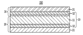
- FIG. 1 is a cross-sectional view schematically showing a polymer electrolyte membrane according to an embodiment of the present invention.
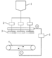
- FIG. 2 is a schematic view of a nozzle type electrospinning device.
- FIG. 3 is a schematic cross-sectional view of a membrane-electrode assembly according to an embodiment of the present invention.
- FIG. 4 is a schematic diagram showing the overall configuration of a fuel cell according to an embodiment of the present invention.
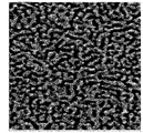
- 5 and 6 are AFM images of one side and the other side of the polymer electrolyte membrane prepared in Example 1-1 of the present invention.
- the alkyl group includes a primary alkyl group, a secondary alkyl group and a tertiary alkyl group, and is a straight chain or branched chain alkyl group having 1 to 10 carbon atoms, a halogenated alkyl group is a linear or branched
- the allyl group is an allyl group having 2 to 10 carbon atoms
- the aryl group is an aryl group having 6 to 30 carbon atoms
- the alkoxy group is an alkoxy group having 1 to 10 carbon atoms
- the alkylsulfonyl group is an alkyl group having 1 to 10 carbon atoms A sulfonyl group, an acyl group having 1 to 10 carbon atoms, and an aldehyde group having 1 to 10 carbon atoms.
- the amino group includes a primary amino group, a secondary amino group and a tertiary amino group, and a secondary amino group or a tertiary amino group is an amino group having 1 to 10 carbon atoms.
- substituted means that hydrogen is substituted with at least one substituent selected from the group consisting of a halogen atom, a hydroxyl group, a carboxyl group, a cyano group, a nitro group, an amino group, a cyano group, a methyl cyano group, an alkoxy group, a nitryl group, an aldehyde group, , A carboxyl group, an acetal group, a ketone group, an alkyl group, a perfluoroalkyl group, a cycloalkyl group, a heterocycloalkyl group, an allyl group, a benzyl group, an aryl group, a heteroaryl group, a derivative thereof, It means that one has been replaced.
- an asterisk (*) at both ends of the formula indicates that the compound is connected to another adjacent formula.
- an ion conductor including a repeating unit represented by one general formula not only means that it contains only a repeating unit represented by any one of the formulas contained in the above general formula, But may also include repeating units represented by various types of chemical formulas.
- the polymer electrolyte membrane according to an embodiment of the present invention includes a porous support including a plurality of pores, and an ion conductor filling the pores of the porous support.
- the fluorine-based support including a plurality of voids by the microstructure of the polymeric fibrils may include a plurality of voids due to a fine structure composed of nodes connected to each other by fibrils,
- the fluorine-based support may be an extended fluorine-based support.
- the fluorine-based support may comprise a fluorinated polymer, preferably a perfluorinated polymer, which is highly resistant to thermal and chemical degradation.
- the PTFE is commercially available and can be suitably used as the porous support and has a microstructure of a polymer fibril or a microstructure in which nodes are connected to each other by fibrils.
- (e-PTFE) sheet can also be suitably used as the porous support, and PTFE having the fine structure of the polymer fibril free from the nodule can be suitably used as the porous support.
- the e-PTFE sheet may have a porosity of at least 35%, and the diameter of the micropores may be about 0.01 ⁇ to 1 ⁇ .
- the thickness of the fluorine-based support may be from 2 ⁇ to 40 ⁇ , preferably from 5 ⁇ to 20 ⁇ . If the thickness of the fluorine-based support is less than 2 ⁇ , the mechanical strength may be significantly reduced. On the other hand, if the thickness exceeds 40 ⁇ , the resistance loss may increase and the weight and integration may be reduced.
- the nanoweb located on one side or both sides of the fluorine-based support may be a nanoweb integrated in the form of a nonwoven fabric in which the nanofibers include a plurality of voids.
- the nanofibers exhibit excellent chemical resistance and can be preferably used because they are hydrophobic and have no fear of morphological change due to moisture in a high humidity environment.
- the polymer include nylon, polyimide, polyaramid, polyetherimide, polyacrylonitrile, polyaniline, polyethylene oxide, polyethylene naphthalate, polybutylene terephthalate, styrene butadiene rubber, polystyrene, polyvinyl chloride, polyvinyl A hydrocarbon-based polymer such as an alcohol, polyvinylidene fluoride, polyvinyl butylene, polyurethane, polybenzoxazole, polybenzimidazole, polyamideimide, polyethylene terephthalate, polyphenylene sulfide, polyethylene, polypropylene; (Perfluoroacryl) vinyl ether co-polymer (PFA) or polytetrafluoroethylene (polyvinylidene difluoride), tetrafluoroethylene hex
- the nano-web may have a basis weight of 5 g / m 2 to 30 g / m 2 . If the basis weight of the nano-web is less than 5 g / m 2 , visible pores may be formed and it may be difficult to function as a porous support. If the basis weight of the nano-web exceeds 30 g / m 2 , Shaped.
- the thickness of the nano-web may be between 10 ⁇ m and 50 ⁇ m, and specifically between 15 ⁇ m and 43 ⁇ m. If the thickness of the nano-web is less than 10 ⁇ , the mechanical strength may be lowered. If the thickness of the nano-web is more than 50 ⁇ , the resistance loss may increase and the weight and integration may be decreased.
- the porosity of the heterogeneous complex porous support may be 45% or more, and may be 60% or more.
- the heterogeneous complex porous support preferably has a porosity of 90% or less. If the porosity of the heterogeneous composite porous support is more than 90%, the morphological stability may be deteriorated and the post-process may not proceed smoothly.
- the porosity can be calculated according to the ratio of the volume of air to the total volume of the heterogeneous complex porous support according to Equation (1).
- the total volume can be obtained by measuring the width, length, and thickness of a rectangular sample, and calculating the air volume by subtracting the volume of the polymer inversely calculated from the density after the measurement of the mass of the sample from the total volume.
- Porosity (%) (volume of air in heterogeneous complex porous support / total volume of heterogeneous complex porous support) X 100
- the heterogeneous complex porous support is a porous support comprising a mixture of the fluorine-based support and the nanomaterial of the nano-web.
- the heterogeneous composite material may have mechanical strength and resistance reduction effects.
- nano-web may be simply laminated on the fluorine-based support
- the nano-web is formed by electrospinning directly on one or both sides of the fluorine-based support, have.
- the polymer electrolyte membrane is a polymer electrolyte membrane in the form of a reinforced composite membrane in which an ion conductor is filled in the pores of the heterogeneous complex porous support.
- the polymer electrolyte membrane may include a first ion conductor layer disposed on one surface of the heterogeneous complex porous support and a second ion conductor layer disposed on another surface of the heterogeneous complex porous support.
- the first ion conductor layer and the second ion conductor layer may be formed in such a manner that the ion conductor remaining after filling the voids of the heterogeneous complex porous support forms a thin film on the surface of the heterogeneous complex porous support.
- FIG. 1 is a cross-sectional view schematically showing an example of the polymer electrolyte membrane 150.
- the polymer electrolyte membrane 150 includes a fluorine-based support 11 including a plurality of voids due to the microstructure of the polymeric fibrils, and a fluorine-based support 11 disposed on both sides of the fluorine- (10) comprising nanofibers (12) integrated into a nonwoven fabric comprising a plurality of voids.
- the first ion conductor layer 21 is located on one side of the heterogeneous complex porous support 10 and the second ion conductor layer 31 is located on the other side of the heterogeneous complex porous support 10.
- the first ion conductor layer 21 may comprise a first ion conductor 20 and the second ion conductor layer 31 may comprise a second ion conductor 30, 10 may include any one selected from the group consisting of the first ion conductor 20, the second ion conductor 30, and combinations thereof.
- the present invention is not limited thereto, and the first ion conductor layer 21 and the second ion conductor layer 31 may include the same ion conductor, 10 may also be filled with one ionic conductor.
- the first ion conductor 20 may include a combination of the first ion conductor 20 and the second ion conductor 30.
- the first ion conductor 20 may include a combination of the first ion conductor 20 and the second ion conductor 30, 1 ion conductor layer 21 is positioned and the second ion conductor 30 is filled with the heteropolyporous porous body 10 in which the second ion conductor layer 30 is located, The pores of the other surface of the support body 10 may be filled.
- the present invention is not limited to the above-described FIG. 1, and the pores of the heterogeneous complex porous support 10 may be filled with only the first ion conductor 20 or the second ion conductor 30.
- the first ion conductor and the second ion conductor may be different from each other.
- the first ion conductor and the second ion conductor may have equivalent weight (EW) or ion exchange capacity (IEC) Can be different from each other.
- the first ion conductor may have an equivalent weight (EW) of 300 g / eq to 950 g / eq, specifically 400 g / eq to 750 g / eq, EW) can be from 650 g / eq to 1500 g / eq, and more specifically from 800 g / eq to 1100 g / eq.
- EW equivalent weight
- the first ion conductor may have an ion exchange capacity (IEC) of 1.0 meq / g to 3.5 meq / g, specifically, 1.3 meq / g to 2.5 meq / g or less,
- the equivalent weight (EW) may be from 0.6 meq / g to 1.6 meq / g, and more specifically from 0.9 meq / g to 1.3 meq / g.
- the first ion conductor can exhibit a high ion conductivity efficiency, and the second ion conductor can secure the morphological stability and durability of the polymer electrolyte membrane itself while reducing the swelling property of the polymer electrolyte membrane.
- the first ion conductor on one surface of the porous support, it is possible to improve the ion conductivity and reduce the membrane resistance to improve the performance efficiency of the fuel cell, and on the other surface of the porous support, The shape stability of the polymer electrolyte membrane can be ensured and the durability performance of the polymer electrolyte membrane can be ensured.
- the thickness ratio of the first ion conductor layer may be 10% to 200%, particularly 50% to 100%, of the total thickness of the porous support, and the thickness ratio of the second ion conductor layer May be 10% to 200%, and more preferably 50% to 100%, of the total thickness of the porous support. If the thickness ratio of the first ion conductor layer and the second ion conductor layer is less than 10% by weight, ion conductivity may not be exhibited. If the thickness ratio exceeds 200%, the porous support may not serve as a support, Similar to the membrane, durability can be reduced.
- the thickness ratio of the ion conductor layer on one surface can be calculated by the following equation (2).
- the thickness ratio of the first ion conductor and the second ion conductor to the whole thickness of the polymer electrolyte membrane is 9: 1 to 1: 9, and may be from 9: 1 to 6: 4, and more specifically from 8: 2 to 6: 4.
- the thickness of the first ion conductor is thicker than the thickness of the second ion conductor in order to improve the ion conductivity of the polymer electrolyte membrane and to obtain the stability of the polymer electrolyte membrane.
- the thickness of the first ion conductor is the sum of the thickness of the first ion conductor impregnated into the internal void of the porous support and the thickness of the first ion conductor layer.
- the thickness of the second ion conductor is the sum of the thickness of the second ion conductor impregnated with the internal voids of the porous support and the thickness of the second ion conductor layer.
- the pores of the porous support are filled with the first ion conductor, and on one surface of the porous support, And the second ion conductor layer may be formed on the other surface of the porous support.
- first ion conductor and the second ion conductor may each be a cation conductor having a cation exchange group such as proton independently, or an anion conductor having an anion exchange group such as a hydroxide ion, a carbonate or a bicarbonate .
- the cation exchange group may be any one selected from the group consisting of a sulfonic acid group, a carboxyl group, a boronic acid group, a phosphoric acid group, an imide group, a sulfonimide group, a sulfonamide group, a sulfonic acid fluoride group, Or a carboxyl group.
- the cation conductor includes the cation-exchange group, and the fluorine-based polymer includes fluorine in the main chain; Polyimides, polyacetals, polyethylenes, polypropylenes, acrylic resins, polyesters, polysulfones, polyethers, polyetherimides, polyesters, polyethersulfones, polyetherimides, polyamides, polyamides, Hydrocarbon polymers such as carbonates, polystyrene, polyphenylene sulfide, polyether ether ketone, polyether ketone, polyaryl ether sulfone, polyphosphazene or polyphenylquinoxaline; Partially fluorinated polymers such as polystyrene-graft-ethylene tetrafluoroethylene copolymer, or polystyrene-graft-polytetrafluoroethylene copolymer; Sulfonimide, and the like.
- the polymer may include a cation exchanger selected from the group consisting of a sulfonic acid group, a carboxylic acid group, a phosphoric acid group, a phosphonic acid group and derivatives thereof in the side chain, Specific examples include poly (perfluorosulfonic acid), poly (perfluorocarboxylic acid), copolymers of tetrafluoroethylene and fluorovinyl ethers containing sulfonic acid groups, defluorinated sulfated polyether ketone, or mixtures thereof
- a fluorine-based polymer including; Sulfonated polyimide (S-PI), sulfonated polyarylethersulfone (S-PAES), sulfonated polyetheretherketone (SPEEK), sulfonated polybenzyl ether A sulfonated polybenzimidazole (SPBI), a sulfonated polybenzimidazole (SPBI), a sulf
- the anionic conductor is a polymer capable of transporting an anion such as a hydroxy ion, a carbonate or a bicarbonate, and an anion conductor is commercially available in the form of a hydroxide or a halide (generally chloride) water purification, metal separation or catalytic processes.
- an anion conductor is commercially available in the form of a hydroxide or a halide (generally chloride) water purification, metal separation or catalytic processes.
- a metal hydroxide-doped polymer may be used as the anion conductor.
- metal hydroxide doped poly ether sulfone
- polystyrene vinyl polymer
- poly (vinyl chloride) poly (vinylidene fluoride)
- Poly tetrafluoroethylene
- poly (benzimidazole) poly (ethylene glycol), and the like.
- the first ion conductor and the second ion conductor are a fluorinated polymer including a fluorinated side chain.
- the second ion conductor may have different lengths of the side chains.
- fluorinated means that at least 90 mole% of the total number of halogen and hydrogen atoms is replaced by fluorine atoms.
- the fluorinated polymer includes a polymer skeleton and cyclic side chains attached to the skeleton, and the side chains may have the ion exchange group.
- copolymers of a first fluorinated vinyl monomer and a second fluorinated vinyl monomer having a sulfonic acid group are examples of copolymers of a first fluorinated vinyl monomer and a second fluorinated vinyl monomer having a sulfonic acid group.
- the first fluorinated vinyl monomer may be at least one selected from the group consisting of tetrafluoroethylene (TFE), hexafluoropropylene, vinyl fluoride, vinylidine fluoride, trifluoroethylene, chlorotrifluoroethylene, perfluoro (alkyl vinyl ether)
- TFE tetrafluoroethylene
- vinyl fluoride vinylidine fluoride
- trifluoroethylene vinyl fluoride
- chlorotrifluoroethylene chlorotrifluoroethylene
- the second vinyl fluoride monomer having a sulfonic acid group may be a variety of fluorinated vinyl ethers having a sulfonic acid group.
- the side chain may be represented by the following formula (1).
- R f is independently any one selected from the group consisting of F, Cl, and fluorinated alkyl groups having 1 to 10 carbon atoms
- X is the ion exchange group, specifically, a sulfonic acid group
- a is a real number of 0 to 3, specifically 0 to 1.
- B is a real number of 1 to 5, specifically a real number of 2 to 4.
- the first ion conductor may have a side chain length a + b of 2 to 6, specifically 3 to 5, and the second ion conductor may have a side chain length a + b of 4 to 8 And specifically may be more than 5 and less than 7.
- the side chain length of the first ion conductor, a + b is less than 2
- the structural stability of the polymer electrolyte membrane may be deteriorated and the chemical durability may be decreased due to excessive moisture absorption, and ion conductivity and performance may be lowered .
- the side chain length a + b of the second ion conductor is less than 4, tensile strength and durability may be lowered, and if it exceeds 8, ion conductivity and performance may be deteriorated.
- the first ion conductor and the second ion conductor are polymers comprising a hydrophilic repeating unit and a hydrophobic repeating unit, and the first ion conductor and the second ion conductor are composed of the hydrophilic repeating unit and the hydrophobic repeating unit
- the molar ratios of the units may be different from each other.
- At least one monomer constituting the hydrophilic repeating unit is substituted by the ion exchange group and the monomer constituting the hydrophobic repeating unit is not substituted with the ion exchange group or is substituted with a smaller number of ion exchange groups than the hydrophilic repeating unit .
- the hydrophilic repeating unit may be composed of the monomer substituted with the ion exchange group and the monomer not substituted with the ion exchange group.
- first ion conductor and the second ion conductor are random copolymers in which the hydrophilic repeating unit and the hydrophobic repeating unit are randomly connected to each other or a hydrophobic block composed of the hydrophilic repeating units and a hydrophobic block composed of the hydrophobic repeating units And may be a block copolymer containing hydrophobic blocks composed of blocks.
- first ion conductor and the second ion conductor may each independently include a monomer having the hydrophilic repeating unit represented by the following formula (2).
- each of R 111 to R 114 , R 121 to R 124 , R 131 to R 134, and R 141 to R 144 independently represents a hydrogen atom, a halogen atom, an ion conducting group, An electron donating group, and an electron withdrawing group.
- the halogen atom may be any one selected from the group consisting of bromine, fluorine, and chlorine.
- the ion exchange group may be any cation exchange group selected from the group consisting of a sulfonic acid group, a carboxylic acid group and a phosphoric acid group as described above, and the cation exchange group may be preferably a sulfonic acid group.
- the ion exchange group may be an anion exchange group such as an amine group.
- the electron donating group may be any group selected from the group consisting of an alkyl group, an allyl group, an aryl group, an amino group, a hydroxyl group, and an alkoxy group as an organic group for releasing electrons, May be any one selected from the group consisting of an alkylsulfonyl group, an acyl group, a halogenated alkyl group, an aldehyde group, a nitro group, a nitroso group and a nitrile group.
- the alkyl group may be a methyl group, an ethyl group, a propyl group, a butyl group, an isobutyl group, an amyl group, a hexyl group, a cyclohexyl group or an octyl group
- the halogenated alkyl group may be a trifluoromethyl group, a pentafluoroethyl group, A propyl group, a perfluorobutyl group, a perfluoropentyl group, a perfluorohexyl group, etc.
- the allyl group may be a propenyl group or the like
- the aryl group may be a phenyl group, a pentafluorophenyl group or the like.
- the perfluoroalkyl group means a part of hydrogen atoms or an alkyl group in which all hydrogen atoms are substituted with fluorine.
- Z 11 is a divalent organic group which may be -O- or -S-, preferably -O-.
- the R 111 to R 114 , R 121 to R 124 , R 131 to R 134 , And at least one or more of R 141 to R 144 may be an ion exchange group.
- hydrophilic repeating unit may be represented by the following general formula (2-1) or (2-2).
- R 111 to R 114 , R 121 to R 124 , R 131 to R 134 , R 141 to R 144 , and Z 11 are the same as described above, do.
- R 211 to R 214 , R 221 to R 224, and R 231 to R 234 each independently represent a hydrogen atom; A halogen atom;
- An electron donating group selected from the group consisting of an alkyl group, an allyl group, an aryl group, an amino group, a hydroxyl group, and an alkoxy group;
- an electron withdrawing group selected from the group consisting of an alkylsulfonyl group, an acyl group, a halogenated alkyl group, an aldehyde group, a nitro group, a nitroso group and a nitrile group. Since the detailed descriptions of the substituents are the same as those described above, repetitive descriptions will be omitted.
- X 21 and X 22 may each independently be a single bond or a divalent organic group.
- the bivalent organic group is a bivalent organic group that attracts electrons or releases electrons, and specifically includes -CO-, -SO 2 -, -CONH-, -COO-, -CR 2 -, -C (CH 3 ) 2 -, -C (CF 3 ) 2 - and - (CH 2 ) n -.
- R ' is any one selected from the group consisting of a hydrogen atom, a halogen atom, an alkyl group, and a halogenated alkyl group
- n may be an integer of 1 to 10.
- Z 21 is a divalent organic group, which may be -O- or -S-, and preferably -O-.
- R 111 to R 114 , R 121 to R 124 , R 131 to R 134 , R 141 to R 144 , and Z 11 are the same as described above. do.
- R 311 to R 314 and R 321 to R 324 each independently represent a hydrogen atom; A halogen atom; An ion conducting group; An electron donating group selected from the group consisting of an alkyl group, an allyl group, an aryl group, an amino group, a hydroxyl group, and an alkoxy group; And an electron withdrawing group selected from the group consisting of an alkylsulfonyl group, an acyl group, a halogenated alkyl group, an aldehyde group, a nitro group, a nitroso group and a nitrile group. Since the detailed descriptions of the substituents are the same as those described above, repetitive descriptions will be omitted.
- X 31 represents a single bond, -CO-, -SO 2 -, -CONH-, -COO-, -CR 2 -, - (CH 2 ) n -, a cyclohexylidene group, A fluorenylidene group containing an ion-exchange group, -C (CH 3 ) 2 -, -C (CF 3 ) 2 -, -O- and -S- And R 'is any one selected from the group consisting of a hydrogen atom, a halogen atom, an alkyl group and a halogenated alkyl group, and n may be an integer of 1 to 10. Since the detailed descriptions of the substituents are the same as those described above, repetitive descriptions will be omitted.
- the cyclohexylidene group containing the ion-exchange group or the fluorenylidene group containing the ion-exchange group is a group in which the hydrogen of the cyclohexylidene group or the fluorenylidene group is a sulfonic acid group, a carboxylic acid group,
- the ion exchange group is selected from the group consisting of a combination of the ion exchange groups.
- Z 31 is a divalent organic group, which may be -O- or -S-, and preferably -O-.
- the n 31 may be an integer of 0 to 10, preferably 0 or an integer of 1.
- the first ion conductor and the second ion conductor may each independently include a monomer represented by the following general formula (3).
- R 211 to R 214 , R 221 to R 224 and R 231 to R 234 , X 21 , X 22 and Z 21 have the same meanings as described above, so repetitive description will be omitted.
- hydrophobic repeating unit may be represented by the following formula (3-1).
- R 211 to R 214 , R 221 to R 224, and R 231 to R 234 , X 21 , X 22 and Z 21 are the same as described above, .
- R 411 to R 414 and R 421 to R 424 each independently represent a hydrogen atom; A halogen atom; An electron donating group selected from the group consisting of an alkyl group, an allyl group, an aryl group, an amino group, a hydroxyl group, and an alkoxy group; And an electron withdrawing group selected from the group consisting of an alkylsulfonyl group, an acyl group, a halogenated alkyl group, an aldehyde group, a nitro group, a nitroso group and a nitrile group. Since the detailed descriptions of the substituents are the same as those described above, repetitive descriptions will be omitted.
- X 41 represents a single bond, -CO-, -SO 2 -, -CONH-, -COO-, -CR 2 -, - (CH 2 ) n -, a cyclohexylidene group, a fluorenylidene group, -C (CH 3 ) 2 -, -C (CF 3 ) 2 -, -O- and -S-, R 'represents a hydrogen atom, a halogen atom, an alkyl group and And a halogenated alkyl group, and n may be an integer of 1 to 10. Since the detailed descriptions of the substituents are the same as those described above, repetitive descriptions will be omitted.
- Z 41 is a divalent organic group, which may be -O- or -S-, and preferably -O-.
- the n 41 may be an integer of 0 to 10, preferably 0 or an integer of 1.
- first ion conductor and the second ion conductor may each independently include a monomer represented by the following formula (4).
- each of R 511 to R 513 independently represents a hydrogen atom; A halogen atom; An electron donating group selected from the group consisting of an alkyl group, an allyl group, an aryl group, an amino group, a hydroxyl group, and an alkoxy group; And an electron withdrawing group selected from the group consisting of an alkylsulfonyl group, an acyl group, a halogenated alkyl group, an aldehyde group, a nitro group, a nitroso group and a nitrile group. Since the detailed descriptions of the substituents are the same as those described above, repetitive descriptions will be omitted.
- Z 51 is a divalent organic group, which may be -O- or -S-, and preferably -O-.
- hydrophobic repeating unit may be represented by the following formula (4-1).
- R 511 to R 513 , and Z 51 are the same as those described above, and therefore, a repetitive description thereof will be omitted.
- R 611 to R 614 and R 621 to R 624 each independently represent a hydrogen atom; A halogen atom; An electron donating group selected from the group consisting of an alkyl group, an allyl group, an aryl group, an amino group, a hydroxyl group, and an alkoxy group; And an electron withdrawing group selected from the group consisting of an alkylsulfonyl group, an acyl group, a halogenated alkyl group, an aldehyde group, a nitro group, a nitroso group and a nitrile group. Since the detailed descriptions of the substituents are the same as those described above, repetitive descriptions will be omitted.
- X 61 represents a single bond, -CO-, -SO 2 -, -CONH-, -COO-, -CR 2 -, - (CH 2 ) n -, a cyclohexylidene group, a fluorenylidene group, -C (CH 3 ) 2 -, -C (CF 3 ) 2 -, -O- and -S-, R 'represents a hydrogen atom, a halogen atom, an alkyl group and And a halogenated alkyl group, and n may be an integer of 1 to 10. Since the detailed descriptions of the substituents are the same as those described above, repetitive descriptions will be omitted.
- Each Z 61 independently represents a divalent organic group, -O- or -S-, and preferably -O-.
- N 61 may be an integer of 0 to 10, preferably 0 or an integer of 1.
- the first ion conductor and the second ion conductor may independently have the hydrophobic repeating unit represented by the following formula (5-1).
- R 211 to R 214, R 221 to R 224, R 231 to R 234, R 311 to R 314, R 321 to R 324, R 411 to R 414, R 421 to R 424, R 511 to R 513, R 611 To R 614 , and R 621 to R 624 are preferably substantially free of ion exchange groups.
- R 211 to R 214, R 221 to R 224, R 231 to R 234, R 311 to R 314, R 321 to R 324, R 411 to R 414, R 421 to R 424, R 511 to R 513, R 611 To R 614 , and R 621 to R 624 are preferably substantially free of ion exchange groups.
- the first ion conductor and the second ion conductor may each independently include a monomer having the hydrophilic repeating unit or the hydrophobic repeating unit represented by the following formula (6).
- the first ion conductor or the second ion conductor further comprises a monomer represented by the general formula (6)
- the first ion conductor or the second ion conductor includes a nitrogen-containing aromatic ring group in the main chain, And the interaction of the acid-base is improved. Accordingly, the first ion conductor or the second ion conductor does not cause addition reaction to the aromatic ring of the polymer electrolyte membrane or breakage of the aromatic ring due to attack of radicals formed on the cathode side during the operation of the fuel cell, By maximizing the function of the group, it is possible to improve the fuel cell operating performance in a low humidity state.
- Z is -O- or -S-, preferably -O-.
- Y is a divalent nitrogen-containing aromatic ring group.
- the nitrogen-containing aromatic ring group means that at least one nitrogen atom is contained as a hetero atom in the aromatic ring.
- other hetero atoms may include an oxygen atom, a sulfur atom, and the like.
- the divalent nitrogen-containing aromatic ring group may be a pyrrole, thiazole, isothiazole, oxazole, isoxazole, imidazole, imidazoline, imidazolidine, pyrazole, triazine, pyridine, pyrimidine, Pyridazine, pyrazine, indole, quinoline, isoquinoline, tetrazole, tetrazine, triazole, carbazole, quinoxaline, quinazoline, indolizine, isoindole, indazole, phthalazine, naphthyridine, May be a divalent group of any nitrogen-containing aromatic ring compound selected from the group consisting of imidazole, imidazole, pyrrolidine, pyrroline, pyrazoline, pyrazolidine, piperidine, piperazine and indoline.
- the first ion conductor and the second ion conductor may have a weight average molecular weight of 10,000 g / mol to 1,000,000 g / mol, and preferably have a weight average molecular weight of 100,000 g / mol to 500,000 g / mol. If the weight average molecular weight of the first ion conductor and the second ion conductor is less than 100,000 g / mol, uniform film formation may be difficult and durability may be deteriorated. When the weight average molecular weight of the first ion conductor and the second ion conductor exceeds 500,000 g / mol, the solubility can be reduced.
- the heterogeneous complex porous support is a polymer- Which is advantageous in terms of film stability.
- the ion conductor is easily desorbed or discharged from the heterogeneous complex porous support, You may lose your sex.
- the first ion conductor and the second ion conductor may be prepared by preparing the hydrophilic repeating unit and the hydrophobic repeating unit, respectively, and then subjecting the hydrophilic repeating unit and the hydrophobic repeating unit to a nucleophilic substitution reaction have.
- the hydrophilic repeating unit and the hydrophobic repeating unit may be produced by a nucleophilic substitution reaction.
- the hydrophilic repeating unit is the repeating unit represented by the above formula (2-2)
- It can be prepared by an aromatic nucleophilic substitution reaction of an active dihalide monomer having two components constituting the repeating unit represented by the above formula (3-1) and a dihydroxy monomer.
- hydrophilic repeating unit is a repeating unit represented by Formula 2-2, sulfonated dichlorodiphenyl sulfone (SDCDPS), sulfonated difluorodiphenyl sulfone (SDCDPS), sulfonated dichlorodiphenyl ketone (SDCDPK), DCDPS dichlorodiphenyl sulfone), DFDPS (difluorodiphenyl sulfone or Bis- (4-fluorophenyl) -sulfone) or DCDPK (dichlorodiphenyl ketone), and the active dihydroxy monomer such as SHPF (sulfonated 9,9'- sulfonated 4,4 '- (9-Fluorenylidene biphenol) or HPF (9,9'-bis (4-hydroxyphenyl) fluorine or 4,4' - (9-Fluorenylidene biphenol) .
- SHPF sulfonated 9,
- 1,3-bis (4-fluorobenzoyl) benzene may be used as the active dihalide monomer.
- DHDPS dihydroxydiphenyl sulfone
- DHDPK dihydroxydiphenyl ketone
- BP 4,4'-biphenol
- hydrophobic repeating unit is a repeating unit represented by the above-mentioned formula (4-1), 2,6-difluorobenzonitrile or the like is used as the active dihalide monomer, and the active dihydroxy monomer Dihydroxydiphenyl sulfone (DHDPS), dihydroxydiphenyl ketone or dihydroxybenzophenone (DHDPK), or BP (4,4'-biphenol).
- DHDPS Dihydroxydiphenyl sulfone
- DHDPK dihydroxydiphenyl ketone
- BP 4,4'-biphenol
- both ends of the hydrophilic repeating unit are hydroxyl groups and both ends of the hydrophobic repeating unit are controlled to a halide group
- Unit is a hydroxyl group and both ends of the hydrophilic repeating unit are controlled by a halide group
- the hydrophilic repeating unit and the hydrophobic repeating unit can be subjected to a nucleophilic substitution reaction.
- the nucleophilic substitution reaction may be preferably carried out in the presence of an alkaline compound.
- the alkaline compound may be specifically exemplified by sodium hydroxide, potassium hydroxide, sodium carbonate, potassium carbonate, sodium hydrogencarbonate, and the like, and either one of them or a mixture of two or more of them may be used.
- the nucleophilic substitution reaction may be carried out in a solvent.
- the solvent include N, N-dimethylacetamide, N, N-dimethylformamide, N-methyl methylpyrrolidone, dimethyl sulfoxide, sulfolane, or 1,3-dimethyl-2-imidazolidinone, in the presence of an aprotic polar solvent, These may be used alone or in combination of two or more.
- a solvent such as benzene, toluene, xylene, hexane, cyclohexane, octane, chloro benzene, dioxane dioxane, tetrahydrofuran, anisole, phenetole and the like can be coexistent.
- the method further comprises introducing an ion exchange group into the first ion conductor and the second ion conductor.
- the ion exchange group is a sulfonic acid group, which is a cation exchange group
- the ion exchange group may be introduced into the ion conductor by the following two methods.
- SDCDPS dichlorodiphenyl sulfone
- SDCDPS sulfonated difluorodiphenyl sulfone
- SDCDPK sulfonated dichlorodiphenyl ketone
- 9,9'-bis 4-hydroxyphenyl) fluorine or sulfonated 4,4 '- (9-Fluorenylidene biphenol sulfonated dichlorodiphenyl sulfone
- SDCDPK sulfonated dichlorodiphenyl ketone
- the sulfonic acid ester group may be replaced with a monomer having an ester group to prepare the polymer having the sulfonic acid ester group, and then the sulfonic acid ester group may be de-esterified, A method of converting a group into a sulfonic acid group may be used.
- an ion exchange group may be introduced into the hydrophilic repeating unit by preparing a polymer using a monomer not containing the ion exchange group and sulfonating the polymer using a sulfonating agent.
- sulfuric acid can be used as the sulfonating agent.
- another example is a method in which the polymer is reacted in the presence of an excess amount of chlorosulfonic acid (1 to 10 times, preferably 4 to 7 times, based on the total weight of the polymer) The reaction can proceed in a chlorinated solvent such as dichloromethane, chloroform, and 1,2-dichloroethane to produce an ion conductor having hydrogen ion conductivity.
- the ionic conductor may have a degree of sulfonation of 1 mol% to 100 mol%, preferably 50 mol% to 100 mol% . That is, the ion conductor may be a 100 mol% sulfonation site at a site that can be sulfonated, and even if the ion conductor is 100 mol% sulfonated, the dimensional stability and durability of the ion conductor may be deteriorated due to the structure of the block copolymer There is no effect. In addition, when the ion conductor has a degree of soda saturation as described above, excellent ion conductivity can be exhibited without deteriorating dimensional stability.
- the structure control can be easily controlled and the characteristics as an ion conductor can be easily controlled.
- the structure-controlled ion conductor can provide an ion conductor having improved ion conductivity and durability within the entire humidifying range due to the fine phase separation of the hydrophilic repeating unit and the hydrophobic repeating unit.
- the molar ratio of the hydrophilic repeating unit to the hydrophobic repeating unit means the number of moles of the hydrophobic repeating unit contained in the first ion conductor or the second ion conductor per 1 mole of the hydrophilic repeating unit
- the second ionic conductor may independently have a molar ratio of the hydrophilic repeating unit to the hydrophobic repeating unit of 1: 0.5 to 1:10, and may be specifically 1: 1 to 1: 5, and more specifically, 1: greater than 1.2 to 1: 5. If the molar ratio of the hydrophobic repeating units is less than 0.5, the water content increases and the dimensional stability and durability may deteriorate. If the molar ratio exceeds 10, the ion conductivity may not be exhibited.
- the molar ratios of the hydrophilic repeating unit and the hydrophobic repeating unit may be different from each other, and even when they are composed of the same repeating units, The molar ratios of the repeating unit and the hydrophobic repeating unit may be different from each other. That is, by varying the molar ratios of the hydrophilic repeating unit and the hydrophobic repeating unit from each other, the characteristics of the expression performance can be controlled by the first ion conductor and the second ion conductor.
- the first ion conductor may have a higher molar ratio of the hydrophilic repeating unit to the hydrophobic repeating unit than the molar ratio of the hydrophilic repeating unit to the hydrophobic repeating unit of the second ion conductor.
- the molar ratio of the hydrophilic repeating unit to the hydrophobic repeating unit may be 1: 2 to 1: 5, specifically 1: 2 to 1: 3, and the second ion
- the conductor may have a molar ratio of the hydrophilic repeating unit to the hydrophobic repeating unit of 1: 3 to 1: 6, and specifically 1: 3 to 1: 4, wherein the first ion conductor and the second ion Even if the molar ratio of the hydrophilic repeating unit to the hydrophobic repeating unit of the conductor is overlapped, the first ion conductor may be higher than the molar ratio of the hydrophilic repeating unit to the hydrophobic repeating unit have.
- the ion conductivity can be improved and the membrane resistance can be reduced.
- the morphology stability of the polymer electrolyte membrane can be ensured by introducing the second ion conductor having a high molar ratio of the unit.
- any one selected from the group consisting of the heterogeneous complex porous support, the first ion conductor layer, and the second ion conductor layer may further include an antioxidant.
- hydroxyl radicals ( ⁇ OH - ) can be generated from hydrogen peroxide or the generated hydrogen peroxide at the cathode electrode .
- the hydrogen peroxide or the hydroxyl radical may be generated in the anode electrode as oxygen molecules permeate the polymer electrolyte membrane. The generated hydrogen peroxide or hydroxyl radical causes degradation of the polymer electrolyte membrane or a polymer containing a sulfonic acid group contained in the catalyst layer.
- the antioxidant capable of decomposing the peroxide or the radical By including the antioxidant capable of decomposing the peroxide or the radical, the generation of radicals from the peroxide can be suppressed or the generated radical can be decomposed to prevent deterioration of the polymer electrolyte membrane or the catalyst layer, The chemical durability of the film can be improved.
- the antioxidant capable of decomposing the peroxide or radical is not particularly limited as long as it is capable of rapidly decomposing peroxides (in particular, hydrogen peroxide) or radicals (particularly hydroxyl radicals) generated during operation of the polymer electrolyte fuel cell, All are available.
- the antioxidant capable of decomposing the peroxide or the radical may be a transition metal capable of decomposing the peroxide or radical, a noble metal capable of decomposing the peroxide or radical, an ionic form thereof, a salt form thereof , Or an oxide thereof.
- the transition metal capable of decomposing the peroxide or the radical may be at least one selected from the group consisting of Ce, Ni, W, Co, Cr, Zr, Y, And may be any one selected from the group consisting of Mn, Fe, Ti, V, Mo, La and Ne.
- the noble metal capable of decomposing the peroxide or radical may be any one selected from the group consisting of Au, Pt, Ru, Pd and Rh.
- the transition metal capable of decomposing the peroxide or radical or the ion of the noble metal may be at least one selected from the group consisting of cerium ion, nickel ion, tungsten ion, cobalt ion, chromium ion, zirconium ion, yttrium ion, manganese ion, iron ion, ion, molybdenum ion, a lanthanum ion, neodymium ion, silver ion, a platinum ion, a ruthenium ion, a palladium ion, and may be any one selected from the group consisting of rhodium ion, for example the cerium in detail example cerium trivalent ions (Ce 3 + ) Or a cerium tetravalent ion (Ce 4+ ).
- the transition metal capable of decomposing the peroxide or radical or the oxide of the noble metal may be at least one selected from cerium oxide, nickel oxide, tungsten oxide, cobalt oxide, chromium oxide, zirconium oxide, yttrium oxide, manganese oxide, Vanadium, molybdenum oxide, lanthanum oxide, and neodymium oxide.
- the transition metal capable of decomposing the peroxide or radical or the salt of the noble metal may be a carbonate, a nitrate, Ammonium salts and acetylacetonate salts.
- cerium include cerium carbonate, cerium acetate, cerium chloride, cerium acetate, cerium sulfate, cerium ammonium acetate, cerium ammonium sulfate, and the like.
- cerium acetylacetonate as the organic metal complex salt.
- the antioxidant capable of decomposing the peroxide or the radical is dispersed in the polymer electrolyte membrane or the catalyst electrode in order to prevent deterioration due to radicals of the polymer electrolyte membrane, the peroxide or the radical is decomposed during operation of the fuel cell There may be a problem that an antioxidant that can be dissolved is eluted.
- it may include an organic second antioxidant capable of fixing the antioxidant.
- the organic second antioxidant may be a compound containing a resonance structure based on a double bond of a carboxylic acid, a hydroxyl group and carbon.
- the organic second antioxidant having such a structure has a molecular size effect that can not utilize a passage eluted as it has a larger molecular size than the ion clusters and channels in the polymer electrolyte membrane, The hydroxyl group and the polymer in the polymer electrolyte membrane can be prevented from being eluted through hydrogen bonding.
- organic second antioxidant examples include syringic acid, vanillic acid, protocatechuic acid, coumaric acid, caffeic acid, ferulic acid, acid, chlorogenic acid, cynarine, galic acid, and mixtures thereof.
- the second antioxidant may be included in an amount of 0 to 200 parts by weight based on 100 parts by weight of the first antioxidant, 30 parts by weight to 100 parts by weight.
- the antioxidant is similar to the case of using only the first antioxidant. Therefore, when the content of the second antioxidant is more than 200 parts by weight, The uniformity of the inside of the polymer electrolyte membrane may be lowered.
- a method of manufacturing a polymer electrolyte membrane comprising: preparing a fluorine-based support including a plurality of voids by a microstructure of a polymeric fibril; electrospinning the nanofibers on one or both surfaces of the fluorine- Forming a nanocomposite in the form of a nonwoven fabric including a plurality of voids to prepare a heterogeneous composite porous support, and filling the pores of the heterogeneous composite porous support with an ion conductor.
- the PTFE powder produced by the dispersion polymerization is extruded into a rod-shaped paste in the presence of a lubricant such as solvent naphtha or white oil, and the rod-shaped paste extrusion
- a lubricant such as solvent naphtha or white oil
- the water (cake) is rolled to prepare a PTFE-free sheet.
- the unfired sheet is stretched at an arbitrary ratio in the longitudinal direction (MD direction) and / or the width direction (TD direction).
- the elongated PTFE sheet can be produced by removing the charged liquid lubricant during or after the elongation by heating or extraction.
- the amorphous content of the PTFE may be increased by heat-treating the elongated PTFE (e-PTFE) at a temperature exceeding the melting point of the PTFE (about 342 ° C).
- the nanofibers are electrospun on one side or both sides of the fluorine-based support to form a nano-web in which the nanofibers are integrated in the form of a nonwoven fabric including a plurality of voids to prepare a heterogeneous composite porous support.
- the step of forming the nano-web includes the steps of preparing an electrospinning solution, and electrospinning the prepared electrospinning solution on one surface or both surfaces of the heterogeneous composite porous substrate.
- the step of preparing the electrospinning solution is to prepare a solution containing a polymer for forming nanofibers through electrospinning.
- the electrospinning solution may be a solution of a polymer used in the above- N-dimethylacetamide, N, Ndimethyl formamide, dimethylsulphoxide, N-methyl-2-pyrolidone, triethylphosphate, methyl
- the prepared electrospinning solution is electrospun to produce a nano-web in which nanofibers are integrated into a nonwoven fabric including a plurality of pores.
- the electrospinning may be performed using the electrospinning apparatus shown in FIG. 2 is a schematic view of a nozzle type electrospinning device. 2, the electrospinning is performed by using a metering pump 2 in a solution tank 1 in which the electrospinning solution is stored, a plurality of nozzles 3 to which high voltage is applied by the high voltage generator 6, The electrospinning solution is fed to the electrospinning solution by the difference in electric energy between the nozzle 3 or the tip of the electrospinning unit and the accumulation unit 4, that is, the voltage difference. The formed jet is whipped and stretched by the electric field to become thinner and the solvent is vaporized so that solid fibers are accumulated in the integrated portion 4. [
- the nanofiber composing the nanofiber is polyimide
- the nanofiber may be prepared by electrospinning a polyamic acid (PAA) to form a nanofiber precursor comprising the PAA nanofibers, followed by a subsequent heat treatment or chemical imaging Can be prepared through a hydrogenation reaction.
- PAA polyamic acid
- the pores of the heterogeneous complex porous support are filled with an ion conductor.
- the step of filling the voids of the heterogeneous complex porous support with the ion conductor may be carried out by impregnating or impregnating the heterogeneous complex porous support in a solution containing the ion conductor.
- the step of filling the pores of the heterogeneous complex porous support with an ion conductor includes the steps of: forming a first ion conductor layer including a first ion conductor on one surface of the heterogeneous complex porous support; 2 < / RTI > ionic conductor to form a second ion conductor layer.
- the first ion conductor is filled in the pores of one surface of the heterogeneous complex porous support, and the first ion conductor remaining on the surface of the heterogeneous complex porous support is filled with a first ion conductor
- the second ion conductor is filled in the pores of the other surface of the heterogeneously complex porous support, and the second ion conductor remaining on the other surface of the heterogeneous complex porous support is filled with the second ion conductor on the surface of the other surface of the heterogeneously complex porous support.
- the pores of the heterogeneous complex porous support may be filled only with the first ion conductor, and after forming the first ion conductor layer, It is also possible to form only the second ion conductor layer on the other surface of the substrate.
- the step of filling the voids of the heterogeneous complex porous support with the first ion conductor and the second ion conductor generally comprises the step of supporting or impregnating the heterogeneous complex porous support with a solution containing the first ion conductor or the second ion conductor .
- the step of filling the voids of the heterogeneous composite porous support with the first ion conductor and the second ion conductor may be performed by a combination of bar coating, comma coating, slot die, screen printing, spray coating, doctor blade, laminating and combinations thereof Or by a method selected from the group.
- the existing processes may be used as they are, except that the first ion conductor and the second ion conductor are filled on one surface and the other surface of the heterogeneous complex porous substrate, respectively.
- the first ion conductor and the second ion conductor may be filled into the heterogeneous complex porous support in the form of a solution or dispersion containing the same.
- the solution or dispersion containing the first ion conductor or the second ion conductor may be prepared by using a commercially available ion conductor solution or dispersion and dispersing the first ion conductor or the second ion conductor in a solvent It is possible.
- the method of dispersing the first ion conductor or the second ion conductor in a solvent can be carried out by a conventionally known method, and thus a detailed description thereof will be omitted.
- the antioxidant may further be added to the solution or dispersion containing the first ion conductor or the second ion conductor.
- the antioxidant may be contained only in the first ion conductor layer or only a part of the heterogeneous complex porous support.
- the content of the antioxidant added to the solution or dispersion containing the first ion conductor or the second ion conductor can be controlled, The amount of the antioxidant to 100 parts by weight of the ion conductor can be controlled.
- a solvent selected from the group consisting of water, a hydrophilic solvent, an organic solvent and a mixture of at least one of them may be used.
- the hydrophilic solvent may be any one selected from the group consisting of alcohols containing linear or branched saturated or unsaturated hydrocarbons having 1 to 12 carbon atoms as the main chain, isopropyl alcohol, ketone, aldehyde, carbonate, carboxylate, carboxylic acid, ether and amide , Which may contain an alicyclic or aromatic cyclic compound as at least a part of the backbone.
- the organic solvent may be selected from N-methylpyrrolidone, dimethylsulfoxide, tetrahydrofuran, and mixtures thereof.
- filling the pores of the heterogeneous complex porous support with the first ion conductor or the second ion conductor may be affected by various factors such as the temperature and the time.
- the thickness of the heterogeneous complex porous support, the concentration of the solution or dispersion containing the first ion conductor or the second ion conductor, the type of the solvent, and the like may be affected.
- the process may be performed at a temperature of 100 ° C or lower at any point of the solvent, and more usually at a temperature of room temperature (20 ° C) to 70 ° C or lower for about 5 to 30 minutes.
- the temperature can not be higher than the melting point of the heterogeneous complex porous support.
- the method for producing a polymer electrolyte membrane may further include the steps of: preparing a plurality of the heterogeneous complex porous supports comprising the first ion conductor and the second ion conductor; and laminating the plurality of heterogeneously complex porous supports .
- the laminating method can be applied when the plurality of heterogeneous composite porous supports are laminated, and the polymer electrolyte membrane having high efficiency can be manufactured by easily adjusting the thickness ratio required in the fuel cell through the lamination of the heterogeneous composite porous supports.
- a membrane-electrode assembly including the polymer electrolyte membrane and a fuel cell.
- the membrane-electrode assembly includes an anode electrode and a cathode electrode positioned opposite to each other, and the polymer electrolyte membrane positioned between the anode electrode and the cathode electrode.
- the membrane-electrode assembly 100 includes the polymer electrolyte membrane 150 and the fuel cell electrodes 120 and 120 'disposed on both sides of the polymer electrolyte membrane 150 do.
- an oxidation reaction is performed on one surface of the polymer electrolyte membrane 150 to generate hydrogen ions and electrons from the fuel passed through the electrode substrate 140 to the catalyst layer 130.
- the electrode 120 causing the polymer electrolyte membrane 150 is referred to as an anode electrode and hydrogen ions supplied to the other surface of the polymer electrolyte membrane 150 through the polymer electrolyte membrane 150 pass through the electrode substrate 140 '
- the electrode 120 'that generates a reducing reaction to generate water from the oxidant transferred to the cathode 130' is referred to as a cathode electrode.
- the catalyst layers 130 and 130 'of the anode and cathode electrodes 120 and 120' include a catalyst. Any of the catalysts which can participate in the reaction of the battery and can be used as a catalyst of a fuel cell can be used. Specifically, a platinum-based metal may be preferably used.
- the platinum group metal may be at least one selected from the group consisting of platinum (Pt), palladium (Pd), ruthenium (Ru), iridium (Ir), osmium (Os), platinum-M alloy (M is palladium (Pd), ruthenium (Ir), Os, Ga, Ti, V, Cr, Mn, Fe, Co, Ni, (Rh), and at least one selected from the group consisting of Cu, Cu, Ag, Au, Zn, Sn, Mo, W, Or more), a non-platinum alloy, and combinations thereof, and more preferably, a combination of two or more metals selected from the platinum-based catalyst metal group may be used, but is limited thereto And can be used without limitation as long as it is a platinum-based catalyst metal usable in the technical field.
- the platinum alloy may be at least one selected from the group consisting of Pt-Pd, Pt-Sn, Pt-Mo, Pt-Cr, Pt-W, Pt-Ru, Pt- Pt-Co-Fe, Pt-Co-Ni, Pt-Co-Fe, Pt, Pt-Cr, Pt-Ni, Ir, Pt-Fe-S, Pt-Fe-P, Pt-Au- Ir, and combinations thereof, or a mixture of two or more thereof.
- the non-platinum alloy may be at least one selected from the group consisting of Ir-Fe, Ir-Ru, Ir-Os, Co-Fe, Co-Ru, Co-Os, Rh-Fe, Rh- -Ru-Os, Rh-Ru-Fe, Rh-Ru-Os, and combinations thereof, or a mixture of two or more thereof.
- Such a catalyst may be used as the catalyst itself (black) or may be supported on a carrier.
- the carrier may be selected from a carbon-based carrier, porous inorganic oxides such as zirconia, alumina, titania, silica, and ceria, zeolite, and the like.
- the carbon carrier may be selected from the group consisting of graphite, super P, carbon fiber, carbon sheet, carbon black, Ketjen black, Denka black, Carbon black, carbon black, acetylene black, carbon nano tube (CNT), carbon sphere, carbon ribbon, fullerene, activated carbon, carbon nanofiber, Carbon nanoclay, carbon nanorings, ordered nano- / meso-porous carbon, carbon aerogels, mesoporous carbon, graphene, stabilized carbon, activated carbon, and May be selected from a combination of one or more of them, but the present invention is not limited thereto, and carriers usable in the art can be used without limitation.
- the catalyst particles may be located on the surface of the carrier or may penetrate into the interior of the carrier while filling the internal pores of the carrier.
- a noble metal supported on the support When a noble metal supported on the support is used as a catalyst, a commercially available commercially available noble metal may be used, or a noble metal supported on a support may be used. Since the process of supporting the noble metal on the carrier is well known in the art, a detailed description thereof is omitted herein, and it is easily understandable to those skilled in the art.
- the catalyst particles may be contained in an amount of 20% by weight to 80% by weight based on the total weight of the catalyst layers 130 and 130 '. If the amount is less than 20% by weight, , The agglomeration of the catalyst particles may cause the active area to be reduced and the catalytic activity to be lowered inversely.
- the catalyst layers 130 and 130 ' may include a binder for enhancing adhesion of the catalyst layers 130 and 130' and for transferring hydrogen ions.
- a binder for enhancing adhesion of the catalyst layers 130 and 130' and for transferring hydrogen ions.
- the binder it is preferable to use an ion conductor having ion conductivity. Since the description of the ion conductor is the same as that described above, repetitive description will be omitted.
- the ionic conductor may be used singly or as a mixture, and may also be used together with a nonconductive compound for the purpose of further improving adhesion to the polymer electrolyte membrane 150. It is preferable to adjust the amount thereof to suit the purpose of use.
- nonconductive compound examples include polytetrafluoroethylene (PTFE), tetrafluoroethylene-hexafluoropropylene copolymer (FEP), tetrafluoroethylene-perfluoroalkyl vinyl ether copolymer (PFA), ethylene / tetrafluoro (PVdF-HFP), dodecyltrimethoxysilane (DMSO), ethylene tetrafluoroethylene (ETFE), ethylene chlorotrifluoroethylene copolymer (ECTFE), polyvinylidene fluoride, polyvinylidene fluoride-hexafluoropropylene copolymer At least one selected from the group consisting of benzene sulfonic acid and sorbitol may be used.
- PTFE polytetrafluoroethylene
- FEP tetrafluoroethylene-hexafluoropropylene copolymer
- PFA tetrafluoroethylene-perflu
- the binder may be included in an amount of 20% by weight to 80% by weight based on the total weight of the catalyst layers 130 and 130 '. If the content of the binder is less than 20% by weight, generated ions may not be transferred well. If the content of the binder is more than 80% by weight, it is difficult to supply hydrogen or oxygen (air) Can be reduced.
- a porous conductive substrate may be used as the electrode substrate 140 or 140 'so that hydrogen or oxygen can be supplied smoothly.
- a metal film is formed on the surface of a cloth formed of a porous film or polymer fiber composed of carbon paper, carbon cloth, carbon felt or metal cloth ) May be used, but the present invention is not limited thereto.
- the electrode substrate 140 or 140 ' is made of a fluorine-based resin that is water repellent to prevent the reactant diffusion efficiency from being lowered due to water generated when the fuel cell is driven.
- fluorine-based resin examples include polytetrafluoroethylene, polyvinylidene fluoride, polyhexafluoropropylene, polyperfluoroalkyl vinyl ether, polyperfluorosulfonyl fluoride alkoxyvinyl ether, fluorinated ethylene propylene ( Fluorinated ethylene propylene), polychlorotrifluoroethylene, or copolymers thereof.
- the microporous layer may further include a microporous layer for enhancing the reactant diffusion effect in the electrode substrate 140 or 140 '.
- the microporous layer is generally composed of a conductive powder having a small particle diameter such as carbon powder, carbon black, acetylene black, activated carbon, carbon fiber, fullerene, carbon nanotube, carbon nanowire, carbon nano -horn) or a carbon nano ring.
- the microporous layer is prepared by coating a composition comprising conductive powder, a binder resin and a solvent on the electrode substrate 140, 140 '.
- the binder resin include polytetrafluoroethylene, polyvinylidene fluoride, polyhexafluoropropylene, polyperfluoroalkyl vinyl ether, polyperfluorosulfonyl fluoride, alkoxyvinyl ether, polyvinyl alcohol, cellulose acetate Or a copolymer thereof, and the like can be preferably used.
- the solvent examples include alcohols such as ethanol, isopropyl alcohol, n-propyl alcohol and butyl alcohol, water, dimethylacetamide, dimethylsulfoxide, N-methylpyrrolidone and tetrahydrofuran.
- the coating process may be performed by a screen printing method, a spray coating method or a coating method using a doctor blade, depending on the viscosity of the composition, but is not limited thereto.
- the membrane-electrode assembly 100 can be manufactured according to a conventional method for manufacturing a membrane-electrode assembly for a fuel cell, except that the polymer electrolyte membrane 150 according to the present invention is used as the polymer electrolyte membrane 150 have.
- the fuel cell according to another embodiment of the present invention may include the membrane-electrode assembly 100 described above.
- FIG. 4 is a schematic diagram showing the overall configuration of the fuel cell.
- the fuel cell 200 includes a fuel supply unit 210 for supplying mixed fuel in which fuel and water are mixed, a reforming unit 210 for reforming the mixed fuel to generate a reformed gas containing hydrogen gas A stack 230 for generating an electric energy by generating an electrochemical reaction with a reforming gas containing hydrogen gas supplied from the reforming unit 220 with an oxidizing agent and a stack 230 for oxidizing the oxidizing agent to the reforming unit 220 and the stack 220.
- an oxidizing agent supply unit 240 supplying the oxidizing agent to the anode 230.
- the stack 230 includes a plurality of unit cells for generating an electric energy by inducing an oxidation / reduction reaction of a reforming gas containing hydrogen gas supplied from the reforming unit 220 and an oxidizing agent supplied from the oxidizing agent supplying unit 240 Respectively.
- Each of the unit cells refers to a cell that generates electricity.
- the unit cell includes a reformed gas containing hydrogen gas and the membrane-electrode assembly for oxidizing / reducing oxygen in the oxidant, a reforming gas containing hydrogen gas, (Or a bipolar plate, hereinafter referred to as a separator plate) for supplying the membrane-electrode assembly to the membrane-electrode assembly.
- the separator is disposed on both sides of the membrane-electrode assembly with the center thereof as the center. At this time, the separator located on the outermost side of the stack may be referred to as an end plate.
- the end plate of the separation plate is provided with a pipe-shaped first supply pipe (231) for injecting a reformed gas containing hydrogen gas supplied from the reforming unit (220), and a pipe-shaped second supply pipe A first discharge pipe 233 for discharging the reformed gas containing hydrogen gas remaining unreacted in the plurality of unit cells to the outside, And a second exhaust pipe 234 for discharging the remaining oxidizing agent to the outside.
- a pipe-shaped first supply pipe (231) for injecting a reformed gas containing hydrogen gas supplied from the reforming unit (220)
- a pipe-shaped second supply pipe A first discharge pipe 233 for discharging the reformed gas containing hydrogen gas remaining unreacted in the plurality of unit cells to the outside
- a second exhaust pipe 234 for discharging the remaining oxidizing agent to the outside.
- the separator, the fuel supply unit, and the oxidant supply unit constituting the electricity generating unit in the fuel cell are used in a conventional fuel cell, except that the membrane-electrode assembly 100 according to an embodiment of the present invention is used , Detailed description thereof is omitted here.
- Bisphenol A and 1,3-bis (4-fluorobenzoyol) benzene were reacted in the presence of potassium carbonate in the presence of DMAc / Toluene co-solvent at 160 to 180 ° C for 30 hours, then discharged to purified water, washed, and then subjected to hot air drying. At this time, the carother's equation was used to control the polymerization degree of the oligomer.
- the prepared hydrophobic repeating units and hydrophilic repeating units were reacted with DMAc / Toluene co-solvent at 160 to 180 ° C for 30 hours in the presence of potassium carbonate, and then discharged to purified water for washing, followed by hot air drying .
- the molar ratio of the hydrophilic repeating unit: hydrophobic repeating unit of the prepared polymer was 1: 3.5.
- the prepared polymer was dissolved in dichloromethane, slowly added to a 5-fold excess of chlorosulfonic acid / DCM solution, and stirred for 24 hours. The solution was discarded and the precipitated solid was rinsed in purified water and then subjected to hot air drying.
- An ion conductor was produced in the same manner as in Preparation Example 1-1, except that the polymer was prepared so that the molar ratio of the hydrophilic repeating unit: hydrophobic repeating unit was 1: 2.5 in the preparation of the polymer in Production Example 1-1. Respectively.
- the prepared hydrophobic repeating units and hydrophilic repeating units were reacted with DMAc / Toluene co-solvent at 160 to 180 ° C for 30 hours in the presence of potassium carbonate, and then discharged to purified water for washing, followed by hot air drying .
- the molar ratio of the hydrophilic repeating unit (Y): hydrophobic repeating unit (X) of the prepared polymer was 1: 3.5.
- the prepared polymer was dissolved in dichloromethane, slowly added to a 5-fold excess of chlorosulfonic acid / DCM solution, and stirred for 24 hours. The solution was discarded and the precipitated solid was rinsed in purified water and then subjected to hot air drying.
- Preparation of ion conductor was carried out in the same manner as in Production Example 1-3, except that a polymer was prepared so that the molar ratio of hydrophilic repeating unit: hydrophobic repeating unit was 1: 2.5 in the preparation of the polymer in Production Example 1-3. Respectively.
- hydrophobic repeating units and the hydrophilic repeating units were reacted at 160 to 180 ° C for 30 hours in the presence of potassium carbonate using DMAc / Toluene co-solvent, then discharged to purified water for washing, followed by hot air drying
- a polymer represented by the following formula (7) was prepared.
- the molar ratio of the hydrophilic repeating unit (X): hydrophobic repeating unit (Y) of the prepared polymer was 1: 3.5.
- the prepared polymer was dissolved in dichloromethane, slowly added to a 5-fold excess of chlorosulfonic acid / DCM solution, and stirred for 24 hours. The solution was discarded and the precipitated solid was rinsed in purified water and then subjected to hot air drying.
- the preparation of ion conductor was carried out in the same manner as in Production Example 1-5, except that the polymer was prepared so that the molar ratio of hydrophilic repeating unit: hydrophobic repeating unit was 1: 2.5 in the preparation of the polymer in Production Example 1-5. Respectively.
- a PTFE porous support was prepared as a fluorinated polymer containing a plurality of pores by the microstructure of the polymer fibrils.
- the electrospinning solution was electrospun on both sides of the PTFE porous support under the conditions of a voltage of 3 kV and a discharge rate of 1.5 ml / min using the electrospinning device of FIG. 2 to prepare a nanobubbelite precursor.
- the nanocavity precursor thus prepared was heat-treated at 350 ° C to prepare a heterogeneous complex porous support (porosity: 40% by volume).
- a PTFE porous support was prepared as a fluorinated polymer containing a plurality of pores by the microstructure of the polymer fibrils.
- an electrospinning solution was prepared by dissolving PVdF in dimethylacetamide at a concentration of 18% (w / w).
- the viscosity of the electrospinning solution was 3000 cP.
- the electrospinning solution was electrospun on both sides of the PTFE porous support under the conditions of a voltage of 60 kV and a discharge rate of 20 cc / min using the electrospinning device of FIG. 2 to prepare a heterogeneous composite porous support.
- Polyamic acid was dissolved in dimethylformamide to prepare 5 L of an electrospinning solution of 480 poise.
- the prepared electrospinning solution was transferred to a solution tank, and the solution was supplied to a spinning chamber having 20 nozzles and a high voltage of 3 kV through a metering gear pump and spinning to prepare a nano-web precursor. At this time, the supply amount of the solution was 1.5 ml / min.
- the prepared nanobeb precursor was heat-treated at 350 ° C to prepare a porous support (porosity: 40% by volume).
- the weight per unit area of the polyimide nanofiber in the porous support was 6.8 gsm.
- the nano-webs were prepared using electrospinning in the same manner as in Comparative Preparative Example 2-1, except that two nanowebs having a thickness of half the thickness of the nano-webs prepared in Comparative Preparation Example 2-1 were prepared, The two nanowebs were laminated to prepare a porous support.
- Two PTFE porous supports having a thickness half the thickness of the PTFE porous support used in Production Example 2-2 were prepared, and then the two PTFE porous supports were laminated to prepare a porous support.
- the molar ratio of the hydrophilic repeating unit: hydrophobic repeating unit molar ratio of 1: 3.5 prepared in Preparation Example 1-1 to the hydrophilic repeating unit: hydrophobic repeating unit prepared in Preparation Example 1-2 was 1: 2.5 Ion conductor was dissolved in DMAc in an amount of 20% by weight to prepare an ion conductor solution.
- a polymer electrolyte membrane was prepared by impregnating the ion conductor solution prepared in Preparation Example 1-1 or Preparation Example 1-2 on one surface and the other surface of the heterogeneous complex porous substrate prepared in Preparation Example 2-1.
- the impregnation method may be performed by first impregnating an ion conductor having a relatively high molar ratio of the hydrophilic repeating units prepared in Preparation Example 1-2 on one surface with respect to the heterogeneous complex porous support, A first ion conductor layer was formed on one surface of the heterogeneous complex porous support, and a second ion conductor layer was formed on the other surface of the heterogeneous complex porous support by using an ion conductor having a relatively high molar ratio of the hydrophobic repeating units prepared in Preparation Example 1-1 To fill the pores of the other surface of the heterogeneous complex porous support, and then a second ion conductor layer was formed on the surface of the other surface of the heterogeneous complex porous support.
- the weight of the ion conductor was 65 mg / cm 2 .
- the ratio of the thickness occupied by the first ion conductor produced in Production Example 1-2, in which the molar ratio of the hydrophilic repeating units was relatively high, to the entire polymer electrolyte membrane prepared was 70%, and the mole of the hydrophobic repeating unit
- the thickness ratio is a sum of the thickness impregnated into the heterogeneous complex porous support and the thickness of the ion conductor layer formed on the surface of the heterogeneous complex porous support.
- Example 1-1 In place of the ion conductors prepared in Production Examples 1-1 and 1-2 in Example 1-1, the ion conductors prepared in Production Examples 1-3 and 1-4 and the production examples Polymer electrolyte membranes were prepared in the same manner as in Example 1-1, except that the ionic conductors prepared in Preparation Examples 1-6 and 1-6 were used.
- the ionic conductor solution prepared by dissolving the ionic conductor prepared in Preparation Example 1-1 at 20 wt% in DMAc was impregnated with the porous substrate prepared in Comparative Preparation Example 2-1 twice for 30 minutes, The mixture was allowed to stand under reduced pressure for 1 hour, and dried at 80 DEG C under vacuum for 10 hours to prepare a polymer electrolyte membrane. At this time, the weight of the ion conductor was 65 mg / cm 2 .
- the ionic conductor solution prepared by dissolving the ionic conductor prepared in Preparation Example 1-2 to 20% by weight in DMAc was impregnated with the porous substrate prepared in Comparative Preparation Example 2-1 twice for 30 minutes, The mixture was allowed to stand under reduced pressure for 1 hour, and dried at 80 DEG C under vacuum for 10 hours to prepare a polymer electrolyte membrane. At this time, the weight of the ion conductor was 65 mg / cm 2 .
- Example 1-1 The procedure of Example 1-1 was repeated except that the porous support prepared in Comparative Preparation Example 2-2 was used instead of the heterogeneously complex porous support prepared in Production Example 2-1. To prepare a polymer electrolyte membrane.
- Example 1-1 The procedure of Example 1-1 was repeated except that the porous support prepared in Comparative Preparation Example 2-3 was used instead of the heterogeneously complex porous support prepared in Production Example 2-1. To prepare a polymer electrolyte membrane.
- the ion exchange capacity (IEC) of the polymer electrolyte membranes prepared in Comparative Example 1-1 and Comparative Example 1-2 was evaluated by neutralization titration.
- the ionic conductivity and dimensional stability were measured at 80 ° C and 95% relative humidity, 80 ° C and 50% relative humidity, respectively. The results are shown in Table 1 below.
- the ionic conductivity was calculated by measuring the resistance of the membrane at 1M H 2 SO 4 .
- the membrane resistance was calculated by the following equation (3), and the effective area of the membrane was 0.75 cm 2 .
- R 1 is the resistance [ ⁇ ] when the film is injected
- R 2 is the resistance [ ⁇ ] when the film is not injected.
- the ionic conductivity was calculated by the following equation (4).
- R is the film resistance [OMEGA .cm < 2 >] and t is the film thickness [cm].
- the polymer electrolyte membrane thus prepared was dipped in distilled water at 80 ° C. for 24 hours, and the polymer electrolyte membrane in a wet state was taken out, and its thickness and area were measured.
- the polymer electrolyte membrane was dried in a vacuum state at 80 ° C. for 24 hours after measuring the thickness and area, wherein the polymer electrolyte membrane thickness of the wet state (T wet) and the area (L wet) and dry thickness (T dry) and the area to the (L dry) is substituted in equation 5, and 6
- the swelling ratio to the thickness and the swelling ratio to the area were measured.
- Hydrophilic Hydrophobic molar ratio Film thickness ( ⁇ ⁇ ) IEC Weight average molecular weight (Mw) Moisture content (%) Conductivity (S / cm) Dimensional stability (%) RH95% RH 50% ⁇ L ⁇ T Comparative Example 1-1 1: 3.5 22-23 1.65 15 million 26 0.14 0.018 3.9 16 Comparative Example 1-2 1: 2.5 22-23 1.8 16 million 30 0.17 0.019 3.9 20
- the polymer electrolyte membranes prepared in Comparative Example 1-1 and Comparative Example 1-2 had an ion conductor comprising a hydrocarbon-based block copolymer composed of hydrophilic repeating units and hydrophobic repeating units, And it is easy to control the properties of the block copolymer and the ion conductor by controlling the structure of the hydrophilic repeating unit and the hydrophobic repeating unit.
- the molar ratio of the relatively hydrophilic repeating unit having a molar ratio of 1: 2.5 is 1: 3.5 . It is confirmed that the ion exchange ability and the ion conductivity are superior to the ion conductor having a high molar ratio of the hydrophobic repeating unit.
- ionic conductors having a relatively high molar ratio of hydrophobic repeating units are advantageous, and even in the same film thickness, dimensional stability is secured and the shape stability is excellent.
- the swelling of the polymer electrolyte membrane is a factor that greatly affects the durability.
- the durability of the polymer electrolyte membrane on the fuel cell increases and thus the durability of the entire fuel cell can be improved.
- FIG. 5 shows AFM images of one surface impregnated with an ion conductor having a relatively high molar ratio of hydrophobic repeating units having a molar ratio of hydrophilic repeating units: hydrophobic repeating units of 1: 3.5 prepared in Preparation Example 1-1
- FIG. 6 is an AFM image of one surface impregnated with an ion conductor having a relatively high molar ratio of hydrophilic repeating units having a molar ratio of hydrophilic repeating units: hydrophobic repeating units of 1: 2.5 prepared in Preparation Example 1-2 .
- the morphology of the ionic conductors having different molar ratios of the hydrophilic repeating units: hydrophobic repeating units can be observed, and the hydrophilic repeating units of the ionic conductors: the moles of the hydrophobic repeating units It can be confirmed that the structure of the ion conductor can be controlled through the ratio control.
- An ion conductor solution containing 30 wt% of a fluorinated polymer (3M company Dyneon) having an equivalent weight (EW) of 725 and a side chain length of 0 in the above formula (1) and b being 3 was dissolved in a first ion conductor solution
- the polymer electrolyte membrane was prepared by impregnating the ion conductor solution on one surface and the other surface of the heterogeneous complex porous support prepared in Preparation Example 2-2.
- An ion conductor solution (Chemers, product of Nafion solution) containing 5 wt% of fluorinated polymer having an equivalent weight (EW) of 1100 and a side chain length of 1 in the above formula (1) and b being 2 was prepared .
- a PTFE porous support was impregnated with the ion conductor solution as a fluorinated polymer containing a plurality of voids by the microstructure of the polymer fibrils to prepare a polymer electrolyte membrane.
- the polymer electrolyte membranes prepared in the Examples and Comparative Examples were measured for the unit cell performance and the open circuit voltage (OCV) retention ratio. The results are shown in Tables 2 and 3 below.
- the unit cell performance of the polymer electrolyte membrane was measured by the following apparatus, and its electrochemical characteristics were measured.
- the device for measuring the energy efficiency comprises a unit cell having an electrode area of 25 cm 2 and a microporous layer on both sides in order to measure the performance of a unit cell in a fuel cell.
- the hydrogen and air passing through the humidifier were supplied to both electrodes, and the fuel cell operation was performed.
- the unit cell performance was measured at 65 ° C and 100% relative humidity, and the current density at 0.6 V was compared.
- the open circuit voltage retention rate was obtained by operating the open circuit voltage at 90 °C and 30% relative humidity, and the difference between the initial open circuit voltage and the open circuit voltage after 500 hours operation.
- Hydrophilic hydrophobic repeating unit molar ratio Film thickness ( ⁇ ⁇ ) Battery performance (mA / cm 2 ) OCV change rate (%) Comparative Example 1-1 1: 3.5 22-23 1045 95 Comparative Example 1-2 1: 2.5 22-23 1027 97 Example 1-1 1: 2.5 + 1: 3.5 1) 22-23 1128 97 Nafion211 commercial membrane - 25 1184 89
- the thickness ratio is a sum of the thickness impregnated into the heterogeneous complex porous support and the thickness of the ion conductor layer formed on the surface of the heterogeneous complex porous support.
- the polymer electrolyte membrane prepared in the above example includes two kinds of ion conductors, which are fluorinated polymers having different lengths of the side chains. Therefore, in the comparative example including only one ion conductor The cell performance and the open circuit voltage retention ratio are relatively higher than those of the prepared polymer electrolyte membrane.
- Example 1-1 The polymer electrolyte membranes prepared in Example 1-1, Comparative Example 1-3, and Comparative Example 1-4 were measured for dimensional change and hydrogen permeability, and the results are shown in Table 4 below.
- the dimensional change rate (shrinkage ratio) was obtained by immersing the sample in water at 100 ° C for 10 minutes, taking out the sample, leaving it at room temperature for 30 minutes, and measuring the shrinkage in the longitudinal direction before and after immersion.
- the hydrogen permeability of the sample was measured using a membrane-electrode assembly, and hydrogen and nitrogen, which had passed through a humidifier, were supplied to both electrodes, and the current density corresponding to the slope measured at a temperature of 65 ° C and a relative humidity of 100% .
- Example 1-1 Nano Web + e-PTFE + Nano Web 20 ⁇ 23 3 or less 1.6 Comparative Example 1-3 Nano Web + Nano Web 20 ⁇ 23 1 or less 2.8 Comparative Example 1-4 e-PTFE + e-PTFE 20 ⁇ 23 15 1.5
- the polymer electrolyte membrane prepared in Comparative Example 1-3 includes a porous support in which the nano-web is formed by laminating two layers of the porous support, the degree of dimensional change is small but the hydrogen permeability is very large. It can be seen that the polymer electrolyte membrane prepared in Example 1-4 contains a porous support in which the fluorine-based support is laminated in two layers, and the hydrogen permeability is small but the dimensional change rate is very large.
- the polymer electrolyte membrane prepared in Example 1-1 includes the porous support in which the fluorine-based support and the nano-web are mixed, thereby reducing the hydrogen permeability while reducing the dimensional change rate .
- Second discharge pipe 240 Oxidizing agent supply part
- the present invention relates to a polymer electrolyte membrane, a method for producing the same, and a membrane electrode assembly including the same, wherein the polymer electrolyte membrane has both excellent durability and ion conductivity and can reduce hydrogen permeability.
Landscapes
- Chemical & Material Sciences (AREA)
- Manufacturing & Machinery (AREA)
- Engineering & Computer Science (AREA)
- Chemical Kinetics & Catalysis (AREA)
- Sustainable Energy (AREA)
- Sustainable Development (AREA)
- Life Sciences & Earth Sciences (AREA)
- Electrochemistry (AREA)
- General Chemical & Material Sciences (AREA)
- Composite Materials (AREA)
- Crystallography & Structural Chemistry (AREA)
- Conductive Materials (AREA)
- Fuel Cell (AREA)
Abstract
본 발명은 고분자 전해질 막, 이의 제조 방법 및 이를 포함하는 막 전극 어셈블리에 관한 것으로서, 상기 고분자 전해질 막은 고분자 피브릴의 미세 구조에 의하여 다수의 공극을 포함하는 불소계 지지체, 및 상기 불소계 지지체의 일면 또는 양면에 위치하며, 나노 섬유들이 다수의 공극을 포함하는 부직포 형태로 집적된 나노웹을 포함하는 이종 복합 다공성 지지체, 그리고 상기 다공성 지지체의 공극을 채우고 있는 이온 전도체를 포함한다. 상기 고분자 전해질 막은 내구성과 이온 전도도 성능이 모두 우수하면서도 수소 투과도를 저감시킬 수 있다.
Description
본 발명은 고분자 전해질 막, 이의 제조 방법 및 이를 포함하는 막 전극 어셈블리에 관한 것으로서, 보다 상세하게는 내구성과 이온 전도도 성능이 모두 우수하면서도 수소 투과도를 저감시킬 수 있는 고분자 전해질 막, 이의 제조 방법 및 이를 포함하는 막 전극 어셈블리에 관한 것이다.
연료 전지는 메탄올, 에탄올, 천연 기체와 같은 탄화수소 계열의 연료물질 내에 함유되어 있는 수소와 산소의 산화/환원반응과 같은 화학 반응 에너지를 직접 전기 에너지로 변환시키는 발전 시스템을 구비한 전지로서, 높은 에너지 효율성과 오염물 배출이 적은 친환경적인 특징으로 인해 화석 에너지를 대체할 수 있는 차세대 청정 에너지원으로 각광받고 있다.
이러한 연료 전지는 단위 전지의 적층에 의한 스택 구성으로 다양한 범위의 출력을 낼 수 있는 장점을 갖고 있으며, 소형 리튬 전지에 비하여 4 내지 10 배의 에너지 밀도를 나타내기 때문에 소형 및 이동용 휴대전원으로 주목 받고 있다.
연료 전지에서 전기를 실질적으로 발생시키는 스택은 막-전극 어셈블리(Membrane-Electrode Assembly, MEA)와 세퍼레이터(separator)(또는 바이폴라 플레이트(Bipolar Plate)라고도 함)로 이루어진 단위 셀이 수 개 내지 수십 개로 적층된 구조를 가지며, 막-전극 어셈블리는 일반적으로 전해질 막을 사이에 두고 그 양쪽에 산화극(Anode, 또는, 연료극)과 환원극(Cathode, 또는 공기극)이 각각 형성된 구조를 이룬다.
연료 전지는 전해질의 상태 및 종류에 따라 알칼리 전해질 연료 전지, 고분자 전해질 연료 전지(Polymer Electrolyte Membrane Fuel Cell, PEMFC) 등으로 구분될 수 있는데, 그 중에 고분자 전해질 연료 전지는 100 ℃ 미만의 낮은 작동온도, 빠른 시동과 응답특성 및 우수한 내구성 등의 장점으로 인하여 휴대용, 차량용 및 가정용 전원장치로 각광을 받고 있다.
고분자 전해질 연료 전지의 대표적인 예로는 수소 가스를 연료로 사용하는 수소이온 교환막 연료 전지(Proton Exchange Membrane Fuel Cell, PEMFC), 액상의 메탄올을 연료로 사용하는 직접 메탄올 연료 전지(Direct Methanol Fuel Cell, DMFC) 등을 들 수 있다.
고분자 전해질 연료 전지에서 일어나는 반응을 요약하면, 우선, 수소가스와 같은 연료가 산화극에 공급되면, 산화극에서는 수소의 산화반응에 의해 수소이온(H+)과 전자(e-)가 생성된다. 생성된 수소이온은 고분자 전해질 막을 통해 환원극으로 전달되고, 생성된 전자는 외부회로를 통해 환원극에 전달된다. 환원극에서는 산소가 공급되고, 산소가 수소이온 및 전자와 결합하여 산소의 환원반응에 의해 물이 생성된다.
한편, 고분자 전해질 연료 전지의 상업화를 실현하기 위해서는 아직까지 해결해야 할 많은 기술적 장벽들이 존재하고 있고, 필수적인 개선 요인은 고성능, 장수명, 저가격화의 실현이다. 이에 가장 많은 영향을 미치는 구성 요소가 막-전극 어셈블리이며, 그 중에서도 고분자 전해질 막은 MEA의 성능과 가격에 가장 큰 영향을 미치는 핵심 요소 중 하나이다.
상기 고분자 전해질 연료 전지의 운전에 필요한 고분자 전해질 막의 요구 조건으로는 높은 수소 이온 전도도, 화학적 안정성, 낮은 연료 투과성, 높은 기계적 강도, 낮은 함수율, 우수한 치수 안정성 등이 있다. 종래의 고분자 전해질 막은 특정의 온도 및 상대 습도 환경, 특히 고온/저가습 조건에서 정상적으로 고성능을 발현하기 어려운 경향이 있다. 이로 인해 종래의 고분자 전해질 막이 적용된 고분자 전해질 연료 전지는 그 사용 범위의 제한을 받게 된다.
현재 수송용 연료 전지에 일반적으로 사용되고 있는 불소계 고분자 소재를 사용한 고분자 전해질 막은 운전 중 발생하는 라디칼에 대한 내성이 약해 라디칼에 대한 안정성, 즉 화학적인 안정성이 낮은 단점이 있고, 더불어 수소 이온을 전달하는 통로가 넓어 수소 이온 전도성은 높으나 연료로 사용되는 수소의 투과도가 높다는 단점이 있다. 특히, 높은 장기 안정성이 요구되는 버스, 트럭과 같은 상용 수송용 연료 전지에서는 이러한 단점들을 극복할 수 있는 고내구성 고분자 전해질 막이 필요하다.
본 발명의 목적은 내구성과 이온 전도도 성능이 모두 우수하면서도 수소 투과도를 저감시킬 수 있는 고분자 전해질 막을 제공하는 것이다.
본 발명의 다른 목적은 상기 고분자 전해질 막의 제조 방법을 제공하는 것이다.
본 발명의 또 다른 목적은 상기 고분자 전해질 막을 포함하는 막 전극 어셈블리를 제공하는 것이다.
본 발명의 일 실시예에 따르면, 고분자 피브릴(fibrile)의 미세 구조에 의하여 다수의 공극을 포함하는 불소계 지지체, 및 상기 불소계 지지체의 일면 또는 양면에 위치하며, 나노 섬유들이 부직포 형태로 집적되어 다수의 공극을 포함하는 나노웹을 포함하는 이종 복합 다공성 지지체, 그리고 상기 이종 복합 다공성 지지체의 공극을 채우고 있는 이온 전도체를 포함하는 고분자 전해질 막을 제공한다.
상기 나노웹은 상기 불소계 지지체의 일면 또는 양면에 전기 방사하여 형성될 수 있다.
상기 불소계 지지체의 두께는 2 ㎛ 내지 40 ㎛이고, 상기 나노웹의 두께는 10 ㎛ 내지 50 ㎛일 수 있다.
상기 고분자 전해질 막은 상기 이종 복합 다공성 지지체 일면에 위치하며, 제 1 이온 전도체를 포함하는 제 1 이온 전도체 층, 상기 이종 복합 다공성 지지체 타면에 위치하며, 제 2 이온 전도체를 포함하는 제 2 이온 전도체 층, 및 상기 제 1 이온 전도체, 상기 제 2 이온 전도체 및 이들의 조합으로 이루어진 군에서 선택되는 어느 하나를 포함하는 상기 이종 복합 다공성 지지체를 포함할 수 있다.
상기 이종 복합 다공성 지지체는 상기 제 1 이온 전도체 층이 위치하는 일면에 상기 공극을 채우고 있는 제 1 이온 전도체를 포함하고, 상기 제 2 이온 전도체 층이 위치하는 타면에 상기 공극을 채우고 있는 제 2 이온 전도체를 포함할 수 있다.
상기 제 1 이온 전도체와 상기 제 2 이온 전도체는 당량(equivalent weight, EW)이 서로 상이할 수 있다.
상기 제 1 이온 전도체 및 상기 제 2 이온 전도체는 불소화된 탄소 골격 및 하기 화학식 1로 표시되는 측쇄를 포함하는 불소화된 고분자이고, 상기 제 1 이온 전도체와 상기 제 2 이온 전도체는 측쇄의 길이가 상이할 수 있다.
[화학식 1]
-(OCF2CFRf)a-O-(CF2)b-X
(상기 화학식 1에서, 상기 Rf는 각각 독립적으로 F, Cl 및 탄소수 1 내지 10의 불소화된 알킬기로 이루어진 군에서 선택되는 어느 하나이고, 상기 X는 이온 교환 그룹이고, 상기 a는 0 내지 3의 실수이고, 상기 b는 1 내지 5의 실수이다)
상기 제 1 이온 전도체 및 상기 제 2 이온 전도체는 친수성 반복 단위 및 소수성 반복 단위를 포함하는 중합체이고, 상기 제 1 이온 전도체와 상기 제 2 이온 전도체는 상기 친수성 반복 단위와 상기 소수성 반복 단위의 몰 비율이 서로 상이할 수 있다.
상기 제 1 이온 전도체는 상기 소수성 반복 단위에 대한 상기 친수성 반복 단위의 몰 비율이 상기 제 2 이온 전도체의 상기 소수성 반복 단위에 대한 상기 친수성 반복 단위의 몰 비율에 비하여 높을 수 있다.
본 발명의 다른 일 실시예에 따르면, 고분자 피브릴(fibrile)의 미세 구조에 의하여 다수의 공극을 포함하는 불소계 지지체를 준비하는 단계, 상기 불소계 지지체의 일면 또는 양면에 전기 방사하여 나노 섬유들이 다수의 공극을 포함하는 부직포 형태로 집적된 나노웹을 형성하여 이종 복합 다공성 지지체를 제조하는 단계, 그리고 상기 이종 복합 다공성 지지체의 공극에 이온 전도체를 채우는 단계를 포함한다.
상기 이종 복합 다공성 지지체의 공극에 이온 전도체를 채우는 단계는 상기 이종 복합 다공성 지지체 일면에 제 1 이온 전도체를 포함하는 제 1 이온 전도체 층을 형성하는 단계, 및 상기 이종 복합 다공성 지지체 타면에 제 2 이온 전도체를 포함하는 제 2 이온 전도체 층을 형성하는 단계를 포함할 수 있다.
본 발명의 또 다른 일 실시예에 따르면, 서로 대향하여 위치하는 애노드 전극과 캐소드 전극, 그리고 상기 애노드 전극과 캐소드 전극 사이에 위치하는 상기 고분자 전해질 막을 포함하는 막-전극 어셈블리를 제공한다.
본 발명의 또 다른 일 실시예에 따르면, 상기 막-전극 어셈블리를 포함하는 연료 전지를 제공한다.
본 발명의 고분자 전해질 막은 내구성과 이온 전도도 성능이 모두 우수하면서도 수소 투과도를 저감시킬 수 있다.
도 1은 본 발명의 일 실시예에 따른 고분자 전해질 막을 모식적으로 도시한 단면도이다.
도 2는 노즐형 전기 방사 장치의 개략도이다.
도 3은 본 발명의 일 실시예에 따른 막-전극 어셈블리를 개략적으로 나타낸 단면도이다.
도 4는 본 발명의 일 실시예에 따른 연료 전지의 전체적인 구성을 도시한 모식도이다.
도 5 및 도 6은 본 발명의 실시예 1-1에서 제조된 고분자 전해질 막의 일면과 타면에 대한 AFM 이미지이다.
이하, 본 발명이 속하는 기술 분야에서 통상의 지식을 가진 자가 용이하게 실시할 수 있도록 본 발명의 실시예에 대하여 상세히 설명한다. 그러나 본 발명은 여러 가지 상이한 형태로 구현될 수 있으며 여기에서 설명하는 실시예에 한정되지 않는다.
본 명세서에서 특별한 언급이 없는 한 알킬기는 1차 알킬기, 2차 알킬기 및 3차 알킬기를 포함하고, 직쇄(straint chain) 또는 분지쇄(branched chain)의 탄소수 1 내지 10인 알킬기, 할로겐화 알킬기는 직쇄 또는 분쇄의 탄소수 1 내지 10인 할로겐화 알킬기, 알릴기는 탄소수 2 내지 10인 알릴기, 아릴기는 탄소수 6 내지 30인 아릴기, 알콕시기는 탄소수 1 내지 10인 알콕시기, 알킬 설포닐기는 탄소수 1 내지 10인 알킬 설포닐기, 아실기는 탄소수 1 내지 10인 아실기, 및 알데하이드기는 탄소수 1 내지 10인 알데하이드기를 의미한다.
본 명세서에서 특별한 언급이 없는 한 아미노기는 1차 아미노기, 2차 아미노기 및 3차 아미노기를 포함하고, 2차 아미노기 또는 3차 아미노기는 탄소수 1 내지 10인 아미노기이다.
본 명세서에서 모든 화합물 또는 치환기는 특별한 언급이 없는 한 치환되거나 비치환된 것일 수 있다. 여기서, 치환된이란 수소가 할로겐 원자, 하이드록시기, 카르복실기, 시아노기, 니트로기, 아미노기, 사이오기, 메틸사이오기, 알콕시기, 나이트릴기, 알데하이드기, 에폭시기, 에테르기, 에스테르기, 에스테르기, 카르보닐기, 아세탈기, 케톤기, 알킬기, 퍼플루오로알킬기, 시클로알킬기, 헤테로시클로알킬기, 알릴기, 벤질기, 아릴기, 헤테로아릴기, 이들의 유도체 및 이들의 조합으로 이루어진 군에서 선택되는 어느 하나로 대체된 것을 의미한다.
본 명세서에서 화학식의 양 말단에 표시된 *는 인접하는 다른 화학식과 연결됨을 표시한 것이다.
본 명세서에서 하나의 일반식으로 표시되는 반복 단위를 포함하는 이온 전도체는 상기 일반식에 포함되는 어느 한 종의 화학식으로 표시되는 반복 단위만을 포함하는 것을 의미하는 것뿐만 아니라, 상기 일반식에 포함되는 여러 종의 화학식으로 표시되는 반복 단위들을 포함하는 것을 의미할 수도 있다.
본 발명의 일 실시예에 따른 고분자 전해질 막은 다수의 공극(pore)을 포함하는 다공성 지지체, 그리고 상기 다공성 지지체의 공극을 채우고 있는 이온 전도체를 포함한다.
상기 다공성 지지체는 고분자 피브릴의 미세 구조에 의하여 다수의 공극을 포함하는 불소계 지지체, 및 상기 불소계 지지체의 일면 또는 양면에 위치하며, 나노 섬유들이 다수의 공극을 포함하는 부직포 형태로 집적된 나노웹을 포함하는 이종 복합 다공성 지지체일 수 있다.
상기 고분자 피브릴의 미세 구조에 의하여 다수의 공극을 포함하는 불소계 지지체는, 구체적으로 피브릴(fibrile)에 의하여 상호 연결된 마디(node)로 이루어지는 미세 구조에 의하여 다수의 공극을 포함할 수 있고, 상기와 같은 미세 구조에 의한 다수의 공극을 포함하기 위하여 상기 불소계 지지체는 연신 불소계 지지체일 수 있다.
상기 불소계 지지체는 열적 및 화학적 분해에 대한 저항성이 우수한 불소화 중합체, 바람직하게 과불소화 중합체를 포함할 수 있다. 예를 들면, 상기 불소화 중합체는 폴리테트라플루오로에틸렌(PTFE) 또는 테트라플루오로에틸렌과 CF2=CFCnF2n+1(n은 1 내지 5의 정수) 또는 CF2=CFO-(CF2CF(CF3)O)mCnF2n+1(m은 0 내지 15의 정수, n은 1 내지 15의 정수)과의 공중합체일 수 있다.
상기 PTFE는 상업적으로 이용되고 있어 상기 다공성 지지체로서 적합하게 사용할 수 있고, 고분자 피브릴(fibrile)의 미세 구조, 또는 피브릴에 의해서 마디(node)가 서로 연결된 미세 구조를 가지는 연신 폴리테트라플루오로에틸렌(e-PTFE) 시트도 상기 다공성 지지체로서 적합하게 사용할 수 있으며, 상기 마디가 존재하지 않는 고분자 피브릴의 미세 구조를 가지는 PTFE도 상기 다공성 지지체로서 적합하게 사용할 수 있다. 상기 e-PTFE 시트는 적어도 35 %의 공극을 가질 수 있으며, 상기 미세 기공의 지름은 약 0.01 ㎛ 내지 1 ㎛일 수 있다.
상기 불소계 지지체의 두께는 2 ㎛ 내지 40 ㎛, 바람직하게는 5 ㎛ 내지 20 ㎛일 수 있다. 상기 불소계 지지체의 두께가 2 ㎛ 미만이면 기계적 강도가 현저히 떨어질 수 있고, 반면 두께가 40 ㎛를 초과하면 저항손실이 증가하고, 경량화 및 집적화가 떨어질 수 있다.
상기 불소계 지지체의 일면 또는 양면에 위치하는 나노웹은 나노 섬유들이 다수의 공극을 포함하는 부직포 형태로 집적된 나노웹일 수 있다.
상기 나노 섬유는 우수한 내화학성을 나타내고, 소수성을 가져 고습의 환경에서 수분에 의한 형태 변형 우려가 없는 고분자를 바람직하게 사용할 수 있다. 구체적으로 상기 고분자로는 나일론, 폴리이미드, 폴리아라미드, 폴리에테르이미드, 폴리아크릴로니트릴, 폴리아닐린, 폴리에틸렌옥사이드, 폴리에틸렌나프탈레이트, 폴리부틸렌테레프탈레이트, 스티렌 부타디엔 고무, 폴리스티렌, 폴리비닐 클로라이드, 폴리비닐알코올, 폴리비닐리덴 플루오라이드, 폴리비닐 부틸렌, 폴리우레탄, 폴리벤즈옥사졸, 폴리벤즈이미다졸, 폴리아미드이미드, 폴리에틸렌테레프탈레이트, 폴리페닐렌설파이드, 폴리에틸렌, 폴리프로필렌과 같은 탄화 수소계 폴리머; 폴리비닐리덴 플루오라이드(PVdF, polyvinylidene difluoride), 테트라플루오로 에틸렌 헥사플루오로프로필렌 코플리머(FEP), 테트라플루오로 에틸렌(퍼플루오로 아크릴)비닐 에테르 코플리머(PFA) 또는 폴리테트라플루오로 에틸렌(PTFE)과 같은 플루오르계 폴리머; 이들의 공중합체; 및 이들의 혼합물로 이루어진 군에서 선택되는 것을 사용할 수 있다.
상기 나노웹은 평량(basic weight)이 5 g/m2 내지 30 g/m2일 수 있다. 상기 나노웹의 평량이 5 g/m2 미만인 경우 눈에 보이는 기공이 형성되어 다공성 지지체로서 기능을 하기 어려울 수 있고, 30 g/m2을 초과하는 경우에는 포어가 거의 형성되지 않는 종이 또는 직물의 형태처럼 제조될 수 있다.
상기 나노웹의 두께는 10 ㎛ 내지 50 ㎛일 수 있고, 구체적으로 15 ㎛ 내지 43 ㎛일 수 있다. 상기 나노웹의 두께가 10 ㎛ 미만인 경우 기계적 강도가 떨어질 수 있고, 50 ㎛를 초과하는 경우 저항손실이 증가하고, 경량화 및 집적화가 떨어질 수 있다.
상기 이종 복합 다공성 지지체의 다공도는 45 % 이상일 수 있고, 구체적으로 60 % 이상일 수 있다. 한편, 상기 이종 복합 다공성 지지체는 90 % 이하의 다공도를 갖는 것이 바람직하다. 만일, 상기 이종 복합 다공성 지지체의 다공도가 90 %를 초과할 경우 형태 안정성이 저하됨으로써 후공정이 원활하게 진행되지 않을 수 있다. 상기 다공도는 하기 수학식 1에 따라 상기 이종 복합 다공성 지지체 전체 부피 대비 공기 부피의 비율에 의하여 계산할 수 있다. 이때, 상기 전체 부피는 직사각형 형태의 샘플을 제조하여 가로, 세로, 두께를 측정하여 계산하고, 공기부피는 샘플의 질량을 측정 후 밀도로부터 역산한 고분자 부피를 전체부피에서 빼서 얻을 수 있다.
[수학식 1]
다공도(%) = (이종 복합 다공성 지지체 내 공기부피/이종 복합 다공성 지지체의 전체부피) X 100
상기 이종 복합 다공성 지지체는 상기 불소계 지지체와 상기 나노웹의 이종 소재를 복합한 다공성 지지체로서, 상기 이종 소재가 복합됨으로써 기계적 강도 향상과 저항 감소 효과를 가질 수 있다.
또한, 상기 나노웹은 상기 불소계 지지체 위에 단순히 적층된 형태일 수도 있지만, 상기 나노웹은 상기 불소계 지지체의 일면 또는 양면에 직접 전기 방사하여 형성됨으로써 단순 적층이 아닌 복합화되어 집적화가 향상되는 효과를 얻을 수 있다.
상기 고분자 전해질 막은 상기 이종 복합 다공성 지지체의 공극에 이온 전도체가 채워진 강화 복합막 형태의 고분자 전해질 막이다.
이때, 상기 고분자 전해질 막은 상기 이종 복합 다공성 지지체 일면에 위치하는 제 1 이온 전도체 층 및 상기 이종 복합 다공성 지지체 타면에 위치하는 제 2 이온 전도체 층을 포함할 수 있다. 상기 제 1 이온 전도체 층 및 상기 제 2 이온 전도체 층은 상기 이종 복합 다공성 지지체의 공극을 채운 후 남은 이온 전도체가 상기 이종 복합 다공성 지지체 표면에 얇은 막을 형성함에 따라 형성될 수 있다.
도 1은 상기 고분자 전해질 막(150)의 일 예시를 모식적으로 도시한 단면도이다.
도 1을 참고하면, 상기 고분자 전해질 막(150)은 상기 고분자 피브릴의 미세 구조에 의하여 다수의 공극을 포함하는 불소계 지지체(11), 및 상기 불소계 지지체(11)의 양면에 위치하며, 나노 섬유들이 다수의 공극을 포함하는 부직포 형태로 집적된 나노웹(12)을 포함하는 이종 복합 다공성 지지체(10)를 포함한다.
상기 이종 복합 다공성 지지체(10)의 일면에는 상기 제 1 이온 전도체 층(21)이 위치하고, 상기 이종 복합 다공성 지지체(10) 타면에는 상기 제 2 이온 전도체 층(31)이 위치한다.
상기 제 1 이온 전도체 층(21)은 제 1 이온 전도체(20)를 포함하고, 상기 제 2 이온 전도체 층(31)은 제 2 이온 전도체(30)를 포함할 수 있고, 상기 이종 복합 다공성 지지체(10)는 상기 제 1 이온 전도체(20), 상기 제 2 이온 전도체(30) 및 이들의 조합으로 이루어진 군에서 선택되는 어느 하나를 포함할 수 있다. 그러나, 본 발명이 이에 한정되는 것은 아니고, 상기 제 1 이온 전도체 층(21)과 상기 제 2 이온 전도체 층(31)은 동일한 하나의 이온 전도체를 포함할 수 있고, 이에 따라 상기 이종 복합 다공성 지지체(10)의 공극도 하나의 이온 전도체로 채워질 수 있다.
상기 이종 복합 다공성 지지체(10)가 상기 제 1 이온 전도체(20)와 상기 제 2 이온 전도체(30)의 조합을 포함하는 경우에 대하여 구체적으로 예시하면, 상기 제 1 이온 전도체(20)는 상기 제 1 이온 전도체 층(21)이 위치하는 상기 이종 복합 다공성 지지체(10) 일면의 공극을 채우고 있고, 상기 제 2 이온 전도체(30)는 상기 제 2 이온 전도체 층(30)이 위치하는 상기 이종 복합 다공성 지지체(10) 타면의 공극을 채우고 있을 수 있다.
다만, 본 발명이 상기 도 1에 한정되는 것은 아니고, 상기 이종 복합 다공성 지지체(10)의 공극은 상기 제 1 이온 전도체(20) 또는 상기 제 2 이온 전도체(30)만으로 채워질 수도 있다.
상기 제 1 이온 전도체와 상기 제 2 이온 전도체는 서로 상이할 수 있고, 구체적으로 상기 제 1 이온 전도체와 상기 제 2 이온 전도체는 당량(equivalent weight, EW) 또는 이온 교환 용량(ion exchange capacity, IEC)이 서로 상이할 수 있다.
구체적으로, 상기 제 1 이온 전도체는 당량(EW)이 300 g/eq 내지 950 g/eq일 수 있고, 구체적으로 400 g/eq 내지 750 g/eq일 수 있고, 상기 제 2 이온 전도체는 당량(EW)이 650 g/eq 내지 1500 g/eq일 수 있고, 구체적으로 800 g/eq 내지 1100 g/eq일 수 있다. 또한, 상기 제 1 이온 전도체는 이온 교환 용량(IEC)이 1.0 meq/g 내지 3.5 meq/g일 수 있고, 구체적으로 1.3 meq/g 초과 내지 2.5 meq/g 이하일 수 있고, 상기 제 2 이온 전도체는 당량(EW)이 0.6 meq/g 내지 1.6 meq/g일 수 있고, 구체적으로 0.9 meq/g 내지 1.3 meq/g일 수 있다.
즉, 상기 제 1 이온 전도체는 높은 이온 전도도 효율을 발휘할 수 있으며, 상기 제 2 이온 전도체는 상기 고분자 전해질 막의 팽윤성을 감소시키면서 상기 고분자 전해질 막 자체의 형태 안정성 및 내구성을 확보할 수 있다.
따라서, 상기 다공성 지지체의 일면에는 상기 제 1 이온 전도체를 도입함으로써 이온 전도도 성능을 높이고, 막 저항을 감소시켜 연료 전지의 성능 효율을 향상시킬 수 있고, 상기 다공성 지지체의 타면에는 상기 제 2 이온 전도체를 도입함으로써 상기 고분자 전해질 막의 형태 안정성을 확보하고, 고분자 전해질 막의 내구 성능을 확보할 수 있다.
상기 제 1 이온 전도체 층의 두께 비율은 상기 다공성 지지체의 전체 두께에 대하여 10 길이% 내지 200 길이%이고, 구체적으로 50 길이% 내지 100 길이%일 수 있고, 상기 제 2 이온 전도체 층의 두께 비율은 상기 다공성 지지체의 전체 두께에 대하여 10 길이% 내지 200 길이%이고, 구체적으로 50 길이% 내지 100 길이%일 수 있다. 상기 제 1 이온 전도체 층 및 상기 제 2 이온 전도체 층의 두께 비율이 10 길이% 미만인 경우 이온 전도도 성능 발현이 되지 않을 수 있고, 200 길이%를 초과하는 경우 상기 다공성 지지체가 지지체로서의 역할을 하지 못하고 단일막과 유사하게 내구성이 감소할 수 있다. 상기 일면의 이온 전도체 층의 두께 비율은 하기 수학식 2에 의하여 계산할 수 있다.
[수학식 2]
일면의 이온 전도체 층의 두께 비율(길이%) = (일면의 이온 전도체 층의 두께/다공성 지지체의 두께) X 100
상기 제 1 이온 전도체와 상기 제 2 이온 전도체를 도입함으로써 얻을 수 있는 효과를 고려할 때, 상기 고분자 전해질 막 전체 두께에 대하여 상기 제 1 이온 전도체와 상기 제 2 이온 전도체의 두께비는 9 : 1 내지 1 : 9일 수 있고, 구제적으로 9 : 1 내지 6 : 4일 수 있고, 보다 구체적으로 8 : 2 내지 6 : 4일 수 있다.
즉, 상기 고분자 전해질 막의 이온 전도도 성능을 향상시키면서 상기 고분자 전해질 막의 형태 안정성을 얻기 위해서는 상기 제 1 이온 전도체의 두께가 상기 제 2 이온 전도체의 두께 보다 두꺼운 것이 유리하다.
여기서, 상기 제 1 이온 전도체의 두께는 상기 제 1 이온 전도체가 상기 다공성 지지체의 내부 공극에 함침된 두께 및 상기 제 1 이온 전도체 층의 두께를 합한 두께이다. 마찬가지로, 상기 제 2 이온 전도체의 두께는 상기 제 2 이온 전도체가 상기 다공성 지지체의 내부 공극에 함침된 두께 및 상기 제 2 이온 전도체 층의 두께를 합한 두께이다.
또한, 상기 제 1 이온 전도체와 상기 제 2 이온 전도체를 도입함으로써 얻는 효과를 고려할 때, 상기 제 1 이온 전도체로 상기 다공성 지지체의 공극을 모두 채우고, 상기 다공성 지지체의 일면 표면에는 상기 제 1 이온 전도체 층이 형성되고, 상기 다공성 지지체의 타면 표면에는 상기 제 2 이온 전도체 층이 형성될 수 있다.
한편, 상기 제 1 이온 전도체 및 상기 제 2 이온 전도체는 각각 독립적으로 프로톤과 같은 양이온 교환 그룹을 가지는 양이온 전도체이거나, 또는 하이드록시 이온, 카보네이트 또는 바이카보네이트와 같은 음이온 교환 그룹을 가지는 음이온 전도체일 수 있다.
상기 양이온 교환 그룹은 술폰산기, 카르복실기, 보론산기, 인산기, 이미드기, 술폰이미드기, 술폰아미드기, 술폰산 플루오라이드기 및 이들의 조합으로 이루어진 군에서 선택되는 어느 하나일 수 있고, 일반적으로 술폰산기 또는 카르복실기일 수 있다.
상기 양이온 전도체는 상기 양이온 교환 그룹을 포함하며, 주쇄에 불소를 포함하는 플루오르계 고분자; 벤즈이미다졸, 폴리아미드, 폴리아미드이미드, 폴리이미드, 폴리아세탈, 폴리에틸렌, 폴리프로필렌, 아크릴 수지, 폴리에스테르, 폴리술폰, 폴리에테르, 폴리에테르이미드, 폴리에스테르, 폴리에테르술폰, 폴리에테르이미드, 폴리카보네이트, 폴리스티렌, 폴리페닐렌설파이드, 폴리에테르에테르케톤, 폴리에테르케톤, 폴리아릴에테르술폰, 폴리포스파젠 또는 폴리페닐퀴녹살린 등의 탄화수소계 고분자; 폴리스티렌-그라프트-에틸렌테트라플루오로에틸렌 공중합체, 또는 폴리스티렌-그라프트-폴리테트라플루오로에틸렌 공중합체 등의 부분 불소화된 고분자; 술폰 이미드 등을 들 수 있다.
보다 구체적으로, 상기 양이온 전도체가 수소 이온 양이온 전도체인 경우 상기 고분자들은 측쇄에 술폰산기, 카르복실산기, 인산기, 포스포닌산기 및 이들의 유도체로 이루어진 군에서 선택되는 양이온 교환기를 포함할 수 있으며, 그 구체적인 예로는 폴리(퍼플루오로술폰산), 폴리(퍼플루오로카르복실산), 술폰산기를 포함하는 테트라플루오로에틸렌과 플루오로비닐에테르의 공중합체, 탈불소화된 황화 폴리에테르케톤 또는 이들의 혼합물을 포함하는 플루오르계 고분자; 술폰화된 폴리이미드(sulfonated polyimide, S-PI), 술폰화된 폴리아릴에테르술폰(sulfonated polyarylethersulfone, S-PAES), 술폰화된 폴리에테르에테르케톤(sulfonated polyetheretherketone, SPEEK), 술폰화된 폴리벤즈이미다졸(sulfonated polybenzimidazole, SPBI), 술폰화된 폴리술폰(sulfonated polysulfone, S-PSU), 술폰화된 폴리스티렌(sulfonated polystyrene, S-PS), 술폰화된 폴리포스파젠(sulfonated polyphosphazene), 술폰화된 폴리퀴녹살린(sulfonated polyquinoxaline), 술폰화된 폴리케톤(sulfonated polyketone), 술폰화된 폴리페닐렌옥사이드(sulfonated polyphenylene oxide), 술폰화된 폴리에테르술폰(sulfonated polyether sulfone), 술폰화된 폴리에테르케톤(sulfonated polyether ketone), 술폰화된 폴리페닐렌술폰(sulfonated polyphenylene sulfone), 술폰화된 폴리페닐렌설파이드(sulfonated polyphenylene sulfide), 술폰화된 폴리페닐렌설파이드술폰(sulfonated polyphenylene sulfide sulfone), 술폰화된 폴리페닐렌설파이드술폰니트릴(sulfonated polyphenylene sulfide sulfone nitrile), 술폰화된 폴리아릴렌에테르(sulfonated polyarylene ether), 술폰화된 폴리아릴렌에테르니트릴(sulfonated polyarylene ether nitrile), 술폰화된 폴리아릴렌에테르에테르니트릴(sulfonated polyarylene ether ether nitrile), 폴리아릴렌에테르술폰케톤(sulfonated polyarylene ether sulfone ketone), 및 이들의 혼합물을 포함하는 탄화수소계 고분자를 들 수 있으나, 이에 한정되는 것은 아니다.
상기 음이온 전도체는 하이드록시 이온, 카보네이트 또는 바이카보네이트와 같은 음이온을 이송시킬 수 있는 폴리머로서, 음이온 전도체는 하이드록사이드 또는 할라이드(일반적으로 클로라이드) 형태가 상업적으로 입수 가능하며, 상기 음이온 전도체는 산업적 정수(water purification), 금속 분리 또는 촉매 공정 등에 사용될 수 있다.
상기 음이온 전도체로는 일반적으로 금속 수산화물이 도핑된 폴리머를 사용할 수 있으며, 구체적으로 금속 수산화물이 도핑된 폴리(에테르술폰), 폴리스티렌, 비닐계 폴리머, 폴리(비닐 클로라이드), 폴리(비닐리덴 플루오라이드), 폴리(테트라플루오로에틸렌), 폴리(벤즈이미다졸) 또는 폴리(에틸렌글리콜) 등을 사용할 수 있다.
구체적으로, 상기 제 1 이온 전도체 및 상기 제 2 이온 전도체는 불소화된 측쇄를 포함하는 불소화된 고분자이고, 상기한 바와 같이 고분자 전해질 막의 형태 안정성을 확보하면서도 이온 전도도 성능을 높이기 위하여, 상기 제 1 이온 전도체와 상기 제 2 이온 전도체는 상기 측쇄의 길이가 상이할 수 있다.
상기 용어 "불소화된"은 할로겐 및 수소 원자들의 전체 수의 적어도 90 몰% 이상이 불소 원자들로 치환된 것을 의미한다.
상기 불소화된 고분자는 고분자 골격 및 상기 골격에 부착된 순환 측쇄들을 포함하며, 상기 측쇄들은 상기 이온 교환 그룹을 가질 수 있다. 예를 들어, 제 1 불소화 비닐 단량체 및 술폰산기를 갖는 제 2 불소화 비닐 단량체의 공중합체들일 수 있다.
상기 제 1 불소화 비닐 단량체는 테트라플루오로에틸렌(TFE), 헥사플루오로프로필렌, 비닐 플루오라이드, 비닐리딘 플루오라이드, 트리플루오로에틸렌, 클로로트리플루오로에틸렌, 퍼플루오로(알킬 비닐 에테르), 및 이들의 혼합물일 수 있고, 상기 술폰산기를 갖는 제 2 불소화 비닐 단량체는 술폰산기를 갖는 다양한 불소화 비닐 에테르류일 수 있다.
더욱 구체적으로, 상기 측쇄는 하기 화학식 1로 표시될 수 있다.
[화학식 1]
-(OCF2CFRf)a-O-(CF2)b-X
상기 화학식 1에서, 상기 Rf는 각각 독립적으로 F, Cl 및 탄소수 1 내지 10의 불소화된 알킬기로 이루어진 군에서 선택되는 어느 하나이고, 상기 X는 상기 이온 교환 그룹이고, 구체적으로 술폰산기일 수 있고, 상기 a는 0 내지 3의 실수이고, 구체적으로 0 내지 1의 실수일 수 있다. 상기 b는 1 내지 5의 실수이고, 구체적으로 2 내지 4의 실수일 수 있다.
이때, 상기 제 1 이온 전도체는 상기 측쇄 길이인 a+b가 2 내지 6일 수 있고, 구체적으로 3 내지 5일 수 있고, 상기 제 2 이온 전도체는 상기 측쇄 길이인 a+b가 4 내지 8일 수 있고, 구체적으로 5 초과 내지 7 이하일 수 있다. 상기 제 1 이온 전도체의 측쇄 길이인 a+b가 2 미만이면 과도한 수분 흡수로 인하여 고분자 전해질 막의 구조 안정성이 저하되고 화학적 내구성이 감소될 수 있고, 6을 초과하면 이온 전도도와 성능이 저하될 수 있다. 상기 제 2 이온 전도체의 측쇄 길이인 a+b가 4 미만이면 인장 강신도 및 내구성이 저하될 수 있고, 8을 초과하면 이온 전도도와 성능이 저하될 수 있다.
또한, 구체적으로, 상기 제 1 이온 전도체 및 상기 제 2 이온 전도체는 친수성 반복 단위 및 소수성 반복 단위를 포함하는 중합체이고, 상기 제 1 이온 전도체와 상기 제 2 이온 전도체는 상기 친수성 반복 단위와 상기 소수성 반복 단위의 몰 비율이 서로 상이할 수 있다.
상기 친수성 반복 단위를 이루는 하나 이상의 모노머는 상기 이온 교환 그룹으로 치환되고, 상기 소수성 반복 단위를 이루는 모노머는 상기 이온 교환 그룹으로 치환되지 않거나 상기 친수성 반복 단위에 비하여 적은 수의 이온 교환 그룹으로 치환되어 있을 수 있다. 또한, 상기 친수성 반복 단위를 이루는 모든 모노머가 상기 이온 교환 그룹을 포함할 수도 있지만, 상기 친수성 반복 단위는 상기 이온 교환 그룹으로 치환된 모노머와 상기 이온 교환 그룹으로 치환되지 않은 모노머로 이루어질 수도 있다.
상기 제 1 이온 전도체 및 상기 제 2 이온 전도체는 상기 친수성 반복 단위와 상기 소수성 반복 단위가 무작위적으로 연결된 랜덤 공중합체이거나, 상기 친수성 반복 단위들로 이루어진 친수성 블록들 및 상기 소수성 반복 단위들로 이루어진 소수성 블록들로 이루어진 소수성 블록들을 포함하는 블록 공중합체일 수 있다.
보다 구체적으로, 상기 제 1 이온 전도체와 상기 제 2 이온 전도체는 각각 독립적으로 상기 친수성 반복 단위가 하기 화학식 2로 표시되는 모노머를 포함할 수 있다.
[화학식 2]

상기 화학식 2에서, 상기 R111 내지 R114, R121 내지 R124, R131 내지 R134 및 R141 내지 R144은 각각 독립적으로 수소 원자, 할로겐 원자, 이온 교환 그룹(ion conducting group), 전자 공여기(electron donation group) 및 전자 흡인기(electron withdrawing group)로 이루어진 군에서 선택되는 어느 하나일 수 있다.
상기 할로겐 원자는 브롬, 불소 및 염소로 이루어진 군에서 선택되는 어느 하나일 수 있다.
상기 이온 교환 그룹은 상기한 바와 같이 술폰산기, 카르복실산기 및 인산기로 이루어진 군에서 선택되는 어느 하나의 양이온 교환 그룹일 수 있고, 상기 양이온 교환 그룹은 바람직하게 술폰산기일 수 있다. 또한, 상기 이온 교환 그룹은 아민기 등의 음이온 교환 그룹일 수 있다.
또한, 상기 전자 공여기는 전자를 내주는 유기 그룹으로서 알킬기, 알릴기, 아릴기, 아미노기, 하이드록시기 및 알콕시기로 이루어진 군에서 선택되는 어느 하나일 수 있고, 상기 전자 흡인기는 전자를 끌어 당기는 유기 그룹으로서 알킬 설포닐기, 아실기, 할로겐화 알킬기, 알데하이드기, 니트로기, 니트로소기 및 니트릴기로 이루어진 군에서 선택되는 어느 하나일 수 있다.
상기 알킬기는 메틸기, 에틸기, 프로필기, 부틸기, 이소부틸기, 아밀기, 헥실기, 사이클로헥실기, 옥틸기 등일 수 있고, 상기 할로겐화 알킬기는 트리플루오로메틸기, 펜타플루오로에틸기, 퍼플루오로프로필기, 퍼플루오로부틸기, 퍼플루오로펜틸기, 퍼플루오로헥실기 등일 수 있고, 상기 알릴기는 프로페닐기 등일 수 있고, 상기 아릴기는 페닐기, 펜타플루오로페닐기 등일 수 있다. 상기 퍼플루오로알킬기는 일부의 수소 원자 또는 전체 수소 원자가 플루오르로 치환된 알킬기를 의미한다.
상기 Z11은 2가의 유기 그룹으로서, -O- 또는 -S-일 수 있고, 바람직하게 -O-일 수 있다.
이때, 상기 화학식 2로 표시되는 모노머를 포함하는 반복 단위가 상기 친수성 반복 단위가 되기 위해서는, 상기 화학식 2로 표시되는 모노머에서 상기 R111 내지 R114, R121 내지 R124, R131 내지 R134, 및 R141 내지 R144 중 적어도 어느 하나 이상은 이온 교환 그룹일 수 있다.
구체적으로, 상기 친수성 반복 단위는 하기 화학식 2-1 또는 화학식 2-2로 표시될 수 있다.
[화학식 2-1]

상기 화학식 2-1에서, 상기 R111 내지 R114, R121 내지 R124, R131 내지 R134, R141 내지 R144, 및 Z11에 대한 구체적인 설명은 상기한 바와 동일하므로 반복적인 설명은 생략한다.
상기 R211 내지 R214, R221 내지 R224 및 R231 내지 R234은 각각 독립적으로 수소 원자; 할로겐 원자; 알킬기, 알릴기, 아릴기, 아미노기, 하이드록시기 및 알콕시기로 이루어진 군에서 선택되는 전자 공여기(electron donation group); 및 알킬 설포닐기, 아실기, 할로겐화 알킬기, 알데하이드기, 니트로기, 니트로소기 및 니트릴기로 이루어진 군에서 선택되는 전자 흡인기(electron withdrawing group)로 이루어진 군에서 선택되는 어느 하나일 수 있다. 상기 치환기들에 대한 구체적인 설명은 상기한 바와 동일하므로 반복적인 설명은 생략한다.
상기 X21 및 X22는 각각 독립적으로 단일 결합 또는 2가의 유기기일 수 있다. 상기 2가의 유기기는 전자를 끌어당기거나 전자를 내주는 2가의 유기기로서, 구체적으로 -CO-, -SO2-, -CONH-, -COO-, -CR'2-, -C(CH3)2-, -C(CF3)2- 및 -(CH2)n-로 이루어진 군에서 선택되는 어느 하나일 수 있다. 이때, 상기 R'는 수소 원자, 할로겐 원자, 알킬기 및 할로겐화 알킬기로 이루어진 군에서 선택되는 어느 하나이고, 상기 n은 1 내지 10의 정수일 수 있다. 상기 X21 또는 X22이 단일 결합인 경우, 상기 X의 양 옆에 존재하는 페닐기가 직접 연결됨을 의미하여, 이의 대표적인 예로 바이페닐기를 들 수 있다.
상기 Z21은 2가의 유기 그룹으로서, -O- 또는 -S-일 수 있고, 바람직하게 -O-일 수 있다.
[화학식 2-2]

상기 화학식 2-2에서, 상기 R111 내지 R114, R121 내지 R124, R131 내지 R134, R141 내지 R144, 및 Z11에 대한 구체적인 설명은 상기한 바와 동일하므로 반복적인 설명은 생략한다.
상기 R311 내지 R314 및 R321 내지 R324는 각각 독립적으로 수소 원자; 할로겐 원자; 이온 교환 그룹(ion conducting group); 알킬기, 알릴기, 아릴기, 아미노기, 하이드록시기 및 알콕시기로 이루어진 군에서 선택되는 전자 공여기(electron donation group); 및 알킬 설포닐기, 아실기, 할로겐화 알킬기, 알데하이드기, 니트로기, 니트로소기 및 니트릴기로 이루어진 군에서 선택되는 전자 흡인기(electron withdrawing group)로 이루어진 군에서 선택되는 어느 하나일 수 있다. 상기 치환기들에 대한 구체적인 설명은 상기한 바와 동일하므로 반복적인 설명은 생략한다.
상기 X31은 단일 결합, -CO-, -SO2-, -CONH-, -COO-, -CR'2-, -(CH2)n-, 시클로헥실리덴기, 이온 교환 그룹을 포함하는 시클로헥실리덴기, 플루오레닐리덴기, 이온 교환 그룹을 포함하는 플루오레닐리덴기, -C(CH3)2-, -C(CF3)2-, -O- 및 -S-로 이루어진 군에서 선택되는 어느 하나의 2가의 유기기이고, 상기 R'는 수소 원자, 할로겐 원자, 알킬기 및 할로겐화 알킬기로 이루어진 군에서 선택되는 어느 하나이고, 상기 n은 1 내지 10의 정수일 수 있다. 상기 치환기들에 대한 구체적인 설명은 상기한 바와 동일하므로 반복적인 설명은 생략한다.
다만, 상기 이온 교환 그룹을 포함하는 시클로헥실리덴기 또는 상기 이온 교환 그룹을 포함하는 플루오레닐리덴기는 상기 시클로헥실리덴기 또는 상기 플루오레닐덴기의 수소가 술폰산기, 카르복실산기, 인산기 및 이들의 조합으로 이루어진 군에서 선택되는 어느 하나의 이온 교환 그룹으로 치환된 것을 의미한다.
상기 Z31는 2가의 유기 그룹으로서, -O- 또는 -S-일 수 있고, 바람직하게 -O-일 수 있다.
상기 n31은 0 내지 10의 정수일 수 있고, 바람직하게 0 또는 1의 정수일 수 있다.
한편, 상기 제 1 이온 전도체와 상기 제 2 이온 전도체는 각각 독립적으로 상기 소수성 반복 단위가 하기 화학식 3으로 표시되는 모노머를 포함할 수 있다.
[화학식 3]

상기 화학식 3에서, 상기 R211 내지 R214, R221 내지 R224 및 R231 내지 R234, X21, X22 및 Z21에 대한 구체적인 설명은 상기한 바와 동일하므로 반복적인 설명은 생략한다.
구체적으로 상기 소수성 반복 단위는 하기 화학식 3-1로 표시될 수 있다.
[화학식 3-1]

상기 화학식 3-1에서, 상기 R211 내지 R214, R221 내지 R224 및 R231 내지 R234, X21, X22 및 Z21에 대한 구체적인 설명은 상기한 바와 동일하므로 반복적인 설명은 생략한다.
상기 R411 내지 R414 및 R421 내지 R424은 각각 독립적으로 수소 원자; 할로겐 원자; 알킬기, 알릴기, 아릴기, 아미노기, 하이드록시기 및 알콕시기로 이루어진 군에서 선택되는 전자 공여기(electron donation group); 및 알킬 설포닐기, 아실기, 할로겐화 알킬기, 알데하이드기, 니트로기, 니트로소기 및 니트릴기로 이루어진 군에서 선택되는 전자 흡인기(electron withdrawing group)로 이루어진 군에서 선택되는 어느 하나일 수 있다. 상기 치환기들에 대한 구체적인 설명은 상기한 바와 동일하므로 반복적인 설명은 생략한다.
상기 X41은 단일 결합, -CO-, -SO2-, -CONH-, -COO-, -CR'2-, -(CH2)n-, 시클로헥실리덴기, 플루오레닐리덴기, -C(CH3)2-, -C(CF3)2-, -O- 및 -S-로 이루어진 군에서 선택되는 어느 하나의 2가의 유기기이고, 상기 R'는 수소 원자, 할로겐 원자, 알킬기 및 할로겐화 알킬기로 이루어진 군에서 선택되는 어느 하나이고, 상기 n은 1 내지 10의 정수일 수 있다. 상기 치환기들에 대한 구체적인 설명은 상기한 바와 동일하므로 반복적인 설명은 생략한다.
상기 Z41은 2가의 유기 그룹으로서, -O- 또는 -S-일 수 있고, 바람직하게 -O-일 수 있다.
상기 n41은 0 내지 10의 정수일 수 있고, 바람직하게 0 또는 1의 정수일 수 있다.
또한, 상기 제 1 이온 전도체와 상기 제 2 이온 전도체는 각각 독립적으로 상기 소수성 반복 단위가 하기 화학식 4로 표시되는 모노머를 포함할 수 있다.
[화학식 4]

상기 화학식 4에서, 상기 R511 내지 R513는 각각 독립적으로 수소 원자; 할로겐 원자; 알킬기, 알릴기, 아릴기, 아미노기, 하이드록시기 및 알콕시기로 이루어진 군에서 선택되는 전자 공여기(electron donation group); 및 알킬 설포닐기, 아실기, 할로겐화 알킬기, 알데하이드기, 니트로기, 니트로소기 및 니트릴기로 이루어진 군에서 선택되는 전자 흡인기(electron withdrawing group)로 이루어진 군에서 선택되는 어느 하나일 수 있다. 상기 치환기들에 대한 구체적인 설명은 상기한 바와 동일하므로 반복적인 설명은 생략한다.
상기 Z51은 2가의 유기 그룹으로서, -O- 또는 -S-일 수 있고, 바람직하게 -O-일 수 있다.
구체적으로 상기 소수성 반복 단위는 하기 화학식 4-1로 표시될 수 있다.
[화학식 4-1]

상기 화학식 4-1에서, 상기 R511 내지 R513, 및 Z51에 대한 구체적인 설명은 상기한 바와 동일하므로 반복적인 설명은 생략한다.
상기 R611 내지 R614 및 R621 내지 R624은 각각 독립적으로 수소 원자; 할로겐 원자; 알킬기, 알릴기, 아릴기, 아미노기, 하이드록시기 및 알콕시기로 이루어진 군에서 선택되는 전자 공여기(electron donation group); 및 알킬 설포닐기, 아실기, 할로겐화 알킬기, 알데하이드기, 니트로기, 니트로소기 및 니트릴기로 이루어진 군에서 선택되는 전자 흡인기(electron withdrawing group)로 이루어진 군에서 선택되는 어느 하나일 수 있다. 상기 치환기들에 대한 구체적인 설명은 상기한 바와 동일하므로 반복적인 설명은 생략한다.
상기 X61는 단일 결합, -CO-, -SO2-, -CONH-, -COO-, -CR'2-, -(CH2)n-, 시클로헥실리덴기, 플루오레닐리덴기, -C(CH3)2-, -C(CF3)2-, -O- 및 -S-로 이루어진 군에서 선택되는 어느 하나의 2가의 유기기이고, 상기 R'는 수소 원자, 할로겐 원자, 알킬기 및 할로겐화 알킬기로 이루어진 군에서 선택되는 어느 하나이고, 상기 n은 1 내지 10의 정수일 수 있다. 상기 치환기들에 대한 구체적인 설명은 상기한 바와 동일하므로 반복적인 설명은 생략한다.
상기 Z61은 각각 독립적으로 2가의 유기 그룹으로서, -O- 또는 -S-일 수 있고, 바람직하게 -O-일 수 있다.
상기 n61은 0 내지 10의 정수일 수 있고, 바람직하게 0 또는 1의 정수일 수 있다.
한편, 상기 제 1 이온 전도체와 상기 제 2 이온 전도체는 각각 독립적으로 상기 소수성 반복 단위가 하기 화학식 5-1로 표시될 수 있다.
[화학식 5-1]

상기 화학식 5-1에서, 상기 R311 내지 R314, R321 내지 R324, R411 내지 R414, R421 내지 R424, X31, X41, Z31, Z41, n31, 및 n41에 대한 구체적인 설명은 상기한 바와 동일하므로 반복적인 설명은 생략한다. 다만, 이때 상기 X31과 상기 X41은 서로 다를 수 있다.
상기 화학식 3-1, 화학식 4-1 및 화학식 5-1로 표시되는 반복 단위가 소수성 반복 단위가 되기 위해서는, 상기 화학식 3-1, 화학식 4-1 및 화학식 5-1로 표시되는 반복 단위에서 상기 R211 내지 R214, R221 내지 R224, R231 내지 R234, R311 내지 R314, R321 내지 R324, R411 내지 R414, R421 내지 R424, R511 내지 R513, R611 내지 R614, 및 R621 내지 R624은 실질적으로 이온 교환 그룹을 포함하지 않는 것이 바람직하다. 여기서 실질적으로 이온 교환 그룹을 포함하지 않는다는 의미는 상기 치환기들이 이온 교환 그룹을 소량 포함할 수도 있으나, 그 수량이 친수성 영역과 소수성 영역의 상분리를 방해하지 않는 정도를 의미한다.
한편, 상기 제 1 이온 전도체 및 상기 제 2 이온 전도체는 각각 독립적으로 상기 친수성 반복 단위 또는 상기 소수성 반복 단위가 하기 화학식 6으로 표시되는 모노머를 더 포함할 수 있다.
상기 제 1 이온 전도체 또는 제 2 이온 전도체가 상기 화학식 6으로 표시되는 모노머를 더 포함하는 경우, 상기 제 1 이온 전도체 또는 제 2 이온 전도체는 주쇄에 함질소 방향족 고리기를 포함하고 있어 라디칼 공격에 대한 내구성 및 산-염기의 상호 작용(interaction)이 향상된다. 이에 따라, 상기 제 1 이온 전도체 또는 제 2 이온 전도체은 연료전지 운전시 캐소드 쪽에서 형성된 라디칼들의 공격에 의하여 상기 고분자 전해질 막의 방향족 고리에 첨가 반응이 일어나거나 방향족 고리가 끊어지는 현상이 발생하지 않으며, 이온 교환 그룹의 기능을 극대화함으로써, 저가습 상태에서의 연료전지 운전 성능을 개선시킬 수 있다.
[화학식 6]

상기 화학식 6에서, 상기 Z는 -O- 또는 -S-이고, 바람직하게 -O-일 수 있다.
상기 Y는 2가의 함질소 방향족 고리기이다. 상기 함질소 방향족 고리기는 방향족 고리에 헤테로 원자로서 질소 원자를 적어도 하나 포함하는 것을 의미한다. 또한, 상기 질소 원자와 함께 다른 헤테로 원자로서 산소 원자, 황 원자 등을 포함할 수도 있다.
구체적으로, 상기 2가의 함질소 방향족 고리기는 피롤, 티아졸, 이소티아졸, 옥사졸, 이소옥사졸, 이미다졸, 이미다졸린, 이미다졸리딘, 피라졸, 트리아진, 피리딘, 피리미딘, 피리다진, 피라진, 인돌, 퀴놀린, 이소퀴놀린, 테트라졸, 테트라진, 트리아졸, 카르바졸, 퀴녹살린, 퀴나졸린, 인돌리진, 이소인돌, 인다졸, 프탈라진, 나프티리딘, 바이피리딘, 벤즈이미다졸, 이미다졸, 피롤리딘, 피롤린, 피라졸린, 피라졸리딘, 피페리딘, 피페라진 및 인돌린으로 이루어진 군에서 선택되는 어느 하나의 함질소 방향족 고리 화합물의 2가기일 수 있다.
상기 제 1 이온 전도체 및 상기 제 2 이온 전도체는 10,000 g/mol 내지 1,000,000 g/mol의 중량 평균 분자량을 가질 수 있고, 바람직하게 100,000 g/mol 내지 500,000 g/mol의 중량 평균 분자량을 가질 수 있다. 상기 제 1 이온 전도체 및 상기 제 2 이온 전도체의 중량 평균 분자량이 100,000 g/mol 미만일 경우, 균일한 막 형성이 어렵고 내구성이 떨어질 수 있다. 상기 제 1 이온 전도체 및 상기 제 2 이온 전도체의 중량 평균 분자량이 500,000 g/mol을 초과하는 경우, 용해도가 감소할 수 있다.
상기 제 1 이온 전도체 및 상기 제 2 이온 전도체가 상기 예시한 바와 같은 친수성 반복 단위와 소수성 반복 단위로 이루어진 탄화수소계 공중합체인 경우, 상기 이종 복합 다공성 지지체는 탄화수소계 이종 복합 다공성 지지체를 사용하는 것이 고분자 전해질 막의 안정성 측면에서 유리하다. 구체적으로, 서로 다른 성질의 이종 복합 다공성 지지체와 이온 전도체를 조합하는 경우, 예를 들어 불소계 이종 복합 다공성 지지체와 탄화수소계 이온 전도체를 조합하는 경우 이온 전도체가 이종 복합 다공성 지지체에서 쉽게 탈리 또는 배출되거나 함침성이 떨어질 수 있다.
상기 제 1 이온 전도체 및 상기 제 2 이온 전도체는 상기 친수성 반복 단위와 상기 소수성 반복 단위를 각각 제조한 후, 상기 친수성 반복 단위와 상기 소수성 반복 단위를 친핵성 치환 반응(nucleophilic substitution reaction)시켜 제조할 수 있다.
또한, 상기 친수성 반복 단위와 상기 소수성 반복 단위도 친핵성 치환 반응에 의하여 제조될 수 있는데, 예를 들어, 상기 친수성 반복 단위가 상기 화학식 2-2로 표시되는 반복 단위인 경우, 상기 화학식 2-2로 표시되는 반복 단위를 구성하는 2가지 성분의 활성 디할라이드 모노머와 디하이드록사이드 모노머의 방향족 친핵성 치환 반응에 의해 제조할 수 있고, 상기 소수성 반복 단위가 상기 화학식 3-1로 표시되는 반복 단위인 경우, 상기 화학식 3-1로 표시되는 반복 단위를 구성하는 2가지 성분의 활성 디할라이드 단량체와 디하이드록사이드 단량체의 방향족 친핵성 치환 반응에 의해 제조할 수 있다.
일례로, 상기 친수성 반복 단위가 상기 화학식 2-2로 표시되는 반복 단위인 경우, 상기 활성 디할라이드 단량체로 SDCDPS(sulfonated dichlorodiphenyl sulfone), SDFDPS(sulfonated difluorodiphenyl sulfone), SDCDPK(sulfonated dichlorodiphenyl ketone), DCDPS(dichlorodiphenyl sulfone), DFDPS(difluorodiphenyl sulfone or Bis-(4-fluorophenyl)-sulfone) 또는 DCDPK(dichlorodiphenyl ketone) 등과, 상기 활성 디하이드록시 단량체로 SHPF(sulfonated 9,9'-bis(4-hydroxyphenyl)fluorine or sulfonated 4,4'-(9-Fluorenylidene biphenol)) 또는 HPF(9,9'-bis(4-hydroxyphenyl)fluorine or 4,4'-(9-Fluorenylidene biphenol)) 등을 친핵성 치환 반응시킴으로써 제조할 수 있다.
또한, 상기 소수성 반복 단위가 상기 화학식 3-1로 표시되는 반복 단위인 경우, 상기 활성 디할라이드 단량체로 1,3-비스(4-플루오로벤조일)벤젠(1,3-bis(4-fluorobenzoyl)benzene) 등과, 상기 활성 디하이드록시 단량체로 DHDPS(dihydroxydiphenyl sulfone), DHDPK(dihydroxydiphenyl ketone or dihydroxybenzophenone) 또는 BP(4,4'-biphenol) 등을 친핵성 치환 반응시킴으로써 제조할 수 있다.
또한, 상기 소수성 반복 단위가 상기 화학식 4-1로 표시되는 반복 단위인 경우, 상기 활성 디할라이드 단량체로 2,6-디플루오로벤조니트릴(2,6-difluorobenzonitrile) 등과, 상기 활성 디하이드록시 단량체로 DHDPS(dihydroxydiphenyl sulfone), DHDPK(dihydroxydiphenyl ketone or dihydroxybenzophenone) 또는 BP(4,4'-biphenol) 등을 친핵성 치환 반응시킴으로써 제조할 수 있다.
마찬가지로, 상기 제조된 친수성 반복 단위와 상기 소수성 반복 단위를 친핵성 치환 반응시키는 경우에도, 상기 친수성 반복 단위의 양말단이 하이드록시기이고 상기 소수성 반복 단위의 양말단이 할라이드기로 조절하거나, 상기 소수성 반복 단위의 양말단이 하이드록시기이고 상기 친수성 반복 단위의 양말단이 할라이드기로 조절함으로써, 상기 친수성 반복 단위와 상기 소수성 반복 단위를 친핵성 치환 반응시킬 수 있다.
이때, 상기 친핵성 치환 반응은 알칼리성 화합물의 존재하에서 실시되는 것이 바람직할 수 있다. 상기 알칼리성 화합물은 구체적으로 수산화나트륨, 수산화칼륨, 탄산나트륨, 탄산칼륨 또는 탄산수소나트륨 등일 수 있으며, 이들 중 1종 단독으로 또는 2종 이상을 혼합하여 사용할 수 있다.
또한, 상기 친핵성 치환 반응은 용매 중에서 실시될 수 있는데, 이때 상기 용매로서 구체적으로, N,N-디메틸 아세트아미드(dimethyl acetamide), N,N-디메틸 포름아미드(dimethyl formamide), N-메틸(methyl)-2-피롤리돈(pyrrolidone), 디메틸 술폭시드(dimethyl sulfoxide), 술포란(sulfolane), 또는 1,3-디메틸(dimethyl)-2-이미다졸리디논 등의 비양성자성 극성용매를 들 수 있으며, 이들 중 1종 단독으로 또는 2종 이상을 혼합하여 사용할 수 있다.
이때, 상기 비양성자성 용매와 함께 벤젠(benzene), 톨루엔(toluene), 크실렌(xylene), 헥산(hexane), 시클로헥산(cyclohexane), 옥탄(octane), 클로로 벤젠(chloro benzene), 디옥산(dioxane), 테트라하이드로퓨란(tetrahydrofuran), 아니솔, 페네톨 등의 용매를 공존시킬 수 있다.
선택적으로, 상기 제 1 이온 전도체 및 상기 제 2 이온 전도체에 이온 교환 그룹을 도입하는 단계를 더 포함할 수 있다. 일 예로, 상기 이온 교환 그룹이 양이온 교환 그룹인 술폰산기인 경우, 상기 이온 전도체에 이온 교환 그룹을 도입하는 단계는 다음 2 가지 방법을 예시할 수 있다.
첫째로, 상기 제 1 이온 전도체 및 상기 제 2 이온 전도체의 친수성 반복 단위를 제조할 때, 이미 이온 교환 그룹을 포함하는 단량체를 이용하여 중합시킴으로써 제조된 중합체에 이온 교환 그룹을 도입하는 방법이다. 이 경우, 상기 친핵성 치환 반응의 단량체로서, 이온 교환 그룹을 포함하는 SDCDPS(sulfonated dichlorodiphenyl sulfone), SDFDPS(sulfonated difluorodiphenyl sulfone), SDCDPK(sulfonated dichlorodiphenyl ketone), 또는 SHPF(sulfonated 9,9'-bis(4-hydroxyphenyl)fluorine or sulfonated 4,4'-(9-Fluorenylidene biphenol)) 등을 이용할 수 있다.
또한, 이 경우 상기 술폰산기를 대신에 술폰산 에스테르(ester)기를 가지는 단량체를 반응시켜, 상기 술폰산 에스테르기를 가지는 상기 중합체를 제조한 후, 상기 술폰산 에스테르(ester)기를 탈 에스테르시킴으로써, 상기 술폰산 에스테르(ester)기를 술폰산기로 변환시키는 방법을 이용할 수도 있다.
둘째로, 상기 이온 교환 그룹을 포함하지 않는 단량체를 이용하여 중합체를 제조한 후, 술폰화제를 이용하여 술폰화함으로써, 상기 친수성 반복 단위에 이온 교환 그룹을 도입할 수도 있다.
상기 술폰화제로는 황산을 사용할 수 있으나, 다른 예로는 상기 제조된 중합체를 과량의 클로로술포닉산(chlorosulfonic acid, 상기 중합체의 전체 중량에 대하여 1 내지 10 배, 바람직하게 4 내지 7 배)의 존재 하에 디클로로메탄(dichloromethane), 클로로포름(chloroform), 1,2-디클로로에탄(1,2-dichloroethane) 등의 염소화(chlorinated) 용매에서 반응을 진행하여 수소 이온 전도성을 가지는 이온 전도체를 제조할 수 있다.
상기 제 1 이온 전도체 및 상기 제 2 이온 전도체가 이온 교환 그룹으로 술폰산기를 포함하는 경우, 상기 이온 전도체는 술폰화도가 1 몰% 내지 100 몰%, 바람직하게는 50 몰% 내지 100 몰%일 수 있다. 즉, 상기 이온 전도체는 술포네이션될 수 있는 사이트(site)에 100 몰% 술포네이션이 될 수도 있으며, 100 몰% 술포네이션 되더라도 상기 이온 전도체의 블록 공중합체의 구조로 인하여 치수 안정성 및 내구성이 저하되지 않는 효과가 있다. 또한, 상기 이온 전도체가 상기와 같은 범위의 술포화도를 가질 때 치수안정성 저하없이 우수한 이온 전도도를 나타낼 수 있다.
상기 제 1 이온 전도체 및 상기 제 2 이온 전도체가 상기 친수성 반복 단위 및 상기 소수성 반복 단위를 포함하는 경우, 상기 친수성 반복 단위와 상기 소수성 반복 단위를 올리고머(oligomer) 상태로 1차 합성 후, 상기 친수성 반복 단위와 상기 소수성 반복 단위를 원하는 몰 비율을 가지도록 합성하여 구조 제어를 용이하게 제어할 수 있고, 이를 통하여 이온 전도체로서의 특성을 용이하게 제어할 수 있다. 이러한 구조 제어된 상기 이온 전도체는 상기 친수성 반복 단위와 상기 소수성 반복 단위의 미세 상분리로 인하여 모든 가습 범위 내에서 이온 전도성 및 내구성이 향상된 이온 전도체를 제공할 수 있다.
이때, 상기 친수성 반복 단위와 상기 소수성 반복 단위의 몰 비율이란 상기 제 1 이온 전도체 또는 상기 제 2 이온 전도체가 상기 친수성 반복 단위 1몰당 포함하는 상기 소수성 반복 단위의 몰수를 의미하며, 상기 제 1 이온 전도체 및 상기 제 2 이온 전도체는 각각 독립적으로 상기 친수성 반복 단위와 상기 소수성 반복 단위의 몰 비율이 1 : 0.5 내지 1 : 10일 수 있고, 구체적으로 1 : 1 내지 1 : 5일 수 있고, 더욱 구체적으로 1 : 1.2 초과 내지 1 : 5일 수 있다. 상기 소수성 반복 단위의 몰 비율이 0.5 미만인 경우 함수율이 증가하여 치수 안정성 및 내구성이 저하될 수 있고, 10을 초과하면 이온 전도도 성능이 발현되지 않을 수 있다.
상기 제 1 이온 전도체와 상기 제 2 이온 전도체는 서로 다른 반복 단위들로 이루어짐으로 인하여 상기 친수성 반복 단위와 상기 소수성 반복 단위의 몰 비율이 서로 상이할 수 있고, 동일한 반복 단위들로 이루어진 경우에도 상기 친수성 반복 단위와 상기 소수성 반복 단위의 몰 비율이 서로 상이할 수 있다. 즉, 상기 제 1 이온 전도체와 상기 제 2 이온 전도체는 상기 친수성 반복 단위와 상기 소수성 반복 단위의 몰 비율을 서로 상이하게 함으로써 발현 성능의 특성을 다르게 조절될 수 있다.
이때, 상기 제 1 이온 전도체는 상기 소수성 반복 단위에 대한 상기 친수성 반복 단위의 몰 비율이 상기 제 2 이온 전도체의 상기 소수성 반복 단위에 대한 상기 친수성 반복 단위의 몰 비율에 비하여 높은 이온 전도체일 수 있다.
구체적으로, 상기 제 1 이온 전도체는 상기 친수성 반복 단위와 상기 소수성 반복 단위의 몰 비율이 1 : 2 내지 1 : 5일 수 있고, 구체적으로 1 : 2 내지 1 : 3일 수 있고, 상기 제 2 이온 전도체는 상기 친수성 반복 단위와 상기 소수성 반복 단위의 몰 비율이 1 : 3 내지 1 : 6일 수 있고, 구체적으로 1 : 3 내지 1 : 4일 수 있고, 이때 상기 제 1 이온 전도체와 상기 제 2 이온 전도체의 상기 소수성 반복 단위에 대한 상기 친수성 반복 단위의 몰 비율의 범위가 겹치더라도 상기 제 1 이온 전도체가 상기 제 2 이온 전도체에 비하여 상기 소수성 반복 단위에 대한 상기 친수성 반복 단위의 몰 비율에 비하여 높을 수 있다.
즉, 상기 제 1 이온 전도체와 같이 친수성 반복 단위의 몰 비율이 상대적으로 높은 이온 전도체를 이용하여 고분자 전해질 막을 제조하는 경우, 높은 이온 전도도를 얻을 수 있다.
상기 제 2 이온 전도체와 같이 소수성 반복 단위의 몰 비율이 상대적으로 높은 이온 전도체를 이용하여 고분자 전해질 막을 제조하는 경우, 고분자 전해질 막의 팽윤성이 감소하면서 고분자 전해질 막 자체의 형태 안정성 및 내구성을 확보할 수 있다.
따라서, 상기 다공성 지지체의 일면에는 상대적으로 친수성 반복 단위의 몰 비율이 높은 상기 제 1 이온 전도체를 도입함으로써 이온 전도도 성능을 높이고, 막 저항을 감소시킬 수 있고, 상기 다공성 지지체의 타면에는 상대적으로 소수성 반복 단위의 몰 비율이 높은 상기 제 2 이온 전도체를 도입함으로써 고분자 전해질 막의 형태 안정성을 확보할 수 있다.
한편, 상기 이종 복합 다공성 지지체, 상기 제 1 이온 전도체 층 및 상기 제 2 이온 전도체 층으로 이루어진 군에서 선택되는 어느 하나는 산화 방지제를 더 포함할 수 있다.
고분자 전해질 연료 전지의 캐소드 전극에서의 산소의 환원 반응은 과산화수소(H2O2)를 경유해서 진행되기 때문에, 캐소드 전극에서는 과산화수소 또는 상기 생성된 과산화수소로부터 수산화 라디칼(·OH-)이 생성될 수 있다. 또한, 상기 고분자 전해질 연료 전지의 애노드 전극에서는 산소 분자가 고분자 전해질 막을 투과함에 따라 애노드 전극에서도 상기 과산화수소 또는 수산화 라디칼이 생성될 수 있다. 상기 생성된 과산화수소 또는 수산화 라디칼은 상기 고분자 전해질 막 또는 상기 촉매층에 포함된 술폰산기를 포함하는 폴리머를 열화시키는 원인이 된다.
이에, 상기 과산화물 또는 라디칼을 분해할 수 있는 산화 방지제를 포함함으로써, 상기 과산화물로부터 라디칼 생성을 억제하거나, 상기 생성된 라디칼을 분해하여, 상기 고분자 전해질 막 또는 상기 촉매층의 열화를 방지함으로써, 상기 고분자 전해질 막의 화학적 내구성을 향상시킬 수 있다.
상기 과산화물 또는 라디칼을 분해할 수 있는 산화 방지제로는 고분자 전해질 연료 전지의 운전 중에 생성되는 과산화물(특히, 과산화수소) 또는 라디칼(특히, 수산화 라디칼)을 빠르게 분해시킬 수 있는 것이면 특별히 한정되지 않고 본 발명에서 모두 사용이 가능하다. 구체적으로 예를 들면, 상기 과산화물 또는 라디칼을 분해할 수 있는 산화 방지제는 상기 과산화물 또는 라디칼을 분해할 수 있는 전이 금속, 상기 과산화물 또는 라디칼을 분해할 수 있는 귀금속, 이들의 이온 형태, 이들의 염 형태, 또는 이들의 산화물 형태일 수 있다.
구체적으로, 상기 과산화물 또는 라디칼을 분해할 수 있는 전이 금속은 세륨(Ce), 니켈(Ni), 텅스텐(W), 코발트(Co), 크롬(Cr), 지르코늄(Zr), 이트륨(Y), 망간(Mn), 철(Fe), 티타늄(Ti), 바나듐(V), 몰리브덴(Mo), 란탄(La) 및 네오디뮴(Nd)으로 이루어진 군에서 선택되는 어느 하나일 수 있다.
또한, 상기 과산화물 또는 라디칼을 분해할 수 있는 귀금속은 은(Au), 백금(Pt), 루테늄(Ru), 팔라듐(Pd) 및 로듐(Rh)으로 이루어진 군에서 선택되는 어느 하나일 수 있다.
또한, 상기 과산화물 또는 라디칼을 분해할 수 있는 전이 금속 또는 상기 귀금속의 이온은 세륨 이온, 니켈 이온, 텅스텐 이온, 코발트 이온, 크롬 이온, 지르코늄 이온, 이트륨 이온, 망간 이온, 철 이온, 티타늄 이온, 바나듐 이온, 몰리브덴 이온, 란탄 이온, 네오디뮴 이온, 은 이온, 백금 이온, 루테늄 이온, 팔라듐 이온 및 로듐 이온으로 이루어진 군에서 선택되는 어느 하나일 수 있고, 구체적으로 세륨을 예로 들면 세륨 3가 이온(Ce3+) 또는 세륨 4가 이온(Ce4+)일 수 있다.
또한, 상기 과산화물 또는 라디칼을 분해할 수 있는 전이 금속 또는 상기 귀금속의 산화물은 산화 세륨, 산화 니켈, 산화 텅스텐, 산화 코발트, 산화 크롬, 산화 지르코늄, 산화 이트륨, 산화 망간, 산화 철, 산화 티타늄, 산화 바나듐, 산화 몰리브덴, 산화 란탄 및 산화 네오디뮴으로 이루어진 군에서 선택되는 어느 하나일 수 있다.
또한, 상기 과산화물 또는 라디칼을 분해할 수 있는 전이 금속 또는 상기 귀금속의 염은 상기 전이 금속 또는 상기 귀금속의 탄산염, 초산염, 염화염, 불화염, 황산염, 인산염, 텅스텐산염, 수산화염, 초산암모늄염, 황산암모늄염 및 아세틸아세토네이트염으로 이루어진 군에서 선택되는 어느 하나일 수 있고, 구체적으로 세륨을 예로 들면 탄산 세륨, 초산 세륨, 염화 세륨, 초산 세륨, 황산 세륨, 초산 2암모늄 세륨, 황산 4암모늄 세륨 등을 들 수 있고, 유기금속착염으로서 세륨 아세틸아세토네이트 등을 들 수 있다.
다만, 상기 고분자 전해질 막의 라디칼에 의한 열화를 방지하기 위하여 상기 고분자 전해질 막 또는 상기 촉매 전극에 상기 과산화물 또는 라디칼을 분해할 수 있는 산화 방지제를 분산시키는 경우, 연료 전지의 운전 중에 상기 과산화물 또는 라디칼을 분해할 수 있는 산화 방지제가 용출된다는 문제가 있을 수 있다.
이에, 연료 전지의 운전 중에 상기 산화 방지제가 용출되는 문제를 해결하기 위하여, 상기 산화 방지제를 고정시킬 수 있는 유기계 제 2 산화 방지제를 포함할 수 있다.
상기 유기계 제 2 산화 방지제는 카르복실산, 하이드록실기 및 탄소의 이중 결합을 기반으로 하는 공명 구조를 포함하는 화합물일 수 있다. 이러한 구조를 가지는 상기 유기계 제 2 산화 방지제는 상기 고분자 전해질 막 내의 이온 클러스터 및 채널에 비해 거대한 분자 크기를 가짐에 따라 용출되는 통로를 이용하지 못하는 분자 크기 효과와 상기 유기계 제 2 산화 방지제에 포함된 다량의 카르복실산과 하이드록실기 등과 상기 고분자 전해질 막 내의 고분자와의 수소 결합을 통해 용출이 방지될 수 있다.
상기 유기계 제 2 산화 방지제의 구체적인 예로는 시링산(syringic acid), 바닐산(vanillic acid), 프로토카테츄산(protocatechuic acid), 쿠마르산(coumaric acid), 카페산(caffeic acid), 페룰산(ferulic acid), 클로로겐산(chlorogenic acid), 시나린(cynarine), 갈릭산(galic acid) 및 이들의 혼합물로 이루어진 군에서 선택되는 어느 하나를 들 수 있다.
상기 산화 방지제가 상기 제 1 산화 방지제 및 상기 제 2 산화 방지제를 모두 포함하는 경우, 상기 제 2 산화 방지제는 상기 제 1 산화 방지제 100 중량부에 대하여 0 중량부 내지 200 중량부로 포함될 수 있고, 구체적으로 30 중량부 내지 100 중량부로 포함될 수 있다. 상기 제 2 산화 방지제의 함량이 30 중량부 미만인 경우 제1 산화 방지제만 이용하는 경우와 유사한 산화 방지력을 보여 도입 효과를 보기 어렵고, 200 중량부를 초과하는 경우 고분자 전해질 막 내의 고분자와 분산성이 떨어져 전체 고분자 전해질 막의 내의 균일성이 저하될 수 있다.
본 발명의 다른 일 실시예에 따른 고분자 전해질 막의 제조 방법은 고분자 피브릴의 미세 구조에 의하여 다수의 공극을 포함하는 불소계 지지체를 준비하는 단계, 상기 불소계 지지체의 일면 또는 양면에 전기 방사하여 나노 섬유들이 다수의 공극을 포함하는 부직포 형태로 집적된 나노웹을 형성하여 이종 복합 다공성 지지체를 제조하는 단계, 그리고 상기 이종 복합 다공성 지지체의 공극에 이온 전도체를 채우는 단계를 포함한다.
상기 고분자 피브릴의 미세 구조에 의하여 다수의 공극을 포함하는 불소화 중합체는 구체적으로, 분산 중합으로 제조된 PTFE 분말을 솔벤트 나프타, 화이트 오일 등의 윤활제의 존재하에서 봉형 페이스트로 압출하고, 이 봉형 페이스트 압출물(케이크)을 압연하여 PTFE 미소성체 시트를 제조한다. 상기 미소성체 시트를 길이 방향(MD방향) 및/또는 폭방향(TD방향)으로 임의의 배율로 연신한다. 상기 연신 시 또는 연신 후, 압출 시에 충전한 액상 윤활제를 가열 또는 추출에 의해 제거하면 연신 PTFE 시트를 제조할 수 있다. 또한, 상기 PTFE의 융점(약 342 ℃)을 초과하는 온도에서 상기 연신 PTFE(e-PTFE)를 열처리함으로써 PTFE의 비정질 함유율을 증가시킬 수도 있다.
다음으로, 상기 불소계 지지체의 일면 또는 양면에 전기 방사하여 나노 섬유들이 다수의 공극을 포함하는 부직포 형태로 집적된 나노웹을 형성하여 이종 복합 다공성 지지체를 제조한다.
구체적으로, 상기 나노웹을 형성하는 단계는 전기 방사 용액을 제조하는 단계, 및 상기 제조된 전기 방사 용액을 상기 이종 복합 다공성 지지체 일면 또는 양면에 전기 방사하는 단계를 포함한다.
우선, 상기 전기 방사 용액을 제조하는 단계는 전기 방사를 통하여 나노 섬유를 형성하기 위한 고분자를 포함하는 용액을 제조하는 것으로, 예를 들면, 상기 전기 방사 용액은 상기 언급한 나노 섬유에 사용되는 고분자를 디메틸아세트아미드(N,N-dimethylacetamide), 디메틸포름아미드(N,Ndimethyl formamide), 디메틸설프옥사이드(dimethylsulphoxide), 메틸피롤리돈(N-methyl-2-pyrolidone), 트리에틸포스페이트(triethylphosphate), 메틸에틸케톤(methylethylketone), 테트라하이드로퓨란(tetrahydrofuran), 아세톤(acetone) 및 이들의 혼합물로 이루어지는 군에서 선택되는 어느 하나의 용매와 혼합하여 제조할 수 있다.
다음으로 상기 제조된 전기 방사 용액을 전기 방사하여 나노 섬유들이 다수의 기공을 포함하는 부직포 형태로 집적된 나노웹을 제조한다.
상기 전기 방사는 하기 도 2에 도시된 전기 방사 장치를 이용하여 이루어질 수 있다. 상기 도 2는 노즐형 전기 방사 장치의 개략도이다. 상기 도 2를 참고하면, 상기 전기 방사는 상기 전기 방사 용액이 보관된 용액 탱크(1)에서 정량 펌프(2)를 이용하여 고전압 발생 장치(6)에 의해 고전압이 인가된 다수의 노즐(3) 또는 구금에 상기 전기 방사 용액을 공급하고, 이때 상기 노즐(3) 또는 구금 선단과 집적부(4)와의 전기에너지 차이 즉, 전압 차이에 의해 상기 전기 방사 용액이 제트를 형성하여 이송된다. 상기 형성된 제트는 전기장에 의하여 휘핑 및 스트레칭되어서 더욱 가늘어지고 용매는 기화되어 고체상의 섬유들이 상기 집적부(4)에 집적된다.
한편, 상기 나노웹을 이루는 나노 섬유가 폴리이미드인 경우, 상기 나노웹은 폴리아믹산(polyamic acid: PAA)을 전기 방사하여 PAA 나노 섬유로 이루어진 나노웹 전구체를 형성한 후, 후속의 열처리 또는 화학적 이미드화 반응을 통해 제조될 수 있다.
다음으로, 상기 이종 복합 다공성 지지체의 공극에 이온 전도체를 채운다.
상기 이온 전도체로 상기 이종 복합 다공성 지지체의 공극을 채우는 단계는 상기 이종 복합 다공성 지지체를 상기 이온 전도체를 포함하는 용액에 담지 또는 함침하여 이루어질 수 있다.
구체적으로, 상기 이종 복합 다공성 지지체의 공극에 이온 전도체를 채우는 단계는 상기 이종 복합 다공성 지지체 일면에 제 1 이온 전도체를 포함하는 제 1 이온 전도체 층을 형성하는 단계, 및 상기 이종 복합 다공성 지지체 타면에 제 2 이온 전도체를 포함하는 제 2 이온 전도체 층을 형성하는 단계를 포함할 수 있다.
더욱 구체적으로, 상기 이종 복합 다공성 지지체 일면의 공극에 상기 제 1 이온 전도체를 채우고, 상기 이종 복합 다공성 지지체의 일면 공극을 채우고 남은 상기 제 1 이온 전도체가 상기 이종 복합 다공성 지지체 일면 표면에 제 1 이온 전도체 층을 형성하도록 하고, 상기 이종 복합 다공성 지지체 타면의 공극에 상기 제 2 이온 전도체를 채우고, 상기 이종 복합 다공성 지지체의 타면 공극을 채우고 남은 상기 제 2 이온 전도체가 상기 이종 복합 다공성 지지체 타면 표면에 제 2 이온 전도체 층을 형성하도록 한다.
그러나, 본 발명이 이에 한정되는 것은 아니고, 상기 이종 복합 다공성 지지체의 공극은 상기 제 1 이온 전도체로만 채우고, 상기 제 1 이온 전도체 층을 형성한 후, 상기 제 2 이온 전도체로는 상기 이종 복합 다공성 지지체의 타면 표면에 상기 제 2 이온 전도체 층만 형성하는 것도 가능하고, 그 반대의 경우도 가능하다.
상기 제 1 이온 전도체 및 상기 제 2 이온 전도체로 상기 이종 복합 다공성 지지체의 공극을 채우는 단계는 일반적으로 상기 이종 복합 다공성 지지체를 상기 제 1 이온 전도체 또는 상기 제 2 이온 전도체를 포함하는 용액에 담지 또는 함침하여 이루어질 수 있다. 또한, 상기 제 1 이온 전도체 및 상기 제 2 이온 전도체로 상기 이종 복합 다공성 지지체의 공극을 채우는 단계는 바 코팅, 콤마 코팅, 슬롯다이, 스크린 프린팅, 스프레이 코팅, 닥터 블레이드, 라미네이팅 및 이들의 조합으로 이루어진 군에서 선택되는 어느 한 방법에 의하여 이루어질 수도 있다.
즉, 상기 고분자 전해질 막의 제조 방법은 상기 제 1 이온 전도체 및 상기 제 2 이온 전도체로 상기 이종 복합 다공성 지지체의 일면과 타면을 각각 채우는 것을 제외하고는, 기존 공정을 그대로 이용할 수 있다.
상기 제 1 이온 전도체 및 상기 제 2 이온 전도체는 이를 포함하는 용액 또는 분산액 형태로 상기 이종 복합 다공성 지지체에 채워질 수 있다. 상기 제 1 이온 전도체 또는 상기 제 2 이온 전도체를 포함하는 용액 또는 분산액은 상용화된 이온 전도체 용액 또는 분산액을 구입하여 사용할 수 있고, 상기 제 1 이온 전도체 또는 상기 제 2 이온 전도체를 용매에 분산시켜 제조할 수도 있다. 상기 제 1 이온 전도체 또는 상기 제 2 이온 전도체를 용매에 분산시키는 방법은 종래 일반적으로 알려진 방법을 사용하는 것이 가능하므로 구체적인 설명은 생략한다.
이때, 상기 제 1 이온 전도체 또는 상기 제 2 이온 전도체를 포함하는 용액 또는 분산액에는 상기 산화 방지제를 더 첨가할 수 있다. 상기 산화 방지제가 상기 제 1 이온 전도체를 포함하는 용액 또는 분산액에만 첨가된 경우 상기 산화 방지제는 상기 제 1 이온 전도체 층에만 포함될 수 있고, 또는 상기 이종 복합 다공성 지지체의 일 부분에까지만 포함될 수도 있다. 또한, 상기 제 1 이온 전도체 또는 상기 제 2 이온 전도체를 포함하는 용액 또는 분산액에 첨가되는 상기 산화 방지제의 함량을 조절함으로써, 상기 이종 복합 다공성 지지체, 상기 제 1 이온 전도체 층 또는 상기 제 2 이온 전도체 층의 이온 전도체 100 중량부에 대한 산화 방지제의 함량을 조절할 수 있다.
상기 제 1 이온 전도체 또는 상기 제 2 이온 전도체를 포함하는 용액 또는 분산액을 제조하기 위한 용매로는 물, 친수성 용매, 유기용매 및 이들의 하나 이상의 혼합물로 이루어진 군에서 선택되는 용매를 이용할 수 있다.
상기 친수성 용매는 탄소수 1 내지 12의 직쇄상, 분지상의 포화 또는 불포화 탄화수소를 주쇄로서 포함하는 알코올, 이소프로필 알코올, 케톤, 알데히드, 카보네이트, 카르복실레이트, 카르복실산, 에테르 및 아미드로 구성된 군으로부터 선택되는 하나 이상의 관능기를 가진 것일 수 있으며, 이들은 지환식 또는 방향족 사이클로 화합물을 주쇄의 최소한 일부로 포함할 수 있다.
상기 유기 용매는 N-메틸피롤리돈, 디메틸술폭사이드, 테트라하이드로퓨란 및 이들의 혼합물에서 선택할 수 있다.
또한, 상기 제 1 이온 전도체 또는 상기 제 2 이온 전도체로 상기 이종 복합 다공성 지지체의 공극을 채우는 단계는 상기 온도 및 시간 등의 다양한 요소들의 영향을 받을 수 있다. 예를 들면, 상기 이종 복합 다공성 지지체의 두께, 상기 제 1 이온 전도체 또는 상기 제 2 이온 전도체를 포함하는 용액 또는 분산액의 농도, 용매의 종류 등에 의하여 영향을 받을 수 있다. 다만, 상기 공정은 상기 용매의 어느점 이상에서 100 ℃ 이하의 온도에서 이루어질 수 있으며, 더욱 일반적으로 상온(20 ℃)에서 70 ℃ 이하의 온도에서 약 5 내지 30분 동안 이루어질 수 있다. 다만, 상기 온도는 상기 이종 복합 다공성 지지체의 융점 이상일 수는 없다.
한편, 상기 고분자 전해질 막의 제조 방법은 상기 제 1 이온 전도체 및 상기 제 2 이온 전도체를 포함하는 상기 이종 복합 다공성 지지체를 복수개 제조하는 단계, 및 상기 복수개의 이종 복합 다공성 지지체를 적층하는 단계를 더 포함할 수 있다.
상기 복수개의 이종 복합 다공성 지지체를 적층시 라미네이팅 방법을 적용할 수 있고, 상기와 같이 이종 복합 다공성 지지체의 적층을 통하여 연료 전지에서 요구하는 두께 비율을 손쉽게 맞추면서 효율이 높은 고분자 전해질 막을 제조할 수 있다.
본 발명의 또 다른 일 실시예에 따르면, 상기 고분자 전해질 막을 포함하는 막-전극 어셈블리 및 연료 전지를 제공한다.
구체적으로, 상기 막-전극 어셈블리는 서로 대향하여 위치하는 애노드 전극과 캐소드 전극, 및 상기 애노드 전극과 캐소드 전극 사이에 위치하는 상기한 고분자 전해질 막을 포함한다.
도 3은 본 발명의 일 실시예에 따른 막-전극 어셈블리를 개략적으로 나타낸 단면도이다. 도 3을 참조하여 설명하면, 상기 막-전극 어셈블리(100)는 상기 고분자 전해질 막(150) 및 상기 고분자 전해질 막(150)의 양면에 각각 배치되는 상기 연료 전지용 전극(120, 120')을 포함한다. 상기 전극(120, 120')은 전극 기재(140, 140')와 상기 전극 기재(140, 140') 표면에 형성된 촉매층(130, 130')을 포함하며, 상기 전극 기재(140, 140')와 상기 촉매층(130, 130') 사이에 상기 전극 기재(140, 140')에서의 물질 확산을 용이하게 하기 위해 탄소분말, 카본 블랙 등의 도전성 미세 입자를 포함하는 미세기공층(미도시)을 더 포함할 수도 있다.
상기 막-전극 어셈블리(100)에 있어서, 상기 고분자 전해질 막(150)의 일면에 배치되어 상기 전극 기재(140)를 지나 상기 촉매층(130)으로 전달된 연료로부터 수소 이온과 전자를 생성시키는 산화 반응을 일으키는 전극(120)을 애노드 전극이라 하고, 상기 고분자 전해질 막(150)의 다른 일면에 배치되어 상기 고분자 전해질 막(150)을 통해 공급받은 수소 이온과 전극 기재(140')를 지나 상기 촉매층(130')으로 전달된 산화제로부터 물을 생성시키는 환원 반응을 일으키는 전극(120')을 캐소드 전극이라 한다.
상기 애노드 및 캐소드 전극(120, 120')의 촉매층(130, 130')은 촉매를 포함한다. 상기 촉매로는 전지의 반응에 참여하여, 통상 연료 전지의 촉매로 사용 가능한 것은 어떠한 것도 사용할 수 있다. 구체적으로는 바람직하게는 백금계 금속을 사용할 수 있다.
상기 백금계 금속은 백금(Pt), 팔라듐(Pd), 루테늄(Ru), 이리듐(Ir), 오스뮴(Os), 백금-M 합금(상기 M은 팔라듐(Pd), 루테늄(Ru), 이리듐(Ir), 오스뮴(Os), 갈륨(Ga), 티타늄(Ti), 바나듐(V), 크롬(Cr), 망간(Mn), 철(Fe), 코발트(Co), 니켈(Ni), 구리(Cu), 은(Ag), 금(Au), 아연(Zn), 주석(Sn), 몰리브덴(Mo), 텅스텐(W), 란탄(La) 및 로듐(Rh)으로 이루어진 군에서 선택되는 어느 하나 이상), 비백금 합금 및 이들의 조합으로 이루어진 군에서 선택되는 하나를 포함할 수 있으며, 보다 바람직하게는 상기 백금계 촉매 금속 군에서 선택된 2종 이상의 금속을 조합한 것을 사용할 수 있으나, 이에 한정되는 것은 아니며, 본 기술 분야에서 사용 가능한 백금계 촉매 금속이라면 제한 없이 사용할 수 있다.
구체적으로 상기 백금 합금은 Pt-Pd, Pt-Sn, Pt-Mo, Pt-Cr, Pt-W, Pt-Ru, Pt-Ru-W, Pt-Ru-Mo, Pt-Ru-Rh-Ni, Pt-Ru-Sn-W, Pt-Co, Pt-Co-Ni, Pt-Co-Fe, Pt-Co-Ir, Pt-Co-S, Pt-Co-P, Pt-Fe, Pt-Fe-Ir, Pt-Fe-S, Pt-Fe-P, Pt-Au-Co, Pt-Au-Fe, Pt-Au-Ni, Pt-Ni, Pt-Ni-Ir, Pt-Cr, Pt-Cr-Ir 및 이들의 조합으로 이루어진 군에서 선택되는 단독 또는 2종 이상 혼합하여 사용할 수 있다.
또한, 상기 비백금 합금은 Ir-Fe, Ir-Ru, Ir-Os, Co-Fe, Co-Ru, Co-Os, Rh-Fe, Rh-Ru, Rh-Os, Ir-Ru-Fe, Ir-Ru-Os, Rh-Ru-Fe, Rh-Ru-Os 및 이들의 조합으로 이루어진 군에서 선택되는 단독 또는 2종 이상 혼합하여 사용할 수 있다.
이러한 촉매는 촉매 자체(black)로 사용할 수도 있고, 담체에 담지시켜 사용할 수도 있다.
상기 담체는 탄소계 담체, 지르코니아, 알루미나, 티타니아, 실리카, 세리아 등의 다공성 무기산화물, 제올라이트 등에서 선택될 수 있다. 상기 탄소계 담체는 흑연, 수퍼피(super P), 탄소섬유(carbon fiber), 탄소시트(carbon sheet), 카본블랙(carbon black), 케첸 블랙(Ketjen Black), 덴카 블랙(Denka black), 아세틸렌 블랙(acetylene black), 카본나노튜브(carbon nano tube, CNT), 탄소구체(carbon sphere), 탄소리본(carbon ribbon), 풀러렌(fullerene), 활성탄소, 카본 나노 파이버, 카본 나노 와이어, 카본 나노 볼, 카본 나노 혼, 카본 나노 케이지, 카본 나노 링, 규칙성 나노다공성탄소(ordered nano-/meso-porous carbon), 카본 에어로겔, 메소포러스카본(mesoporous carbon), 그래핀, 안정화 카본, 활성화 카본, 및 이들의 하나 이상의 조합에서 선택될 수 있으나, 이에 한정되는 것은 아니며, 본 기술분야에서 사용가능한 담체는 제한 없이 사용할 수 있다.
상기 촉매 입자는 담체의 표면 위에 위치할 수도 있고, 담체의 내부 기공(pore)을 채우면서 담체 내부로 침투할 수도 있다.
상기 담체에 담지된 귀금속을 촉매로 사용하는 경우에는 상용화된 시판된 것을 사용할 수도 있고, 또한 담체에 귀금속을 담지시켜 제조하여 사용할 수도 있다. 상기 담체에 귀금속을 담지시키는 공정은 당해 분야에서 널리 알려진 내용이므로 본 명세서에서 자세한 설명은 생략하여도, 당해 분야에 종사하는 사람들에게 쉽게 이해될 수 있는 내용이다.
상기 촉매 입자는 상기 촉매층(130, 130')의 전체 중량 대비 20 중량% 내지 80 중량%로 함유될 수 있으며, 20 중량% 미만으로 함유될 경우에는 활성 저하의 문제가 있을 수 있고, 80 중량%를 초과할 경우에는 상기 촉매 입자의 응집으로 활성 면적이 줄어들어 촉매 활성이 반대로 저하될 수 있다.
또한, 상기 촉매층(130, 130')은 상기 촉매층(130, 130')의 접착력 향상 및 수소 이온의 전달을 위하여 바인더를 포함할 수 있다. 상기 바인더로는 이온 전도성을 갖는 이온 전도체를 사용하는 것이 바람직하고, 상기 이온 전도체에 대한 설명은 상기한 바와 동일하므로 반복적인 설명은 생략한다.
다만, 상기 이온 전도체는 단일물 또는 혼합물 형태로 사용가능하며, 또한 선택적으로 고분자 전해질 막(150)과의 접착력을 보다 향상시킬 목적으로 비전도성 화합물과 함께 사용될 수도 있다. 그 사용량은 사용 목적에 적합하도록 조절하여 사용하는 것이 바람직하다.
상기 비전도성 화합물로는 폴리테트라플루오로에틸렌(PTFE), 테트라플루오로에틸렌-헥사플루오르프로필렌 공중합체(FEP), 테트라플루오로에틸렌-퍼플루오로알킬비닐에테르 공중합체(PFA), 에틸렌/테트라플루오로에틸렌(ethylene/tetrafluoroethylene(ETFE)), 에틸렌클로로트리플루오로-에틸렌공중합체(ECTFE), 폴리비닐리덴플루오라이드, 폴리비닐리덴플루오라이드-헥사플루오로프로필렌의 코폴리머(PVdF-HFP), 도데실벤젠술폰산 및 소르비톨(sorbitol)로 이루어진 군에서 선택된 1종 이상의 것이 사용될 수 있다.
상기 바인더는 상기 촉매층(130, 130') 전체 중량에 대하여 20 중량% 내지 80 중량%로 포함될 수 있다. 상기 바인더의 함량이 20 중량% 미만일 경우에는 생성된 이온이 잘 전달되지 못할 수 있고, 80 중량%를 초과하는 경우에는 기공이 부족하여 수소 또는 산소(공기)의 공급이 어려우며 반응할 수 있는 활성면적이 줄어들 수 있다.
상기 전극 기재(140, 140')로는 수소 또는 산소의 원활한 공급이 이루어질 수 있도록 다공성의 도전성 기재가 사용될 수 있다. 그 대표적인 예로 탄소 페이퍼(carbon paper), 탄소 천(carbon cloth), 탄소 펠트(carbon felt) 또는 금속천(섬유 상태의 금속천으로 구성된 다공성의 필름 또는 고분자 섬유로 형성된 천의 표면에 금속 필름이 형성된 것을 말함)이 사용할 수 있으나, 이에 한정되는 것은 아니다. 또한, 상기 전극 기재(140, 140')는 불소 계열 수지로 발수 처리한 것을 사용하는 것이 연료 전지의 구동시 발생되는 물에 의하여 반응물 확산 효율이 저하되는 것을 방지할 수 있어 바람직하다. 상기 불소 계열 수지로는 폴리테트라플루오로에틸렌, 폴리비닐리덴 플루오라이드, 폴리헥사플루오로프로필렌, 폴리퍼플루오로알킬비닐에테르, 폴리퍼플루오로술포닐플루오라이드알콕시비닐 에테르, 플루오리네이티드 에틸렌 프로필렌(Fluorinated ethylene propylene), 폴리클로로트리플루오로에틸렌 또는 이들의 코폴리머를 사용할 수 있다.
또한, 상기 전극 기재(140, 140')에서의 반응물 확산 효과를 증진시키기 위한 미세 기공층(microporous layer)을 더욱 포함할 수도 있다. 이 미세 기공층은 일반적으로 입경이 작은 도전성 분말, 예를 들어 탄소 분말, 카본 블랙, 아세틸렌 블랙, 활성 탄소, 카본 파이버, 플러렌(fullerene), 카본 나노 튜브, 카본 나노 와이어, 카본 나노 혼(carbon nano-horn) 또는 카본 나노 링(carbon nano ring)을 포함할 수 있다.
상기 미세 기공층은 도전성 분말, 바인더 수지 및 용매를 포함하는 조성물을 상기 전극 기재(140, 140')에 코팅하여 제조된다. 상기 바인더 수지로는 폴리테트라플루오로에틸렌, 폴리비닐리덴플루오라이드, 폴리헥사플루오로프로필렌, 폴리퍼플루오로알킬비닐에테르, 폴리퍼플루오로술포닐플루오라이드, 알콕시비닐 에테르, 폴리비닐알코올, 셀룰로오스아세테이트 또는 이들의 코폴리머 등이 바람직하게 사용될 수 있다. 상기 용매로는 에탄올, 이소프로필 알코올, n-프로필알코올, 부틸알코올 등과 같은 알코올, 물, 디메틸아세트아마이드, 디메틸술폭사이드, N-메틸피롤리돈, 테트라하이드로퓨란 등이 바람직하게 사용될 수 있다. 코팅 공정은 조성물의 점성에 따라 스크린 프린팅법, 스프레이 코팅법 또는 닥터 블레이드를 이용한 코팅법 등이 사용될 수 있으며, 이에 한정되는 것은 아니다.
상기 막-전극 어셈블리(100)는 상기 고분자 전해질 막(150)으로서 본 발명에 따른 고분자 전해질 막(150)을 사용하는 것을 제외하고는 통상의 연료 전지용 막-전극 어셈블리의 제조방법에 따라 제조할 수 있다.
본 발명의 또 다른 일 실시예에 따른 연료 전지는 상기한 막-전극 어셈블리(100)를 포함할 수 있다.
도 4는 상기 연료 전지의 전체적인 구성을 도시한 모식도이다.
상기 도 4를 참조하면, 상기 연료 전지(200)는 연료와 물이 혼합된 혼합 연료를 공급하는 연료 공급부(210), 상기 혼합 연료를 개질하여 수소 가스를 포함하는 개질 가스를 발생시키는 개질부(220), 상기 개질부(220)로부터 공급되는 수소 가스를 포함하는 개질 가스가 산화제와 전기 화학적인 반응을 일으켜 전기 에너지를 발생시키는 스택(230), 및 산화제를 상기 개질부(220) 및 상기 스택(230)으로 공급하는 산화제 공급부(240)를 포함한다.
상기 스택(230)은 상기 개질부(220)로부터 공급되는 수소 가스를 포함하는 개질 가스와 산화제 공급부(240)로부터 공급되는 산화제의 산화/환원 반응을 유도하여 전기 에너지를 발생시키는 복수의 단위 셀을 구비한다.
각각의 단위 셀은 전기를 발생시키는 단위의 셀을 의미하는 것으로서, 수소 가스를 포함하는 개질 가스와 산화제 중의 산소를 산화/환원시키는 상기 막-전극 접합체와, 수소 가스를 포함하는 개질 가스와 산화제를 막-전극 접합체로 공급하기 위한 분리판(또는 바이폴라 플레이트(bipolar plate)라고도 하며, 이하 '분리판'이라 칭한다)을 포함한다. 상기 분리판은 상기 막-전극 접합체를 중심에 두고, 그 양측에 배치된다. 이 때, 상기 스택의 최외측에 각각 위치하는 분리판을 특별히 엔드 플레이트라 칭하기도 한다.
상기 분리판 중 상기 엔드 플레이트에는 상기 개질부(220)로부터 공급되는 수소 가스를 포함하는 개질 가스를 주입하기 위한 파이프 형상의 제1 공급관(231)과, 산소 가스를 주입하기 위한 파이프 형상의 제2 공급관(232)이 구비되고, 다른 하나의 엔드 플레이트에는 복수의 단위 셀에서 최종적으로 미반응되고 남은 수소 가스를 포함하는 개질 가스를 외부로 배출시키기 위한 제1 배출관(233)과, 상기한 단위 셀에서 최종적으로 미반응되고 남은 산화제를 외부로 배출시키기 위한 제2 배출관(234)이 구비된다.
상기 연료 전지에 있어서, 본 발명의 일 실시예에 따른 막-전극 어셈블리(100)가 사용되는 것을 제외하고는 상기 전기 발생부를 구성하는 세퍼레이터, 연료 공급부 및 산화제 공급부는 통상의 연료 전지에서 사용되는 것이므로, 본 명세서에서 상세한 설명은 생략한다.
이하, 본 발명이 속하는 기술 분야에서 통상의 지식을 가진 자가 용이하게 실시할 수 있도록 본 발명의 실시예에 대하여 상세히 설명한다. 그러나 본 발명은 여러 가지 상이한 형태로 구현될 수 있으며 여기에서 설명하는 실시예에 한정되지 않는다.
[제조예 1: 이온 전도체의 제조]
(제조예 1-1)
1) 소수성 반복 단위의 제조
하기 반응식 3과 같이, 비스페놀 A(bisphenol A)와 1,3-비스(4-플루오로벤조일)벤젠(1,3-bis(4-fluorobenzoyol)benzene)을 탄산 칼륨(Potassium carbonate)의 존재 하에 DMAc/Toluene 공용매를 이용하여 160 내지 180 ℃ 사이에서 30 시간 동안 반응시킨 뒤, 정제수에 토출하여 씻어낸 뒤 열풍건조 하였다. 이때, 올리고머의 중합도를 조절하기 위해 carother's equation를 이용하였다.
[반응식 3]

2) 친수성 반복 단위의 제조
하기 반응식 4와 같이, 4,4'-(9-플루오레닐리덴)디페놀(4,4'-(9-fluorenyliene)diphenol)과 비스(4-플루오로페닐)술폰(bis(4-fluorophenyl)sulfone)을 탄산 칼륨(Potassium carbonate)의 존재 하에 DMAc/Toluene 공용매를 이용하여 160 내지 180 ℃ 사이에서 30 시간 동안 반응 뒤, 정제수에 토출하여 씻어낸 뒤 열풍건조 하였다. 이때, 올리고머의 중합도를 조절하기 위해 carother's equation를 이용하였다.
[반응식 4]

3) 중합체의 제조
상기 제조된 소수성 반복 단위 및 친수성 반복 단위를 탄산 칼륨(Potassium carbonate)의 존재 하에 DMAc/Toluene 공용매를 이용하여 160 내지 180 ℃ 사이에서 30 시간 동안 반응 뒤, 정제수에 토출하여 씻어낸 뒤 열풍건조 하였다. 상기 제조된 중합체의 친수성 반복 단위:소수성 반복 단위의 몰 비율은 1:3.5이었다.
4) 이온 전도체의 제조
상기 제조된 중합체를 디클로로메탄(dichloromethane)에 용해시킨 후, 5배 과량의 클로로술포닉산(chlorosulfonic acid)/DCM 용액에 천천히 넣어 24 시간 동안 교반하였다. 상기 용액을 폐기하고 석출된 고형물을 정제수에 씻어낸 뒤 열풍 건조하였다.
(제조예 1-2)
상기 제조예 1-1에서 상기 중합체 제조시 친수성 반복 단위:소수성 반복 단위의 몰 비율을 1:2.5가 되도록 중합체를 제조한 것을 제외하고는 상기 제조예 1-1과 동일하게 실시하여 이온 전도체를 제조하였다.
(제조예 1-3)
1) 소수성 반복 단위의 제조
하기 반응식 5와 같이, 4,4'-디하이드록시벤조페논(4,4'-dihydroxybenzophenone)와 2,6-디플루오로벤조니트릴(2,6-difluorobenzonitrile)을 탄산 칼륨(Potassium carbonate)의 존재 하에 DMAc/Toluene 공용매를 이용하여 160 내지 180 ℃ 사이에서 30 시간 동안 반응 뒤, 정제수에 토출하여 씻어낸 뒤 열풍건조 하였다. 이때, 올리고머의 중합도를 조절하기 위해 carother's equation를 이용하였다.
[반응식 5]

2) 친수성 반복 단위의 제조
하기 반응식 6과 같이, 4,4'-(9-플루오레닐리덴)디페놀(4,4'-(9-fluorenyliene)diphenol)과 비스(4-플루오로페닐)술폰(bis(4-fluorophenyl)sulfone)을 탄산 칼륨(Potassium carbonate)의 존재 하에 DMAc/Toluene 공용매를 이용하여 160 내지 180 ℃ 사이에서 30 시간 동안 반응 뒤, 정제수에 토출하여 씻어낸 뒤 열풍건조 하였다. 이때, 올리고머의 중합도를 조절하기 위해 carother's equation를 이용하였다.
[반응식 6]

3) 중합체의 제조
상기 제조된 소수성 반복 단위 및 친수성 반복 단위를 탄산 칼륨(Potassium carbonate)의 존재 하에 DMAc/Toluene 공용매를 이용하여 160 내지 180 ℃ 사이에서 30시간 동안 반응 뒤, 정제수에 토출하여 씻어낸 뒤 열풍건조 하였다. 상기 제조된 중합체의 친수성 반복 단위(Y):소수성 반복 단위(X)의 몰비는 1:3.5 이었다.
4) 이온 전도체의 제조
상기 제조된 중합체를 디클로로메탄(dichloromethane)에 용해시킨 후, 5배 과량의 클로로술포닉산(chlorosulfonic acid)/DCM 용액에 천천히 넣어 24시간 동안 교반하였다. 상기 용액을 폐기하고 석출된 고형물을 정제수에 씻어낸 뒤 열풍 건조하였다.
(제조예 1-4)
상기 제조예 1-3에서 상기 중합체 제조시 친수성 반복 단위:소수성 반복 단위의 몰 비율을 1:2.5가 되도록 중합체를 제조한 것을 제외하고는 상기 제조예 1-3과 동일하게 실시하여 이온 전도체를 제조하였다.
(제조예 1-5)
1) 소수성 반복 단위의 제조
4,4'-디하이드록시벤조페논(4,4'-dihydroxybenzophenone)과 비스(4-플루오로페닐)술폰(bis(4-fluorophenyl)sulfone)을 탄산 칼륨(Potassium carbonate)의 존재 하에 DMAc/Toluene 공용매를 이용하여 160 내지 180 ℃ 사이에서 30 시간 동안 반응시킨 뒤, 정제수에 토출하여 씻어낸 뒤 열풍건조 하였다. 이때, 올리고머의 중합도를 조절하기 위해 carother's equation를 이용하였다.
2) 친수성 반복 단위의 제조
4,4'-(9-플루오레닐리덴)디페놀(4,4'-(9-fluorenyliene)diphenol)과 1,3-비스(4-플루오로벤조일)벤젠(1,3-bis(4-fluorobenzoyol)benzene)을 탄산 칼륨(Potassium carbonate)의 존재 하에 DMAc/Toluene 공용매를 이용하여 160 내지 180 ℃ 사이에서 30 시간 동안 반응 뒤, 정제수에 토출하여 씻어낸 뒤 열풍건조 하였다. 이때, 올리고머의 중합도를 조절하기 위해 carother's equation를 이용하였다.
3) 중합체의 제조
상기 제조된 소수성 반복 단위 및 친수성 반복 단위를 탄산 칼륨(Potassium carbonate)의 존재 하에 DMAc/Toluene 공용매를 이용하여 160 내지 180 ℃ 사이에서 30 시간 동안 반응 뒤, 정제수에 토출하여 씻어낸 뒤 열풍건조 하여 하기 화학식 7로 표시되는 중합체를 제조하였다. 상기 제조된 중합체의 친수성 반복 단위(X):소수성 반복 단위(Y)의 몰비는 1:3.5 이었다.
[화학식 7]

4) 이온 전도체의 제조
상기 제조된 중합체를 디클로로메탄(dichloromethane)에 용해시킨 후, 5배 과량의 클로로술포닉산(chlorosulfonic acid)/DCM 용액에 천천히 넣어 24시간 동안 교반하였다. 상기 용액을 폐기하고 석출된 고형물을 정제수에 씻어낸 뒤 열풍 건조하였다.
(제조예 1-6)
상기 제조예 1-5에서 상기 중합체 제조시 친수성 반복 단위:소수성 반복 단위의 몰 비율을 1:2.5가 되도록 중합체를 제조한 것을 제외하고는 상기 제조예 1-5과 동일하게 실시하여 이온 전도체를 제조하였다.
[제조예 2: 이종 복합 다공성 지지체의 제조]
(제조예 2-1)
고분자 피브릴의 미세 구조에 의하여 다수의 공극을 포함하는 불소화 중합체로서, PTFE 다공성 지지체를 준비하였다.
한편, 폴리아믹산(polyamic acid)을 디메틸포름아마이드에 용해시켜 480poise의 전기 방사 용액 5L를 제조하였다.
상기 전기 방사 용액을 상기 도 2의 전기 방사 장치를 이용하여 전압 3 kV, 토출량 1.5ml/min 의 조건으로 상기 PTFE 다공성 지지체 양면에 전기 방사하여 나노웹 전구체를 제조하였다. 상기 제조된 나노웹 전구체를 350℃에서 열처리하여 이종 복합 다공성 지지체(다공도: 40 부피%)를 제조하였다.
(제조예 2-2)
고분자 피브릴의 미세 구조에 의하여 다수의 공극을 포함하는 불소화 중합체로서, PTFE 다공성 지지체를 준비하였다.
한편, PVdF를 디메틸아세트아미드에 18 %(w/w)의 농도로 용해하여 전기 방사 용액을 제조하였다. 상기 전기 방사 용액의 점도는 3000 cP이었다.
상기 전기 방사 용액을 상기 도 2의 전기 방사 장치를 이용하여 전압 60 kV, 토출량 20 cc/min의 조건으로 상기 PTFE 다공성 지지체 양면에 전기 방사하여 이종 복합 다공성 지지체를 제조하였다.
(비교 제조예 2-1)
폴리아믹산(polyamic acid)을 디메틸포름아마이드에 용해시켜 480poise의 전기 방사 용액 5L를 제조하였다. 제조된 전기 방사 용액을 용액 탱크에 이송한 후, 이를 정량 기어펌프를 통해 노즐이 20개로 구성되고 고전압이 3kV로 인가된 방사챔버로 공급하여 방사하여 나노웹 전구체를 제조하였다. 이때 용액 공급량은 1.5ml/min이었다. 제조된 나노웹 전구체를 350℃에서 열처리하여 다공성 지지체(다공도: 40 부피%)를 제조하였다.
상기 다공성 지지체에서 폴리이미드 나노섬유의 단위 면적당 중량은 6.8 gsm이었다.
(비교 제조예 2-2)
상기 비교 제조예 2-1에서와 동일한 방법으로 전기 방사를 이용하여 나노웹을 제조하되, 상기 비교 제조예 2-1에서 제조된 나노웹의 절반의 두께를 가지는 나노웹 2개를 제조한 후, 상기 2개의 나노웹을 적층하여 다공성 지지체를 제조하였다.
(비교 제조예 2-3)
상기 제조예 2-2에서 사용된 PTFE 다공성 지지체의 절반의 두께를 가지는 PTFE 다공성 지지체 2개를 준비한 후, 상기 2개의 PTFE 다공성 지지체를 적층하여 다공성 지지체를 제조하였다.
[실시예 1: 고분자 전해질 막의 제조]
(실시예 1-1)
상기 제조예 1-1에서 제조한 친수성 반복 단위:소수성 반복 단위의 몰 비율이 1:3.5인 이온 전도체와 상기 제조예 1-2에서 제조한 친수성 반복 단위:소수성 반복 단위의 몰 비율이 1:2.5인 이온 전도체를 각각 DMAc에 20 중량%로 용해시켜 이온 전도체 용액을 제조하였다.
다음으로, 상기 제조예 2-1에서 제조한 이종 복합 다공성 지지체 일면과 타면에 각각 상기 제조예 1-1 및 상기 제조예 1-2에서 제조된 이온 전도체 용액을 함침시켜 고분자 전해질 막을 제조하였다.
구체적으로, 상기 함침 방법은 먼저 상기 이종 복합 다공성 지지체를 기준으로 일면에 상기 제조예 1-2에서 제조된 상대적으로 친수성 반복 단위의 몰 비율이 높은 이온 전도체를 함침시켜 상기 이종 복합 다공성 지지체 일면의 포어를 채운 후 상기 이종 복합 다공성 지지체 일면의 표면에 제 1 이온 전도체 층을 형성시키고, 상기 이종 복합 다공성 지지체의 타면에 상기 제조예 1-1에서 제조된 상대적으로 소수성 반복 단위의 몰 비율이 높은 이온 전도체를 함침시켜 상기 이종 복합 다공성 지지체 타면의 포어를 채운 후 상기 이종 복합 다공성 지지체 타면의 표면에 제 2 이온 전도체 층을 형성시켰다.
각 면에 대하여 30분 동안 함침시킨 후, 감압 하에서 1시간 동안 방치하고, 80 ℃의 진공에서 10시간 동안 건조하여 고분자 전해질 막을 제조하였다.
이때, 상기 이온 전도체의 중량은 65mg/cm2이었다. 또한, 상기 제조된 고분자 전해질 막 전체에 대하여 상기 친수성 반복 단위의 몰 비율이 상대적으로 높은 상기 제조예 1-2에서 제조된 제 1 이온 전도체가 차지하는 두께 비율은 70 %이고, 상기 소수성 반복 단위의 몰 비율이 상대적으로 높은 상기 제조예 1-1에서 제조된 제 2 이온 전도체가 차지하는 두께 비율은 30 %이었다. 이때, 상기 두께 비율은 상기 이종 복합 다공성 지지체에 함침된 두께 및 상기 이종 복합 다공성 지지체의 표면에 형성된 이온 전도체 층의 두께를 합한 두께이다.
(실시예 1-2 및 실시예 1-3)
상기 실시예 1-1에서 상기 제조예 1-1 및 제조예 1-2에서 제조한 이온 전도체를 대신하여, 상기 제조예 1-3 및 제조예 1-4에서 제조한 이온 전도체, 및 상기 제조예 1-5 및 제조예 1-6에서 제조한 이온 전도체를 사용한 것을 제외하고는 상기 실시예 1-1과 동일하게 실시하여 고분자 전해질 막을 제조하였다.
(비교예 1-1)
상기 제조예 1-1에서 제조한 이온 전도체를 DMAc에 20 중량%로 용해시켜 제조한 이온 전도체 용액에 상기 비교 제조예 2-1에서 제조된 다공성 지지체를 2회에 걸쳐 30분 동안 함침시킨 후, 감압 하에서 1시간 동안 방치하고, 80℃의 진공에서 10시간 동안 건조하여 고분자 전해질 막을 제조하였다. 이때 상기 이온 전도체의 중량은 65mg/cm2이었다.
(비교예 1-2)
상기 제조예 1-2에서 제조한 이온 전도체를 DMAc에 20 중량%로 용해시켜 제조한 이온 전도체 용액에 상기 비교 제조예 2-1에서 제조된 다공성 지지체를 2회에 걸쳐 30분 동안 함침시킨 후, 감압 하에서 1시간 동안 방치하고, 80℃의 진공에서 10시간 동안 건조하여 고분자 전해질 막을 제조하였다. 이때 상기 이온 전도체의 중량은 65mg/cm2이었다.
(비교예 1-3)
상기 실시예 1-1에서, 상기 제조예 2-1에서 제조한 이종 복합 다공성 지지체를 대신하여, 상기 비교 제조예 2-2에서 제조한 다공성 지지체를 사용한 것을 제외하고는 상기 실시예 1-1과 동일하게 실시하여 고분자 전해질 막을 제조하였다.
(비교예 1-4)
상기 실시예 1-1에서, 상기 제조예 2-1에서 제조한 이종 복합 다공성 지지체를 대신하여, 상기 비교 제조예 2-3에서 제조한 다공성 지지체를 사용한 것을 제외하고는 상기 실시예 1-1과 동일하게 실시하여 고분자 전해질 막을 제조하였다.
[실험예 1: 제조된 이온 전도체의 특성 측정]
상기 비교예 1-1 및 비교예 1-2에서 제조된 고분자 전해질 막에 대하여 IEC(Ion exchange capacity)를 중화 적정을 통해 평가하였다. 또한, 80 ℃, 상대 습도 95 %인 조건, 80 ℃, 상대 습도 50 %인 조건에서 각각 이온 전도도, 치수 안정성을 측정하였다. 그 결과는 하기 표 1에 나타내었다.
상기 이온 전도도(Ion-Conductivity)는 1M H2SO4에서의 막의 저항을 측정하여 산출하였다.
상기 막 저항은 하기 수학식 3에 의해 계산하였으며, 이때 막의 유효면적은 0.75cm2이었다.
[수학식 3]
막 저항(R) = (R1 - R2) X (막의 유효면적)
여기서, R1은 막을 주입했을 때의 저항[Ω], R2는 막을 주입하지 않았을 때의 저항[Ω]이다.
상기 이온 전도도는 하기 수학식 4에 의해 산출하였다.
[수학식 4]
이온 전도도(S/cm) = 1/R X t
여기서, R은 막 저항[Ω·cm2]이고, t는 막의 두께[cm]이다.
상기 치수 안정성은 제조한 고분자 전해질 막을 80 ℃의 증류수에 24시간 동안 침지시킨 후 젖은 상태의 고분자 전해질 막을 꺼내어 두께 및 면적을 측정하고, 상기 고분자 전해질 막을 80 ℃의 진공 상태에서 24시간 동안 건조시킨 후 두께 및 면적을 측정한 후, 상기 고분자 전해질 막의 젖은 상태의 두께(Twet) 및 면적(Lwet)과 건조 상태의 두께(Tdry) 및 면적(Ldry)을 하기 수학식 5 및 6에 대입하여 두께에 대한 팽윤비 및 면적에 대한 팽윤비를 측정하였다.
[수학식 5]
(Twet - Tdry / Tdry) × 100 = △T(두께에 대한 팽윤비, %)
[수학식 6]
(Lwet - Ldry / Ldry) × 100 = △L(면적에 대한 팽윤비, %)
| 친수성:소수성 몰 비율 | 막두께(㎛) | IEC | 중량평균분자량(Mw) | 함수율(%) | 전도도 (S/cm) | 치수 안정성(%) | |||
| RH95% | RH50% | Δ L | Δ T | ||||||
| 비교예 1-1 | 1:3.5 | 22~23 | 1.65 | 15만 | 26 | 0.14 | 0.018 | 3.9 | 16 |
| 비교예 1-2 | 1:2.5 | 22~23 | 1.8 | 16만 | 30 | 0.17 | 0.019 | 3.9 | 20 |
상기 표 1에 나타난 바와 같이, 상기 비교예 1-1 및 비교예 1-2에서 제조된 고분자 전해질 막은 친수성 반복 단위 및 소수성 반복 단위로 이루어져 구조 변경이 용이한 탄화수소계 블록 공중합체를 포함하는 이온 전도체를 포함하며, 상기 친수성 반복 단위와 소수성 반복 단위의 구조 제어를 통하여 상기 블록 공중합체 및 이온 전도체로서의 특성 제어가 용이하다.
상기 이온 전도체의 친수성 반복 단위 및 소수성 반복 단위의 몰 비율 제어에 따른 특성을 살펴 보면, 몰 비율이 1:2.5인 상대적으로 친수성 반복 단위의 몰 비율이 높은 이온 전도체는 몰 비율이 1:3.5인 상대적으로 소수성 반복 단위의 몰 비율이 높은 이온 전도체의 비해 이온 교환 능력이나 이온 전도도 성능이 뛰어난 것을 확인할 수 있다. 그러나 함수율 측면에서 보면 소수성 반복 단위의 몰 비율이 상대적으로 높은 이온 전도체가 유리하며 같은 막 두께에서도 치수 안정성을 확보하며 형태 안정성이 뛰어난 특성을 보임을 확인할 수 있다.
특히 고분자 전해질 막의 스웰링(Swelling)은 내구성에 큰 영향을 미치는 인자로서, 형태 안정성을 확보할수록 연료 전지 상에서의 고분자 전해질 막의 내구성이 증가하고 따라서 연료 전지 전체의 내구 성능 향상을 도모할 수 있다.
[실험예 2: 제조된 고분자 전해질 막의 형태 분석]
상기 실시예 1-1에서 제조된 고분자 전해질 막의 일면과 타면에 대한 AFM 이미지를 각각 도 5 및 도 6에 나타내었다.
구체적으로, 도 5는 상기 제조예 1-1에서 제조한 친수성 반복 단위:소수성 반복 단위의 몰 비율이 1:3.5인 상대적으로 소수성 반복 단위의 몰 비율이 높은 이온 전도체를 함침한 일면에 대한 AFM 이미지이고, 도 6은 상기 제조예 1-2에서 제조한 친수성 반복 단위:소수성 반복 단위의 몰 비율이 1:2.5인 상대적으로 친수성 반복 단위의 몰 비율이 높은 이온 전도체를 함침한 일면에 대한 AFM 이미지이다.
상기 도 5 및 도 6을 참조하면, 친수성 반복 단위:소수성 반복 단위의 몰 비율이 서로 다른 이온 전도체의 모폴로지(morphology)를 관찰할 수 있고, 이를 통하여 이온 전도체의 친수성 반복 단위:소수성 반복 단위의 몰 비율 제어를 통해 이온 전도체의 구조를 제어할 수 있다는 것을 확인할 수 있다.
구체적으로, 친수성 반복 단위:소수성 반복 단위의 몰 비율이 1:3.5인 상대적으로 소수성 반복 단위의 몰 비율이 높은 이온 전도체와 친수성 반복 단위:소수성 반복 단위의 몰 비율이 1:2.5인 상대적으로 친수성 반복 단위의 몰 비율이 높은 이온 전도체의 이온 채널 형성을 비교해 보면, 상기 소수성 반복 단위의 몰 비율이 상대적으로 높은 이온 전도체의 이온 전도 채널 사이즈가 상대적으로 작게 형성된 것을 확인할 수 있다. 즉, 상기 소수성 반복 단위의 몰 비율이 상대적으로 높은 이온 전도체는 친수성 반복 단위가 상분리 되어 형성되는 친수성 채널 사이즈가 더 작게 형성되는 것을 확인할 수 있으며, 이에 따라 고분자 전해질 막의 팽윤성이 감소하면서 고분자 전해질 막 자체의 형태 안정성 및 내구성을 확보할 수 있음을 알 수 있다.
[실시예 2: 고분자 전해질 막의 제조]
(실시예 2-1)
당량(EW)이 725이고 측쇄 길이가 상기 화학식 1에서 a가 0이고, b가 3인 불소화된 고분자(3M사 Dyneon)를 30 중량%의 함량으로 포함하는 이온 전도체 용액을 제 1 이온 전도체 용액으로 하고, 당량(EW)이 800이고 측쇄의 길이가 상기 화학식 1에서 a는 0이고, b는 4인 불소화된 고분자(3M사 Dyneon)를 30 중량%의 함량으로 포함하는 이온 전도체 용액을 제 2 이온 전도체 용액으로 제조하였다.
다음으로, 상기 제조예 2-2에서 제조된 이종 복합 다공성 지지체의 일면과 타면에 각각 상기 이온 전도체 용액을 함침시켜 고분자 전해질 막을 제조하였다.
(비교예 2-1)
당량(EW)이 1100이고 측쇄의 길이가 상기 화학식 1에서 a는 1이고, b는 2인 불소화된 고분자를 5 중량%의 함량으로 포함하는 이온 전도체 용액(Chemours사, Nafion solution 제품)을 준비하였다.
다음으로, 고분자 피브릴의 미세 구조에 의하여 다수의 공극을 포함하는 불소화 중합체로서, PTFE 다공성 지지체에 상기 이온 전도체 용액을 함침시켜 고분자 전해질 막을 제조하였다.
[실험예 3: 제조된 고분자 전해질 막의 성능 분석]
상기 실시예 및 비교예에서 제조된 고분자 전해질 막에 대하여 단위 전지 성능 및 개회로 전압(Open circuit voltage, OCV) 보존율을 측정하였고, 그 결과를 하기 표 2 및 표 3에 나타내었다.
상기 고분자 전해질 막의 단위 전지 성능은 다음과 같은 장치를 구성하여 전기 화학적 특성을 측정하였다.
상기 에너지 효율을 측정하기 위한 장치는 연료 전지에서의 단위 전지 성능 측정을 위하여 전극 면적 25 cm2의 단위 전지, 양면의 미세 기공층으로 구성하였다. 양쪽의 전극에 가습기를 통과한 수소와 공기를 각각 공급하여 연료 전지 운전을 시행하였다. 단위 전지 성능은 65 ℃, 상대습도 100 % 조건에서 측정되었고, 0.6 V에서의 전류 밀도 값을 비교하여 나타내었다. 개회로 전압 보존율의 경우, 90 ℃, 상대습도 30 % 조건에서 개회로 전압 운전을 통해 수행되었고, 초기 개회로 전압과 500 시간 운전 후의 개회로 전압의 차이를 통해 나타내었다.
| 친수성:소수성 반복 단위 몰 비율 | 막두께(㎛) | 전지 성능(mA/cm2) | OCV 변화율(%) | |
| 비교예 1-1 | 1:3.5 | 22~23 | 1045 | 95 |
| 비교예 1-2 | 1:2.5 | 22~23 | 1027 | 97 |
| 실시예 1-1 | 1:2.5+1:3.51) | 22~23 | 1128 | 97 |
| Nafion211상용막 | - | 25 | 1184 | 89 |
1) 친수성 반복 단위의 몰 비율이 상대적으로 높은 제조예 1-2에서 제조된 제 1 이온 전도체와 소수성 반복 단위의 몰 비율이 상대적으로 높은 제조예 1-1에서 제조된 제 2 이온 전도체의 두께비는 7 : 3임. 이때, 상기 두께비는 상기 이종 복합 다공성 지지체에 함침된 두께 및 이종 복합 다공성 지지체의 표면에 형성된 이온 전도체 층의 두께를 합한 두께임.
| 측쇄의 길이 | 막두께(㎛) | 전지 성능(mA/cm2) | OCV 변화율(%) | |
| 실시예 2-1 | a=0,b=3+a=0,b=4 | 20~23 | 1248 | 96 |
| 비교예 2-1 | a=1,b=2 | 20~23 | 1140 | 90 |
상기 표 2를 참조하면, 상기 실시예에서 제조된 고분자 전해질 막의 경우, 전지 성능은 이온 전도도 성능이 상대적으로 우수한 친수성 반복 단위의 몰 비율이 상대적으로 높은 이온 전도체의 성능을 보이고, 개회로 전압 보존율은 내구 성능이 상대적으로 우수한 소수성 반복 단위의 몰 비율이 상대적으로 높은 이온 전도체의 성능을 보이며, 상기 비교예에서 제조된 고분자 전해질 막에 비하여 전체적으로 시스템 효율이 향상되는 것을 확인할 수 있다.
또한, 상기 표 3을 참조하면, 상기 실시예에서 제조된 고분자 전해질 막은 상기 측쇄의 길이가 상이한 불소화된 고분자인 2종류의 이온 전도체를 포함함에 따라, 상기 1 종류의 이온 전도체만을 포함하는 비교예에서 제조된 고분자 전해질 막에 비하여 상대적으로 높은 전지 성능 및 개회로 전압 보존율을 가짐을 알 수 있다.
[실험예 4: 제조된 고분자 전해질 막의 성능 분석]
상기 실시예 1-1, 비교예 1-3 및 비교예 1-4에서 제조된 고분자 전해질 막에 대하여 치수변화율 및 수소투과도를 측정하였고, 그 결과를 하기 표 4에 나타내었다.
하기 표 4에서 치수변화율(수축율)은 샘플을 100 ℃의 물에 10 분간 침지 후, 꺼내어 상온에서 30 분간 방치 후, 침지 전후의 길이 방향의 수축율을 측정하였다.
또한, 수소투과도는 샘플을 막-전극 어셈블리로 제작한 후, 양쪽 전극에 가습기를 통과한 수소와 질소를 각각 공급하여 온도 65 ℃, 상대습도 100 % 조건에서 측정한 기울기에 해당하는 전류 밀도 값을 나타낸다.
| 지지체 구조 | 막두께(㎛) | 치수변화율(%) | 수소투과도(mA/cm2) | |
| 실시예 1-1 | 나노웹+e-PTFE+나노웹 | 20~23 | 3 이하 | 1.6 |
| 비교예 1-3 | 나노웹+나노웹 | 20~23 | 1 이하 | 2.8 |
| 비교예 1-4 | e-PTFE+e-PTFE | 20~23 | 15 | 1.5 |
상기 표 4를 참조하면, 상기 비교예 1-3에서 제조된 고분자 전해질 막은 상기 나노웹이 2 층 적층된 다공성 지지체를 포함함에 따라, 치수변화율은 작지만 수소투과도가 매우 큰 것을 알 수 있고, 상기 비교예 1-4에서 제조된 고분자 전해질 막은 상기 불소계 지지체가 2 층 적층된 다공성 지지체를 포함함에 따라, 수소투과도는 작지만 치수변화율이 매우 큰 것을 알 수 있다.
반면, 상기 실시예 1-1에서 제조된 고분자 전해질 막은 상기 불소계 지지체와 상기 나노웹의 이종 소재가 복합된 다공성 지지체를 포함함에 따라, 치수변화율이 작으면서도 수소 투과도를 저감시킬 수 있음을 알 수 있다.
이상에서 본 발명의 바람직한 실시예에 대하여 상세하게 설명하였지만 본 발명의 권리범위는 이에 한정되는 것은 아니고 다음의 청구범위에서 정의하고 있는 본 발명의 기본 개념을 이용한 당업자의 여러 변형 및 개량 형태 또한 본 발명의 권리범위에 속하는 것이다.
[부호의 설명]
1: 용액 탱크
2: 정량 펌프
3: 노즐
4: 집적부
6: 고전압 발생 장치
10: 이종 복합 다공성 지지체
11: 불소계 지지체
12: 나노웹
20: 제 1 이온 전도체
21: 제 1 이온 전도체 층
30: 제 2 이온 전도체
31: 제 2 이온 전도체 층
100: 막-전극 어셈블리
120, 120': 전극
130, 130': 촉매층
140, 140': 전극 기재
150: 고분자 전해질 막
200: 연료 전지
210: 연료 공급부 220: 개질부
230: 스택 231: 제 1 공급관
232: 제 2 공급관 233: 제 1 배출관
234: 제 2 배출관 240: 산화제 공급부
본 발명은 고분자 전해질 막, 이의 제조 방법 및 이를 포함하는 막 전극 어셈블리에 관한 것으로서, 상기 고분자 전해질 막은 내구성과 이온 전도도 성능이 모두 우수하면서도 수소 투과도를 저감시킬 수 있다.
Claims (13)
- 고분자 피브릴(fibrile)의 미세 구조에 의하여 다수의 공극을 포함하는 불소계 지지체, 및상기 불소계 지지체의 일면 또는 양면에 위치하며, 나노 섬유들이 부직포 형태로 집적되어 다수의 공극을 포함하는 나노웹을 포함하는 이종 복합 다공성 지지체, 그리고상기 이종 복합 다공성 지지체의 공극을 채우고 있는 이온 전도체를 포함하는 고분자 전해질 막.
- 제 1 항에 있어서,상기 나노웹은 상기 불소계 지지체의 일면 또는 양면에 전기 방사하여 형성된 것인 고분자 전해질 막.
- 제 1 항에 있어서,상기 불소계 지지체의 두께는 2 ㎛ 내지 40 ㎛이고, 상기 나노웹의 두께는 10 ㎛ 내지 50 ㎛인 것인 고분자 전해질 막.
- 제 1 항에 있어서,상기 고분자 전해질 막은 상기 이종 복합 다공성 지지체 일면에 위치하며, 제 1 이온 전도체를 포함하는 제 1 이온 전도체 층,상기 이종 복합 다공성 지지체 타면에 위치하며, 제 2 이온 전도체를 포함하는 제 2 이온 전도체 층, 및상기 제 1 이온 전도체, 상기 제 2 이온 전도체 및 이들의 조합으로 이루어진 군에서 선택되는 어느 하나를 포함하는 상기 이종 복합 다공성 지지체를 포함하는 것인 고분자 전해질 막.
- 제 4 항에 있어서,상기 이종 복합 다공성 지지체는 상기 제 1 이온 전도체 층이 위치하는 일면에 상기 공극을 채우고 있는 제 1 이온 전도체를 포함하고, 상기 제 2 이온 전도체 층이 위치하는 타면에 상기 공극을 채우고 있는 제 2 이온 전도체를 포함하는 것인 고분자 전해질 막.
- 제 4 항에 있어서,상기 제 1 이온 전도체와 상기 제 2 이온 전도체는 당량(equivalent weight, EW)이 서로 상이한 것인 고분자 전해질 막.
- 제 6 항에 있어서,상기 제 1 이온 전도체 및 상기 제 2 이온 전도체는 불소화된 탄소 골격 및 하기 화학식 1로 표시되는 측쇄를 포함하는 불소화된 고분자이고,상기 제 1 이온 전도체와 상기 제 2 이온 전도체는 측쇄의 길이가 상이한 것인 고분자 전해질 막.[화학식 1]-(OCF2CFRf)a-O-(CF2)b-X(상기 화학식 1에서,상기 Rf는 각각 독립적으로 F, Cl 및 탄소수 1 내지 10의 불소화된 알킬기로 이루어진 군에서 선택되는 어느 하나이고,상기 X는 이온 교환 그룹이고,상기 a는 0 내지 3의 실수이고,상기 b는 1 내지 5의 실수이다)
- 제 4 항에 있어서,상기 제 1 이온 전도체 및 상기 제 2 이온 전도체는 친수성 반복 단위 및 소수성 반복 단위를 포함하는 중합체이고,상기 제 1 이온 전도체와 상기 제 2 이온 전도체는 상기 친수성 반복 단위와 상기 소수성 반복 단위의 몰 비율이 서로 상이한 것인고분자 전해질 막.
- 제 8 항에 있어서,상기 제 1 이온 전도체는 상기 소수성 반복 단위에 대한 상기 친수성 반복 단위의 몰 비율이 상기 제 2 이온 전도체의 상기 소수성 반복 단위에 대한 상기 친수성 반복 단위의 몰 비율에 비하여 높은 것인 고분자 전해질 막.
- 고분자 피브릴(fibrile)의 미세 구조에 의하여 다수의 공극을 포함하는 불소계 지지체를 준비하는 단계,상기 불소계 지지체의 일면 또는 양면에 전기 방사하여 나노 섬유들이 다수의 공극을 포함하는 부직포 형태로 집적된 나노웹을 형성하여 이종 복합 다공성 지지체를 제조하는 단계, 그리고상기 이종 복합 다공성 지지체의 공극에 이온 전도체를 채우는 단계를 포함하는 고분자 전해질 막의 제조 방법.
- 제 10 항에 있어서,상기 이종 복합 다공성 지지체의 공극에 이온 전도체를 채우는 단계는상기 이종 복합 다공성 지지체 일면에 제 1 이온 전도체를 포함하는 제 1 이온 전도체 층을 형성하는 단계, 및상기 이종 복합 다공성 지지체 타면에 제 2 이온 전도체를 포함하는 제 2 이온 전도체 층을 형성하는 단계를 포함하는 것인 고분자 전해질 막의 제조 방법.
- 서로 대향하여 위치하는 애노드 전극과 캐소드 전극, 그리고상기 애노드 전극과 캐소드 전극 사이에 위치하는 제 1 항에 따른 고분자 전해질 막을 포함하는 막-전극 어셈블리.
- 제 12 항에 따른 막-전극 어셈블리를 포함하는 연료 전지.
Priority Applications (4)
| Application Number | Priority Date | Filing Date | Title |
|---|---|---|---|
| EP18884648.9A EP3719904B1 (en) | 2017-11-30 | 2018-11-30 | Polymer electrolyte membrane, method for manufacturing same, and membrane electrode assembly comprising same |
| US16/766,957 US11302949B2 (en) | 2017-11-30 | 2018-11-30 | Polymer electrolyte membrane, method for manufacturing same, and membrane electrode assembly comprising same |
| JP2020527773A JP6957754B2 (ja) | 2017-11-30 | 2018-11-30 | 高分子電解質膜、その製造方法及びこれを含む膜電極アセンブリー |
| CN201880077251.6A CN111418104B (zh) | 2017-11-30 | 2018-11-30 | 聚合物电解质膜、其制备方法和包括其的膜电极组件 |
Applications Claiming Priority (4)
| Application Number | Priority Date | Filing Date | Title |
|---|---|---|---|
| KR10-2017-0163453 | 2017-11-30 | ||
| KR20170163453 | 2017-11-30 | ||
| KR10-2018-0150117 | 2018-11-28 | ||
| KR1020180150117A KR102293177B1 (ko) | 2017-11-30 | 2018-11-28 | 고분자 전해질 막, 이의 제조 방법 및 이를 포함하는 막 전극 어셈블리 |
Publications (1)
| Publication Number | Publication Date |
|---|---|
| WO2019107996A1 true WO2019107996A1 (ko) | 2019-06-06 |
Family
ID=66665730
Family Applications (1)
| Application Number | Title | Priority Date | Filing Date |
|---|---|---|---|
| PCT/KR2018/015025 Ceased WO2019107996A1 (ko) | 2017-11-30 | 2018-11-30 | 고분자 전해질 막, 이의 제조 방법 및 이를 포함하는 막 전극 어셈블리 |
Country Status (1)
| Country | Link |
|---|---|
| WO (1) | WO2019107996A1 (ko) |
Citations (5)
| Publication number | Priority date | Publication date | Assignee | Title |
|---|---|---|---|---|
| JP4090108B2 (ja) * | 1997-04-04 | 2008-05-28 | 旭化成ケミカルズ株式会社 | 固体高分子型燃料電池用膜・電極接合体 |
| KR20110006122A (ko) * | 2009-07-13 | 2011-01-20 | 코오롱인더스트리 주식회사 | 연료전지용 고분자 전해질막 및 그 제조방법 |
| KR20160038851A (ko) * | 2014-09-30 | 2016-04-07 | 코오롱인더스트리 주식회사 | 이온 전도체, 및 이를 포함하는 이온 교환막, 막-전극 어셈블리 및 연료전지 |
| KR20160059285A (ko) * | 2014-11-18 | 2016-05-26 | 조선대학교산학협력단 | 미생물 연료전지용 양이온 교환막, 그 제조방법 및 이를 구비한 미생물 연료전지 |
| KR20170112456A (ko) * | 2016-03-31 | 2017-10-12 | 코오롱인더스트리 주식회사 | 이온 교환막, 이의 제조 방법 및 이를 포함하는 에너지 저장 장치 |
-
2018
- 2018-11-30 WO PCT/KR2018/015025 patent/WO2019107996A1/ko not_active Ceased
Patent Citations (5)
| Publication number | Priority date | Publication date | Assignee | Title |
|---|---|---|---|---|
| JP4090108B2 (ja) * | 1997-04-04 | 2008-05-28 | 旭化成ケミカルズ株式会社 | 固体高分子型燃料電池用膜・電極接合体 |
| KR20110006122A (ko) * | 2009-07-13 | 2011-01-20 | 코오롱인더스트리 주식회사 | 연료전지용 고분자 전해질막 및 그 제조방법 |
| KR20160038851A (ko) * | 2014-09-30 | 2016-04-07 | 코오롱인더스트리 주식회사 | 이온 전도체, 및 이를 포함하는 이온 교환막, 막-전극 어셈블리 및 연료전지 |
| KR20160059285A (ko) * | 2014-11-18 | 2016-05-26 | 조선대학교산학협력단 | 미생물 연료전지용 양이온 교환막, 그 제조방법 및 이를 구비한 미생물 연료전지 |
| KR20170112456A (ko) * | 2016-03-31 | 2017-10-12 | 코오롱인더스트리 주식회사 | 이온 교환막, 이의 제조 방법 및 이를 포함하는 에너지 저장 장치 |
Non-Patent Citations (1)
| Title |
|---|
| See also references of EP3719904A4 * |
Similar Documents
| Publication | Publication Date | Title |
|---|---|---|
| WO2018199458A1 (ko) | 이온 교환막, 이의 제조 방법 및 이를 포함하는 에너지 저장 장치 | |
| WO2016089153A1 (ko) | 고분자 전해질막 | |
| KR102293177B1 (ko) | 고분자 전해질 막, 이의 제조 방법 및 이를 포함하는 막 전극 어셈블리 | |
| WO2014081235A1 (ko) | 2개 이상의 술폰화 방향족기로 치환된 페닐 펜던트를 포함하는 이온전도성 고분자 및 이의 용도 | |
| WO2018124645A1 (ko) | 전극의 제조 방법, 이에 의하여 제조된 전극, 상기 전극을 포함하는 막-전극 어셈블리, 그리고 상기 막-전극 어셈블리를 포함하는 연료 전지 | |
| CN111164813A (zh) | 聚合物电解质膜、其制备方法和包括所述聚合物电解质膜的膜电极组件 | |
| WO2014073934A1 (ko) | 부분 가지형 블록 공중합체를 포함하는 이온전도성 고분자 및 이의 용도 | |
| WO2018062769A1 (ko) | 담체, 연료전지용 전극, 막-전극 접합체 및 이를 포함하는 연료전지 | |
| WO2017171285A2 (ko) | 이온 교환막, 이의 제조 방법 및 이를 포함하는 에너지 저장 장치 | |
| WO2014200286A2 (ko) | 술포네이트계 화합물 및 이를 이용한 고분자 전해질막 | |
| WO2016089155A1 (ko) | 고분자 전해질막 | |
| WO2015047008A1 (ko) | 고분자 전해질막, 이의 제조 방법 및 이를 포함하는 막-전극 어셈블리 | |
| WO2020005018A1 (ko) | 고분자 전해질 막, 이의 제조 방법 및 이를 포함하는 막 전극 어셈블리 | |
| WO2015147550A1 (ko) | 고분자 전해질막, 이를 포함하는 막-전극 어셈블리 및 연료전지 | |
| WO2019168321A1 (ko) | 이온 교환막 및 이를 포함하는 에너지 저장 장치 | |
| WO2021066544A1 (ko) | 높은 분산 안정성을 갖는 이오노머 분산액, 그 제조방법, 및 그것을 이용하여 제조된 고분자 전해질막 | |
| WO2019066460A1 (ko) | 고분자 전해질 막, 이의 제조 방법 및 이를 포함하는 막 전극 어셈블리 | |
| WO2017171290A1 (ko) | 블록 중합체 및 이를 포함하는 고분자 전해질막 | |
| WO2021006496A1 (ko) | 고분자 전해질막, 그 제조방법, 및 그것을 포함하는 전기화학 장치 | |
| WO2012134095A2 (ko) | 술폰산기가 도입된 디페닐플루오렌기를 포함하는 수소이온 전도성 공중합체, 그의 제조방법, 그로부터 제조된 고분자 전해질 막, 이를 이용한 막-전극 접합체 및 이를 채용한 고분자 전해질 막 연료전지 | |
| WO2021006551A1 (ko) | 고분자 전해질막, 그 제조방법, 및 그것을 포함하는 전기화학 장치 | |
| WO2022225357A1 (ko) | 신규 지방족 사슬 함유 폴리(알킬-아릴 피페리디늄) 중합체 이오노머, 음이온교환막, 복합막 및 이의 제조방법 | |
| WO2019107996A1 (ko) | 고분자 전해질 막, 이의 제조 방법 및 이를 포함하는 막 전극 어셈블리 | |
| WO2019139415A1 (ko) | 연료전지용 기체확산층, 이를 포함하는 막-전극 접합체, 이를 포함하는 연료 전지 및 연료전지용 기체확산층의 제조방법 | |
| CN101507033B (zh) | 燃料电池用膜-电极组件及燃料电池 |
Legal Events
| Date | Code | Title | Description |
|---|---|---|---|
| 121 | Ep: the epo has been informed by wipo that ep was designated in this application |
Ref document number: 18884648 Country of ref document: EP Kind code of ref document: A1 |
|
| ENP | Entry into the national phase |
Ref document number: 2020527773 Country of ref document: JP Kind code of ref document: A |
|
| NENP | Non-entry into the national phase |
Ref country code: DE |
|
| ENP | Entry into the national phase |
Ref document number: 2018884648 Country of ref document: EP Effective date: 20200630 |