WO2019111406A1 - Unité d'intérieur d'appareil de climatisation, et appareil de climatisation - Google Patents
Unité d'intérieur d'appareil de climatisation, et appareil de climatisation Download PDFInfo
- Publication number
- WO2019111406A1 WO2019111406A1 PCT/JP2017/044197 JP2017044197W WO2019111406A1 WO 2019111406 A1 WO2019111406 A1 WO 2019111406A1 JP 2017044197 W JP2017044197 W JP 2017044197W WO 2019111406 A1 WO2019111406 A1 WO 2019111406A1
- Authority
- WO
- WIPO (PCT)
- Prior art keywords
- hose
- heat medium
- air
- heat exchanger
- indoor unit
- Prior art date
- Legal status (The legal status is an assumption and is not a legal conclusion. Google has not performed a legal analysis and makes no representation as to the accuracy of the status listed.)
- Ceased
Links
Images




Classifications
-
- F—MECHANICAL ENGINEERING; LIGHTING; HEATING; WEAPONS; BLASTING
- F24—HEATING; RANGES; VENTILATING
- F24F—AIR-CONDITIONING; AIR-HUMIDIFICATION; VENTILATION; USE OF AIR CURRENTS FOR SCREENING
- F24F13/00—Details common to, or for air-conditioning, air-humidification, ventilation or use of air currents for screening
- F24F13/22—Means for preventing condensation or evacuating condensate
- F24F13/222—Means for preventing condensation or evacuating condensate for evacuating condensate
-
- F—MECHANICAL ENGINEERING; LIGHTING; HEATING; WEAPONS; BLASTING
- F16—ENGINEERING ELEMENTS AND UNITS; GENERAL MEASURES FOR PRODUCING AND MAINTAINING EFFECTIVE FUNCTIONING OF MACHINES OR INSTALLATIONS; THERMAL INSULATION IN GENERAL
- F16L—PIPES; JOINTS OR FITTINGS FOR PIPES; SUPPORTS FOR PIPES, CABLES OR PROTECTIVE TUBING; MEANS FOR THERMAL INSULATION IN GENERAL
- F16L11/00—Hoses, i.e. flexible pipes
- F16L11/20—Double-walled hoses
-
- F—MECHANICAL ENGINEERING; LIGHTING; HEATING; WEAPONS; BLASTING
- F24—HEATING; RANGES; VENTILATING
- F24F—AIR-CONDITIONING; AIR-HUMIDIFICATION; VENTILATION; USE OF AIR CURRENTS FOR SCREENING
- F24F1/00—Room units for air-conditioning, e.g. separate or self-contained units or units receiving primary air from a central station
- F24F1/0007—Indoor units, e.g. fan coil units
-
- F—MECHANICAL ENGINEERING; LIGHTING; HEATING; WEAPONS; BLASTING
- F24—HEATING; RANGES; VENTILATING
- F24F—AIR-CONDITIONING; AIR-HUMIDIFICATION; VENTILATION; USE OF AIR CURRENTS FOR SCREENING
- F24F13/00—Details common to, or for air-conditioning, air-humidification, ventilation or use of air currents for screening
- F24F13/30—Arrangement or mounting of heat-exchangers
-
- F—MECHANICAL ENGINEERING; LIGHTING; HEATING; WEAPONS; BLASTING
- F24—HEATING; RANGES; VENTILATING
- F24F—AIR-CONDITIONING; AIR-HUMIDIFICATION; VENTILATION; USE OF AIR CURRENTS FOR SCREENING
- F24F1/00—Room units for air-conditioning, e.g. separate or self-contained units or units receiving primary air from a central station
- F24F1/0007—Indoor units, e.g. fan coil units
- F24F1/0059—Indoor units, e.g. fan coil units characterised by heat exchangers
- F24F1/0063—Indoor units, e.g. fan coil units characterised by heat exchangers by the mounting or arrangement of the heat exchangers
-
- F—MECHANICAL ENGINEERING; LIGHTING; HEATING; WEAPONS; BLASTING
- F24—HEATING; RANGES; VENTILATING
- F24F—AIR-CONDITIONING; AIR-HUMIDIFICATION; VENTILATION; USE OF AIR CURRENTS FOR SCREENING
- F24F13/00—Details common to, or for air-conditioning, air-humidification, ventilation or use of air currents for screening
- F24F13/22—Means for preventing condensation or evacuating condensate
- F24F13/222—Means for preventing condensation or evacuating condensate for evacuating condensate
- F24F2013/227—Condensate pipe for drainage of condensate from the evaporator
Definitions
- the present invention relates to an indoor unit and an air conditioner of an air conditioner including an air vent valve.
- the air transmitted through the air removal hose connected to the opened air release valve is discharged together with the heat medium.
- the tip of the lower end of the hose is housed in a drain pan which receives condensed water generated from the heat medium heat exchanger during operation of the indoor unit. Therefore, the heat medium discharged together with the air at the time of air removal is collected by the drain pan and discharged out of the machine.
- One hose is used as a hose for such an application (for example, refer to patent documents 1).
- the hose is bent and curves so as to avoid the plurality of branch pipes. Therefore, the hose is made of a soft material such as a rubber tube such as a PVC tube and has flexibility.
- the deformation of the air removal hose may be large. In this case, the cross-sectional area necessary for discharging the air can not be secured at the lower portion of the hose, and the heat medium is clogged in the hose, causing a problem that the tip of the lower end portion of the hose is broken.
- the hose may be fixed by a fixing member so that the end of the lower end of the hose can be prevented from swinging.
- adding a fixing member to a space in which a plurality of branch pipes are arranged in a disordered manner requires an extra installation space and increases the number of parts.
- the present invention is for solving the above-mentioned problems, and it is an air conditioning which can prevent the tip of the lower end portion of the hose from falling apart while maintaining the simple structure of the air releasing hose without adding unnecessary parts.
- An object of the present invention is to provide an indoor unit and an air conditioner of the device.
- the indoor unit of the air conditioner according to the present invention is a heat medium heat exchanger that is disposed inside the housing and exchanges heat between the heat medium and the room air, and heat that causes the heat medium to flow through the heat medium heat exchanger.
- a flexible hose for discharging the air of the heat medium flow passage together with the heat medium in a drain pan, and the hose has a double pipe structure in which an upper end portion is fixed to the air vent valve.
- the indoor unit of the air conditioner according to the present invention is a heat medium heat exchanger that is disposed inside the housing and exchanges heat between the heat medium and the room air, and heat that causes the heat medium to flow through the heat medium heat exchanger.
- the drain pan includes a flexible hose for discharging the air of the heat medium flow passage together with the heat medium, and a plurality of branch pipes for supplying or discharging the heat medium to the heat medium heat exchanger, The at least one of the branch pipes is bent around the hose to hold the hose.
- An air conditioner according to the present invention includes an indoor unit of the above-described air conditioner.
- the indoor unit and the air conditioner of the air conditioner according to the present invention it is possible to prevent the tip of the lower end portion of the hose from falling apart while maintaining the simple structure of the air releasing hose without adding unnecessary parts. it can.
- FIG. 1 It is a schematic block diagram which shows the air conditioning apparatus which concerns on Embodiment 1 of this invention. It is a disassembled perspective view which shows the various components of the indoor unit of the air conditioning apparatus which concerns on Embodiment 1 of this invention. It is a front view which shows the indoor unit of the air conditioning apparatus of the state which removed the panel which concerns on Embodiment 1 of this invention. It is a longitudinal cross-sectional view which shows the indoor unit of the air conditioning apparatus which removed the panel which concerns on Embodiment 1 of this invention by the cross section of the ZZ line of FIG. It is the perspective view which expands and shows the piping part of the indoor unit of the air conditioning apparatus which removed the panel which concerns on Embodiment 1 of this invention.
- FIG. 1 is a schematic block diagram which shows the air conditioning apparatus 100 which concerns on Embodiment 1 of this invention.
- An air conditioner 100 shown in FIG. 1 includes an outdoor unit 101, a relay unit 102, and an indoor unit 103.
- the outdoor unit 101 and the relay unit 102 constitute a refrigerant circuit 104.
- the refrigerant circuit 104 includes a compressor 1, a four-way valve 2, an outdoor heat exchanger 3, an expansion valve 4, and a heat transfer heat exchanger 5.
- the relay unit 102 and the indoor unit 103 constitute a water circuit 105 as a heat medium circuit.
- the heat medium non-flammable materials such as water and brine are used.
- water is used as a heat medium.
- the water circuit 105 has a heat transfer heat exchanger 5, a pump 6, and an indoor heat exchanger 7 as a heat medium heat exchanger.
- the outdoor unit 101 has a compressor 1, a four-way valve 2, an outdoor heat exchanger 3, and an expansion valve 4.
- the outdoor unit 101 has a fan (not shown) for the outdoor heat exchanger 3 to promote heat exchange between the outside air and the refrigerant.
- the outdoor unit 101 has a control unit (not shown) that controls the compressor 1, the four-way valve 2, the expansion valve 4, and a fan.
- the compressor 1 compresses and discharges the refrigerant to be sucked.
- the four-way valve 2 switches the flow of the refrigerant depending on the cooling operation and the heating operation.
- the outdoor heat exchanger 3 exchanges heat between the outside air and the refrigerant.
- the outdoor heat exchanger 3 functions as a condenser during the cooling operation to condense and liquefy the refrigerant.
- the outdoor heat exchanger 3 functions as an evaporator during the heating operation to evaporate and evaporate the refrigerant.
- the expansion valve 4 regulates the pressure of the refrigerant to expand the refrigerant.
- the refrigerant circuit 104 of the outdoor unit 101 delivers the refrigerant holding heat such as cold or warm to the relay unit 102.
- the relay unit 102 has a heat transfer heat exchanger 5 and a pump 6.
- the heat transfer heat exchanger 5 transfers the heat such as cold or warm of the refrigerant flowing through the refrigerant circuit 104 to the water flowing through the water circuit 105.
- the heat transfer heat exchanger 5 functions as an evaporator during the cooling operation to evaporate and evaporate the refrigerant.
- the heat transfer heat exchanger 5 functions as a condenser during heating operation to condense and liquefy the refrigerant.
- the pump 6 also regulates the flow rate of water flowing through the water circuit 105.
- the relay unit 102 has a control unit (not shown) that controls the pump 6.
- the indoor unit 103 has an indoor heat exchanger 7 that exchanges heat between water and room air.
- the indoor unit 103 has a fan (not shown) for the indoor heat exchanger 7 to promote heat exchange between water and room air.
- the indoor unit 103 has a control unit (not shown) that controls a fan or the like.
- control part provided in each of the outdoor unit 101, the relay machine 102, and the indoor unit 103 may be collectively provided in any one apparatus, or may be divided into several and provided in separate apparatuses. It may be done.
- the control unit includes a storage unit that stores a program, and a central processing unit (CPU) that executes processing in accordance with the program.
- CPU central processing unit
- the cooling operation and the heating operation can be realized by switching the flow of the refrigerant by the four-way valve 2 of the outdoor unit 101.
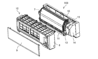
- FIG. 2 is an exploded perspective view showing various components of the indoor unit 103 of the air conditioning apparatus 100 according to Embodiment 1 of the present invention.
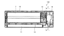
- FIG. 3 is a front view showing the indoor unit 103 of the air conditioning apparatus 100 in a state where the panel 8 according to Embodiment 1 of the present invention is removed.
- the indoor unit 103 of the air conditioning apparatus 100 is a unit of a wall shape of a rectangular parallelepiped shape.
- the indoor unit 103 has an outer shell 12, a grill 9, a box 10, and a housing 12 configured of vanes 11.
- An indoor heat exchanger 7, a drain pan 13, and an electrical item box 14 are provided inside the housing 12 of the indoor unit 103.
- the indoor heat exchanger 7 is disposed from the upper portion to the central portion inside the housing 12 and exchanges heat between water and indoor air.
- the indoor heat exchanger 7 is formed in a mountain-shaped cross-sectional shape from the front side to the back side.
- a fan (not shown) is disposed inside the indoor heat exchanger 7 having a mountain-shaped cross-sectional shape.
- the fan not shown uses a cross flow fan or the like.
- the drain pan 13 is provided below the indoor heat exchanger 7 and receives condensed water generated on the surface of the indoor heat exchanger 7.
- the drain pan 13 has a bottom surface 13 a that receives dew condensation water wider than the horizontal projection area of the indoor heat exchanger 7.
- the bottom surface 13 a of the drain pan 13 is extended below a piping portion 15 which will be described later provided on the right of the front of the indoor heat exchanger 7 in the drawing.
- the drain pan 13 receives condensed water generated from the surfaces of first and second collecting pipes 16 and 17 or a plurality of branch pipes 18 which will be described later disposed in the piping section 15.
- the drain pan 13 receives water discharged from a hose 19 described later disposed in the piping unit 15.
- the drain pan 13 discharges condensed water and the like received on the bottom surface 13 a to the outside of the machine from a discharge port (not shown).
- the electrical component box 14 accommodates therein a control circuit board (not shown) for controlling the indoor unit 103, a control module, and the like in a waterproof and sealed state.
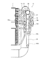
- FIG. 4 is a longitudinal cross-sectional view showing the indoor unit 103 of the air conditioning apparatus 100 from which the panel 8 according to Embodiment 1 of the present invention has been removed, taken along the line ZZ in FIG.
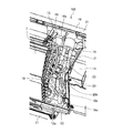
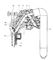
- FIG. 5 is a perspective view which expands and shows the piping part 15 of the indoor unit 103 of the air conditioning apparatus 100 which removed the panel 8 which concerns on Embodiment 1 of this invention.
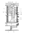
- FIG. 6 is an enlarged front view showing the piping portion 15 of the indoor unit 103 of the air conditioning apparatus 100 from which the panel 8 according to Embodiment 1 of the present invention has been removed.
- a piping unit 15 is provided between the indoor heat exchanger 7 and the electrical component box 14 in the indoor unit 103.
- the piping unit 15 includes an air vent valve 20, a hose 19, a plurality of branch pipes 18, a first collecting pipe 16, a second collecting pipe 17, and a heat insulating pipe 21.
- the air vent valve 20 discharges the air of the water flow path in the water circuit 105 that causes the water to flow through the indoor heat exchanger 7.
- the air vent valve 20 is provided at the front end of the air vent pipe 22 connected to the second collecting pipe 17.
- the hose 19 uses a soft material such as a rubber tube such as a PVC tube, for example, and is flexible.
- the hose 19 is attached to the air vent valve 20.
- the hose 19 extends toward the drain pan 13 receiving the condensed water generated in the indoor heat exchanger 7, avoiding the plurality of branch pipes 18, the first collecting pipe 16 and the second collecting pipe 17.
- the hose 19 discharges the air of the water flow passage in the water circuit 105 together with the water into the drain pan 13 when the air release valve 20 is opened.
- the hose 19 has a double pipe structure whose upper end is fixed to the air vent valve 20. The details of the hose 19 will be described later.
- the plurality of branch pipes 18 supply or discharge water to the indoor heat exchanger 7.
- a part 18 a of the plurality of branch pipes 18 is connected to the indoor heat exchanger 7 and the first collecting pipe 16 and allows water to flow between the indoor heat exchanger 7 and the first collecting pipe 16.
- the other part 18 b of the plurality of branch pipes 18 is connected to the indoor heat exchanger 7 and the second collecting pipe 17, and distributes water between the indoor heat exchanger 7 and the second collecting pipe 17.
- the water cooled by the outdoor unit 101 of the air conditioning apparatus 100 is supplied to the indoor heat exchanger 7 through the first collecting pipe 16 from the part 18a of the plurality of branch pipes 18 . Then, the water heat-exchanged in the indoor heat exchanger 7 is collected in the second collecting pipe 17 from the other part 18 b of the plurality of branch pipes 18.
- Each of the plurality of branch pipes 18 is bent in various ways in the piping portion 15.
- Each of the bent branch pipes 18 connects the connection positions of the indoor heat exchanger 7 with the heat transfer pipes (not shown) as designed.
- the relationship between the hose 19 and the plurality of branch pipes 18 will be described later.
- the first collecting pipe 16 is connected to a portion 18 a of the plurality of branch pipes 18.
- the first collecting pipe 16 distributes the water supplied to the indoor heat exchanger 7 at the time of cooling.
- the first collecting pipe 16 distributes the water heat-exchanged from the indoor heat exchanger 7 at the time of heating.
- the second collecting pipe 17 is connected to another portion 18 b of the plurality of branch pipes 18.
- the second collecting pipe 17 distributes the water discharged from the indoor heat exchanger 7 at the time of cooling.
- the second collecting pipe 17 distributes water to be supplied to the indoor heat exchanger 7 at the time of heating.
- the flow of water may be reversed between cooling and heating.
- the first collecting pipe 16 and the second collecting pipe 17 extend vertically in the front right side of the indoor heat exchanger 7 and are arranged in parallel in a front view. Between the first collecting pipe 16 and the second collecting pipe 17 in a front view, the air vent valve 20 and the hose 19 are located at the center.
- the heat insulating pipe 21 collectively extends the first collecting pipe 16 and the second collecting pipe 17 from the room to the outside.
- the heat insulating pipe 21 is thermally insulated so that the first collecting pipe 16 and the second collecting pipe 17 are not affected by external heat.
- FIG. 7 is a side view showing the air vent valve 20 in the indoor unit 103 of the air conditioning apparatus 100 according to Embodiment 1 of the present invention.
- the air vent valve 20 has a main body 20a, a knob 20b, and an outlet 20c.
- the main body 20 a of the air vent valve 20 is connected to the front end of the air vent pipe 22.
- the knob 20b is integrally provided on the front side of the main body 20a with the valve body 20d rotatably screwed into the main body 20a, and is rotatable.
- the knob 20 b has a display (not shown) for instructing the air release valve 20 to open and close.
- the knob 20b is disc-like, and can be opened or closed by moving the valve body 20d in the front direction or the back direction by rotating it in the positive and reverse circumferential directions.
- the discharge port 20c is provided at the lower end portion of the main body 20a so as to open downward.
- the upper end of the hose 19 is attached to the discharge port 20c.
- FIG. 8 is a side view showing a state in which the hose 19 is fixed to the air vent valve 20 in the indoor unit 103 of the air conditioning apparatus 100 according to Embodiment 1 of the present invention.
- FIG. 9 is a longitudinal sectional view showing a state in which the hose 19 is fixed to the air vent valve 20 in the indoor unit 103 of the air conditioning apparatus 100 according to Embodiment 1 of the present invention.
- the hose 19 has a double pipe structure having a discharge inner pipe 19a and a protective outer pipe 19b.
- the discharge inner pipe 19a and the protective outer pipe 19b are the same flexible members.
- the exhaust inner pipe 19 a is directly inserted into the exhaust port 20 c of the air vent valve 20.
- the protective outer pipe 19 b houses the discharge inner pipe 19 a inside.
- the protective outer pipe 19 b is inserted to the outside of the discharge inner pipe 19 a with respect to the discharge port 20 c of the air vent valve 20.
- a cylindrical air gap 19c is formed between the outer peripheral portion of the discharge inner pipe 19a and the inner peripheral portion of the protective outer pipe 19b.
- the exhaust inner pipe 19 a and the protective outer pipe 19 b are inserted into the exhaust port 20 c of the air vent valve 20 and held.
- the discharge inner pipe 19 a and the protective outer pipe 19 b are fixed to the discharge port 20 c by the binding band 23.
- the discharge inner pipe 19a is fixed to the discharge port 20c by an adhesive
- the protection outer pipe 19b is fixed to the discharge inner pipe 19a by an adhesive.
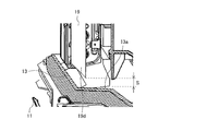
- FIG. 10 is an enlarged vertical cross-sectional view of the end of the lower end portion 19 d of the hose 19 according to Embodiment 1 of the present invention and the drain pan 13.
- the hose 19 has an end face in which the end of the lower end 19d is inclined with respect to the horizontal direction.
- the hose 19 may be an end face parallel to the horizontal direction at the tip of the lower end 19 d.
- the drainage property of the tip of the lower end 19 d of the hose 19 is not good.
- a gap S is formed between the tip of the lower end 19 d of the hose 19 and the bottom surface 13 a of the drain pan 13.
- the gap S is formed to generate a collision sound when the water discharged from the tip of the lower end portion 19 d of the hose 19 collides with the bottom surface 13 a of the drain pan 13.
- FIG. 11 is an enlarged front view showing the hose 19, the plurality of branch pipes 18 and the first and second collecting pipes 16 and 17 according to the first embodiment of the present invention.
- FIG. 12 is an enlarged side view showing the hose 19, the plurality of branch pipes 18, and the first and second collecting pipes 16 and 17 according to the first embodiment of the present invention.
- one branch pipe 18 c of the plurality of branch pipes 18 is bent around the hose 19 to hold the hose 19.
- the branch pipe 18 c holding the hose 19 is located at the lower part of the housing 12. More specifically, the branch pipe 18 c holding the hose 19 extends from the tip of the lower end of the second collecting pipe 17 and uses the lowermost branch pipe 18 of the plurality of branch pipes 18.
- the branch pipe 18c holding the hose 19 is one. However, it is not limited to this.
- the branch pipe 18c holding the hose 19 may be plural.
- the position of the branch pipe 18c holding the hose 19 is not limited.
- the branch pipe 18 c holding the hose 19 is connected to one of the first collecting pipe 16 and the second collecting pipe 17 which is remote from the indoor heat exchanger 7.
- one branch pipe 18 d located at the top of the housing 12 among the plurality of branch pipes 18 is in contact with the hose 19 on the back side of the hose 19.
- the branch pipe 18d in contact with the hose 19 on the back side is in contact with the hose 19 in order to bend in the front side in order to adjust the connection position with the heat transfer pipe of the indoor heat exchanger 7.
- the branch pipe 18c holding the hose 19 is in contact with the branch pipe 18d located at the upper part of the housing 12 to hold the hose 19 with the lower part directed outward, and the lower end in the drain pan 13 It has a 19d tip.
- the air vent valve 20 may be further protruded to the front side so that the hose 19 does not abut on the branch pipe 18 d located at the upper part of the housing 12.
- downsizing of the indoor unit 103 can not be achieved, and this is possible only when there is a sufficient installation space inside the housing 12 of the indoor unit 103.
- the indoor unit 103 of the air conditioner 100 is disposed inside the housing 12 and performs indoor heat exchange as a heat medium heat exchanger that exchanges heat between water as a heat medium and room air.
- the vessel 7 is provided.
- the indoor unit 103 is provided with an air vent valve 20 for discharging the air of the water flow path in the water circuit 105 that causes the water to flow through the indoor heat exchanger 7.
- the indoor unit 103 is provided below the indoor heat exchanger 7 and includes a drain pan 13 that receives condensed water generated on the surface of the indoor heat exchanger 7.
- the indoor unit 103 is attached to the air vent valve 20, and includes a flexible hose 19 in the drain pan 13 for discharging the air in the water flow path together with the water.
- the hose 19 has a double pipe structure whose upper end is fixed to the air vent valve 20.
- the hose 19 has a double pipe structure in which the upper end portion is fixed to the air vent valve 20.
- the rigidity of the hose 19 can be enhanced, and the weight of the hose 19 can be increased. Therefore, the hose 19 is unlikely to be crushed and easily descended downward, and a cross-sectional area necessary for discharging the air can be secured at the lower portion of the hose 19, water is not clogged in the hose 19, and the tip of the lower end 19d of the hose 19 is Water can be discharged smoothly without runaway. Therefore, it is possible to prevent the tip of the lower end portion 19d of the hose 19 from moving wild while maintaining the simple structure of the air releasing hose 19 without adding unnecessary parts.
- the hose 19 can maintain the state in which the other has the upper end fixed to the air vent valve 20. As a result, water is not discharged directly from the outlet 20c of the air vent valve 20 to which the hose 19 is not attached, and the water does not splash around.
- the hose 19 has a double-pipe structure in which the upper end is fixed to the air vent valve 20, even if the hose 19 is bent to avoid a plurality of branch pipes 18 from the upper portion to the lower portion, 2 Of the hose 19 of the heavy pipe structure, only the outer protective outer pipe 19b is deformed, and at least the inner discharge inner pipe 19a can ensure a cross-sectional area necessary for discharging air and water, and the hose 19 does not clog water The tip of the lower end portion 19d of the lower part does not go wild and water can be discharged smoothly.
- the indoor unit 103 of the air conditioner 100 is disposed inside the housing 12 and performs indoor heat exchange as a heat medium heat exchanger that exchanges heat between water as a heat medium and room air.
- the vessel 7 is provided.
- the indoor unit 103 is provided with an air vent valve 20 for discharging the air of the water flow path in the water circuit 105 that causes the water to flow through the indoor heat exchanger 7.
- the indoor unit 103 is provided below the indoor heat exchanger 7 and includes a drain pan 13 that receives condensed water generated on the surface of the indoor heat exchanger 7.
- the indoor unit 103 is attached to the air vent valve 20, and includes a flexible hose 19 in the drain pan 13 for discharging the air in the water flow path together with the water.
- the indoor unit 103 includes a plurality of branch pipes 18 that supply or discharge water to the indoor heat exchanger 7. At least one branch pipe 18 c of the plurality of branch pipes 18 bends around the hose 19 and holds the hose 19.
- At least one branch pipe 18 c bends around the hose 19 and holds the hose 19. Therefore, the cross-sectional area required for the discharge of air and water can be secured at the lower portion of the hose 19, the water does not clog the hose 19, the tip of the lower end portion 19d of the hose 19 does not go out, and the water can be discharged smoothly. . Then, no fixing member is added, and at least one branch pipe 18c performs both the function of circulating water to the indoor heat exchanger 7 and the function of holding the hose 19. Therefore, it is possible to prevent the tip of the lower end portion 19d of the hose 19 from moving wild while maintaining the simple structure of the air releasing hose 19 without adding unnecessary parts.
- a heat medium which is not a refrigerant such as water or brine is supplied to the indoor heat exchanger 7, for example. For this reason, even if at least one branch pipe 18c is bent around the hose 19 and is long so as to surround and hold the hose 19, the thermal efficiency of the designed indoor heat exchanger 7 is not lost.
- the branch pipe 18c holding the hose 19 is located at the lower part of the housing 12.
- the at least one branch pipe 18 c bends around the lower portion of the hose 19 to hold the hose 19. Therefore, a cross-sectional area necessary for discharging air and water can be secured at the lower portion of the hose 19 held by the branch pipe 18c, and the hose 19 is not clogged with water, and the tip of the lower end 19d of the hose 19 does not go wild Water can be discharged smoothly. Then, no fixing member is added, and at least one branch pipe 18c performs both the function of circulating water to the indoor heat exchanger 7 and the function of holding the hose 19. Therefore, it is possible to prevent the tip of the lower end portion 19d of the hose 19 from moving wild while maintaining the simple structure of the air releasing hose 19 without adding unnecessary parts.
- the branch pipe 18d located at the upper part of the housing 12 among the plurality of branch pipes 18 abuts the hose 19 on the back side of the hose 19. .
- the branch pipe 18c holding the hose 19 is in contact with the branch pipe 18d located at the upper part of the housing 12 to hold the hose 19 with the lower part directed outward, and the tip of the lower end 19d in the drain pan 13 Fit.
- the branch pipe 18c holding the hose 19 is held in contact with the branch pipe 18d located at the upper portion of the housing 12 to hold the hose 19 with the lower portion directed outward, Fit the end of the lower end 19d. Therefore, even if the hose 19 directs the lower part outward and directs the tip of the lower end 19 d to the outside of the drain pan 13, the hose 19 is inserted inside the bending point of the branch pipe 18 c holding the hose 19. The hose 19 is forcibly bent so that the end of the lower end 19 d is accommodated in the drain pan 13. As a result, the water does not get clogged in the hose 19, and the tip of the lower end 19d of the hose 19 does not go wild, and the water can be discharged smoothly.
- At least one branch pipe 18c performs both the function of circulating water to the indoor heat exchanger 7 and the function of holding the hose 19. Therefore, it is possible to prevent the tip of the lower end portion 19d of the hose 19 from moving wild while maintaining the simple structure of the air releasing hose 19 without adding unnecessary parts.
- the hose 19 abuts at least at two places of a point in contact with the branch pipe 18 d located in the upper part of the housing 12 and a point inserted in a bent part of the branch pipe 18 c holding the hose 19. . Therefore, the hose 19 can hold the posture more firmly and stably.
- the hose 19 has a double pipe structure in which the upper end is fixed to the air vent valve 20
- the hose 19 of the double pipe structure can be obtained even when the hose 19 necessarily bends from the upper portion to the lower portion.
- the number of the branch pipe 18c holding the hose 19 is one.
- the hose 19 is attached at the final stage in the assembling procedure of the indoor unit 103.
- the hose 19 needs to be inserted into the inside of the bent portion of the branch pipe 18c holding the hose 19. Therefore, if the branch pipe 18c holding the hose 19 is one, the number of times the hose 19 is inserted into the inside of the bent portion of the branch pipe 18c is only one, and the assembly of the indoor unit 103 is easy.
- the indoor unit 103 of the air conditioner 100 is connected to a portion 18 a of the plurality of branch pipes 18 and is discharged from the water supplied to the indoor heat exchanger 7 or the indoor heat exchanger 7.
- a first collecting pipe 16 for circulating water is provided.
- the indoor unit 103 is connected to the other part 18b of the plurality of branch pipes 18, and includes a second collecting pipe 17 for circulating the water discharged from the indoor heat exchanger 7 or the water supplied to the indoor heat exchanger 7. .
- the first collecting pipe 16 and the second collecting pipe 17 extend in the vertical direction on the side of the indoor heat exchanger 7 and are arranged in parallel in a front view.
- the air vent valve 20 and the hose 19 are located between the first collecting pipe 16 and the second collecting pipe 17 in a front view.
- the air vent valve 20 and the hose 19 can be arranged by effectively utilizing the remaining space with respect to the space in which the first collecting pipe 16 and the second collecting pipe 17 are arranged.
- the indoor unit 103 does not become large because the air release valve 20 and the hose 19 are disposed, and the indoor unit 103 can be miniaturized.
- the branch pipe 18c holding the hose 19 is one of the first collecting pipe 16 and the second collecting pipe 17 which is away from the indoor heat exchanger 7. It is connected to the.
- the branch pipe 18 c holding the hose 19 is connected to one of the first collecting pipe 16 and the second collecting pipe 17 which is apart from the indoor heat exchanger 7. Therefore, the branch pipe 18c holding the hose 19 can be extended long while being bent so as to be connected to the indoor heat exchanger 7, and the space inside the indoor unit 103 can be effectively used.
- the hose 19 in the indoor unit 103 of the air conditioner 100, has an end face in which the end of the lower end 19d is inclined with respect to the horizontal direction.
- the end of the inclined end of the lower end portion 19d of the hose 19 is sharp, water is not accumulated, drainage is good, and water can be discharged efficiently.
- a gap S is formed between the tip of the lower end portion 19d of the hose 19 and the bottom surface 13a of the drain pan 13.
- a gap S is formed between the tip of the lower end 19 d of the hose 19 and the bottom surface 13 a of the drain pan 13. For this reason, when the air vent valve 20 is opened and water is discharged from the hose 19, a collision sound is generated when water falling through the gap S collides with the bottom surface 13a of the drain pan 13. As a result, the operator can determine that the air vent valve 20 is open. Therefore, it is possible to prevent the closing of the air release valve 20 and to prevent the wasteful discharge of water.
- the air conditioning apparatus 100 includes the indoor unit 103 of the air conditioning apparatus 100.
- the wall-mounted indoor unit 103 has been described. However, it is not limited to this.
- the indoor unit 103 of the air conditioning apparatus 100 of the present invention can also be applied to a floor-mounted type, a ceiling-embedded type, and the like.
Landscapes
- Engineering & Computer Science (AREA)
- General Engineering & Computer Science (AREA)
- Mechanical Engineering (AREA)
- Chemical & Material Sciences (AREA)
- Combustion & Propulsion (AREA)
- Physics & Mathematics (AREA)
- Thermal Sciences (AREA)
- Devices For Blowing Cold Air, Devices For Blowing Warm Air, And Means For Preventing Water Condensation In Air Conditioning Units (AREA)
- Rigid Pipes And Flexible Pipes (AREA)
Abstract
La présente invention concerne une unité d'intérieur d'un appareil de climatisation, l'unité d'intérieur comprenant : un échangeur de chaleur à agent caloporteur disposé à l'intérieur d'une enveloppe et destiné à effectuer un échange de chaleur entre un agent caloporteur et de l'air intérieur ; une soupape d'évacuation d'air destinée à évacuer, vers l'échangeur de chaleur à agent caloporteur, de l'air présent dans un canal d'écoulement d'agent caloporteur servant à la circulation de l'agent caloporteur ; un bac de récupération placé sous l'échangeur de chaleur à agent caloporteur et destiné à recevoir de l'eau de condensation de rosée produite sur une surface de l'échangeur de chaleur à agent caloporteur ; et un tuyau souple fixé à la soupape d'évacuation d'air et destiné à évacuer l'air présent dans le canal d'écoulement d'agent caloporteur, conjointement avec l'agent caloporteur, vers le bac de récupération, le tuyau présentant une structure à double tube dont la section d'extrémité supérieure est fixée à la soupape d'évacuation d'air.
Priority Applications (5)
| Application Number | Priority Date | Filing Date | Title |
|---|---|---|---|
| PCT/JP2017/044197 WO2019111406A1 (fr) | 2017-12-08 | 2017-12-08 | Unité d'intérieur d'appareil de climatisation, et appareil de climatisation |
| US16/652,529 US11592192B2 (en) | 2017-12-08 | 2017-12-08 | Indoor unit of air-conditioning apparatus and air-conditioning apparatus |
| EP17933984.1A EP3722682B1 (fr) | 2017-12-08 | 2017-12-08 | Unité d'intérieur d'appareil de climatisation, et appareil de climatisation |
| CN201780097446.2A CN111433519A (zh) | 2017-12-08 | 2017-12-08 | 空调装置的室内机以及空调装置 |
| JP2019557970A JP6865854B2 (ja) | 2017-12-08 | 2017-12-08 | 空気調和装置の室内機及び空気調和装置 |
Applications Claiming Priority (1)
| Application Number | Priority Date | Filing Date | Title |
|---|---|---|---|
| PCT/JP2017/044197 WO2019111406A1 (fr) | 2017-12-08 | 2017-12-08 | Unité d'intérieur d'appareil de climatisation, et appareil de climatisation |
Publications (1)
| Publication Number | Publication Date |
|---|---|
| WO2019111406A1 true WO2019111406A1 (fr) | 2019-06-13 |
Family
ID=66750140
Family Applications (1)
| Application Number | Title | Priority Date | Filing Date |
|---|---|---|---|
| PCT/JP2017/044197 Ceased WO2019111406A1 (fr) | 2017-12-08 | 2017-12-08 | Unité d'intérieur d'appareil de climatisation, et appareil de climatisation |
Country Status (5)
| Country | Link |
|---|---|
| US (1) | US11592192B2 (fr) |
| EP (1) | EP3722682B1 (fr) |
| JP (1) | JP6865854B2 (fr) |
| CN (1) | CN111433519A (fr) |
| WO (1) | WO2019111406A1 (fr) |
Cited By (1)
| Publication number | Priority date | Publication date | Assignee | Title |
|---|---|---|---|---|
| US11674741B2 (en) * | 2019-12-20 | 2023-06-13 | Johnson Controls Tyco IP Holdings LLP | Drain spout for drain of HVAC system |
Families Citing this family (2)
| Publication number | Priority date | Publication date | Assignee | Title |
|---|---|---|---|---|
| CN115183610A (zh) * | 2022-07-22 | 2022-10-14 | 睿能太宇(沈阳)能源技术有限公司 | 立式螺旋板换热器 |
| CN116146801B (zh) * | 2023-02-21 | 2025-06-06 | 福州市建筑设计院股份有限公司 | 一种用于空调冷凝水排水的管件组合 |
Citations (8)
| Publication number | Priority date | Publication date | Assignee | Title |
|---|---|---|---|---|
| JPS56126020U (fr) * | 1980-02-27 | 1981-09-25 | ||
| JPS6132894U (ja) * | 1984-07-31 | 1986-02-27 | 史朗 金尾 | ドレ−ンホ−ス |
| JPS6334922U (fr) * | 1986-08-20 | 1988-03-07 | ||
| JPH0277511U (fr) * | 1988-12-01 | 1990-06-14 | ||
| JPH05141690A (ja) * | 1991-11-25 | 1993-06-08 | Sanyo Electric Co Ltd | 空気調和機 |
| JPH06257776A (ja) * | 1993-03-02 | 1994-09-16 | Matsushita Electric Ind Co Ltd | ドレンホース |
| JPH09210392A (ja) | 1996-01-30 | 1997-08-12 | Daikin Ind Ltd | ファンコイルユニット |
| US20170227250A1 (en) * | 2002-03-06 | 2017-08-10 | John Chris Karamanos | Embedded heat exchanger with support mechanism |
Family Cites Families (11)
| Publication number | Priority date | Publication date | Assignee | Title |
|---|---|---|---|---|
| JPS6132984U (ja) * | 1984-07-31 | 1986-02-27 | 株式会社島津製作所 | Ect用放射線検出器 |
| DE202005010328U1 (de) * | 2005-07-01 | 2005-09-15 | Da Kunststoff Gmbh | Vorrichtung zum Verbinden einer medienführenden Anschlussleitung an eine Hauseinführung |
| WO2011083519A1 (fr) * | 2010-01-08 | 2011-07-14 | ダイキン工業株式会社 | Dispositif d'évacuation d'air, unité d'échange de chaleur et outil de fixation |
| DE202010010532U1 (de) * | 2010-07-22 | 2010-10-21 | Reventa Gmbh & Co. Kg | Luftführungsrohr |
| US20180045343A1 (en) * | 2010-10-19 | 2018-02-15 | Contitech Techno-Chemie Gmbh | Fluid resistant high temperature hose |
| US20120247601A1 (en) * | 2011-03-28 | 2012-10-04 | Glenn Allen Ayers | Flexible Hose During Pressurization |
| CN202083046U (zh) | 2011-05-26 | 2011-12-21 | 姜鉴明 | 高效逆流同程盘管式换热器 |
| JP2012247131A (ja) | 2011-05-27 | 2012-12-13 | Mitsubishi Electric Corp | 空気調和機 |
| CN202220913U (zh) | 2011-08-18 | 2012-05-16 | 永亨控股集团有限公司 | 一种frpp高强度加筋管 |
| CN205534654U (zh) | 2016-04-20 | 2016-08-31 | 浙江光通塑业有限公司 | 一种塑料排水管 |
| CN206591743U (zh) | 2017-01-17 | 2017-10-27 | 深圳市清华苑建筑与规划设计研究有限公司 | 一种大进深大尺度砼屋面建筑找坡屋面排水构造 |
-
2017
- 2017-12-08 WO PCT/JP2017/044197 patent/WO2019111406A1/fr not_active Ceased
- 2017-12-08 EP EP17933984.1A patent/EP3722682B1/fr active Active
- 2017-12-08 US US16/652,529 patent/US11592192B2/en active Active
- 2017-12-08 CN CN201780097446.2A patent/CN111433519A/zh active Pending
- 2017-12-08 JP JP2019557970A patent/JP6865854B2/ja not_active Expired - Fee Related
Patent Citations (8)
| Publication number | Priority date | Publication date | Assignee | Title |
|---|---|---|---|---|
| JPS56126020U (fr) * | 1980-02-27 | 1981-09-25 | ||
| JPS6132894U (ja) * | 1984-07-31 | 1986-02-27 | 史朗 金尾 | ドレ−ンホ−ス |
| JPS6334922U (fr) * | 1986-08-20 | 1988-03-07 | ||
| JPH0277511U (fr) * | 1988-12-01 | 1990-06-14 | ||
| JPH05141690A (ja) * | 1991-11-25 | 1993-06-08 | Sanyo Electric Co Ltd | 空気調和機 |
| JPH06257776A (ja) * | 1993-03-02 | 1994-09-16 | Matsushita Electric Ind Co Ltd | ドレンホース |
| JPH09210392A (ja) | 1996-01-30 | 1997-08-12 | Daikin Ind Ltd | ファンコイルユニット |
| US20170227250A1 (en) * | 2002-03-06 | 2017-08-10 | John Chris Karamanos | Embedded heat exchanger with support mechanism |
Cited By (1)
| Publication number | Priority date | Publication date | Assignee | Title |
|---|---|---|---|---|
| US11674741B2 (en) * | 2019-12-20 | 2023-06-13 | Johnson Controls Tyco IP Holdings LLP | Drain spout for drain of HVAC system |
Also Published As
| Publication number | Publication date |
|---|---|
| JPWO2019111406A1 (ja) | 2020-07-09 |
| EP3722682A4 (fr) | 2020-11-25 |
| JP6865854B2 (ja) | 2021-04-28 |
| US11592192B2 (en) | 2023-02-28 |
| EP3722682B1 (fr) | 2023-10-11 |
| US20200240651A1 (en) | 2020-07-30 |
| EP3722682A1 (fr) | 2020-10-14 |
| CN111433519A (zh) | 2020-07-17 |
Similar Documents
| Publication | Publication Date | Title |
|---|---|---|
| CN104379999B (zh) | 空调装置以及空调装置的安装结构 | |
| CN105008809B (zh) | 空调机的室内机组 | |
| CN107076433B (zh) | 室外机 | |
| JP6305619B2 (ja) | 室外機 | |
| KR102466274B1 (ko) | 공기조화기 | |
| JP6865854B2 (ja) | 空気調和装置の室内機及び空気調和装置 | |
| JP3669337B2 (ja) | 空気調和機の室外空調ユニット | |
| JP7453596B2 (ja) | 室内機および空気調和機 | |
| CN110366663A (zh) | 空调机的室内机 | |
| JP5123018B2 (ja) | 空調装置 | |
| CN107076432A (zh) | 室内机及制冷循环装置 | |
| CN111148947B (zh) | 空调装置的室内机以及空调装置 | |
| EP3851758A1 (fr) | Climatiseur | |
| JP4702273B2 (ja) | 空気調和装置の断熱配管構造 | |
| WO2018025325A1 (fr) | Unité extérieure, dispositif de climatisation et procédé de fabrication de poignée d'unité extérieure | |
| EP3296649A1 (fr) | Dispositif de climatisation | |
| EP1970638A1 (fr) | Climatiseur | |
| JP4213725B2 (ja) | 空気調和装置 | |
| CN212408877U (zh) | 一种空调室内机 | |
| JP2003222366A (ja) | 室内ユニット及び空気調和機 | |
| JP6227167B2 (ja) | 室外機 | |
| JP2791711B2 (ja) | 空気調和装置 | |
| JP2017083141A (ja) | 空気調和機 | |
| WO2021199155A1 (fr) | Unité extérieure pour dispositif de climatisation | |
| JP2009243840A (ja) | 室内ユニットおよび空気調和装置 |
Legal Events
| Date | Code | Title | Description |
|---|---|---|---|
| 121 | Ep: the epo has been informed by wipo that ep was designated in this application |
Ref document number: 17933984 Country of ref document: EP Kind code of ref document: A1 |
|
| ENP | Entry into the national phase |
Ref document number: 2019557970 Country of ref document: JP Kind code of ref document: A |
|
| NENP | Non-entry into the national phase |
Ref country code: DE |
|
| ENP | Entry into the national phase |
Ref document number: 2017933984 Country of ref document: EP Effective date: 20200708 |