WO2019111428A1 - Machine de traitement laser - Google Patents
Machine de traitement laser Download PDFInfo
- Publication number
- WO2019111428A1 WO2019111428A1 PCT/JP2018/013953 JP2018013953W WO2019111428A1 WO 2019111428 A1 WO2019111428 A1 WO 2019111428A1 JP 2018013953 W JP2018013953 W JP 2018013953W WO 2019111428 A1 WO2019111428 A1 WO 2019111428A1
- Authority
- WO
- WIPO (PCT)
- Prior art keywords
- cooling
- main body
- cooling medium
- laser
- processing machine
- Prior art date
- Legal status (The legal status is an assumption and is not a legal conclusion. Google has not performed a legal analysis and makes no representation as to the accuracy of the status listed.)
- Ceased
Links
Images


Classifications
-
- H—ELECTRICITY
- H01—ELECTRIC ELEMENTS
- H01S—DEVICES USING THE PROCESS OF LIGHT AMPLIFICATION BY STIMULATED EMISSION OF RADIATION [LASER] TO AMPLIFY OR GENERATE LIGHT; DEVICES USING STIMULATED EMISSION OF ELECTROMAGNETIC RADIATION IN WAVE RANGES OTHER THAN OPTICAL
- H01S3/00—Lasers, i.e. devices using stimulated emission of electromagnetic radiation in the infrared, visible or ultraviolet wave range
- H01S3/02—Constructional details
- H01S3/04—Arrangements for thermal management
- H01S3/0404—Air- or gas cooling, e.g. by dry nitrogen
-
- B—PERFORMING OPERATIONS; TRANSPORTING
- B23—MACHINE TOOLS; METAL-WORKING NOT OTHERWISE PROVIDED FOR
- B23K—SOLDERING OR UNSOLDERING; WELDING; CLADDING OR PLATING BY SOLDERING OR WELDING; CUTTING BY APPLYING HEAT LOCALLY, e.g. FLAME CUTTING; WORKING BY LASER BEAM
- B23K26/00—Working by laser beam, e.g. welding, cutting or boring
- B23K26/70—Auxiliary operations or equipment
-
- H—ELECTRICITY
- H01—ELECTRIC ELEMENTS
- H01S—DEVICES USING THE PROCESS OF LIGHT AMPLIFICATION BY STIMULATED EMISSION OF RADIATION [LASER] TO AMPLIFY OR GENERATE LIGHT; DEVICES USING STIMULATED EMISSION OF ELECTROMAGNETIC RADIATION IN WAVE RANGES OTHER THAN OPTICAL
- H01S3/00—Lasers, i.e. devices using stimulated emission of electromagnetic radiation in the infrared, visible or ultraviolet wave range
- H01S3/02—Constructional details
- H01S3/04—Arrangements for thermal management
- H01S3/0405—Conductive cooling, e.g. by heat sinks or thermo-electric elements
-
- H—ELECTRICITY
- H01—ELECTRIC ELEMENTS
- H01S—DEVICES USING THE PROCESS OF LIGHT AMPLIFICATION BY STIMULATED EMISSION OF RADIATION [LASER] TO AMPLIFY OR GENERATE LIGHT; DEVICES USING STIMULATED EMISSION OF ELECTROMAGNETIC RADIATION IN WAVE RANGES OTHER THAN OPTICAL
- H01S3/00—Lasers, i.e. devices using stimulated emission of electromagnetic radiation in the infrared, visible or ultraviolet wave range
- H01S3/02—Constructional details
- H01S3/04—Arrangements for thermal management
- H01S3/0407—Liquid cooling, e.g. by water
-
- H—ELECTRICITY
- H01—ELECTRIC ELEMENTS
- H01S—DEVICES USING THE PROCESS OF LIGHT AMPLIFICATION BY STIMULATED EMISSION OF RADIATION [LASER] TO AMPLIFY OR GENERATE LIGHT; DEVICES USING STIMULATED EMISSION OF ELECTROMAGNETIC RADIATION IN WAVE RANGES OTHER THAN OPTICAL
- H01S3/00—Lasers, i.e. devices using stimulated emission of electromagnetic radiation in the infrared, visible or ultraviolet wave range
- H01S3/14—Lasers, i.e. devices using stimulated emission of electromagnetic radiation in the infrared, visible or ultraviolet wave range characterised by the material used as the active medium
- H01S3/22—Gases
- H01S3/223—Gases the active gas being polyatomic, i.e. containing two or more atoms
- H01S3/2232—Carbon dioxide (CO2) or monoxide [CO]
-
- H—ELECTRICITY
- H01—ELECTRIC ELEMENTS
- H01S—DEVICES USING THE PROCESS OF LIGHT AMPLIFICATION BY STIMULATED EMISSION OF RADIATION [LASER] TO AMPLIFY OR GENERATE LIGHT; DEVICES USING STIMULATED EMISSION OF ELECTROMAGNETIC RADIATION IN WAVE RANGES OTHER THAN OPTICAL
- H01S3/00—Lasers, i.e. devices using stimulated emission of electromagnetic radiation in the infrared, visible or ultraviolet wave range
- H01S3/02—Constructional details
- H01S3/03—Constructional details of gas laser discharge tubes
Definitions
- the present invention relates to a small-sized home-use laser beam machine.
- a laser processing machine that cuts a sheet metal by laser irradiation is known.
- the temperature of the laser oscillator is high. Therefore, for example, the gas is used as a cooling medium to cool the laser oscillator, and the gas as the cooling medium is cooled by the Peltier device (see, for example, Patent Document 1).
- the Peltier device While cooling the cooling medium using the Peltier device as described above, the Peltier device generates heat. For this reason, it is not practical to arrange a Peltier element in a small-sized apparatus that can be used at home and to cool the cooling medium for cooling the laser oscillator.
- An object of the present invention is to provide a laser processing machine in which a Peltier element for cooling a cooling medium for cooling a laser oscillator is incorporated in the apparatus main body of a small household laser processing machine.
- an apparatus main body a laser oscillator housed inside the apparatus main body, a cooling medium flow passage disposed inside the apparatus main body for circulating a cooling medium for cooling the laser oscillator, and And a cooling device provided with a Peltier element for cooling a cooling medium flowing through the cooling medium flow path, wherein the cooling device is connected with a radiation fin for radiating heat generated in the Peltier element, and the radiation fin
- the present invention relates to a laser beam machine disposed immediately upstream of the exhaust port in a flow of air flowing to an exhaust port for discharging air inside the apparatus body to the outside of the apparatus body.
- a filter be fixed to a portion on the upstream side of the radiation fin in the flow of the air.
- the storage part which stores the said cooling medium is provided in the inside of the said apparatus main body.
- the device body has a rectangular parallelepiped shape, and the laser oscillator, the cooling medium flow passage, the cooling device, the heat radiation fin, and the storage portion are at the back of the device body in which the exhaust port is formed. It is preferable to be arranged along the wall.
- a laser beam machine in which a Peltier element for cooling a cooling medium for cooling a laser oscillator is incorporated in the main body of a small household laser beam machine.
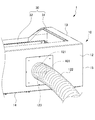
- FIG. 1 is a front perspective view showing a laser beam machine according to a first embodiment of the present invention. It is a rear perspective view showing a laser beam machine by a 1st embodiment of the present invention. It is a principal part perspective view showing arrangement of a channel of a cooling medium of a laser beam machine by a 1st embodiment of the present invention. It is a principal part perspective view showing signs that a filter of a laser beam machine by a 1st embodiment of the present invention was removed. It is a principal part bottom view showing a cooling device of a laser beam machine by a 1st embodiment of the present invention. It is a block diagram showing a channel of a cooling medium of a laser beam machine by a 1st embodiment of the present invention.
- Laser processing machine 1 is capable of performing laser processing for various materials as paper or acryl, a laser processing machine 1 using the CO 2 laser that can be used in the home with small.
- the laser processing machine 1 includes an apparatus body 10, a laser oscillator 71, a cooling medium channel 420, and a cooling device 45.
- the direction from the back wall 12 to the front wall 11 of the apparatus main body 10 is defined as the front direction
- the opposite direction is defined as the back direction
- these are defined as the front and back direction.
- the opposite direction is defined as the right direction, and these are defined as the left and right direction.
- the direction from the lower wall 14 to the upper wall 13 in FIG. 1 is defined as the upward direction
- the opposite direction is defined as the downward direction, and these are defined as the upward and downward direction.
- the apparatus main body 10 is configured in a rectangular parallelepiped shape, and has a front wall 11, a back wall 12, an upper wall 13, a lower wall 14, a first side wall 15, and a second side wall 16, as shown in FIG.
- the back wall 12, the upper wall 13, the lower wall 14, the first side wall 15, and the second side wall 16 are configured by coating a sheet metal made of aluminum alloy or the like.
- the first side wall 15 and the second side wall 16 face each other, and the upper wall 13 and the lower wall 14 face each other.
- the lower end of the front wall 11, the lower end of the back wall 12, the lower end of the first side wall 15, and the lower end of the second side wall 16 are all connected to the lower wall 14.
- a main body opening 101 is formed in a portion on the front side of the upper wall 13 over the upper portion of the front wall 11.
- An upper lid 132 is rotatably supported relative to the upper wall 13 at a rear portion of the upper wall 13 via a pair of hinges 131.
- the upper lid 132 has substantially the same shape as the main body opening, and can close the main body opening.
- An inner processing space 102 is formed.
- a workpiece to be laser-processed is placed and laser-processed.
- An exhaust port 121 is formed in the back wall 12 as shown in FIG.
- the exhaust port 121 has a diameter of about 10 cm, is formed of a circular through hole penetrating the back wall 12, and is formed slightly to the left of the center of the back wall 12 in the left-right direction.
- One end of a hose 122 is connected to the outside of the back wall 12 of the exhaust port 121.
- a blower (not shown) is connected to the other end of the hose 122, and while the laser irradiation is being performed, the blower is driven, air is sucked into the processing space 102 by the blower, and the outside of the processing space 102 is Discharge to
- a shielding plate 123 is provided inside the apparatus main body 10 and at a position facing the through hole.
- the shielding plate 123 is disposed to close the substantially upper half of the exhaust port 121, and the laser light leaks from the processing space 102 to the outside of the apparatus main body 10 through the space between the fins 621 described later by the shielding plate 123.
- the substantially lower half of the exhaust port 121 is opposed to the back plate 401 of the lower case 40 described later.
- the back plate 401 and the shielding plate 123 of the lower case 40 are separated in the front-rear direction.
- a guide rail 30 is provided in the processing space 102.
- the guide rails 30 extend in the left-right direction and extend in the left-right direction with the front-rear direction rails 31 respectively disposed at the left and right ends of the processing space 102.
- a rail 32 is provided.
- the left and right direction rail 32 is movable in the front and rear direction with respect to the front and rear direction rail 31 while maintaining the positional relationship parallel to the left and right direction.
- the left and right direction rail 32 is provided with a processed portion facing portion 33 movable along the left and right direction rail 32.
- a mirror is provided in the processing portion facing portion 33, and the laser light emitted from the laser oscillator 71 is reflected to irradiate the processing object with the laser light.
- the lateral rail 32 and the workpiece facing part 33 are driven and moved by a motor (not shown) so that the laser is irradiated to a predetermined position of the workpiece.
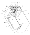
- a lower case 40 having a rectangular parallelepiped shape made of metal, a heat radiating portion 60, and an oscillator case 70 are provided inside the processing space 102 and in the vicinity of the back wall 12, as shown in FIG. 3, a lower case 40 having a rectangular parallelepiped shape made of metal, a heat radiating portion 60, and an oscillator case 70 are provided. It is provided along the back wall 12 in this order from 14 upwards.
- a laser oscillator 71 is housed in the oscillator case 70.
- the laser oscillator 71 is composed of a glass high voltage excitation laser oscillator that emits a CO 2 laser.
- the laser oscillator 71 is supported by a pair of pedestals 72 and is supported inside a metal rectangular parallelepiped oscillator case 70.
- the laser oscillator 71 has a cylindrical shape, and is constituted by a glass tube disposed concentrically and threefold around the axial center of the laser oscillator 71.
- gases such as CO 2 , nitrogen (N 2 ), helium (He), etc. circulate in the space near the center 1 and the space outside the center, respectively. .
- cooling water as a cooling medium composed of a coolant or the like flows from the left end to the right end of the laser oscillator 71 to cool the laser oscillator 71.
- the lower case 40 is fixed to the lower wall 14.
- a power supply unit 41 a cooling water storage tank 42, and a temperature control board 43 are accommodated.
- the cooling water storage tank 42 as a storage section for storing a cooling medium is made of acrylic and has a rectangular parallelepiped shape, and the entire outer side is covered with a heat insulating sponge, and the lower wall 14 of the right portion of the lower case 40 It is fixed to
- the cooling water storage tank 42 is not limited to acrylic, and may be made of a material that does not leak water. In the cooling water storage tank 42, several 100 mL (milliliter) of cooling water such as coolant liquid is stored.
- a pipe member 421 for supplying cooled cooling water to the left end of the laser oscillator 71 is connected to the cooling water storage tank 42, and the processing space 102 is shielded in the middle of the pipe member 421.
- a water circulation pump 422 having a flow sensor is provided between the second inner wall 16 and the second side wall 16 (in the side panel).
- the other end of the tube member 421 is connected to the left end of the laser oscillator 71.
- the cooling water from the cooling water storage tank 42 is configured to flow to the laser oscillator 71 by driving the water circulation pump 422.
- one end portion of a pipe member 423 for circulating the cooling water whose temperature has been increased by the laser oscillator 71 from the right end portion of the laser oscillator 71 to the cooling water storage tank 42 is connected to the cooling water storage tank 42.
- the other end of 423 is connected to the right end of the laser oscillator 71.
- the power supply unit 41 has a rectangular parallelepiped shape, and is fixed to the bottom of the left portion of the lower case 40.
- the power supply unit 41 includes a power supply circuit that supplies the temperature control substrate 43, the laser oscillator 71, and the like with voltage reduction and boosting and stabilization of electricity supplied from the outside.
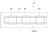
- a cooling device 45 is provided in the lower case 40 and above the power supply unit 41.
- the cooling device 45 includes a metal cooling case 451 having a rectangular parallelepiped shape, and a Peltier element 452 provided inside the cooling case 451.
- Three Peltier elements 452 are provided, each having a square plate shape with a side of 3 cm, and arranged in a straight line.
- a pipe member 454 for circulating the cooling water is disposed inside the cooling case 451.
- the pipe member 454 extends from the right end to the left end of the cooling case 451 so as to face the three Peltier elements 452, is folded at the right end to the left end of the cooling case 451, and extends from the left end to the right end of the cooling case 451.
- the three Peltier elements 452 respectively extend toward the portion to reach the right end of the cooling case 451.
- One end and the other end of the pipe member are respectively extended and connected to the cooling water storage tank 42, and the coolant whose temperature has risen is circulated through the pipe member 454 to a position facing the Peltier element 452.
- the cooled and cooled cooling water is configured to be returned to the cooling water storage tank 42 through the pipe member 454.
- the pipe members 454, 421, 423 constitute the cooling medium channel 420.
- a temperature control board 43 is provided on the upper portion of the left end portion of the lower case 40.
- the temperature control board 43 is fixed to the upper plate of the left end portion of the lower case 40, and is electrically connected to a temperature sensor (not shown) provided on the board of the cooling device 45 to which the Peltier element 452 is fixed. .
- a temperature sensor not shown
- laser irradiation is stopped and cooling by the Peltier device 452 Is controlled by the temperature control board 43.
- the temperature control board 43 is electrically connected to a temperature sensor (not shown) provided in the cooling water storage tank 42. Control by which the Peltier element 452 starts cooling by the temperature sensor (not shown) so that the cooling water is cooled when the temperature of the cooling water above the cooling water storage tank 42 exceeds a second predetermined temperature Is performed by the temperature control board 43.
- the heat radiating portion 60 is fixed to the upper plate of the lower case 40.
- the heat radiating portion 60 includes a plate member 61, a heat sink 62, and a filter 63.
- the plate member 61 is formed in a substantially rectangular parallelepiped shape opened in the front-rear direction by bending a metal plate.
- the lower end portion of the plate member 61 is fixed to the upper plate of the lower case 40, and the upper plate of the lower case 40 and the plate member 61 form a heat sink accommodation space.
- the heat sink 62 is integrally connected to and fixed to the plate surface of the lower case 40 so as to be thermally conductive.
- the heat sink 62 is composed of a large number of thin metal fins 621 parallel in the front-rear direction and the top-bottom direction. Since the fins 621, the upper plate of the lower case 40 and the Peltier device 452 are all made of metal, the heat generated by the Peltier device 452 is transferred to the fins 621 through the upper plate of the lower case 40. As such, the heat transfer efficiency is configured to be high.
- the filter 63 is fixed to the front surface of the fin 621 so as to cover the entire front surface of the fin 621.
- the filter 63 prevents debris, powder or the like generated by laser processing from entering between the large number of fins 621.
- the rear side of the fin 621 is opposed to the exhaust port 121 of the back wall 12 via the shielding plate 123. With this configuration, the fins 621 are disposed immediately upstream of the exhaust port 121 in the flow of air flowing to the exhaust port 121 for discharging the air inside the apparatus main body 10 to the outside of the apparatus main body 10. And the filter 63 is being fixed in the upstream part of the fin 621 in the flow of the said air.
- directly upstream means immediately upstream of the exhaust port 121 except for the shielding plate 123 which is indispensable to prevent the laser light in the processing space 102 from leaking out of the apparatus main body 10.
- the shielding plate 123 which is indispensable to prevent the laser light in the processing space 102 from leaking out of the apparatus main body 10.
- the fins 621 are located extremely near the exhaust port 121, there is nothing other than the shielding plate 123, and the distance between the fins 621 and the exhaust port 121 is also It means very close. Therefore, for example, when the power supply unit 41, the temperature control board 43, and the like are present between the fins 621 and the exhaust port 121, it means that it does not correspond to "immediately upstream.”
- the operation of cooling the cooling water by the Peltier element 452 is as follows.
- the temperature control board 43 controls the water circulation pump 422 to drive the cooling water of the cooling water storage tank 42,
- the laser oscillator 71 is supplied through the pipe member 421.
- the cooling water whose temperature has risen by cooling the laser oscillator 71 flows through the pipe member 423 disposed so as to penetrate the cooling water storage tank 42 to the pipe member 454 disposed in the cooling device 45.
- the cooling water in the pipe member 454 is cooled by the Peltier element 452 in the cooling device 45.
- the laser processing machine 1 having the above-described configuration can exhibit the following effects.
- the laser beam machine 1 is disposed in the apparatus body 10, the laser oscillator 71 housed inside the apparatus body 10, and the apparatus body 10 for circulating a cooling medium for cooling the laser oscillator 71.
- the cooling medium passage 420 and the cooling device 45 provided with the Peltier element 452 for cooling the cooling medium flowing through the cooling medium passage 420 are provided.
- the cooling device 45 is connected to a fin 621 for radiating the heat generated in the Peltier element 452, and the fin 621 is an air flowing to the exhaust port 121 for discharging the air inside the device body 10 to the outside of the device body 10.
- the air discharged from the processing space 102 to the outside of the apparatus body 10 through the exhaust port 121 is used to cool the cooling water while generating heat from the Peltier element 452 outside the apparatus body 10. It is possible to release it. Therefore, the Peltier element 452 can be disposed inside the apparatus main body 10 and used to cool the cooling water. For this reason, even when the ambient temperature around the laser processing machine 1 is high by 40 ° C. or the like, the cooling water can be cooled to a temperature such as 20 ° C., and the laser processing can be performed.
- a filter 63 is fixed to a portion on the upstream side of the radiation fin 621 in the flow of air.
- a cooling water storage tank 42 as a storage unit for storing a cooling medium is provided inside the apparatus main body 10. With this configuration, it is not necessary to provide a storage unit for storing the cooling medium outside the apparatus main body 10, and the configuration for driving the laser processing machine 1 can be made compact.
- the laser processing machine according to the second embodiment of the present invention differs from the laser processing machine 1 according to the first embodiment in the configuration of the lower case 40A from the configuration of the lower case 40 in the first embodiment.
- the configuration other than this is the same as the configuration in the first embodiment, so the same reference numerals are given and the description is omitted.
- the lower case 40A has a rectangular parallelepiped shape formed by bending an integrally formed metal plate.
- a recessed portion is formed in a leftward portion of the upper portion of the box-like member, and the heat radiating portion 60A is provided in the recessed portion so as to be fitted therein.
- a filter 63 is provided at the front end, and a fin 621 is provided at the rear side.
- a cooling water storage tank 42A is disposed in the lower case 40A and below the heat radiating portion 60A.
- the power supply unit 41A is disposed on the right side of the heat radiation unit 60A.
- a temperature control board 43A is disposed in the lower case 40A and below the power supply unit 41A.
- the cooling device 45 is disposed in the lower case 40A and below the heat radiating portion 60A, and is fixed to the upper plate of the lower case 40A so as to be thermally conductive.
- the present invention is not limited to the above-described embodiment, and can be implemented in various forms within the scope of the claims.
- the number, arrangement, and dimensions of the Peltier devices in the cooling device are not limited to the number, arrangement, and dimensions of the Peltier devices 452 in this embodiment.
- the shape, configuration, and the like of each portion are not limited to the shape, configuration, and the like of each portion in the present embodiment.
Landscapes
- Physics & Mathematics (AREA)
- Electromagnetism (AREA)
- Engineering & Computer Science (AREA)
- Optics & Photonics (AREA)
- Plasma & Fusion (AREA)
- Mechanical Engineering (AREA)
- Chemical & Material Sciences (AREA)
- Chemical Kinetics & Catalysis (AREA)
- Lasers (AREA)
- Laser Beam Processing (AREA)
Abstract
L'objectif de l'invention est de proposer une machine de traitement laser ayant, intégré dans le corps principal de dispositif d'une petite machine de traitement laser à usage domestique, un élément Peltier qui refroidit un milieu de refroidissement pour refroidir un oscillateur laser. La machine de traitement laser 1 comprend : le corps principal de dispositif 10 ; un oscillateur laser 71 logé à l'intérieur du corps principal de dispositif 10 ; un trajet d'écoulement de milieu de refroidissement disposé à l'intérieur du corps principal de dispositif 10, à travers lequel circule le milieu de refroidissement pour refroidir l'oscillateur laser 71 ; et un dispositif de refroidissement 45 pourvu d'un élément Peltier pour refroidir le milieu de refroidissement circulant dans le trajet d'écoulement de milieu de refroidissement. Le dispositif de refroidissement 45 est connecté à des ailettes de rayonnement thermique 621 pour rayonner thermiquement la chaleur générée dans l'élément Peltier. Un orifice d'échappement 121 évacue l'air à l'intérieur du corps principal de dispositif 10 vers l'extérieur du corps principal de dispositif 10, et les ailettes de rayonnement thermique 621 sont disposées sur le côté directement en amont de l'orifice d'échappement 121 dans le contexte de l'écoulement d'air vers l'orifice d'échappement 121.
Priority Applications (2)
| Application Number | Priority Date | Filing Date | Title |
|---|---|---|---|
| CN201880005769.9A CN110168821B (zh) | 2017-12-05 | 2018-03-30 | 激光加工机 |
| US16/494,783 US10903616B2 (en) | 2017-12-05 | 2018-03-30 | Laser processing machine |
Applications Claiming Priority (2)
| Application Number | Priority Date | Filing Date | Title |
|---|---|---|---|
| JP2017233147A JP6446118B1 (ja) | 2017-12-05 | 2017-12-05 | レーザー加工機 |
| JP2017-233147 | 2017-12-05 |
Publications (1)
| Publication Number | Publication Date |
|---|---|
| WO2019111428A1 true WO2019111428A1 (fr) | 2019-06-13 |
Family
ID=64899480
Family Applications (1)
| Application Number | Title | Priority Date | Filing Date |
|---|---|---|---|
| PCT/JP2018/013953 Ceased WO2019111428A1 (fr) | 2017-12-05 | 2018-03-30 | Machine de traitement laser |
Country Status (4)
| Country | Link |
|---|---|
| US (1) | US10903616B2 (fr) |
| JP (1) | JP6446118B1 (fr) |
| CN (1) | CN110168821B (fr) |
| WO (1) | WO2019111428A1 (fr) |
Families Citing this family (2)
| Publication number | Priority date | Publication date | Assignee | Title |
|---|---|---|---|---|
| CN111922530A (zh) * | 2020-08-09 | 2020-11-13 | 刘琳 | 一种纺织面料用高散热型激光切割机切割方法 |
| CN113182695A (zh) * | 2021-03-29 | 2021-07-30 | 张闪闪 | 一种模具花纹加工用激光蚀刻设备 |
Citations (8)
| Publication number | Priority date | Publication date | Assignee | Title |
|---|---|---|---|---|
| JPH0270469U (fr) * | 1988-11-17 | 1990-05-29 | ||
| JPH0760474A (ja) * | 1993-08-30 | 1995-03-07 | Mitsubishi Electric Corp | レーザ加工装置 |
| US5608748A (en) * | 1994-10-20 | 1997-03-04 | Carl Zeiss Stiftung | Cooling device for a pulsed laser and process for the operation of such a cooling device |
| JPH09122946A (ja) * | 1995-10-31 | 1997-05-13 | Hitachi Cable Ltd | 炭酸ガスレーザ光を用いた基板の加工方法およびその加工装置 |
| JPH09186379A (ja) * | 1996-01-04 | 1997-07-15 | Miyachi Technos Corp | レーザ冷却用熱交換器及びレーザ装置 |
| JP2009224487A (ja) * | 2008-03-14 | 2009-10-01 | Fanuc Ltd | ガスレーザ発振器のベーキング方法 |
| JP2012222242A (ja) * | 2011-04-12 | 2012-11-12 | Panasonic Industrial Devices Sunx Co Ltd | レーザ加工装置及びレーザ加工システム |
| WO2016084825A1 (fr) * | 2014-11-28 | 2016-06-02 | ブラザー工業株式会社 | Dispositif d'usinage laser et procédé d'usinage laser |
Family Cites Families (10)
| Publication number | Priority date | Publication date | Assignee | Title |
|---|---|---|---|---|
| JP2517655B2 (ja) | 1988-09-06 | 1996-07-24 | 三菱電機株式会社 | インクシ―ト巻取駆動装置 |
| JP2004347137A (ja) * | 2003-05-19 | 2004-12-09 | Keyence Corp | ペルチェ素子の固定方法及び冷却装置ならびにレーザ発振器 |
| JP2004354780A (ja) * | 2003-05-29 | 2004-12-16 | Keyence Corp | レーザ加工装置 |
| JP5299372B2 (ja) * | 2010-07-23 | 2013-09-25 | 三菱電機株式会社 | 電子機器 |
| JP5053447B1 (ja) * | 2011-03-22 | 2012-10-17 | ファナック株式会社 | 筐体内冷却用熱交換器 |
| JP2015114369A (ja) * | 2013-12-09 | 2015-06-22 | カシオ計算機株式会社 | 投影装置 |
| JP6215857B2 (ja) * | 2015-02-26 | 2017-10-18 | ファナック株式会社 | 放熱フィンを有するl字状熱伝導部材を備えた空冷式レーザ装置 |
| JP6166310B2 (ja) * | 2015-06-11 | 2017-07-19 | ファナック株式会社 | レーザ発振部、空気冷却機、および除湿器を共通の冷却水にて冷却するレーザ装置 |
| EP3410549B1 (fr) * | 2016-01-26 | 2022-08-31 | FUJIFILM Corporation | Dispositif laser |
| JP6687663B2 (ja) * | 2018-04-12 | 2020-04-28 | ファナック株式会社 | 筐体の内部の熱を外部に放出する熱移動装置を備えるレーザ装置 |
-
2017
- 2017-12-05 JP JP2017233147A patent/JP6446118B1/ja active Active
-
2018
- 2018-03-30 US US16/494,783 patent/US10903616B2/en active Active
- 2018-03-30 CN CN201880005769.9A patent/CN110168821B/zh active Active
- 2018-03-30 WO PCT/JP2018/013953 patent/WO2019111428A1/fr not_active Ceased
Patent Citations (8)
| Publication number | Priority date | Publication date | Assignee | Title |
|---|---|---|---|---|
| JPH0270469U (fr) * | 1988-11-17 | 1990-05-29 | ||
| JPH0760474A (ja) * | 1993-08-30 | 1995-03-07 | Mitsubishi Electric Corp | レーザ加工装置 |
| US5608748A (en) * | 1994-10-20 | 1997-03-04 | Carl Zeiss Stiftung | Cooling device for a pulsed laser and process for the operation of such a cooling device |
| JPH09122946A (ja) * | 1995-10-31 | 1997-05-13 | Hitachi Cable Ltd | 炭酸ガスレーザ光を用いた基板の加工方法およびその加工装置 |
| JPH09186379A (ja) * | 1996-01-04 | 1997-07-15 | Miyachi Technos Corp | レーザ冷却用熱交換器及びレーザ装置 |
| JP2009224487A (ja) * | 2008-03-14 | 2009-10-01 | Fanuc Ltd | ガスレーザ発振器のベーキング方法 |
| JP2012222242A (ja) * | 2011-04-12 | 2012-11-12 | Panasonic Industrial Devices Sunx Co Ltd | レーザ加工装置及びレーザ加工システム |
| WO2016084825A1 (fr) * | 2014-11-28 | 2016-06-02 | ブラザー工業株式会社 | Dispositif d'usinage laser et procédé d'usinage laser |
Also Published As
| Publication number | Publication date |
|---|---|
| US10903616B2 (en) | 2021-01-26 |
| CN110168821B (zh) | 2020-08-07 |
| JP2019102679A (ja) | 2019-06-24 |
| US20200099189A1 (en) | 2020-03-26 |
| CN110168821A (zh) | 2019-08-23 |
| JP6446118B1 (ja) | 2018-12-26 |
Similar Documents
| Publication | Publication Date | Title |
|---|---|---|
| JP6231684B2 (ja) | 工作機械のためのレーザ切断ヘッド | |
| US6724792B2 (en) | Laser diode arrays with replaceable laser diode bars and methods of removing and replacing laser diode bars | |
| JP6254035B2 (ja) | 光照射装置 | |
| KR960006655A (ko) | 광학장치 및 그 냉각방법 | |
| JP2012119588A (ja) | 冷却機能付き制御装置 | |
| JP7035499B2 (ja) | 紫外光照射殺菌装置 | |
| WO2019111428A1 (fr) | Machine de traitement laser | |
| JP6684472B2 (ja) | レーザ加工装置 | |
| JP6102212B2 (ja) | 小型紫外線照射装置 | |
| KR20170080484A (ko) | 광 조사장치 | |
| US20160349493A1 (en) | Scanning unit, laser scanning microscope, and temperature adjustment method | |
| JP7309213B2 (ja) | 冷却デバイスを備えた溶接電流源 | |
| JP4642066B2 (ja) | 紫外線照射装置 | |
| JP2009295923A (ja) | 紫外線照射装置 | |
| CN103764334B (zh) | 具有至少一个气体激光器和散热器的标记仪器 | |
| JP2014226605A (ja) | 小型紫外線照射装置 | |
| JP5373691B2 (ja) | ドライ真空ポンプ装置 | |
| JP2012033818A (ja) | 半導体レーザー励起固体レーザー装置 | |
| JP7839048B2 (ja) | 装置 | |
| CN111190329A (zh) | 光照射装置 | |
| JP2020155652A (ja) | 半導体レーザ装置 | |
| JPH09186380A (ja) | レーザ冷却装置及びレーザ装置 | |
| JP2022101021A (ja) | 活性エネルギ照射装置 | |
| JP2008088840A (ja) | 熱発電装置および熱発電方法 | |
| JP2023117947A (ja) | ロボット |
Legal Events
| Date | Code | Title | Description |
|---|---|---|---|
| 121 | Ep: the epo has been informed by wipo that ep was designated in this application |
Ref document number: 18887035 Country of ref document: EP Kind code of ref document: A1 |
|
| NENP | Non-entry into the national phase |
Ref country code: DE |
|
| 122 | Ep: pct application non-entry in european phase |
Ref document number: 18887035 Country of ref document: EP Kind code of ref document: A1 |