WO2019111432A1 - 段差対応キャスター装置 - Google Patents
段差対応キャスター装置 Download PDFInfo
- Publication number
- WO2019111432A1 WO2019111432A1 PCT/JP2018/023482 JP2018023482W WO2019111432A1 WO 2019111432 A1 WO2019111432 A1 WO 2019111432A1 JP 2018023482 W JP2018023482 W JP 2018023482W WO 2019111432 A1 WO2019111432 A1 WO 2019111432A1
- Authority
- WO
- WIPO (PCT)
- Prior art keywords
- main wheel
- support member
- wheel
- wheel support
- main
- Prior art date
- Legal status (The legal status is an assumption and is not a legal conclusion. Google has not performed a legal analysis and makes no representation as to the accuracy of the status listed.)
- Ceased
Links
Images




Classifications
-
- B—PERFORMING OPERATIONS; TRANSPORTING
- B60—VEHICLES IN GENERAL
- B60B—VEHICLE WHEELS; CASTORS; AXLES FOR WHEELS OR CASTORS; INCREASING WHEEL ADHESION
- B60B33/00—Castors in general ; Anti-clogging castors
- B60B33/0036—Castors in general ; Anti-clogging castors characterised by type of wheels
- B60B33/0042—Double or twin wheels
-
- B—PERFORMING OPERATIONS; TRANSPORTING
- B60—VEHICLES IN GENERAL
- B60B—VEHICLE WHEELS; CASTORS; AXLES FOR WHEELS OR CASTORS; INCREASING WHEEL ADHESION
- B60B33/00—Castors in general ; Anti-clogging castors
- B60B33/04—Castors in general ; Anti-clogging castors adjustable, e.g. in height; linearly shifting castors
- B60B33/06—Castors in general ; Anti-clogging castors adjustable, e.g. in height; linearly shifting castors mounted retractably
- B60B33/066—Castors in general ; Anti-clogging castors adjustable, e.g. in height; linearly shifting castors mounted retractably by use of a hinge and lever mechanism to swing wheel upwards relative to wheel mount
-
- B—PERFORMING OPERATIONS; TRANSPORTING
- B60—VEHICLES IN GENERAL
- B60B—VEHICLE WHEELS; CASTORS; AXLES FOR WHEELS OR CASTORS; INCREASING WHEEL ADHESION
- B60B33/00—Castors in general ; Anti-clogging castors
- B60B33/0002—Castors in general ; Anti-clogging castors assembling to the object, e.g. furniture
- B60B33/0015—Castors in general ; Anti-clogging castors assembling to the object, e.g. furniture characterised by adaptations made to castor
-
- B—PERFORMING OPERATIONS; TRANSPORTING
- B62—LAND VEHICLES FOR TRAVELLING OTHERWISE THAN ON RAILS
- B62B—HAND-PROPELLED VEHICLES, e.g. HAND CARTS OR PERAMBULATORS; SLEDGES
- B62B5/00—Accessories or details specially adapted for hand carts
- B62B5/02—Accessories or details specially adapted for hand carts providing for travelling up or down a flight of stairs
- B62B5/023—Accessories or details specially adapted for hand carts providing for travelling up or down a flight of stairs using an upwards pushing device
-
- B—PERFORMING OPERATIONS; TRANSPORTING
- B60—VEHICLES IN GENERAL
- B60B—VEHICLE WHEELS; CASTORS; AXLES FOR WHEELS OR CASTORS; INCREASING WHEEL ADHESION
- B60B2900/00—Purpose of invention
- B60B2900/50—Improvement of
- B60B2900/551—Handling of obstacles or difficult terrains
-
- B—PERFORMING OPERATIONS; TRANSPORTING
- B60—VEHICLES IN GENERAL
- B60B—VEHICLE WHEELS; CASTORS; AXLES FOR WHEELS OR CASTORS; INCREASING WHEEL ADHESION
- B60B33/00—Castors in general ; Anti-clogging castors
- B60B33/04—Castors in general ; Anti-clogging castors adjustable, e.g. in height; linearly shifting castors
- B60B33/045—Castors in general ; Anti-clogging castors adjustable, e.g. in height; linearly shifting castors mounted resiliently, by means of dampers
Definitions
- the present invention relates to a step corresponding caster device.
- a step corresponding caster device provided with a sub wheel that contacts the upper surface of the step when the main wheel contacts the step end surface is fixed to the truck bed while holding the main wheel rotatably and movably in the front and back horizontal direction.
- An auxiliary wheel supporting member having an auxiliary wheel pivotally attached to the front and a rear end pivotally connected to the main wheel; and a slide roller pivotally connected to the auxiliary wheel supporting member coaxially with the auxiliary wheel.
- An elevation guide having a guide inclined surface for guiding the slide roller and fixed to the front of the holding body, and inserting both ends of the axle of the main wheel into the front and rear horizontal guide holes formed in the holding body
- the main wheel is movable back and forth horizontally, and the sub wheel supporting member and the sub wheel are vertically moved along with the back and forth horizontal movement of the main wheel (see, for example, Patent Document 1).
- the present invention aims to provide a step corresponding caster device capable of making the entire device compact, enabling smooth and stable operation, and capable of easily crossing over the step end surface.
- the step corresponding caster device of the present invention is attached to the attachment member in the step corresponding caster device provided with the auxiliary wheel which is in contact with the upper surface of the step when the main wheel contacts the step end surface, and the left and right pair A holding body having a side wall portion, a main wheel supporting member in which the main wheel is pivotally mounted to a lower portion and an upper portion is pivotally mounted to the holding body, a secondary wheel is pivotally mounted to a front and a rear is
- the auxiliary wheel support member coaxially mounted on the main wheel support member coaxially with the main wheel, and a slide roller attached to the auxiliary wheel support member at a position forward of the main wheel
- the main body has a downwardly inclined guide groove for guiding the slide roller in the side wall portion, and the main wheel supporting member is rocked rearward by the main wheel contacting the step end surface.
- the sub wheel support member The slide roller is guided by the guide groove, the front part of the sub wheel support member swings downward, the sub wheel is pressed against the top surface
- a first pivot axis of a pivoting portion between the main wheel support member and the holding main body is the same as the main wheel support member and the main pivot
- a rocking member disposed so as to be located at an upper rear position than the second pivoting axis of the pivoting portion with the wheel, and connecting the first pivoting axis and the second pivoting axis in a side view
- the dynamic reference line is configured to be in a forward and downward posture
- the rocking reference line is configured to switch from a forward downward tilting posture to a rearward downward tilting posture via a vertical posture.
- the main wheel support member is in the shape of a portal having a pair of left and right support pieces to which the main wheel is pivotally mounted, and an upper wall portion connecting upper portions of the pair of left and right support pieces. Further, the guide groove is formed in a convex arc shape which is downwardly convex in a side view front.
- the auxiliary wheel can be made to abut on the upper surface of the step with a strong force, and the attachment member and the main wheel such as the cart, the walking aid, and the shopping cart can be pushed up. Therefore, it is not necessary for the user to move or lift the attachment member with a large force, and the stepped end surface can be overcome efficiently (easily light) with a small force.
- the front and back dimensions of the entire apparatus can be shortened, and the size can be reduced.
- the main wheel and the secondary wheel operate smoothly, and stable step crossing action can be obtained.
- the main body 1 attached to the attachment member B such as a carriage or a walking aid and the main wheel 7 are pivotally attached to the lower portion 2b.
- the main wheel support member 2 whose upper portion 2a is pivotally mounted on the side wall 10 of the holding body 1, and the minor wheel 8 is pivotally mounted coaxially with the major wheel 7
- the auxiliary wheel support member 3 and the slide roller 30 attached to the auxiliary wheel support member 3 at a position forward of the main wheel 7 and a position rearward of the auxiliary wheel 8 are provided.
- a resilient biasing member 9 such as a tension coil spring or the like having one end 9a attached to the front of the holding body 1 and the other end 9b attached to the sub wheel support member 3 (see FIGS. 1 to 6). (Shown by a two-dot chain line).
- left and right horizontal first pivoting shaft 51 for pivotally attaching the main wheel supporting member 2 to the holding main body 1 and the main wheel 7 freely rotatable on the main wheel supporting member 2 and the auxiliary wheel supporting member 3 horizontally pivotable second pivot shaft (main axle) 52 for pivotably pivoting the left and right horizontal pivots for pivotally attaching the auxiliary wheel 8 to the auxiliary wheel support member 3
- a support shaft (sub-axle) 58 and left and right horizontal roller shafts 53 for rotatably attaching the slide roller 30 to the sub-wheel support member 3 are provided.
- the holding main body 1 has a mounting member 19 having a base portion fixed to a mounting member B (not shown in FIG. 7), and a pivot shaft for the mounting member 19
- the casing member 16 is attached via the member 18 and the bearing member 17, and the casing member 16 is configured to be rotatable (pivotable) about the vertical axis S with respect to the attachment member 19.
- the holding main body 1 can rotate the casing member 16 around the vertical axis S.
- the casing member 16 has a pair of left and right side walls 10, 10, and a convex circular arc shaped guide groove 13 for guiding the slide roller 30 is formed in each of the left and right side walls 10, 10 respectively. doing.
- the casing member 16 has a half structure including a first case half 16A having one side wall 10 (10A) and a second case half 16B having the other side wall 10 (10B). is there.
- the guide groove 13 only needs to be inclined rearward and downward, and although not shown, it may be linear.
- the main wheel support member 2 has a through hole through which the first pivot shaft 51 (not shown in FIG. 7) is inserted, and has a second pivot shaft 52 (not shown in FIG. 7).
- a pair of left and right support pieces 21 and 21 having through holes for supporting in a beam shape are provided.
- the main wheel support member 2 has an upper wall portion 22 connecting the upper portions of the support piece portions 21 in the left-right direction, and is formed in a portal shape as a whole.
- the auxiliary wheel support member 3 has a through hole through which the second pivot shaft 52 passes, a through hole through which the roller shaft 53 (not shown in FIG. 7) passes, and a pivot shaft 58 (see FIG. 7). (Not shown) is provided with a pair of left and right side pieces 31, 31 having through holes to support them in a double beam shape. And the sub wheel supporting member 3 has the upper wall part 32 which connects the left-right paired side piece parts 31 and 31 in the left-right direction, and is formed in the gate shape as a whole.
- the slide rollers 30 are provided in a left-right pair, are disposed at positions laterally outward from the side piece portions 31 of the auxiliary wheel support member 3, and are rotatably attached to both end portions of the roller shaft 53.
- the slide roller 30 shown by a continuous line is formed in the broken side wall part 10 of illustration abbreviation.
- the guide groove 13 is inserted and guided.
- the upper end (one end) 9 a of the resilient biasing member 9 is attached to the front of the casing member 16, and the lower end (the other end) 9 b is a pair of left and right side pieces 31 of the auxiliary wheel support member 3. , 31 and is attached to the auxiliary wheel support member 3 via the roller shaft 53. That is, the resilient biasing member 9 is held in a rearward downward inclined state, and constantly resiliently biases the sub wheel supporting member 3 forward and upward.
- the auxiliary wheel support member 3 is urged forward and upward by the elastic biasing member 9 so that the slide roller 30 is disposed at the front upper end in the guide groove 13 in the normal traveling posture, and the upper wall
- the portion 32 abuts against a cushioning member 5 (not shown in FIG. 7) such as rubber attached to the casing member 16 to restrict the forward and upward swinging movement, and stops at a predetermined standby position.
- the auxiliary wheel support member 3 is provided with a lower end of the auxiliary wheel 8 with a predetermined height dimension from the step front flat surface G on which the main wheel 7 is in contact in the normal traveling posture by the resiliently biasing member 9 Ru.
- the predetermined height dimension is set larger than the height dimension of the step J (the step end surface Ja and the step upper surface Jb).
- the structure will be described in conjunction with the operation of the step corresponding caster device of the present invention.
- the attachment member B such as a truck receives an operating force for causing the user to travel forward
- the main wheel 7 holds the sub-wheel 8 while maintaining the predetermined height dimension. Travel on the flat surface G in front of the step.
- the step difference J is approached, the sub wheel 8 does not contact the step end surface Ja, and proceeds forward than the step end surface Ja.
- the sub wheel support member 3 is pulled by the main wheel support member 2, the second pivot shaft 52, and the main wheel 7 against the resilient biasing force of the resilient biasing member 9, and the rear portion 3d is Move to
- the slide roller 30 is guided by the guide groove 13 and moves backward and downward.
- the forward and downward arc-like movement of the slide roller 30 causes the front portion 3c of the auxiliary wheel support member 3 to swing (move) rearward and downward, thereby pressing the auxiliary wheel 8 against the step upper surface Jb.
- the reaction force from the step end surface Ja generated when the main wheel 7 attempting to move forward due to the forward application force from the user comes into contact with the step end surface Ja is converted into a force that the sub wheel 8 pushes the step upper surface Jb.
- the reaction force when the sub wheel 8 pushes the step upper surface Jb is converted into a force that pushes up the attachment member B, the holding main body 1, the main wheel support member 2 and the main wheel 7, and the user attaches Even if a force for lifting the member B upward is not applied, the main wheel 7 rides over the step end surface Ja (step J) only by applying the same advancing force as in normal travel.
- the main wheel 7 moves rearward, the lower portion 2b of the main wheel support member 2 swings backward, and the swing reference line T Switching from the lower attitude to the lower backward attitude via the vertical attitude. That is, the upper portion 2a of the main wheel support member 2 acts to push the holding body 1 upward and forward, and the push-up effect is enhanced.
- the stop by the buffer member 5 reduces the impact compared to the case where the slide roller 30 is stopped by coming into contact with the inner surface of the front upper end of the guide groove 13, for example, and the slide roller 30 and the roller shaft 53 are not damaged or deformed. Failure can be prevented.
- the design can be changed, and the holding main body 1 has a structure in which the mounting member 19 and the casing member 16 are integrated (not mutually pivoting), and the casing member B is a casing member. 16 may be fixed so as not to be pivotable about the vertical axis S. That is, the step corresponding caster device of the present invention may be either a swing type caster device or a fixed (non-slew type) caster device.
- the casing member 16 is preferably a resin or a die-cast product such as die cast, but may be formed by a combination of a sheet metal product (a pressed product) and a resin molded product.
- the lower end 9b of the resilient and biasing member 9 may be directly attached to the auxiliary wheel support member 3 (without the roller shaft 53). Further, the attachment member B may be a cart, a walking aid, a wheelchair, a shopping cart, or the like as long as it can travel on the wheel manually.
- the step supporting caster device is provided with the step supporting caster device including the sub wheel 8 that contacts the step upper surface Jb when the main wheel 7 contacts the step end surface Ja.
- the main wheel support member 2 having the main wheel 7 pivotally attached to the lower portion 2b and the upper portion 2a pivotally attached to the support body 1
- An auxiliary wheel support member 3 in which the auxiliary wheel 8 is pivotally mounted to the front portion 3c and a rear portion 3d is pivotally connected to the main wheel support member 2 coaxially with the main wheel 7;
- the main wheel 7 has the guide groove 13 of As the main wheel support member 2 swings backward while the sub wheel support member 3 is moved backward, the slide roller 30 is guided by the guide groove 13 to contact the sub wheel support member 3.
- the front wheel 3c swings downward, the sub wheel 8 is pressed against the step upper surface Jb, and the main wheel 7 gets over the step end face Ja. It can be made to contact the level difference upper surface Jb, and the attachment member B such as a cart, a walking aid, a shopping cart or the like and the main wheel 7 can be raised. Therefore, there is no need for the user to move or lift the attachment member B with a large force, and it is possible to overcome the stepped end surface Ja efficiently (easily light) with a small force.
- the vertical movement amount of the auxiliary wheel 8 can be increased while reducing the longitudinal movement amount of the main wheel support member 2 and the auxiliary wheel support member 3, the pressing force sufficient for overcoming the step can be exhibited while the front and back of the entire device
- the dimensions can be shortened and the size can be reduced. Even in the case where the main wheel 7 obliquely contacts the step end face Ja in plan view (when the main wheel 7 does not contact the step end face Ja at a right angle in plan view) As a result, the main wheel 7 and the sub wheel 8 can operate smoothly, and a stable step crossing operation can be obtained.
- such a mechanism has a high degree of freedom in design, and it is possible to easily obtain a step corresponding caster device meeting the needs of the customer, such as the size of the main wheel 7.
- the first pivoting axis La of the pivoting portion between the main wheel support member 2 and the holding body 1 is the main wheel
- the first pivoting axis La and the second pivoting axis are disposed at a position above the second pivoting axis Lb of the pivoting portion between the support member 2 and the main wheel 7 at a rear upper position.
- the rocking reference line T connecting with the heart Lb in a side view is configured to be in a forward downward inclined posture, and when the main wheel 7 contacts the step end surface Ja and gets over, the rocking reference line T Is switched from the forward downward inclined posture to the rearward downward inclined posture via the vertical posture, so that the push-up (lifting) action of the attachment member B and the holding main body 1 by the sub wheel 8 is assisted (amplification Can be lightened easily and easily over the stepped end surface Ja.
- the main wheel support member 2 includes a pair of left and right support pieces 21 and 21 to which the main wheel 7 is pivotally attached, and an upper wall 22 connecting upper portions of the pair of left and right support pieces 21 and 21.
- the main wheel 7 and the main axle (second pivot shaft) 52 on which a large external force (collision force with the step end surface Ja) acts is rocked in a state where the main wheel 7 and the main axle (second pivot shaft) 52 It is possible to move freely, and at the time of the rear swing operation when the main wheel 7 contacts the step end surface Ja, it is possible to exhibit the step crossing effect smoothly and stably.
- the main wheel 7 when the main wheel 7 obliquely contacts the step end face Ja in plan view (when the main wheel 7 does not contact the step end face Ja at a right angle in plan view), the main wheel 7 or the main axle
- the (second pivot shaft) 52 can be rocked back reliably and smoothly without causing any distortion.
- the guide groove 13 is formed in a convex arc shape downward in a side view, the vertical movement amount can be obtained large even if the lateral movement amount of the slide roller 30 is small.
- the front and rear dimensions of (casing member 16) can be made compact.
- the step upper surface Jb can be pressed with a strong force, the reaction force is sufficiently strong, and it is possible to push up the attachment member B with a strong force.
- the front portion 3c of the auxiliary wheel support member 3 can be rocked smoothly and stably without the occurrence of a rattling with the backward rocking of the main wheel 7, and the step climbing effect can be reliably exhibited. .
Landscapes
- Engineering & Computer Science (AREA)
- Mechanical Engineering (AREA)
- Chemical & Material Sciences (AREA)
- Combustion & Propulsion (AREA)
- Transportation (AREA)
- Handcart (AREA)
Abstract
装置全体をコンパクトにできると共に、スムーズで安定した作動が可能で、しかも、容易に段差端面を乗り越えることが可能な段差対応キャスター装置を提供するために、被取着部材Bに取着されると共に左右一対の側壁部10を有する保持本体1と、主車輪7が枢着されると共に保持本体1に枢着された主車輪支持部材2と、副車輪8が前部3cに枢着されると共に後部3dが主車輪7と同軸心状に主車輪支持部材2に枢着された副車輪支持部材3と、主車輪7よりも前方位置で副車輪支持部材3に取着されたスライドローラ30と、を備え、保持本体1は、側壁部10にスライドローラ30をガイドするための側面視後方下傾状のガイド溝13を有し、主車輪7が段差端面Jaに接触することで、副車輪支持部材3の前部3cが下方へ揺動して、副車輪8が段差上面Jbに押圧されて、主車輪7が段差端面Jaを乗り越えるように構成した。
Description
本発明は、段差対応キャスター装置に関する。
従来、主車輪が段差端面に接触した際に段差上面に当接する副車輪を備えた段差対応キャスター装置は、主車輪を回転自在かつ前後水平方向に移動自在に保持すると共に台車の荷台に固着される保持本体と、副車輪が前部に枢着されると共に後部が主車輪に枢着される副車輪支持部材と、副車輪と同軸心状に副車輪支持部材に枢着されたスライドローラと、スライドローラを案内するガイド傾斜面を有すると共に保持本体の前部に固着された昇降ガイドと、を備え、主車輪の車軸の両端部を、保持本体に形成した前後水平ガイド孔に差込んで主車輪を前後水平移動自在とし、主車輪の前後水平移動に伴って、副車輪支持部材及び副車輪を上下動させるように構成していた(例えば、特許文献1参照)。
しかし、上述の従来の段差対応キャスターは、副車輪を上下動させるために、主車輪を前後水平方向に大きく移動させる必要があり、保持本体の前後寸法が長くなるといった問題があった。また、平面視で段差端面に対して主車輪が僅かでも斜めに接触すると、主車輪が逃げるような(車軸の一端部と他端部の前後位置が相違するような)こじれが生じて、スムーズに作動できなくなるといった問題もあった。また、強い力で台車を走行させないと、段差端面を乗り越えることが困難であった。
そこで、本発明は、装置全体をコンパクトにできると共に、スムーズで安定した作動が可能で、しかも、容易に段差端面を乗り越えることが可能な段差対応キャスター装置の提供を目的とする。
本発明の段差対応キャスター装置は、主車輪が段差端面に接触した際に段差上面に当接する副車輪を備えた段差対応キャスター装置に於て、被取着部材に取着されると共に左右一対の側壁部を有する保持本体と、上記主車輪が下部に枢着されると共に上部が上記保持本体に枢着された主車輪支持部材と、上記副車輪が前部に枢着されると共に後部が上記主車輪と同軸心状に上記主車輪支持部材に枢着された副車輪支持部材と、上記主車輪よりも前方位置で上記副車輪支持部材に取着されたスライドローラと、を備え、上記保持本体は、上記側壁部に上記スライドローラをガイドするための側面視後方下傾状のガイド溝を有し、上記主車輪が上記段差端面に接触することで、上記主車輪支持部材が後方へ揺動すると共に上記副車輪支持部材が後方へ移動し、上記スライドローラが上記ガイド溝に案内されて上記副車輪支持部材の前部が下方へ揺動して、上記副車輪が上記段差上面に押圧されて、上記主車輪が上記段差端面を乗り越えるように構成したものである。
また、上記主車輪が上記段差端面に接触していない通常走行姿勢において、上記主車輪支持部材と上記保持本体との枢着部の第1枢着軸心を、上記主車輪支持部材と上記主車輪との枢着部の第2枢着軸心よりも後上方位置になるように配設して、上記第1枢着軸心と上記第2枢着軸心とを側面視で結んだ揺動基準線が前方下傾状姿勢になるように構成し、
上記主車輪が上記段差端面に接触して乗り越える際に、上記揺動基準線が前方下傾状姿勢から鉛直状姿勢を介して後方下傾状姿勢に切り替わるように構成したものである。
また、上記主車輪支持部材は、上記主車輪が枢着される左右一対の支持片部と、該左右一対の支持片部の上部を連結する上壁部と、を有する門型である。
また、上記ガイド溝は、側面視前下方凸状円弧型に形成されているものである。
上記主車輪が上記段差端面に接触して乗り越える際に、上記揺動基準線が前方下傾状姿勢から鉛直状姿勢を介して後方下傾状姿勢に切り替わるように構成したものである。
また、上記主車輪支持部材は、上記主車輪が枢着される左右一対の支持片部と、該左右一対の支持片部の上部を連結する上壁部と、を有する門型である。
また、上記ガイド溝は、側面視前下方凸状円弧型に形成されているものである。
本発明によれば、副車輪を強い力で段差上面に当接させて、台車や歩行補助器、ショッピングカート等の被取着部材や主車輪を押し上げることができる。従って、使用者が大きな力で被取着部材を走行させたり持ち上げたりする必要がなく、小さな力で効率良く(容易に軽く)段差端面を乗り越えることができる。装置全体の前後寸法を短くできて、コンパクト化を図れる。主車輪と副車輪がスムーズに作動し、安定した段差乗り越え作用を得ることができる。
以下、図示の実施形態に基づき本発明を詳説する。
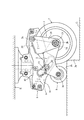
本発明に係る段差対応キャスター装置は、図1に示すように、台車や歩行補助器等の被取着部材Bに取着される保持本体1と、主車輪7が下部2bに枢着されると共に、上部2aが保持本体1の側壁部10に枢着された主車輪支持部材2と、副車輪8が前部3cに枢着されると共に後部3dが主車輪7と同軸心状に枢着された副車輪支持部材3と、主車輪7よりも前方位置かつ副車輪8よりも後方位置で副車輪支持部材3に取着されたスライドローラ30と、を備えている。
本発明に係る段差対応キャスター装置は、図1に示すように、台車や歩行補助器等の被取着部材Bに取着される保持本体1と、主車輪7が下部2bに枢着されると共に、上部2aが保持本体1の側壁部10に枢着された主車輪支持部材2と、副車輪8が前部3cに枢着されると共に後部3dが主車輪7と同軸心状に枢着された副車輪支持部材3と、主車輪7よりも前方位置かつ副車輪8よりも後方位置で副車輪支持部材3に取着されたスライドローラ30と、を備えている。
さらに、保持本体1の前部に一端部9aが取着されると共に他端部9bが副車輪支持部材3に取着された引張りコイルバネ等の弾発付勢部材9(図1乃至図6において二点鎖線で図示する)を備えている。
また、保持本体1に主車輪支持部材2を揺動自在に枢着するための左右水平状の第1枢着軸51と、主車輪支持部材2に主車輪7を回転自在及び副車輪支持部材3を揺動自在に枢着するための左右水平状の第2枢着軸(主車軸)52と、副車輪支持部材3に副車輪8を回転自在に取着するための左右水平状の枢支軸(副車軸)58と、副車輪支持部材3にスライドローラ30を回転自在取着するための左右水平状のローラ軸53と、を備えている。
また、保持本体1に主車輪支持部材2を揺動自在に枢着するための左右水平状の第1枢着軸51と、主車輪支持部材2に主車輪7を回転自在及び副車輪支持部材3を揺動自在に枢着するための左右水平状の第2枢着軸(主車軸)52と、副車輪支持部材3に副車輪8を回転自在に取着するための左右水平状の枢支軸(副車軸)58と、副車輪支持部材3にスライドローラ30を回転自在取着するための左右水平状のローラ軸53と、を備えている。
そして、主車輪7が段差端面Jaに接触していない(段差手前平坦面Gを走行している)通常走行姿勢において、主車輪支持部材2と保持本体1の枢着部(第1枢着軸51)の第1枢着軸心Laを、主車輪支持部材2と主車輪7との枢着部(第2枢着軸52)の第2枢着軸心Lbよりも後上方位置になるように配設している。そして、第1枢着軸心Laと第2枢着軸心Lbとを側面視で結んだ仮想直線(図1乃至図6に一点鎖線で示す)を揺動基準線Tと呼ぶと、通常走行姿勢において、揺動基準線Tが前方下傾状となるように構成している。
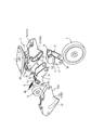
図1と図7に示すように、保持本体1は、被取着部材B(図7に於ては図示省略)に固
着されるベース部を有する取付部材19と、取付部材19に旋回用軸部材18及び軸受部材17を介して取着されるケーシング部材16と、を備え、取付部材19に対してケーシング部材16を鉛直状軸心S廻りに回転(旋回)自在に構成している。言い換えると、保持本体1は、被取着部材Bに対して、ケーシング部材16が鉛直状軸心S廻りに回転自在である。
着されるベース部を有する取付部材19と、取付部材19に旋回用軸部材18及び軸受部材17を介して取着されるケーシング部材16と、を備え、取付部材19に対してケーシング部材16を鉛直状軸心S廻りに回転(旋回)自在に構成している。言い換えると、保持本体1は、被取着部材Bに対して、ケーシング部材16が鉛直状軸心S廻りに回転自在である。
ケーシング部材16は、左右一対の側壁部10,10を有し、左右一対の側壁部10,10夫々に、スライドローラ30をガイドするための側面視前下方凸状円弧型のガイド溝13を形成している。また、ケーシング部材16は、一方の側壁部10(10A)を有する第1ケース半体16Aと、他方の側壁部10(10B)を有する第2ケース半体16Bと、を備えた半割構造である。
なお、ガイド溝13は後方下傾状であれば良く、図示省略するが直線型であっても良い。
なお、ガイド溝13は後方下傾状であれば良く、図示省略するが直線型であっても良い。
主車輪支持部材2は、第1枢着軸51(図7に於て図示省略)が挿通する貫孔を有すると共に、第2枢着軸52(図7に於ては図示省略)を両持ち梁状に支持するための貫通孔を有する左右一対の支持片部21,21を備えている。そして、主車輪支持部材2は、支持片部21,21の上部を左右方向に連結する上壁部22を有し、全体として門型に形成している。
副車輪支持部材3は、第2枢着軸52が挿通する貫通孔と、ローラ軸53(図7に於ては図示省略)が挿通する貫孔と、枢支軸58(図7に於ては図示省略)を両持ち梁状に支持するため貫通孔と、を有する左右一対の側片部31,31を備えている。そして、副車輪支持部材3は、左右一対の側片部31,31を左右方向に連結する上壁部32を有し、全体として門型に形成している。
スライドローラ30は、左右一対に設けられ、副車輪支持部材3の側片部31よりも左右外方位置に配設されて、ローラ軸53の両端部に回転自在に取着されている。
なお、図1乃至図6に於て、保持本体1の左側の側壁部10を破断した場合を図示しているため、実線で示すスライドローラ30は、図示省略の破断した側壁部10に形成されているガイド溝13に差込まれて案内される。
なお、図1乃至図6に於て、保持本体1の左側の側壁部10を破断した場合を図示しているため、実線で示すスライドローラ30は、図示省略の破断した側壁部10に形成されているガイド溝13に差込まれて案内される。
弾発付勢部材9は、上端部(一端部)9aがケーシング部材16の前部に取着され、下端部(他端部)9bが、副車輪支持部材3の左右一対の側片部31,31の左右内方位置に配設され、ローラ軸53を介して副車輪支持部材3に取着されている。つまり、弾発付勢部材9は、後方下傾状姿勢に保持され、副車輪支持部材3を前上方へ常時弾発付勢する。
副車輪支持部材3は、弾発付勢部材9によって、通常走行姿勢では、スライドローラ30がガイド溝13内の前上端部に配設されるように前上方へ弾発付勢され、上壁部32がケーシング部材16に取着したゴム等の緩衝部材5(図7に於ては図示省略)に当接して前上方への揺動が規制され、所定の待機位置に停止している。
また、副車輪支持部材3は、弾発付勢部材9によって、通常走行姿勢では、主車輪7が接地している段差手前平坦面Gから所定高さ寸法をもって副車輪8の下端が配設される。所定高さ寸法は、段差J(段差端面Jaと段差上面Jb)の高さ寸法よりも大きく設定している。
次に、本発明の段差対応キャスター装置の作用と合わせて構造を説明する。
図1に示すように、台車等の被取着部材Bが、使用者によって、前方走行させるための操作力を受けると、副車輪8が所定高さ寸法を保持したまま、主車輪7にて段差手前平坦面Gを走行する。段差Jに近づくと、副車輪8は段差端面Jaに接触することなく、段差端面Jaよりも前方へ進む。
図1に示すように、台車等の被取着部材Bが、使用者によって、前方走行させるための操作力を受けると、副車輪8が所定高さ寸法を保持したまま、主車輪7にて段差手前平坦面Gを走行する。段差Jに近づくと、副車輪8は段差端面Jaに接触することなく、段差端面Jaよりも前方へ進む。
図2に示すように、主車輪7が段差端面Jaに接触すると、被取着部材B及び保持本体
1は使用者からの操作力(前進付与力)によって前進するが、主車輪7は段差端面Jaによって前進が阻止される。
このように主車輪7が段差端面Jaに接触した際、保持本体1から見て(通常走行姿勢と比べて)、主車輪7は段差端面Jaによって押されて後方へ移動し、主車輪支持部材2の下部2bが第1枢着軸心La廻りに後方へ揺動する。副車輪支持部材3は、弾発付勢部材9の弾発付勢力に抗して、主車輪支持部材2と第2枢着軸52と主車輪7とによって引っ張られて、後部3dが、後方へ移動する。スライドローラ30は、ガイド溝13に案内されて、後方かつ下方へ移動する。スライドローラ30の後下方への円弧状移動によって、副車輪支持部材3の前部3cが、後方かつ下方へ揺動(移動)して、副車輪8を段差上面Jbに押圧する。
1は使用者からの操作力(前進付与力)によって前進するが、主車輪7は段差端面Jaによって前進が阻止される。
このように主車輪7が段差端面Jaに接触した際、保持本体1から見て(通常走行姿勢と比べて)、主車輪7は段差端面Jaによって押されて後方へ移動し、主車輪支持部材2の下部2bが第1枢着軸心La廻りに後方へ揺動する。副車輪支持部材3は、弾発付勢部材9の弾発付勢力に抗して、主車輪支持部材2と第2枢着軸52と主車輪7とによって引っ張られて、後部3dが、後方へ移動する。スライドローラ30は、ガイド溝13に案内されて、後方かつ下方へ移動する。スライドローラ30の後下方への円弧状移動によって、副車輪支持部材3の前部3cが、後方かつ下方へ揺動(移動)して、副車輪8を段差上面Jbに押圧する。
そして、使用者からの前進付与力によって、被取着部材B及び保持本体1が、さらに前進すると、図3、図4、図5と順次示すように、保持本体1から見て(通常走行姿勢と比べて)、主車輪7が後方へ移動し、主車輪支持部材2の下部2bが後方へ揺動して、副車輪支持部材3は後部3dが後方へ移動し、スライドローラ30がガイド溝13によって案内されて、ガイド溝13の後下端部まで円弧状移動し、副車輪支持部材3の前部3cを、後方かつ下方へ揺動して、副車輪8を段差上面Jbに強い力で押し付けて、被取着部材Bと保持本体1と主車輪支持部材2と主車輪7を上方かつ前方へ押し上げる(浮き上がらせる)。
つまり、使用者からの前進付与力によって前進しようとする主車輪7が、段差端面Jaに接触することで発生する段差端面Jaからの反力を、副車輪8が段差上面Jbを押す力に変換し、副車輪8が段差上面Jbを押す際の反力を、被取着部材Bと保持本体1と主車輪支持部材2と主車輪7を押し上げる力に変換して、使用者が被取着部材Bを上方へ持ち上げるような力を付与しなくとも、通常走行時と同様の前進力を付与するだけで、主車輪7が段差端面Ja(段差J)を乗り超える。
さらに、図3、図4、図5と順次示すように、主車輪7が後方へ移動し、主車輪支持部材2の下部2bが後方へ揺動して、揺動基準線Tが前方下傾状姿勢から鉛直状姿勢を介して後方下傾状姿勢に切り替わる。つまり、主車輪支持部材2の上部2aが、保持本体1を前上方へ押し上げるように作用し、押し上げ効果を高めている。
そして、図6に示すように、主車輪7が段差上面Jbに接地すれば、副車輪8が段差上面Jbから離間し、弾発付勢部材9の弾発付勢力によって、副車輪8及び副車輪支持部材3は、所定の待機位置に戻るように揺動する。
この戻り揺動の際に、副車輪支持部材3の上壁部32が、ケーシング部材16に取着されている緩衝部材5に当接して上方への揺動が規制されて所定の待機位置に停止する。緩衝部材5による停止は、例えば、スライドローラ30がガイド溝13の前上端内面に当接することで停止させる場合に比べて、衝撃を緩和し、スライドローラ30やローラ軸53が損傷や変形せず故障を防止できる。
この戻り揺動の際に、副車輪支持部材3の上壁部32が、ケーシング部材16に取着されている緩衝部材5に当接して上方への揺動が規制されて所定の待機位置に停止する。緩衝部材5による停止は、例えば、スライドローラ30がガイド溝13の前上端内面に当接することで停止させる場合に比べて、衝撃を緩和し、スライドローラ30やローラ軸53が損傷や変形せず故障を防止できる。
なお、本発明は、設計変更可能であって、保持本体1は、取付部材19とケーシング部材16とを一体化とした(相互に非旋回とした)構造とし、被取着部材Bにケーシング部材16を鉛直状軸心S廻りに旋回不可能に固着するものであっても良い。つまり、本発明の段差対応キャスター装置は、旋回型キャスター装置と固定型(非旋回型)キャスター装置の何れであっても良い。ケーシング部材16は、樹脂又はダイキャスト等の金型成型品が好ましいが、板金品(プレス加工品)と樹脂成型品の組み合わせにて形成するも良い。弾発付勢部材9は、下端部9bが(ローラ軸53を介さずに)直接的に副車輪支持部材3に取着するも良い。また、被取着部材Bは、台車、歩行補助器、車椅子、ショッピングカート等、人力にて車輪走行するためのものであれば良い。
以上のように、本発明の段差対応キャスター装置は、主車輪7が段差端面Jaに接触した際に段差上面Jbに当接する副車輪8を備えた段差対応キャスター装置に於て、被取着部材Bに取着されると共に左右一対の側壁部10を有する保持本体1と、上記主車輪7が下部2bに枢着されると共に上部2aが上記保持本体1に枢着された主車輪支持部材2と、上記副車輪8が前部3cに枢着されると共に後部3dが上記主車輪7と同軸心状に上記主車輪支持部材2に枢着された副車輪支持部材3と、上記主車輪7よりも前方位置で上記副車輪支持部材3に取着されたスライドローラ30と、を備え、上記保持本体1は、上記側壁部10に上記スライドローラ30をガイドするための側面視後方下傾状のガイド溝13を有し、上記主車輪7が上記段差端面Jaに接触することで、上記主車輪支持部材2が後方へ揺動すると共に上記副車輪支持部材3が後方へ移動し、上記スライドローラ30が上記ガイド溝13に案内されて上記副車輪支持部材3の前部3cが下方へ揺動して、上記副車輪8が上記段差上面Jbに押圧されて、上記主車輪7が上記段差端面Jaを乗り越えるように構成したので、副車輪8を強い力で段差上面Jbに当接させて、台車や歩行補助器、ショッピングカート等の被取着部材Bや主車輪7を上昇させることができる。従って、使用者が大きな力で被取着部材Bを走行させたり持ち上げたりする必要がなく、小さな力で効率良く(容易に軽く)段差端面Jaを乗り越えることができる。主車輪支持部材2及び副車輪支持部材3の前後移動量を小さくしながらも副車輪8の上下移動量を大きくできるため、段差乗り越えに十分な押圧力を発揮可能でありながら、装置全体の前後寸法を短くできて、コンパクト化を図れる。平面視で、段差端面Jaに対して主車輪7が斜めに接触するような場合(平面視で段差端面Jaに主車輪7が直角状に接触しない場合)であっても、こじれ(こぜ)を生じること無く、主車輪7と副車輪8がスムーズに作動し、安定した段差乗り越え作用を得ることができる。また、このような機構は設計の自由度が高く、主車輪7の大きさ等顧客のニーズに合った段差対応キャスター装置を容易に得ることができる。
また、上記主車輪7が上記段差端面Jaに接触していない通常走行姿勢において、上記主車輪支持部材2と上記保持本体1との枢着部の第1枢着軸心Laを、上記主車輪支持部材2と上記主車輪7との枢着部の第2枢着軸心Lbよりも後上方位置になるように配設して、上記第1枢着軸心Laと上記第2枢着軸心Lbとを側面視で結んだ揺動基準線Tが前方下傾状姿勢になるように構成し、上記主車輪7が上記段差端面Jaに接触して乗り越える際に、上記揺動基準線Tが前方下傾状姿勢から鉛直状姿勢を介して後方下傾状姿勢に切り替わるように構成したので、副車輪8による被取着部材Bや保持本体1の押し上げ(浮き上がり)作用を補助する(増幅させる)ことができ、軽く容易に段差端面Jaを乗り越えることができる。
また、上記主車輪支持部材2は、上記主車輪7が枢着される左右一対の支持片部21,21と、該左右一対の支持片部21,21の上部を連結する上壁部22と、を有する門型であるので、大きな外力(段差端面Jaとの衝突力)が作用する主車輪7及び主車軸(第2枢着軸)52を、両持ち梁状に強く保持した状態で揺動自在にでき、段差端面Jaに主車輪7が接触した際の後方揺動作動時に、スムーズかつ安定して段差乗り越え効果を発揮できる。特に、平面視で、段差端面Jaに対して主車輪7が斜めに接触するような場合(平面視で段差端面Jaに主車輪7が直角状に接触しない場合)に、主車輪7や主車軸(第2枢着軸)52が、こじれ(こぜ)を生じること無く、確実かつスムーズに後方揺動できる。
また、上記ガイド溝13は、側面視前下方凸状円弧型に形成されているので、スライドローラ30の左右移動量が僅かであっても、上下移動量を大きく得ることができ、保持本体1(ケーシング部材16)の前後寸法をコンパクトにできる。また、強い力で段差上面Jbを押圧できるため、その反力が十分に強く、被取着部材Bを強い力で押し上げることが可能となる。主車輪7の後方揺動に伴って、副車輪支持部材3の前部3cが、こじれ(こぜ)を生じること無く、スムーズかつ安定して揺動できて、確実に段差乗り越え効果を発揮できる。
1 保持本体
2 主車輪支持部材
2a 上部
2b 下部
3 副車輪支持部材
3c 前部
3d 後部
7 主車輪
8 副車輪
10 側壁部
13 ガイド溝
21 支持片部
22 上壁部
30 スライドローラ
B 被取着部材
Ja 段差端面
Jb 段差上面
La 第1枢着軸心
Lb 第2枢着軸心
T 揺動基準線
2 主車輪支持部材
2a 上部
2b 下部
3 副車輪支持部材
3c 前部
3d 後部
7 主車輪
8 副車輪
10 側壁部
13 ガイド溝
21 支持片部
22 上壁部
30 スライドローラ
B 被取着部材
Ja 段差端面
Jb 段差上面
La 第1枢着軸心
Lb 第2枢着軸心
T 揺動基準線
Claims (4)
- 主車輪(7)が段差端面(Ja)に接触した際に段差上面(Jb)に当接する副車輪(8)を備えた段差対応キャスター装置に於て、
被取着部材(B)に取着されると共に左右一対の側壁部(10)を有する保持本体(1)と、上記主車輪(7)が下部(2b)に枢着されると共に上部(2a)が上記保持本体(1)に枢着された主車輪支持部材(2)と、上記副車輪(8)が前部(3c)に枢着されると共に後部(3d)が上記主車輪(7)と同軸心状に上記主車輪支持部材(2)に枢着された副車輪支持部材(3)と、上記主車輪(7)よりも前方位置で上記副車輪支持部材(3)に取着されたスライドローラ(30)と、を備え、
上記保持本体(1)は、上記側壁部(10)に上記スライドローラ(30)をガイドするための側面視後方下傾状のガイド溝(13)を有し、
上記主車輪(7)が上記段差端面(Ja)に接触することで、上記主車輪支持部材(2)が後方へ揺動すると共に上記副車輪支持部材(3)が後方へ移動し、上記スライドローラ(30)が上記ガイド溝(13)に案内されて上記副車輪支持部材(3)の前部(3c)が下方へ揺動して、上記副車輪(8)が上記段差上面(Jb)に押圧されて、上記主車輪(7)が上記段差端面(Ja)を乗り越えるように構成したことを特徴とする段差対応キャスター装置。 - 上記主車輪(7)が上記段差端面(Ja)に接触していない通常走行姿勢において、上記主車輪支持部材(2)と上記保持本体(1)との枢着部の第1枢着軸心(La)を、上記主車輪支持部材(2)と上記主車輪(7)との枢着部の第2枢着軸心(Lb)よりも後上方位置になるように配設して、上記第1枢着軸心(La)と上記第2枢着軸心(Lb)とを側面視で結んだ揺動基準線(T)が前方下傾状姿勢になるように構成し、
上記主車輪(7)が上記段差端面(Ja)に接触して乗り越える際に、上記揺動基準線(T)が前方下傾状姿勢から鉛直状姿勢を介して後方下傾状姿勢に切り替わるように構成した請求項1記載の段差対応キャスター装置。 - 上記主車輪支持部材(2)は、上記主車輪(7)が枢着される左右一対の支持片部(21)(21)と、該左右一対の支持片部(21)(21)の上部を連結する上壁部(22)と、を有する門型である請求項1又は2記載の段差対応キャスター装置。
- 上記ガイド溝(13)は、側面視前下方凸状円弧型に形成されている請求項1,2又は3記載の段差対応キャスター装置。
Priority Applications (2)
| Application Number | Priority Date | Filing Date | Title |
|---|---|---|---|
| US16/650,251 US11155120B2 (en) | 2017-12-07 | 2018-06-20 | Stage-corresponding caster device |
| EP18886128.0A EP3722105B1 (en) | 2017-12-07 | 2018-06-20 | Step adaptive caster device |
Applications Claiming Priority (2)
| Application Number | Priority Date | Filing Date | Title |
|---|---|---|---|
| JP2017-234796 | 2017-12-07 | ||
| JP2017234796A JP6607909B2 (ja) | 2017-12-07 | 2017-12-07 | 段差対応キャスター装置 |
Publications (1)
| Publication Number | Publication Date |
|---|---|
| WO2019111432A1 true WO2019111432A1 (ja) | 2019-06-13 |
Family
ID=66751005
Family Applications (1)
| Application Number | Title | Priority Date | Filing Date |
|---|---|---|---|
| PCT/JP2018/023482 Ceased WO2019111432A1 (ja) | 2017-12-07 | 2018-06-20 | 段差対応キャスター装置 |
Country Status (4)
| Country | Link |
|---|---|
| US (1) | US11155120B2 (ja) |
| EP (1) | EP3722105B1 (ja) |
| JP (1) | JP6607909B2 (ja) |
| WO (1) | WO2019111432A1 (ja) |
Families Citing this family (6)
| Publication number | Priority date | Publication date | Assignee | Title |
|---|---|---|---|---|
| US11536039B2 (en) * | 2017-12-08 | 2022-12-27 | Seaway Painting, L.L.C. | Tower apparatus |
| CZ2020330A3 (cs) * | 2020-06-10 | 2021-04-07 | BORCAD Medical a.s. | Mechanismus polohovatelného manipulačního kolečka a způsob jeho polohování |
| JP7603980B2 (ja) * | 2021-04-06 | 2024-12-23 | 学校法人 東洋大学 | 移動体用車輪装置 |
| CN116767392B (zh) * | 2022-03-11 | 2026-03-13 | 美的集团(上海)有限公司 | 底盘及机器人 |
| JP7828638B2 (ja) * | 2022-03-28 | 2026-03-12 | 大森工業株式会社 | 車輪構造体 |
| WO2025029967A2 (en) * | 2023-07-31 | 2025-02-06 | Karsten Manufacturing Corporation | Multi-wheel casters |
Citations (2)
| Publication number | Priority date | Publication date | Assignee | Title |
|---|---|---|---|---|
| JPH0556502U (ja) * | 1991-12-26 | 1993-07-27 | 俊 大塚 | キャスタ |
| JP2016203654A (ja) | 2015-04-15 | 2016-12-08 | 株式会社ユーエイキャスター | 段差対応型のキャスター装置 |
Family Cites Families (13)
| Publication number | Priority date | Publication date | Assignee | Title |
|---|---|---|---|---|
| US2123707A (en) * | 1937-06-26 | 1938-07-12 | Bloch Arthur | Wheel device |
| DE3175653D1 (en) * | 1980-11-10 | 1987-01-15 | Wheel Dev Ltd | Spring member |
| JP3046565B2 (ja) * | 1997-06-13 | 2000-05-29 | 邦夫 隈本 | 段差越え用車輪 |
| JP3528768B2 (ja) * | 2000-07-31 | 2004-05-24 | 有限会社 福富ヘルスサイエンスアンドサービス | 車椅子における前車輪用補助具 |
| US6454065B1 (en) * | 2001-07-06 | 2002-09-24 | Chieh-Chiung Chen | Wheel rack improvement of a trolley suitcase |
| JP2004042685A (ja) * | 2002-07-08 | 2004-02-12 | Youth Engineering Co Ltd | キャスター |
| AT412777B (de) * | 2003-03-04 | 2005-07-25 | Bierma Jochum | Treppengängiger handwagen |
| US20060267295A1 (en) * | 2004-03-09 | 2006-11-30 | Gensou You | Supporting structure for wheel |
| JP2006131198A (ja) * | 2004-10-04 | 2006-05-25 | Kazuyoshi Kazaoka | 車輪構造体及び車輪構造体を有する車輌 |
| CH698063B1 (de) * | 2005-03-31 | 2009-05-15 | Degonda Rehab Sa | Lenkradeinheit und Rollstuhl mit mindestens einer Lenkradeinheit. |
| JP4059347B2 (ja) * | 2005-04-28 | 2008-03-12 | 象印ベビー株式会社 | キャスター |
| JP4670773B2 (ja) * | 2006-08-30 | 2011-04-13 | トヨタ自動車株式会社 | 平行二輪車 |
| US8650710B1 (en) * | 2012-12-15 | 2014-02-18 | Herbert A. Waggener | Caster wheel lift and brake assembly |
-
2017
- 2017-12-07 JP JP2017234796A patent/JP6607909B2/ja active Active
-
2018
- 2018-06-20 EP EP18886128.0A patent/EP3722105B1/en active Active
- 2018-06-20 US US16/650,251 patent/US11155120B2/en active Active
- 2018-06-20 WO PCT/JP2018/023482 patent/WO2019111432A1/ja not_active Ceased
Patent Citations (2)
| Publication number | Priority date | Publication date | Assignee | Title |
|---|---|---|---|---|
| JPH0556502U (ja) * | 1991-12-26 | 1993-07-27 | 俊 大塚 | キャスタ |
| JP2016203654A (ja) | 2015-04-15 | 2016-12-08 | 株式会社ユーエイキャスター | 段差対応型のキャスター装置 |
Non-Patent Citations (1)
| Title |
|---|
| See also references of EP3722105A4 |
Also Published As
| Publication number | Publication date |
|---|---|
| JP6607909B2 (ja) | 2019-11-20 |
| EP3722105C0 (en) | 2025-08-06 |
| US20210213778A1 (en) | 2021-07-15 |
| EP3722105A1 (en) | 2020-10-14 |
| EP3722105A4 (en) | 2021-11-10 |
| JP2019099066A (ja) | 2019-06-24 |
| US11155120B2 (en) | 2021-10-26 |
| EP3722105B1 (en) | 2025-08-06 |
Similar Documents
| Publication | Publication Date | Title |
|---|---|---|
| WO2019111432A1 (ja) | 段差対応キャスター装置 | |
| JP3190006U (ja) | ブレーキ機能を備えたホイールセット | |
| US11083304B2 (en) | Electric bed | |
| US10207731B2 (en) | Expandable child carrier | |
| KR20030057352A (ko) | 유모차 | |
| JPWO2013038786A1 (ja) | 車両用ターンシグナルスイッチ装置 | |
| CN106687356A (zh) | 婴儿车 | |
| JP2020075707A (ja) | 手押し車及び障害物乗越機構 | |
| JP3814195B2 (ja) | 運搬台車の制動装置 | |
| US5480177A (en) | Chair | |
| JP5866630B2 (ja) | シートクッション跳ね上げ式の車両用シート | |
| JP2010111160A (ja) | キャスター | |
| JP2015013600A (ja) | 乳母車 | |
| JP5232597B2 (ja) | テーブル | |
| JP4738881B2 (ja) | 育児器具 | |
| JP2005199779A (ja) | キャスタ | |
| JP2556788Y2 (ja) | キャスタ | |
| JP2007283082A (ja) | 車椅子用ブレーキ装置及びブレーキ装置付き車椅子 | |
| CN223821517U (zh) | 安全座椅 | |
| JP6071727B2 (ja) | シーソースイッチ装置 | |
| JP6746460B2 (ja) | 入浴用車椅子 | |
| JPH081121Y2 (ja) | ベビーカーのキャスター機構 | |
| JP3100118B2 (ja) | キャスタ | |
| JP2000197536A (ja) | ロビ―チェアにおけるフットレスト装置 | |
| JP4121105B2 (ja) | 履帯式作業車両の遊動輪装置のマウント構造 |
Legal Events
| Date | Code | Title | Description |
|---|---|---|---|
| 121 | Ep: the epo has been informed by wipo that ep was designated in this application |
Ref document number: 18886128 Country of ref document: EP Kind code of ref document: A1 |
|
| NENP | Non-entry into the national phase |
Ref country code: DE |
|
| ENP | Entry into the national phase |
Ref document number: 2018886128 Country of ref document: EP Effective date: 20200707 |
|
| WWG | Wipo information: grant in national office |
Ref document number: 2018886128 Country of ref document: EP |