WO2019116145A1 - Dispositif de commande de charge et dispositif électronique ayant une batterie secondaire - Google Patents
Dispositif de commande de charge et dispositif électronique ayant une batterie secondaire Download PDFInfo
- Publication number
- WO2019116145A1 WO2019116145A1 PCT/IB2018/059485 IB2018059485W WO2019116145A1 WO 2019116145 A1 WO2019116145 A1 WO 2019116145A1 IB 2018059485 W IB2018059485 W IB 2018059485W WO 2019116145 A1 WO2019116145 A1 WO 2019116145A1
- Authority
- WO
- WIPO (PCT)
- Prior art keywords
- secondary battery
- battery
- secondary batteries
- neural network
- abnormality
- Prior art date
- Legal status (The legal status is an assumption and is not a legal conclusion. Google has not performed a legal analysis and makes no representation as to the accuracy of the status listed.)
- Ceased
Links
Images





Classifications
-
- H—ELECTRICITY
- H01—ELECTRIC ELEMENTS
- H01M—PROCESSES OR MEANS, e.g. BATTERIES, FOR THE DIRECT CONVERSION OF CHEMICAL ENERGY INTO ELECTRICAL ENERGY
- H01M10/00—Secondary cells; Manufacture thereof
- H01M10/42—Methods or arrangements for servicing or maintenance of secondary cells or secondary half-cells
- H01M10/4235—Safety or regulating additives or arrangements in electrodes, separators or electrolyte
-
- B—PERFORMING OPERATIONS; TRANSPORTING
- B60—VEHICLES IN GENERAL
- B60L—PROPULSION OF ELECTRICALLY-PROPELLED VEHICLES; SUPPLYING ELECTRIC POWER FOR AUXILIARY EQUIPMENT OF ELECTRICALLY-PROPELLED VEHICLES; ELECTRODYNAMIC BRAKE SYSTEMS FOR VEHICLES IN GENERAL; MAGNETIC SUSPENSION OR LEVITATION FOR VEHICLES; MONITORING OPERATING VARIABLES OF ELECTRICALLY-PROPELLED VEHICLES; ELECTRIC SAFETY DEVICES FOR ELECTRICALLY-PROPELLED VEHICLES
- B60L3/00—Electric devices on electrically-propelled vehicles for safety purposes; Monitoring operating variables, e.g. speed, deceleration or energy consumption
- B60L3/0023—Detecting, eliminating, remedying or compensating for drive train abnormalities, e.g. failures within the drive train
- B60L3/0046—Detecting, eliminating, remedying or compensating for drive train abnormalities, e.g. failures within the drive train relating to electric energy storage systems, e.g. batteries or capacitors
-
- B—PERFORMING OPERATIONS; TRANSPORTING
- B60—VEHICLES IN GENERAL
- B60L—PROPULSION OF ELECTRICALLY-PROPELLED VEHICLES; SUPPLYING ELECTRIC POWER FOR AUXILIARY EQUIPMENT OF ELECTRICALLY-PROPELLED VEHICLES; ELECTRODYNAMIC BRAKE SYSTEMS FOR VEHICLES IN GENERAL; MAGNETIC SUSPENSION OR LEVITATION FOR VEHICLES; MONITORING OPERATING VARIABLES OF ELECTRICALLY-PROPELLED VEHICLES; ELECTRIC SAFETY DEVICES FOR ELECTRICALLY-PROPELLED VEHICLES
- B60L58/00—Methods or circuit arrangements for monitoring or controlling batteries or fuel cells, specially adapted for electric vehicles
- B60L58/10—Methods or circuit arrangements for monitoring or controlling batteries or fuel cells, specially adapted for electric vehicles for monitoring or controlling batteries
- B60L58/16—Methods or circuit arrangements for monitoring or controlling batteries or fuel cells, specially adapted for electric vehicles for monitoring or controlling batteries responding to battery ageing, e.g. to the number of charging cycles or the state of health [SoH]
-
- B—PERFORMING OPERATIONS; TRANSPORTING
- B60—VEHICLES IN GENERAL
- B60L—PROPULSION OF ELECTRICALLY-PROPELLED VEHICLES; SUPPLYING ELECTRIC POWER FOR AUXILIARY EQUIPMENT OF ELECTRICALLY-PROPELLED VEHICLES; ELECTRODYNAMIC BRAKE SYSTEMS FOR VEHICLES IN GENERAL; MAGNETIC SUSPENSION OR LEVITATION FOR VEHICLES; MONITORING OPERATING VARIABLES OF ELECTRICALLY-PROPELLED VEHICLES; ELECTRIC SAFETY DEVICES FOR ELECTRICALLY-PROPELLED VEHICLES
- B60L58/00—Methods or circuit arrangements for monitoring or controlling batteries or fuel cells, specially adapted for electric vehicles
- B60L58/10—Methods or circuit arrangements for monitoring or controlling batteries or fuel cells, specially adapted for electric vehicles for monitoring or controlling batteries
- B60L58/18—Methods or circuit arrangements for monitoring or controlling batteries or fuel cells, specially adapted for electric vehicles for monitoring or controlling batteries of two or more battery modules
-
- B—PERFORMING OPERATIONS; TRANSPORTING
- B60—VEHICLES IN GENERAL
- B60L—PROPULSION OF ELECTRICALLY-PROPELLED VEHICLES; SUPPLYING ELECTRIC POWER FOR AUXILIARY EQUIPMENT OF ELECTRICALLY-PROPELLED VEHICLES; ELECTRODYNAMIC BRAKE SYSTEMS FOR VEHICLES IN GENERAL; MAGNETIC SUSPENSION OR LEVITATION FOR VEHICLES; MONITORING OPERATING VARIABLES OF ELECTRICALLY-PROPELLED VEHICLES; ELECTRIC SAFETY DEVICES FOR ELECTRICALLY-PROPELLED VEHICLES
- B60L58/00—Methods or circuit arrangements for monitoring or controlling batteries or fuel cells, specially adapted for electric vehicles
- B60L58/10—Methods or circuit arrangements for monitoring or controlling batteries or fuel cells, specially adapted for electric vehicles for monitoring or controlling batteries
- B60L58/18—Methods or circuit arrangements for monitoring or controlling batteries or fuel cells, specially adapted for electric vehicles for monitoring or controlling batteries of two or more battery modules
- B60L58/21—Methods or circuit arrangements for monitoring or controlling batteries or fuel cells, specially adapted for electric vehicles for monitoring or controlling batteries of two or more battery modules having the same nominal voltage
-
- G—PHYSICS
- G01—MEASURING; TESTING
- G01R—MEASURING ELECTRIC VARIABLES; MEASURING MAGNETIC VARIABLES
- G01R31/00—Arrangements for testing electric properties; Arrangements for locating electric faults; Arrangements for electrical testing characterised by what is being tested not provided for elsewhere
- G01R31/36—Arrangements for testing, measuring or monitoring the electrical condition of accumulators or electric batteries, e.g. capacity or state of charge [SoC]
- G01R31/367—Software therefor, e.g. for battery testing using modelling or look-up tables
-
- H—ELECTRICITY
- H01—ELECTRIC ELEMENTS
- H01M—PROCESSES OR MEANS, e.g. BATTERIES, FOR THE DIRECT CONVERSION OF CHEMICAL ENERGY INTO ELECTRICAL ENERGY
- H01M10/00—Secondary cells; Manufacture thereof
- H01M10/42—Methods or arrangements for servicing or maintenance of secondary cells or secondary half-cells
- H01M10/425—Structural combination with electronic components, e.g. electronic circuits integrated to the outside of the casing
- H01M10/4257—Smart batteries, e.g. electronic circuits inside the housing of the cells or batteries
-
- H—ELECTRICITY
- H01—ELECTRIC ELEMENTS
- H01M—PROCESSES OR MEANS, e.g. BATTERIES, FOR THE DIRECT CONVERSION OF CHEMICAL ENERGY INTO ELECTRICAL ENERGY
- H01M10/00—Secondary cells; Manufacture thereof
- H01M10/42—Methods or arrangements for servicing or maintenance of secondary cells or secondary half-cells
- H01M10/48—Accumulators combined with arrangements for measuring, testing or indicating the condition of cells, e.g. the level or density of the electrolyte
-
- H—ELECTRICITY
- H01—ELECTRIC ELEMENTS
- H01M—PROCESSES OR MEANS, e.g. BATTERIES, FOR THE DIRECT CONVERSION OF CHEMICAL ENERGY INTO ELECTRICAL ENERGY
- H01M10/00—Secondary cells; Manufacture thereof
- H01M10/42—Methods or arrangements for servicing or maintenance of secondary cells or secondary half-cells
- H01M10/48—Accumulators combined with arrangements for measuring, testing or indicating the condition of cells, e.g. the level or density of the electrolyte
- H01M10/482—Accumulators combined with arrangements for measuring, testing or indicating the condition of cells, e.g. the level or density of the electrolyte for several batteries or cells simultaneously or sequentially
-
- H—ELECTRICITY
- H02—GENERATION; CONVERSION OR DISTRIBUTION OF ELECTRIC POWER
- H02J—ELECTRIC POWER NETWORKS; CIRCUIT ARRANGEMENTS OR SYSTEMS FOR SUPPLYING OR DISTRIBUTING ELECTRIC POWER; SYSTEMS FOR STORING ELECTRIC ENERGY
- H02J7/00—Circuit arrangements for charging or discharging batteries or for supplying loads from batteries
-
- B—PERFORMING OPERATIONS; TRANSPORTING
- B60—VEHICLES IN GENERAL
- B60L—PROPULSION OF ELECTRICALLY-PROPELLED VEHICLES; SUPPLYING ELECTRIC POWER FOR AUXILIARY EQUIPMENT OF ELECTRICALLY-PROPELLED VEHICLES; ELECTRODYNAMIC BRAKE SYSTEMS FOR VEHICLES IN GENERAL; MAGNETIC SUSPENSION OR LEVITATION FOR VEHICLES; MONITORING OPERATING VARIABLES OF ELECTRICALLY-PROPELLED VEHICLES; ELECTRIC SAFETY DEVICES FOR ELECTRICALLY-PROPELLED VEHICLES
- B60L2260/00—Operating Modes
- B60L2260/40—Control modes
- B60L2260/46—Control modes by self learning
-
- B—PERFORMING OPERATIONS; TRANSPORTING
- B60—VEHICLES IN GENERAL
- B60L—PROPULSION OF ELECTRICALLY-PROPELLED VEHICLES; SUPPLYING ELECTRIC POWER FOR AUXILIARY EQUIPMENT OF ELECTRICALLY-PROPELLED VEHICLES; ELECTRODYNAMIC BRAKE SYSTEMS FOR VEHICLES IN GENERAL; MAGNETIC SUSPENSION OR LEVITATION FOR VEHICLES; MONITORING OPERATING VARIABLES OF ELECTRICALLY-PROPELLED VEHICLES; ELECTRIC SAFETY DEVICES FOR ELECTRICALLY-PROPELLED VEHICLES
- B60L2260/00—Operating Modes
- B60L2260/40—Control modes
- B60L2260/50—Control modes by future state prediction
-
- H—ELECTRICITY
- H01—ELECTRIC ELEMENTS
- H01M—PROCESSES OR MEANS, e.g. BATTERIES, FOR THE DIRECT CONVERSION OF CHEMICAL ENERGY INTO ELECTRICAL ENERGY
- H01M10/00—Secondary cells; Manufacture thereof
- H01M10/42—Methods or arrangements for servicing or maintenance of secondary cells or secondary half-cells
- H01M10/425—Structural combination with electronic components, e.g. electronic circuits integrated to the outside of the casing
- H01M2010/4271—Battery management systems including electronic circuits, e.g. control of current or voltage to keep battery in healthy state, cell balancing
-
- H—ELECTRICITY
- H01—ELECTRIC ELEMENTS
- H01M—PROCESSES OR MEANS, e.g. BATTERIES, FOR THE DIRECT CONVERSION OF CHEMICAL ENERGY INTO ELECTRICAL ENERGY
- H01M2220/00—Batteries for particular applications
- H01M2220/20—Batteries in motive systems, e.g. vehicle, ship, plane
-
- Y—GENERAL TAGGING OF NEW TECHNOLOGICAL DEVELOPMENTS; GENERAL TAGGING OF CROSS-SECTIONAL TECHNOLOGIES SPANNING OVER SEVERAL SECTIONS OF THE IPC; TECHNICAL SUBJECTS COVERED BY FORMER USPC CROSS-REFERENCE ART COLLECTIONS [XRACs] AND DIGESTS
- Y02—TECHNOLOGIES OR APPLICATIONS FOR MITIGATION OR ADAPTATION AGAINST CLIMATE CHANGE
- Y02E—REDUCTION OF GREENHOUSE GAS [GHG] EMISSIONS, RELATED TO ENERGY GENERATION, TRANSMISSION OR DISTRIBUTION
- Y02E60/00—Enabling technologies; Technologies with a potential or indirect contribution to GHG emissions mitigation
- Y02E60/10—Energy storage using batteries
-
- Y—GENERAL TAGGING OF NEW TECHNOLOGICAL DEVELOPMENTS; GENERAL TAGGING OF CROSS-SECTIONAL TECHNOLOGIES SPANNING OVER SEVERAL SECTIONS OF THE IPC; TECHNICAL SUBJECTS COVERED BY FORMER USPC CROSS-REFERENCE ART COLLECTIONS [XRACs] AND DIGESTS
- Y02—TECHNOLOGIES OR APPLICATIONS FOR MITIGATION OR ADAPTATION AGAINST CLIMATE CHANGE
- Y02T—CLIMATE CHANGE MITIGATION TECHNOLOGIES RELATED TO TRANSPORTATION
- Y02T10/00—Road transport of goods or passengers
- Y02T10/60—Other road transportation technologies with climate change mitigation effect
- Y02T10/70—Energy storage systems for electromobility, e.g. batteries
-
- Y—GENERAL TAGGING OF NEW TECHNOLOGICAL DEVELOPMENTS; GENERAL TAGGING OF CROSS-SECTIONAL TECHNOLOGIES SPANNING OVER SEVERAL SECTIONS OF THE IPC; TECHNICAL SUBJECTS COVERED BY FORMER USPC CROSS-REFERENCE ART COLLECTIONS [XRACs] AND DIGESTS
- Y02—TECHNOLOGIES OR APPLICATIONS FOR MITIGATION OR ADAPTATION AGAINST CLIMATE CHANGE
- Y02T—CLIMATE CHANGE MITIGATION TECHNOLOGIES RELATED TO TRANSPORTATION
- Y02T10/00—Road transport of goods or passengers
- Y02T10/60—Other road transportation technologies with climate change mitigation effect
- Y02T10/7072—Electromobility specific charging systems or methods for batteries, ultracapacitors, supercapacitors or double-layer capacitors
-
- Y—GENERAL TAGGING OF NEW TECHNOLOGICAL DEVELOPMENTS; GENERAL TAGGING OF CROSS-SECTIONAL TECHNOLOGIES SPANNING OVER SEVERAL SECTIONS OF THE IPC; TECHNICAL SUBJECTS COVERED BY FORMER USPC CROSS-REFERENCE ART COLLECTIONS [XRACs] AND DIGESTS
- Y02—TECHNOLOGIES OR APPLICATIONS FOR MITIGATION OR ADAPTATION AGAINST CLIMATE CHANGE
- Y02T—CLIMATE CHANGE MITIGATION TECHNOLOGIES RELATED TO TRANSPORTATION
- Y02T90/00—Enabling technologies or technologies with a potential or indirect contribution to GHG emissions mitigation
- Y02T90/10—Technologies relating to charging of electric vehicles
- Y02T90/14—Plug-in electric vehicles
Definitions
- One aspect of the present invention relates to an object, a method, or a method of manufacturing.
- the present invention relates to a process, a machine, a manufacture, or a composition (composition of matter).
- One embodiment of the present invention relates to a method for manufacturing a semiconductor device, a display device, a light-emitting device, a power storage device, a lighting device, or an electronic device.
- the present invention relates to an electronic device having a charging system and a secondary battery.
- a power storage device refers to all elements and devices having a power storage function.
- a storage battery also referred to as a secondary battery
- a lithium ion secondary battery such as a lithium ion secondary battery, a lithium ion capacitor, an all solid battery, an electric double layer capacitor, and the like are included.
- lithium ion secondary batteries having high output and high energy density can be used in portable information terminals such as mobile phones, smartphones, tablets, or notebook computers, portable music players, digital cameras, medical devices, or hybrid vehicles (HEVs).
- portable information terminals such as mobile phones, smartphones, tablets, or notebook computers, portable music players, digital cameras, medical devices, or hybrid vehicles (HEVs).
- HEVs hybrid vehicles
- demand is rapidly expanding with the development of the semiconductor industry, such as next-generation clean energy vehicles such as electric vehicles (EVs) and plug-in hybrid vehicles (PHEVs), and modern information as a source of rechargeable energy Has become an integral part of the
- a battery pack refers to one in which a battery module composed of a plurality of secondary batteries is housed together with a predetermined circuit in a container (metal can, film outer package) in order to facilitate handling of the secondary battery. .
- the battery pack has an ECU (Electronic Control Unit) to manage the operation state.
- ECU Electronic Control Unit
- the electric vehicle is a vehicle having only an electric motor as a drive unit
- a hybrid vehicle provided with both an internal combustion engine such as an engine and an electric motor.
- a plurality of secondary batteries used in automobiles are also used as one battery pack, and a plurality of sets of battery packs are disposed at the bottom of the automobile.
- secondary batteries used for electric vehicles and hybrid vehicles are deteriorated due to the number of times of charge, depth of discharge, charge current, environment (temperature change) to be charged, and the like.
- the temperature at the time of charge, the frequency of rapid charge, the charge amount by the regenerative brake, the charge timing by the regenerative brake, etc. may also be related to the deterioration.
- Patent Document 1 shows an example in which a neural network is used to calculate the remaining capacity of a storage battery.
- An object of one embodiment of the present invention is to provide a highly safe power storage system.
- an object of one embodiment of the present invention is to provide a vehicle equipped with a power storage system having excellent characteristics.
- an object of one embodiment of the present invention is to provide an electronic device in which a power storage system having excellent characteristics is mounted.
- n (n is an integer of 3 or more) secondary batteries are used in a vehicle such as an electric car
- each condition of the individual secondary batteries is monitored by the abnormality detection unit to detect an abnormality such as a micro short circuit.
- a circuit configuration is used which electrically isolates only the secondary battery having the detected abnormality from the charging system or the discharging system.
- micro short refers to a minute short inside the secondary battery, not to the extent that the positive electrode and the negative pole of the secondary battery are shorted to cause a state in which charging and discharging are not possible. It indicates a phenomenon in which a short circuit current flows slightly.
- One of the causes of micro-shorting is that charge and discharge are performed multiple times, and uneven distribution of the positive electrode active material causes local concentration of current at a part of the positive electrode and a part of the negative electrode. It is said that micro short circuit is caused due to generation of a part where one part fails or generation of a side reaction product by side reaction.
- a neural network is also called an artificial neural network and is one of machine learning techniques.
- the configuration disclosed in this specification includes a first secondary battery connected in series, a second secondary battery, a third secondary battery, and one terminal of the first secondary battery connected to the second secondary battery. And at least one switch for interrupting power supply to one terminal of the secondary battery, wherein one terminal of the first secondary battery is a wire and a switch bypassing one terminal of the second secondary battery.
- the charge control device is connected in series with the third secondary battery by switching the switch and the second secondary battery is not charged.
- a second switch is further provided between the other terminal of the second secondary battery and one terminal of the third secondary battery, and one terminal of the first secondary battery is The third secondary battery is not charged by switching the wiring and the second switch that bypass one terminal of the third secondary battery.
- the switch is an element (such as a power MOSFET) that controls on / off by an electrical signal, and is different from a switch that switches with a physical lever or a service plug.
- the switch switching can be determined by at least one microcomputer, and abnormality monitoring of n secondary batteries is sequentially performed, and an abnormal secondary battery or a secondary battery detected as having an abnormality is detected. Select and instruct each switch to bypass those secondary batteries.
- an abnormality monitoring unit including a microcomputer that monitors abnormality of the secondary battery including a micro short between the positive electrode and the negative electrode of the secondary battery and switching of the switch.
- the abnormality monitoring unit analyzes the state of the storage battery, for example, by measuring parameters such as voltage and current in the process of charging and discharging the storage battery. More specifically, for example, a charge curve or a discharge curve is analyzed.
- the charging curve refers to, for example, the transition of voltage with time or the transition of capacity with time in the charging process.
- the discharge curve means, for example, the transition of voltage with time or the transition of capacity with time in the discharge process.
- the secondary battery whose abnormality is detected is switched off and only the secondary battery is put out of service.
- a circuit (bypass circuit) bypassing the one secondary battery by turning off the switch Also called).
- Control of on / off switching of the switch is based on an electrical signal formed from control means, specifically a microcomputer or the like.
- the abnormality monitoring unit is configured to supply power from a low voltage system power supply.
- the microcomputer can also perform inference by a neural network.
- a neural network refers to a whole model that imitates a neural network of an organism, determines the connection strength between neurons by learning, and has a problem solving ability.
- a neural network has an input layer, an intermediate layer (also called a hidden layer), and an output layer.
- a neuron-to-neuron coupling strength also referred to as a weighting factor
- learning when describing a neural network, to determine a neuron-to-neuron coupling strength (also referred to as a weighting factor) from existing information may be referred to as “learning”.
- LSTM Long Short-Term Memory
- the LSTM stores the state by having the hidden layer in the RNN have memory cells, and can perform analysis, such as guessing, for a longer time.
- MAC product-sum operation
- Add adder
- a sigmoid function tanh
- Hadamard product etc.
- the software programs for executing the inference program are Python, Go, Perl, Ruby, Prolog, Visual Basic, C, C ++, Swift, Java (registered trademark),. It can be written in various programming languages such as NET.
- Applications may also be created using frameworks such as Chainer (available in Python), Caffe (available in Python and C ++), TensorFlow (available in C, C ++, and Python).
- frameworks such as Chainer (available in Python), Caffe (available in Python and C ++), TensorFlow (available in C, C ++, and Python).
- the algorithm of LSTM is programmed in Python and uses a CPU (Central Processor Unit) or a GPU (Graphics Processing Unit).
- a chip in which a CPU and a GPU are integrated into one may be called an APU (Accelerated Processing Unit), and this APU chip can also be used.
- an IC also called an inference chip
- An IC incorporating an AI system may be called a circuit (microprocessor) that performs neural network operations.
- the present invention is not particularly limited, and the secondary battery may be replaceable as a configuration for accommodating the battery in a battery holder or a battery box.
- the charge control device is a charge control device in which a plurality of battery holders are connected in series and a switch and an abnormality detection unit are connected to terminals of the battery holder.
- Another configuration disclosed in the present specification is one of the first secondary battery holder, the second secondary battery holder, the third secondary battery holder, and the first secondary battery holder connected in series. And at least one switch for interrupting power supply from the terminal to one of the terminals of the second secondary battery holder, wherein one terminal of the first secondary battery holder is of the second secondary battery holder.
- the charge control device is connected in series with the third secondary battery holder by switching between the wiring bypassing one of the terminals and the switch so as not to supply power to the second secondary battery holder.
- One embodiment of the present invention can provide a highly safe power storage system.
- Safety can be secured by detecting a secondary battery in which an abnormality such as a micro short occurs by a neural network and not using only the secondary battery in switching the switch. It is possible to avoid the danger of continuing to use the abnormal secondary battery and the adverse effects on other secondary batteries.
- the number of secondary batteries not used in switching of the switch can be counted due to deterioration, so the entire secondary battery (battery module You can also decide when to replace. Conventionally, it is often determined by the period of use and the number of cycles, and the entire secondary battery is replaced for safety even if it can be used still.
- one embodiment of the present invention is not limited to a vehicle, and can provide an electronic device in which a large number of secondary batteries are mounted and a power storage system having excellent characteristics is mounted.
- FIG. 1A and 1B are a block diagram and a perspective view illustrating one embodiment of the present invention.
- 7 is an example of a circuit diagram illustrating one embodiment of the present invention.
- the figure which shows the structure of a neural network The figure which shows the structure of a neural network.
- the figure which shows the structure of a neural network The figure which shows an example of the network model of LSTM, and a charging curve.
- FIG. 1 shows a block diagram of a system.
- the schematic diagram which shows the process of input data. Diagram showing the overall algorithm.
- FIG. FIG. FIG. The figure which shows the algorithm of LSTM.
- Embodiment 1 In this embodiment, an example in which the charge control device of the present invention is applied to an electric vehicle (EV) will be described with reference to FIG.
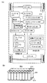
- FIG. 1A shows an example of a block diagram of an electric vehicle.
- the electric vehicle is provided with a first battery 301 as a main drive secondary battery, and a second battery 311 for supplying power to an inverter 312 for starting the motor 304.
- the abnormality monitoring unit 300 driven by the power of the second battery 311 individually selects and uses a plurality of secondary batteries that constitute the first battery 301.
- the first battery 301 mainly supplies power to the 42V system (high voltage system) in-vehicle device, and the second battery 311 supplies power to the 14V system (low voltage system) in-vehicle device.
- the second battery 311 a lead storage battery is often adopted because of cost advantages. Lead-acid batteries have larger self-discharge than lithium ion secondary batteries, and have the drawback of being easily degraded by a phenomenon called sulfation. There is a merit of making the second battery 311 a lithium ion secondary battery free of maintenance, but if it is used for a long period of time, for example, three years or more, there is a possibility that an abnormal occurrence which can not be distinguished at the time of manufacturing may occur.
- the second battery 311 for starting the inverter becomes inoperable
- the second battery 311 is a lead storage battery to prevent that the motor can not be started even if the first battery 301 has remaining capacity.
- power is supplied from the first battery 301 to the second battery 311, and charging is performed so as to always maintain a fully charged state.
- the second battery 311 may use a lead storage battery or an all solid battery.
- the lithium ion secondary battery has a positive electrode, a negative electrode, a separator, an electrolytic solution, and an outer package.
- the anode (anode) and the cathode (cathode) are replaced by charge and discharge, and the oxidation reaction and the reduction reaction are replaced, so the electrode with high reaction potential is called a positive electrode, and the reaction potential The lower electrode is called the negative electrode. Therefore, in the present specification, the positive electrode is “positive electrode” or “positive electrode” even during charging, discharging, reverse pulse current flow, or charging current flow.
- the positive electrode (positive electrode) is referred to, and the negative electrode is referred to as a "negative electrode” or "-electrode (minus electrode)".
- anode anode
- cathode cathode
- the charge and discharge may be reversed, which may cause confusion.
- anode anode
- cathode cathode
- the terms anode (anode) and cathode (cathode) are not used herein. If the terms anode (anode) and cathode (cathode) are used, specify whether it is charging or discharging, and also indicate which one corresponds to the positive electrode (positive electrode) or the negative electrode (negative electrode). Do.
- the present invention is not limited to a lithium ion secondary battery, and a material having, for example, an element A, an element X, and oxygen is used as a positive electrode material of the secondary battery.
- the element A is preferably one or more selected from Group 1 elements and Group 2 elements.
- an alkali metal such as lithium, sodium or potassium can be used as the element of Group 1.
- an element of Group 2 for example, calcium, beryllium, magnesium and the like can be used.
- the element X for example, one or more selected from metal elements, silicon and phosphorus can be used.
- the element X is preferably at least one selected from cobalt, nickel, manganese, iron, and vanadium.
- lithium cobalt composite oxide (LiCoO 2 ) and lithium iron phosphate (LiFePO 4 ) can be mentioned.
- the negative electrode has a negative electrode active material layer and a negative electrode current collector.
- the negative electrode active material layer may have a conductive additive and a binder.
- an element capable of performing charge and discharge reaction by alloying and dealloying reaction with lithium can be used.
- a material containing at least one of silicon, tin, gallium, aluminum, germanium, lead, antimony, bismuth, silver, zinc, cadmium, indium, and the like can be used.
- Such an element has a larger capacity than carbon, and in particular, silicon has a theoretical capacity as high as 4200 mAh / g.
- the secondary battery preferably has a separator.
- the separator include fibers having cellulose such as paper, non-woven fabrics, glass fibers, ceramics, or nylon (polyamide), vinylon (polyvinyl alcohol-based fibers), polyester, acrylic, polyolefin, synthetic fibers using polyurethane, etc. The substance formed by can be used.
- regenerative energy due to the rotation of the tire 316 is sent to the motor 304 via the gear 305, and the second battery 311 is charged from the motor controller 303 or the battery controller 302, or the first battery 301 is charged.
- the first battery 301 is mainly used to rotate the motor 304, but supplies electric power to 42V-system on-vehicle components (electric power steering 307, heater 308, defogger 309, etc.) through the DCDC circuit 306. .
- the first battery 301 is also used to rotate the rear motor even when the rear wheel has the rear motor.
- the second battery 311 supplies power to the 14V system on-vehicle components (audio, power window 314, lamps 315, etc.) via the DCDC circuit 310.
- the first battery 301 is composed of a plurality of secondary batteries.
- the cylindrical secondary battery 600 may be interposed between the conductive plate 613 and the conductive plate 614 to form a module 615.
- the switch is not shown between secondary batteries in FIG. 1 (B).
- the plurality of secondary batteries 600 may be connected in parallel, may be connected in series, or may be further connected in series after being connected in parallel. By configuring the module 615 including the plurality of secondary batteries 600, large power can be extracted.
- the on-vehicle secondary battery has a service plug or a circuit breaker that can shut off a high voltage without using a tool in order to shut off the power from the plurality of secondary batteries, and is provided in the first battery 301.
- a service plug or a circuit breaker is provided between the 24th and 25th cells.
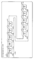
- FIG. 2A shows a specific example in which three secondary batteries 301 a, 301 b and 301 c are connected in series among a plurality of secondary batteries constituting the first battery 301.
- Each secondary battery is provided with a switch, and is connected to the bypass circuit by switching the switch.
- the switch uses a power MOSFET or the like.
- FIG. 2B shows a state in which the switch is switched to stop power supply to the secondary battery 301b.
- Each secondary battery 301a, 301b, 301c controls the monitor or the switch by the abnormality monitoring unit 300.
- the abnormality monitoring unit 300 inputs parameters of the secondary batteries 301a, 301b, and 301c to a neural network, and analyzes the state of the secondary battery.
- a set of current data and voltage data of the secondary battery can be sequentially sampled and read at fixed time intervals, stored in a predetermined number, and used as an input parameter.
- the input parameter for example, time
- a set of current data and voltage data of the secondary battery at each time can be used as the input parameter.
- the voltage of the secondary battery is, for example, a potential difference between both terminals of the secondary battery.
- the capacity of the secondary battery can be determined, for example, by the product of the current and time of the secondary battery.
- the capacity of the storage battery may be determined using a coulomb counter CC.
- SOC state of charge
- the SOC of the secondary battery is obtained by subtracting the absolute value of the discharge capacity from the absolute value of the charge capacity of the secondary battery, and is expressed as a ratio to the full charge capacity.
- the SOC of the secondary battery may be determined by estimation from the voltage of the secondary battery.
- the voltage In charging and discharging secondary batteries, the voltage generally changes depending on the magnitude of the current value. For example, the voltage drop due to the resistance of the secondary battery changes with the magnitude of the current value. Therefore, the resistance of the secondary battery may be able to be calculated from the relationship between the magnitude of the current value and the voltage. The resistance value calculated in this manner may be used as an input parameter.
- an open circuit voltage (OCV: sometimes referred to as open circuit voltage) of the secondary battery may be used.
- the open circuit voltage of the secondary battery is, for example, a potential difference between both terminals of the secondary battery in a state in which no current flows in the secondary battery.
- the state in which no current flows in the secondary battery means, for example, a state in which no load is applied to the secondary battery, and a state in which the charging circuit is not electrically connected to the secondary battery.
- the resistance of the secondary battery can be calculated by comparing the open circuit voltage with the voltage in a state where a significant current flows in the secondary battery.
- the abnormality monitoring unit 300 has a microcomputer and can detect micro shorts between the positive electrode and the negative electrode of the secondary battery by inputting the parameters of the secondary battery into a preprogrammed equation and performing calculation.
- a circuit that performs neural network operations may be incorporated into the abnormality monitoring unit 300.
- the connection between the other normal battery and the abnormal battery is disconnected by switching the switch.
- the switch By switching the switch, one battery can not be used, and the remaining batteries compensate for the output. Or amplified to a desired voltage by another circuit.
- the circuit (microcomputer) for performing neural network calculation may be mounted on a vehicle or may be mounted on a portable information terminal.
- the microcomputer has a CPU, a ROM, a RAM, and the like.
- the neural network operation may communicate with another computer and use data stored in the other computer. When communicating with another computer and performing neural network operation using data stored in another computer, it is possible to perform neural network operation using a huge amount of data.
- a circuit that performs neural network operations may be incorporated in the battery controller 302. By doing so, the number of IC chips can be reduced.
- the abnormality monitoring unit 300 By detecting a secondary battery in which an abnormality such as a micro short occurs or the like by the abnormality monitoring unit 300, safety can be secured by not using only the secondary battery by switching the switch. It is possible to avoid the danger of continuing to use the abnormal secondary battery and the adverse effects on other secondary batteries.
- the present embodiment shows an example of the configuration of the neural network NN.
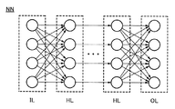
- FIG. 3 shows an example of a neural network of one embodiment of the present invention.
- the neural network NN shown in FIG. 3 has an input layer IL, an output layer OL, and a hidden layer (intermediate layer) HL.
- the neural network NN can be configured by a neural network having a plurality of hidden layers HL, that is, a deep neural network.
- the learning used for deep neural networks may be called deep learning.
- the output layer OL, the input layer IL, and the hidden layer HL each have a plurality of neuron circuits, and neuron circuits provided in different layers are connected via a synapse circuit.
- the neural network NN has a function of analyzing the state of the storage battery added by learning. Then, when the measured parameters of the storage battery are input to the neural network NN, arithmetic processing is performed in each layer. Arithmetic processing in each layer is performed by a product-sum operation of the output of the neuron circuit of the front layer and the weighting factor.
- the layer-to-layer connection may be a full connection in which all neuron circuits are connected to each other, or a partial connection in which some neuron circuits are connected to each other.
- a convolutional neural network may be used, in which only certain units are coupled between adjacent layers and have convolutional and pooling layers.
- the CNN is used, for example, for image processing.
- the convolutional layer for example, a product-sum operation of image data and a filter is performed.
- the pooling layer is preferably placed immediately after the convolutional layer.
- the convolution layer has a function of performing convolution on image data.
- the convolution is performed by repeating a product-sum operation of a part of the image data and the filter value of the weight filter. Convolution in the convolution layer extracts features of the image.
- a weight filter can be used for the convolution.
- the image data input to the convolutional layer is subjected to filter processing using a filter.
- the data subjected to convolution is converted by the activation function and then output to the pooling layer.
- the activation function ReLU (Rectified Linear Unit) or the like can be used.
- ReLU is a function that outputs “0” when the input value is negative, and outputs the input value as it is when the input value is “0” or more.
- a sigmoid function, a tanh function or the like can be used as the activation function.
- the pooling layer has a function of performing pooling on image data input from the convolutional layer. Pooling is a process of dividing image data into a plurality of areas, extracting predetermined data for each area, and arranging the extracted data in a matrix. Pooling reduces the image data while leaving the features extracted by the convolutional layer. As pooling, maximum pooling, average pooling, Lp pooling and the like can be used.
- CNN convolutional neural network
- the entire bonding layer be arranged.
- the entire bonding layer may be arranged in multiple layers.
- the entire combined layer preferably has a function of performing image determination using image data subjected to convolution and pooling.
- the configuration example of the neural network NN shown in FIG. 4A may be called a recurrent neural network (RNN).
- RNN recurrent neural network
- the hidden layer HL has a feedback path
- the output of the hidden layer HL is inputted (fed back) to itself.
- RNN it is possible to analyze time series data and predict data.
- data after a predetermined time may be able to be estimated based on a past charge / discharge curve.
- the weighting factor from the input layer IL to the hidden layer HL is denoted as win, the weighting factor from the hidden layer HL to the output layer OL as wout, and the weighting factor for feedback from the hidden layer HL as Wr.
- the RNN develops a time axis so that a different layer (input layer IL (1) is generated for each time (each time from time T (1) to T (x) in FIG. 4). ) To the input layer IL (x), the hidden layer HL (1) to the hidden layer HL (x), and the output layer OL (1) to the output layer OL (x)).
- the RNN By developing RNN in the time direction, it can be regarded as a forward propagation network without a feedback path as shown in FIG. 4 (C).
- LSTM long / short-term memory As the neural network, a configuration called Long Short-Term Memory (LSTM long / short-term memory) can be used.
- the LSTM stores the state by having the hidden layer in the RNN have memory cells, and can perform analysis, such as guessing, for a longer time.
- a configuration example of a neural network NN having a learning function will be described.
- a configuration example of the neural network NN is shown in FIG.
- the neural network NN is composed of a neuron circuit NC and a synapse circuit SC provided between the neuron circuits.
- FIG. 5A shows a configuration example of a neuron circuit NC and a synapse circuit SC which constitute the neural network NN.
- Input data x 1 to input data input data x L (L is a natural number) are input to the synapse circuit SC.
- the synapse circuit SC has a function of storing a weighting coefficient w k (k is an integer of 1 or more and L or less). Weight coefficient w k corresponds to the strength of coupling between neuron circuits NC.
- this value exceeds the threshold ⁇ of the neuron circuit NC, the neuron circuit NC outputs a high level signal y. This phenomenon is called firing of the neuron circuit NC.
- FIG. 5 A model of a neural network NN constituting a hierarchical perceptron by using a neuron circuit NC and a synapse circuit SC is shown in FIG. 5 (B).
- the neural network NN has an input layer IL, a hidden layer (intermediate layer) HL, and an output layer OL.
- Input data x 1 to input data x L are output from the input layer IL.
- the hidden layer HL has a hidden synapse circuit HS and a hidden neuron circuit HN.
- the output layer OL has an output synapse circuit OS and an output neuron circuit ON.
- the hidden neuron circuit HN, the input data x k, the value obtained by the product-sum operation using a weight coefficient w k held in the hidden synapse circuit HS is supplied.
- the output neuron circuit ON, the output of the hidden neuron circuit HN, the value obtained by the product-sum operation using a weight coefficient w k held in the output synapse circuit OS is supplied.
- the output neuron circuit ON, the output data y 1 to the output data y n is output.
- the neural network NN to which predetermined input data is given has a function of outputting, as output data, a value according to the weight coefficient held in the synapse circuit SC and the threshold ⁇ of the neuron circuit.
- the neural network NN can perform supervised learning by inputting teacher data.
- FIG. 5C shows a model of a neural network NN that performs supervised learning using an error back propagation method.
- FIG. 5B and 5C show one hidden layer HL
- the number of hidden layers HL can be two or more.
- Deep learning can be performed by using a neural network (deep neural network (DNN)) having two or more hidden layers HL. Thereby, the precision of state prediction of a storage battery can be raised.
- DNN deep neural network
- the RNN by time-expanding the RNN, it can be regarded as a forward propagation network without a feedback path.
- the weighting factor can be changed based on teacher data using the above-described error back propagation method or the like.
- a neural network is used for prediction and detection of occurrence of abnormality (specifically, occurrence of micro short) of a secondary battery.
- LSTM a recursive neural network
- the LSTM network is a model suitable for handling time-series data, and can measure the charging voltage at regular intervals and predict the charging characteristics slightly ahead of the accumulated time-series data.
- the network model of LSTM is shown in FIG. 6 (A).
- input layer indicates an input layer
- h1 and h2 indicate hidden layers
- output layer indicates a main layer.
- the solid line in FIG. 6B indicates the charging curve during charging, and the dotted line portion indicates the predicted charging curve.
- a normal charge curve is learned, and it is determined that there is no abnormality during a period in which the slightly predicted predicted charge curves overlap, as shown at the right end of the charge curve in FIG. 6C. It is detected by judging that there is an abnormality when waveform distortion, that is, micro short-circuit occurs and deviation occurs in the normal charge curve.
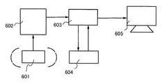
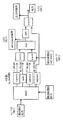
- FIG. 7 is a block diagram of an apparatus that simulates micro shorts generated in a lithium ion secondary battery, predicts its behavior, and shows the appearance (charging curve) on a display in real time.
- reference numeral 601 denotes a pseudo abnormality occurrence switch
- reference numeral 602 denotes an emulator which can be regarded as a battery.
- Charge measurement data is output from the emulator 602, and measurement and determination are performed by the controller IC 603.
- Input data for product-sum operation is input to the microcomputer 604 from the controller IC 603, the operation result is output from the microcomputer 604, the display color is changed, and the data of the inference result and the measurement data are superimposed on the display 605.
- the display 605 of the notebook personal computer can display two charge curves (for example, green: measurement data, yellow: predicted charge curve).
- FIG. 7 shows an example in which one microcomputer is used, a plurality of one hundred or more secondary batteries may be used in a short time with high accuracy.
- the input data for learning will be described with reference to FIGS. 8A and 8B.
- the voltage range of the secondary battery is from 3.0 V to about 4.2 V, and based on the time of the condition that takes the most time to charge, other curves pad the end without data with the maximum voltage to the last time Do.
- the sequence is cut out and set to the number of mini-batches. As shown in FIG. 8A, the start position of the sequence is randomly determined.
- the data of the number of mini-batches and the sequence length become input data of the neural network model. That is, as shown in FIG. 8B, the input data is a two-dimensional array of the number of mini-batches and the sequence length.
- the training data is a two-dimensional array of minibatch numbers and sequence lengths.
- inference data is a two-dimensional array in which the number of minibatches is fixed to one.
- FIG. 8B shows that mini-batch number data is stored in the array x 801 sequentially from the top of the sequence of input data, and data one array ahead of the array x 801 is stored in the array t 802.
- FIG. 8C shows the setting, where the sequence length (ALL SEQUENCE) of the whole graph is set to 300, and the front half 803 of the sequence length (LENGTH OF SEQUENCE) is used for prediction, and the predicted data length 804 And the difference between the measured value and the measured value.
- LSTM is a model suitable for time series data. This makes it possible to predict charging characteristics in real time and detect any abnormality immediately.
- the circuit configuration is complicated and high calculation accuracy is required.
- t is time and l is the index of the layer. That is, t-1 represents the previous time, and l-1 represents the previous layer.
- ⁇ in the above equation which means a Hadamard product (element product) represents element wise multiplication, and an operation such as the following equation is performed.
- T is a matrix operation for converting 2n dimensions to 4n dimensions, and “sigm” and “tanh” are calculated for each of n elements, and a vector having n elements, i (input gate), f ( Convert to forget gate), o (output gate), g (input modulation gate).
- Sigm means a smoid function
- tanh means a "hyperbolic tangent function”.
- the types of operations are product-sum operations, element wise multiplication, and activation functions (sigmoid or tanh). Note that LSTM sometimes interposes a network of all connections, and "product-sum operation" is also performed there.
- the cell state and the output save the previous value and use it in the next time step. Each time an input, new data is input. (Cell state, the stored value of the output is unnecessary after it is used as the input value, so it can be rewritten.)
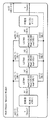
- FIG. 9 shows a conceptual diagram in which a measured value (Measured value) is input to a prediction unit (PU) and a predicted value (Predicted value) is output.
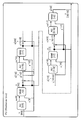
- the configuration of PU in FIG. 9 is shown in FIG.
- FIG. 11 shows a configuration of an AU (Approach Unit) in FIG.
- the unit of NNM (Neural Network Model) of FIG. 11 is shown in FIG.
- W, W lat , W up are weights
- b, b up are unit biases.
- FIG. 12 X (Scalar: quantity) is input, and a conceptual diagram in which Y (Scalar: quantity) is output after all bonds, LSTMs 1, 2, 3 and all bonds are output.
- cs is a cell state.
- the unit of LSTM in FIG. 12 is shown in FIG.
- FIG. 13 shows an algorithm of LSTM.
- m is element-wise multiplication (also referred to as a Hadamard product) and is a multiplication of variables, it is necessary to change the value each time.
- the network has five layers, of which LSTM is three layers (LSTM1, LSTM2, and LSTM3).
- the number of hidden layers was 30.
- the number of data used for inference is 20 points, and the data to be predicted is 20 points ahead.
- 2n ⁇ 4n 8n times 2 multiplications and 2n additions are performed.
- the above calculation also sums the values.) Therefore, n As becomes larger, the proportion of MAC processing in operation increases.
- the first algorithm uses only the input and the output of the previous time when obtaining i, f, o, and g. In this case, cell state is used to obtain i, f, and o.
- Chainer uses the first algorithm.
- the procedure of FIG. 13 (however, the procedure of only forward) will be described. As a first step, a matrix of “1 ⁇ 5” for input data h (0, t) (number of arrays is 1) at time t Multiply to obtain an array h (1, t) (array h (1) has five elements).
- the array h (1, t) and the output array h (2, t ⁇ 1) of the previous time are multiplied by the “10 ⁇ 20” matrix to obtain the array h (2, t) .
- array h (2) has 20 elements).
- the sequence a (2, t) is divided into four groups of five each, and the activation function is calculated for each. (The sequences “i”, “f”, “o”, “g” have 5 variables).
- Element-wise multiplication also referred to as a Hadamard product shown in Equation 3 and Equation 4 is performed to obtain cell state “c (2, t) ” and array h (2, t) .
- the cell state “c (2, t) ” and the array h (2, t) are passed to the next time operation, and initially there is no cell state “c” of the previous time (0 vector).
- h (2, t) (the number of arrays is 5) is multiplied by the “5 ⁇ 1” matrix to obtain an array h (3, t) to be output (the array shown in equation 5 below ) h (3, 1) has one element).
- the waveform predicted by the above algorithm can be predicted accurately, and if an abnormality can be detected, it is possible to construct a control system that immediately stops charging or displays a warning.
- Embodiment 4 In this embodiment, an example of an electronic device incorporating the charge control device for a plurality of secondary batteries described in Embodiment 1 will be described.
- a display device also referred to as a television or a television receiver
- a personal computer such as a desktop type or a notebook type, a computer Monitors, electronic organizers, electronic translators, toys, voice input devices such as microphones, electric shavers, electric toothbrushes, high frequency heating devices such as electric toothbrushes, microwave ovens, electric rice cookers, electric washing machines, electric vacuum cleaners, water heaters, Fans, hair dryers, air conditioning equipment such as humidifiers and dehumidifiers and air conditioners, dishwashers, tableware dryers, clothes dryers, futon dryers, electric refrigerators, electric freezers, electric refrigerators, DNA freezers , Flashlights, electric tools, smoke detectors, alarm devices such as gas alarm devices and security alarm devices, industrial robots, hearing aids, cardiac pacemakers Medical equipment such as X-ray imaging devices, radiation measuring instruments, electric massagers and dialysis devices, medical devices,
- the charge control device for a plurality of secondary batteries shown in the first embodiment has high safety, and therefore the safety of a vehicle incorporating the same is also enhanced.
- next-generation clean energy such as hybrid vehicles (HEVs), electric vehicles (EVs), or plug-in hybrid vehicles (PHEVs) You can realize a car.
- HEVs hybrid vehicles
- EVs electric vehicles
- PHEVs plug-in hybrid vehicles
- the storage device can also be mounted on a moving object such as a planetary probe or a spacecraft.
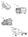
- FIG. 14 illustrates a mobile using one aspect of the present invention.
- An automobile 2001 shown in FIG. 14A is an electric automobile using an electric motor as a motive power source for traveling. Alternatively, it is a hybrid vehicle that can appropriately select and use an electric motor and an engine as power sources for traveling.
- a plurality of secondary batteries are installed at one or more locations.
- An automobile 2001 shown in FIG. 14A includes a battery pack 2100.
- the battery pack includes a secondary battery module to which a plurality of secondary batteries are connected, and a charge control device electrically connected to the secondary battery module. Have.
- a plurality of secondary batteries are monitored using the charge control device for a secondary battery shown in Embodiment 1, and one of the plurality of secondary batteries is charged and discharged while the vehicle is operating. If an abnormality occurs in the secondary battery, switch the switch and bypass the abnormal secondary battery to stop using the abnormal secondary battery.
- safety can be improved.
- the cruising distance can be extended, for example, by switching the switch of the large-deteriorated, low-voltage secondary battery to stop using it.
- power supply may be interrupted when the lowest voltage of the secondary battery or the average voltage of all the secondary batteries falls below the set value. If the charge control device of the present embodiment is used, the voltage of the lowest secondary battery can be changed by switching the switches of several secondary batteries, and the average voltage of all the secondary batteries can be increased.
- the automobile 2001 can charge the power storage device of the automobile 2001 with power supplied from an external charging facility by a plug-in method, a non-contact power feeding method, or the like.
- the charging method and the standard of the connector may be appropriately performed by a predetermined method such as CHAdeMO (registered trademark) or combo.
- the charging device may be a charging station provided in a commercial facility or may be a household power source.
- the power storage device mounted on the automobile 2001 can be charged by external power supply by the plug-in technology. Charging can be performed by converting alternating current power to direct current power via a conversion device such as an ACDC converter.
- the power receiving device may be mounted on a vehicle, and power may be supplied contactlessly from a ground power transmitting device for charging.
- charging can be performed not only while the vehicle is stopped but also while it is traveling by incorporating the power transmission device on the road or the outer wall.
- power may be transmitted and received between two vehicles using this non-contact power feeding method.
- a solar cell may be provided in the exterior of the vehicle to charge the power storage device when the vehicle is stopped or traveling.
- an electromagnetic induction method or a magnetic resonance method can be used for such non-contact power supply.
- the charging time can also be shortened.
- FIG. 14 (B) shows a large transport vehicle 2002 having a motor controlled by electricity as an example.
- the secondary battery module of the transport vehicle 2002 has, for example, four secondary batteries of 3.5 V or more and 4 V or less as four cell units, and has a maximum voltage of 170 V in which 48 cells are connected in series. Since the same function as that of FIG. 14A is provided except that the number of secondary batteries constituting the secondary battery module of the battery pack 2101 is different, the description is omitted.
- FIG. 14 (C) shows a large transport vehicle 2003 having a motor controlled by electricity as an example.
- the secondary battery module of the transport vehicle 2003 has, for example, a maximum voltage of 600 V in which one hundred or more secondary batteries of 3.5 V or more and 4 V or less are connected in series. Since the same function as that of FIG. 14A is provided except that the number of secondary batteries constituting the secondary battery module of the battery pack 2102 is different, the description is omitted.
- FIG. 14D shows an aircraft 2004 having an engine that burns fuel as an example.
- An aircraft 2004 illustrated in FIG. 14D includes a plurality of secondary batteries connected to form a secondary battery module, and includes a battery pack 2103 including the secondary battery module and a charge control device.
- the secondary battery module of the aircraft 2004 has, for example, a maximum voltage of 32 V in which eight 4 V secondary batteries are connected in series.
- the safety of the aircraft 2004 is enhanced by mounting a battery pack 2103 including a charge control circuit electrically connected to the secondary battery module.
- This embodiment can be implemented in appropriate combination with at least a part of the other embodiments described in this specification.
Landscapes
- Engineering & Computer Science (AREA)
- Power Engineering (AREA)
- Manufacturing & Machinery (AREA)
- Chemical & Material Sciences (AREA)
- Chemical Kinetics & Catalysis (AREA)
- Electrochemistry (AREA)
- General Chemical & Material Sciences (AREA)
- Sustainable Development (AREA)
- Life Sciences & Earth Sciences (AREA)
- Sustainable Energy (AREA)
- Transportation (AREA)
- Mechanical Engineering (AREA)
- Microelectronics & Electronic Packaging (AREA)
- Physics & Mathematics (AREA)
- General Physics & Mathematics (AREA)
- Secondary Cells (AREA)
- Charge And Discharge Circuits For Batteries Or The Like (AREA)
- Electric Propulsion And Braking For Vehicles (AREA)
- Tests Of Electric Status Of Batteries (AREA)
Abstract
L'invention concerne un système de stockage d'énergie très sécurisé. Lors de l'utilisation d'un nombre n (n est un nombre entier supérieur ou égal à 3) de batteries secondaires dans un véhicule tel qu'un véhicule électrique, la présente invention surveille l'état de chacune des batteries secondaires à l'aide d'un moyen de détection d'anomalie, et lorsqu'une anomalie telle qu'un court-circuit est détectée, utilise une configuration de circuit qui isole électriquement seulement la batterie secondaire présentant l'anomalie détectée du système de charge ou du système de décharge. La surveillance d'anomalie est effectuée de manière séquentielle pour le nombre n de batteries secondaires en utilisant un ou plusieurs micro-ordinateurs, des batteries secondaires présentant une anomalie ou des batteries secondaires qui, selon la détection, présenteront une anomalie sont sélectionnées, et une instruction est fournie par l'intermédiaire de chaque commutateur de manière à contourner ces batteries secondaires.
Priority Applications (4)
| Application Number | Priority Date | Filing Date | Title |
|---|---|---|---|
| JP2019559418A JP7104065B2 (ja) | 2017-12-11 | 2018-11-30 | 充電制御装置 |
| US16/767,637 US11563238B2 (en) | 2017-12-11 | 2018-11-30 | Charging-control device and electronic device with secondary battery |
| JP2022109565A JP2022141752A (ja) | 2017-12-11 | 2022-07-07 | 充電制御装置 |
| US18/089,199 US11984562B2 (en) | 2017-12-11 | 2022-12-27 | Charging-control device and electronic device with secondary battery |
Applications Claiming Priority (2)
| Application Number | Priority Date | Filing Date | Title |
|---|---|---|---|
| JP2017-236608 | 2017-12-11 | ||
| JP2017236608 | 2017-12-11 |
Related Child Applications (2)
| Application Number | Title | Priority Date | Filing Date |
|---|---|---|---|
| US16/767,637 A-371-Of-International US11563238B2 (en) | 2017-12-11 | 2018-11-30 | Charging-control device and electronic device with secondary battery |
| US18/089,199 Continuation US11984562B2 (en) | 2017-12-11 | 2022-12-27 | Charging-control device and electronic device with secondary battery |
Publications (1)
| Publication Number | Publication Date |
|---|---|
| WO2019116145A1 true WO2019116145A1 (fr) | 2019-06-20 |
Family
ID=66820043
Family Applications (1)
| Application Number | Title | Priority Date | Filing Date |
|---|---|---|---|
| PCT/IB2018/059485 Ceased WO2019116145A1 (fr) | 2017-12-11 | 2018-11-30 | Dispositif de commande de charge et dispositif électronique ayant une batterie secondaire |
Country Status (3)
| Country | Link |
|---|---|
| US (2) | US11563238B2 (fr) |
| JP (2) | JP7104065B2 (fr) |
| WO (1) | WO2019116145A1 (fr) |
Cited By (2)
| Publication number | Priority date | Publication date | Assignee | Title |
|---|---|---|---|---|
| WO2022130936A1 (fr) * | 2020-12-17 | 2022-06-23 | 株式会社クボタ | Engin de chantier électrique |
| JP2024501304A (ja) * | 2021-01-08 | 2024-01-11 | エルジー エナジー ソリューション リミテッド | 電池管理装置および方法 |
Families Citing this family (13)
| Publication number | Priority date | Publication date | Assignee | Title |
|---|---|---|---|---|
| JP6973213B2 (ja) * | 2018-03-16 | 2021-11-24 | トヨタ自動車株式会社 | 二次電池システム、及び二次電池制御方法 |
| JP7001036B2 (ja) * | 2018-10-09 | 2022-01-19 | 株式会社デンソー | 車両用描画装置 |
| WO2020174299A1 (fr) * | 2019-02-25 | 2020-09-03 | 株式会社半導体エネルギー研究所 | Circuit de protection pour batterie secondaire et système de détection d'anomalie pour batterie secondaire |
| JP7298496B2 (ja) | 2020-01-31 | 2023-06-27 | トヨタ自動車株式会社 | 車両 |
| CN112953385A (zh) * | 2021-03-04 | 2021-06-11 | 深圳黑晶光电技术有限公司 | 一种光伏系统控制器、光伏系统及控制方法 |
| US20220414780A1 (en) * | 2021-06-23 | 2022-12-29 | 3Dom Inc. | Secondary battery management device |
| US12179608B2 (en) | 2021-12-03 | 2024-12-31 | Sustainable Energy Technologies, Inc. | Monitoring and managing temperature of power packs |
| WO2023102265A1 (fr) * | 2021-12-03 | 2023-06-08 | Sustainable Energy Technologies, Inc. | Système et procédé de gestion d'énergie d'un bloc d'alimentation pour un véhicule électrique comprenant une charge photovoltaïque |
| WO2023107514A1 (fr) | 2021-12-06 | 2023-06-15 | Sustainable Energy Technologies, Inc. | Système et procédé d'analyse de changements de température dans un stockage de batterie de supercondensateur pour véhicule électrique |
| US12296721B2 (en) | 2021-12-10 | 2025-05-13 | Sustainable Energy Technologies, Inc. | Method and systems to trickle charge electric vehicle's supercapacitors using solar energy |
| JP2023136721A (ja) * | 2022-03-17 | 2023-09-29 | 株式会社東芝 | 充電制御方法、充電制御装置及び電池搭載機器 |
| CN115825768B (zh) * | 2022-10-25 | 2025-09-09 | 上海美克生能源科技有限公司 | 基于边缘计算的电池快速诊断方法、存储介质及电子设备 |
| EP4624953A1 (fr) * | 2024-03-25 | 2025-10-01 | Sonova AG | Détermination de paramètres d'une batterie rechargeable d'un dispositif portable |
Citations (2)
| Publication number | Priority date | Publication date | Assignee | Title |
|---|---|---|---|---|
| JP2000354333A (ja) * | 1999-06-08 | 2000-12-19 | Sony Corp | 電源装置及びバッテリーユニット |
| JP2013172552A (ja) * | 2012-02-21 | 2013-09-02 | Ntt Facilities Inc | 組電池制御システムおよび組電池制御方法 |
Family Cites Families (14)
| Publication number | Priority date | Publication date | Assignee | Title |
|---|---|---|---|---|
| JP3935099B2 (ja) * | 2003-04-15 | 2007-06-20 | 株式会社デンソー | 車両用蓄電装置の内部状態検出システム |
| US7554296B2 (en) | 2005-02-14 | 2009-06-30 | Denso Corporation | Method and apparatus for detecting charged state of secondary battery based on neural network calculation |
| TWI411796B (zh) * | 2009-12-22 | 2013-10-11 | Ind Tech Res Inst | 電池循環壽命估測裝置 |
| DE102013215572A1 (de) * | 2013-08-07 | 2015-02-12 | Robert Bosch Gmbh | Elektrische Energiespeichervorrichtung und Verfahren zum Hochfahren der Spannung an deren Anschlüssen |
| JP2015059933A (ja) * | 2013-09-20 | 2015-03-30 | 株式会社東芝 | 二次電池の異常診断装置及び異常診断方法 |
| JP2015166710A (ja) | 2014-03-04 | 2015-09-24 | ソニー株式会社 | 蓄電部材状態推定装置、電池パック、電動車両、蓄電装置および蓄電部材状態推定方法 |
| KR102205293B1 (ko) * | 2014-04-18 | 2021-01-20 | 삼성전자주식회사 | 배터리 수명의 추정에서 발생하는 오차를 보정하는 방법 및 장치 |
| US9431837B2 (en) * | 2014-04-30 | 2016-08-30 | Johnson Controls Technology Company | Integrated battery management system and method |
| CN104614632B (zh) * | 2015-01-19 | 2017-11-28 | 清华大学 | 一种电池微短路的识别方法 |
| US20160239592A1 (en) * | 2015-02-12 | 2016-08-18 | Nec Laboratories America, Inc. | Data-driven battery aging model using statistical analysis and artificial intelligence |
| AU2016285501B2 (en) | 2015-06-30 | 2019-03-14 | Murata Manufacturing Co., Ltd. | Power storage system, controller, and storage battery charging and discharging method |
| JP2019506837A (ja) * | 2015-12-11 | 2019-03-07 | ブルー・ソリューションズ・カナダ・インコーポレイテッド | バッテリ保護デバイス |
| CN107329088B (zh) * | 2016-04-29 | 2021-05-14 | 株式会社日立制作所 | 电池的健康状态诊断装置和方法 |
| US10183590B2 (en) * | 2016-09-23 | 2019-01-22 | Faraday&Future Inc. | Electric vehicle battery monitoring system |
-
2018
- 2018-11-30 WO PCT/IB2018/059485 patent/WO2019116145A1/fr not_active Ceased
- 2018-11-30 US US16/767,637 patent/US11563238B2/en active Active
- 2018-11-30 JP JP2019559418A patent/JP7104065B2/ja not_active Expired - Fee Related
-
2022
- 2022-07-07 JP JP2022109565A patent/JP2022141752A/ja not_active Withdrawn
- 2022-12-27 US US18/089,199 patent/US11984562B2/en active Active
Patent Citations (2)
| Publication number | Priority date | Publication date | Assignee | Title |
|---|---|---|---|---|
| JP2000354333A (ja) * | 1999-06-08 | 2000-12-19 | Sony Corp | 電源装置及びバッテリーユニット |
| JP2013172552A (ja) * | 2012-02-21 | 2013-09-02 | Ntt Facilities Inc | 組電池制御システムおよび組電池制御方法 |
Cited By (5)
| Publication number | Priority date | Publication date | Assignee | Title |
|---|---|---|---|---|
| WO2022130936A1 (fr) * | 2020-12-17 | 2022-06-23 | 株式会社クボタ | Engin de chantier électrique |
| JPWO2022130936A1 (fr) * | 2020-12-17 | 2022-06-23 | ||
| JP7581380B2 (ja) | 2020-12-17 | 2024-11-12 | 株式会社クボタ | 電動作業機 |
| EP4265851A4 (fr) * | 2020-12-17 | 2024-11-20 | Kubota Corporation | Engin de chantier électrique |
| JP2024501304A (ja) * | 2021-01-08 | 2024-01-11 | エルジー エナジー ソリューション リミテッド | 電池管理装置および方法 |
Also Published As
| Publication number | Publication date |
|---|---|
| US11563238B2 (en) | 2023-01-24 |
| JP2022141752A (ja) | 2022-09-29 |
| JPWO2019116145A1 (ja) | 2021-01-21 |
| JP7104065B2 (ja) | 2022-07-20 |
| US20210005939A1 (en) | 2021-01-07 |
| US20230132746A1 (en) | 2023-05-04 |
| US11984562B2 (en) | 2024-05-14 |
Similar Documents
| Publication | Publication Date | Title |
|---|---|---|
| JP7104065B2 (ja) | 充電制御装置 | |
| JP7393102B2 (ja) | 二次電池の異常検出装置 | |
| JP7648831B2 (ja) | 二次電池の異常検知装置及び二次電池 | |
| JP7337781B2 (ja) | 蓄電装置の充電状態推定システム | |
| JP7134981B2 (ja) | 二次電池の異常検知システム及び二次電池の異常検出方法 | |
| JP7446990B2 (ja) | 蓄電装置の充電状態推定方法及び蓄電装置の充電状態推定システム | |
| US11480621B2 (en) | Capacity estimation method and capacity estimation system for power storage device | |
| US11804622B2 (en) | Abnormality detection method of power storage device and management device of power storage device | |
| US10137792B2 (en) | Vehicle control based on lithium plating detection in electrified vehicle battery | |
| JP7350700B2 (ja) | 充放電制御方法、充放電制御装置及び制御システム | |
| CN113646948A (zh) | 二次电池的充电状态推测方法、二次电池的充电状态推测系统及二次电池的异常检测方法 |
Legal Events
| Date | Code | Title | Description |
|---|---|---|---|
| 121 | Ep: the epo has been informed by wipo that ep was designated in this application |
Ref document number: 18888880 Country of ref document: EP Kind code of ref document: A1 |
|
| WWE | Wipo information: entry into national phase |
Ref document number: 2019559418 Country of ref document: JP |
|
| NENP | Non-entry into the national phase |
Ref country code: DE |
|
| 122 | Ep: pct application non-entry in european phase |
Ref document number: 18888880 Country of ref document: EP Kind code of ref document: A1 |